P43
P43 - Operator's manual - Sintemar
P43 - Operator's manual - Sintemar
- No tags were found...

You also want an ePaper? Increase the reach of your titles
YUMPU automatically turns print PDFs into web optimized ePapers that Google loves.
<strong>P43</strong> ®SubmergedRotary Jet MixerOperator’s Manual
<strong>P43</strong> ®SubmergedRotary Jet MixerCONTENTSEquipment descriptionEquipment operationInstallation andmaintenanceTechnical informationSpecific data12345
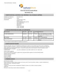
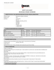
The following specifications apply to the <strong>P43</strong>®:1.3 Key parametersHEIGHT 548 mm (21.6 in)NOZZLE TIP TO TIP 738 mm (29.1 in)WEIGHT 205 kg (450 lb)* PRESSURE RATED 20 bar (295 psi)* TEMPERATURE RATING -10 to 93°C (14 to 200° F)GEARBOX OIL EP 320 (1 ¾ Imp. Gal.)(8 litres)(*) Higher pressures and temperatures available on request.1.4 Nozzle selectionThese range from 50mm (1.97") to 112.5mm (4.43"). Nozzle size selection is based on required jetrange, available pressure and flow rate for the <strong>P43</strong>® service.1.5 Impeller selectionThe speed of rotation can be varied by the flow rate through the <strong>P43</strong>® and also by a variety offactory fitted impellers. The speed range being 1.78 – 5.18 deg. min.1.6 Materials (see Figure 1.1)MAIN BODYNOZZLE BODYNOZZLE TIPIMPELLERIMPELLER SHAFTGEARCASEGEARCASE COMPONENTSFASTENINGS‘O’ RINGSMECHANICAL SEALAluminium BronzeNi Resist S.G. IronAluminium Bronze or Ni ResistAluminium Bronze or Ni Resist S.G. IronStainless SteelNi Resist S.G. IronPhosphor BronzeAluminium BronzeStainless SteelStainless SteelVitonHasteloy C. Stainless Steel1 Equipment Description2
Figure 1.1 – Schematic of <strong>P43</strong>®Veolia <strong>P43</strong>®. Made in UK. EPC, US and other patents granted and applied for.738 mmFLUID FLOW(INLET)8˝ ANSI FLANGEEARTH STRAPIMPELLER SHAFTST/STEEL 440MAIN BODYALUM. BRONZE AB2BEARING PLATENi RESIST D2WMECHANICAL SEALBELLOWS HASTELOY CST/STEELBAFFLE TO PREVENTDISCHARGE AGAINSTTANK SHELL(NOT INCLUDED INCENTRAL MOUNTED<strong>P43</strong>®)<strong>P43</strong>®MADE IN UKEPC, US AND OTHER PATENTSGRANTED AND APPLIED FORNOZZLESALUM. BRONZE AB2OR Ni RESIST D2BNOZZLE BODYNi RESIST D2WCAST IRON360mm548mmBASE PLATE GASKET344mm DIA360mm DIAFLANGED PLUG344mm DIA360mm DIAFLANGED PLUG1.11 Equipment Description3
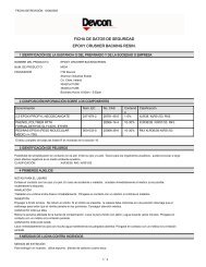
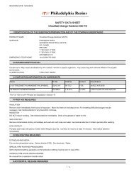
Equipment Operation2CONTENTS2.1 Operating Specifications.....................................................................................................12.2 Recommended Operating Interval..................................................................................12.3 Use of Shell Mounted <strong>P43</strong>® to de-sludge Tank........................................................ 62.4 Procedure for Processing Sludge Dispersed in Crude Oil......................................72.5 Routine Checks on Operation..........................................................................................72.6 Special Considerations........................................................................................................7Figures2.1 Flow Rate vs Cleaning Radius – Shell Mounted <strong>P43</strong>® andCentral Mounted <strong>P43</strong>® with one nozzle discharging various nozzlediameters – oil S.G 0.9.........................................................................................................22.2 Required Pressure Drop vs Cleaning Radius (Shell Mounted <strong>P43</strong>®)with various nozzle diameters – oil S.G 0.9................................................................32.3 Case Examples for <strong>P43</strong>® Specifications........................................................................42.4 Required Pressure Drop vs Cleaning Radius – <strong>P43</strong>® (Central Mounted).Two nozzles – various diameters – oil S.G. 0.9..........................................................5NOTE: In connection with Performance GraphsRequired pressure drop is defined as the pressure drop across the <strong>P43</strong>®, therefore,allowance must be made for any losses in pipelines and for the statichead of liquid in the tank.
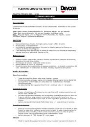
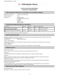
Equipment Operation22. Operation2.1 Operating specificationsDuring the normal operating sequence of the <strong>P43</strong>®, there will be external circumstances whichwill lead to a change in the normal flow rate and/or supply pressure. These changes will alter thecleaning radius of the <strong>P43</strong>® and could affect the overall effectiveness of the <strong>P43</strong>® installation.The graphs (Figures 2.1 to 2.4) enable the operator to calculate the impact of these changeson cleaning radius, and which remaining parameters would need to be altered to restore theinstallation to its normal operational effectiveness.EXAMPLE:In the case of a 260' (79m) diameter tank with three <strong>P43</strong>®(s) at equidistant positions around thecircumference of the tank, the following applies:For a 100mm nozzle from Figure 2.3 and Figure 2.4:CASE ‘A’Range Flow Pressure drop across <strong>P43</strong>®130' (39.5m) 3375 IGPM (921m 3 /hr) 83 psi (5.8kg/cm 2 )CASE ‘B’Should the flow be reduced to 3000 GPM (819m 3 /hr) Then from Figure 2.4:Range115′ (35m)CASE ‘C’Should the pressure be reduced by 5psi then (from Figure 2.3) the pressure drop across the <strong>P43</strong>® willreduce to (83-5) = 78 psi (5.48kg / cm 2 ).Range126′ (38.4m)2.2 Recommended operating intervalIt is strongly recommended that the <strong>P43</strong>® is run at least once per month to prevent sludge build-upand to ensure free movement of internal components. The frequency and duration of operationwill be a function of sludge deposition rates, but in general should be about 8 sweeps per nozzle ina month.2 Equipment Operation1
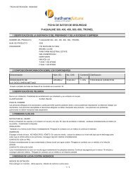
Figure 2.1 – Flow rate vs cleaning radiusShell mounted <strong>P43</strong>® or centre mounted <strong>P43</strong>® with one nozzle discharging various nozzle diameters. Oil S.G.0.9112.5mmm3/hr1092819FLOW RATE 1GPM40003000100.0mm87.5mmVARIOUS NOZZLE DIAMETERS75.0mm546200062.5mm50.0mm273 1000136 5005015601870218024902710030110 120CLEANING RADIUS33 361303914042150 160 170 FEET45 48 51 METRES2.12 Equipment Operation2
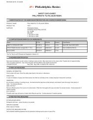
Figure 2.2 – Required pressure drop vs cleaning radius(Shell mounted <strong>P43</strong>®) with various nozzle diameters. Oil S.G. 0.91217062.5mm1216015050.0mm75.0mm87.5mm100.0mm101409130112.5mm1208110REQUIRED PRESSURE DROP765100908070VARIOUS NOZZLE DIAMETERS46050340230201105015601870218024902710030110 120 130CLEANING RADIUS33 36 3914042150 160 170 180 FEET45 48 51 54 METRES2.22 Equipment Operation3
Figure 2.3 – Case examples for <strong>P43</strong>® specificationsFigure 2.1 – Flow rate vscleaning radiusShell mounted <strong>P43</strong>® orcentre mounted <strong>P43</strong>® withone nozzle dischargingvarious nozzle diameters.Oil S.G. 0.9m3/hr1092819FLOW RATE 1GPM40003000112.5mm100.0mm87.5mmVARIOUS NOZZLE DIAMETERS75.0mm546200062.5mmCASE A50.0mm273 1000CASE B136 50050156018702180249027100 110 120CLEANING RADIUS30 33 361303914042150 160 170 FEET45 48 51 METRESFigure 2.2 – Required pressuredrop vs cleaning radius(shell mounted <strong>P43</strong>®) withvarious nozzle diameters.Oil S.G. 0.9121217016015050.0mm62.5mm75.0mm87.5mm100.0mm101409130112.5mm1208110REQUIRED PRESSURE DROP765100908070VARIOUS NOZZLE DIAMETERS43605040CASE A21302010CASE C5015601870218024902710030110 120 130CLEANING RADIUS33 36 3914042150 160 170 180 FEET45 48 51 54 METRES2.32 Equipment Operation4
Figure 2.4 – Required pressure drop vs cleaning radius<strong>P43</strong>® (central mounted) two nozzles – various diameters. Oil of S.G. 0.9kg/cm21211Ib/in217016050.0mm62.5mm75.0mm87.5mm100.0mm10150140112.5mm91308120110REQUIRED PRESSURE DROP765100908070VARIOUS NOZZLE DIAMETERS460503402302011050156018702180249027100 110 120CLEANING RADIUS30 33 361303914042150 160 170 FEET45 48 51 METRES2.42 Equipment Operation5
MONITORING <strong>P43</strong>® EFFECTIVENESSA tank monitoring procedure should be devised to• Determine the crude oil quality for selection of processing strategy• Measure the effectiveness of blending• Determine the rate and effectiveness of sludge re-suspension2.3 Use of shell mounted <strong>P43</strong>® to de-sludge tank(i)(ii)Take samples of sludge and measure:B S & W (Bottom Sediment and Water)Conduct sludge profile survey across the tankEstimate sludge quantityEmpty tank and fit <strong>P43</strong>® (see Section 3.3)(iii) Fill storage tank with crude oil to a minimum height such that the roof is floatingIt is advantageous to have a large volume of crude to disperse the sludgeA ratio of approximately 4:1 (crude to sludge) is usually sufficient(iv)(v)(vi)If a minimum level of crude has been used, raise roof legs to their operating position tominimise jet disturbance during cleaning operation. Alternatively fill the tank to a levelwhere the roof legs are above the centre line of the jetSample the crude oil after filling the tank and measure B S & W levelsGradually increase the pressure to each <strong>P43</strong>® until the designated rate is achieved(vii) For the tank cleaning operation, we recommend a minimum of eight sweeps per <strong>P43</strong>®. Thistime can be reduced if the customer is prepared to stop the operation, allow a 1-hour settlingtime and conduct sludge profile measurements. If the levels are satisfactory then the operationcan be stopped(viii) When the operation is stopped to assess sludge profiles, it is recommended that samples aretaken at the top, middle and bottom to determine B S & W levelsThis data will give you useful information on the operating characteristics of the <strong>P43</strong>® and willassist in assessing the processing needs of this mixture(ix) If sludge is still present in the tank and the B S & W level exceeds 15% in the bulk of thecrude oil, we recommend draining the tank and adding fresh crude oil for a further periodof <strong>P43</strong>® operationNOTE: SEQUENTIAL OPERATIONIf the refinery is limited for flow rate it is possible to operate the <strong>P43</strong>® on a sequential basis.However each <strong>P43</strong>® should be operated as outlined in section (vii). The total cleaning time would,therefore, be extended.Heating of the oil is also an advantage when de-sludging, with 60ºC the maximumrecommended temperature.2 Equipment Operation6
2.4 Procedure for processing sludge dispersed in crude oilThe sludge dispersed in the crude oil mixture may need to be blended in line with the feedstockfrom a neighbouring tank. The decision on the exact percentage of the blend should be based onthe composition of the sludge / crude oil mixtures. If the <strong>P43</strong>® has been used to de-sludge the tankwith a minimum crude level, then a blend of 5 to 10% could be required.The following parameters should be monitored to assess any downstream impacts:(i)B S & W and salt levels in the inlet and outlet of the desalterIn order to assess the fouling tendencies of the crude oil, monitor(i) Pressure drops across crude pre-heat exchangers before, during and after sludge /crude oil processing(ii)Overall heat transfer coefficients (‘U’ Values) across crude preheat exchangers,before, during and after sludge / crude oil processing2.5 Routine check on <strong>P43</strong>® operationIt is recommended that the following checks are conducted periodically:• Check sludge level in the crude oil tank• Check pressure readings at tank shell and ensure these correlate with the design pressurefor the installation• Monitor line filter pressure drop to ensure that the line filter is not blocked• During <strong>P43</strong>® operation, check indicator (where fitted) for correct <strong>P43</strong>® rotation2.6 Special considerationsIf the <strong>P43</strong>® is to be operated in an environment with oils which are solid at ambient temperatures,special precautions should be taken. These include:• Keeping the temperature of the <strong>P43</strong>® and vicinity elevated• Checking that the strainer(s) is clear• Checking the indicator (where fitted) to ensure the <strong>P43</strong>® is rotating• Checking the pressure and flow rate on starting against figures given for the installationsand/or previous results (see Figures 2.1 to 2.4)• Ensuring that the supply line to the <strong>P43</strong>® is drained / empty if the heat is to beswitched off2 Equipment Operation7
Installation andMaintenance3CONTENTSA. Installation...............................................................................................................................13.1 Equipment Supplied.............................................................................................................13.2 External Pipework Details...................................................................................................13.2.1 Details for Centre Mounted <strong>P43</strong>®....................................................................................13.2.2 Details for Shelf Mounted <strong>P43</strong>®......................................................................................23.3 Systems Installation / Commissioning......................................................................103.3.1 Centre Mounted <strong>P43</strong>®.......................................................................................................103.3.2 Shell Mounted <strong>P43</strong>® (for manways 30” or greater)..............................................103.3.3 Shell Mounted <strong>P43</strong>® (for manways less than 30” Ø).............................................113.3.4 <strong>P43</strong>® External Indicator....................................................................................................14B. Maintenance......................................................................................................................... 153.4 <strong>P43</strong>® Lubrication.................................................................................................................. 153.5 Recommended Operating Interval............................................................................... 153.6 External Indicator................................................................................................................ 153.7 Servicing Interval................................................................................................................. 15Figures3.1 Typical Modes for Operating <strong>P43</strong>®.................................................................................33.2 Alternative Installation Positions...................................................................................43.3 Pipework Details (Centre Mounted <strong>P43</strong>®)...................................................................53.4 Pipework Details (Shell Mounted <strong>P43</strong>®)..................................................................... 63.5 Details of Anchor Mounting (Centre Mounted <strong>P43</strong>®)............................................73.6 Typical Support Brackets....................................................................................................83.7 Suggested Alteration to Roof if Pontoon is likely to foul..................................... 93.8 Typical Installation of Indicator..................................................................................... 123.9 Indicator (Shell Mounted) <strong>P43</strong>® – E.5468.................................................................. 13
Installation andMaintenance3A. Installation3.1 Equipment suppliedVeolia provide only the <strong>P43</strong>®, which is filled with oil and ready to be mounted onto the appropriatesupporting pipework. The <strong>P43</strong>® is fitted with an 8 inch ANSI flat face mounting flange and iscomplete with fixing bolts, mating flange and an earthing strap.The <strong>P43</strong>® is supplied as a sealed unit. Breakage of this seal will invalidate warranty.Veolia do NOT provide any of the associated pipework, supports, valves, gauges etc. However we willgive technical advice on the installation and comment on any piping proposals.Schematics for typical pipework required for installation of the <strong>P43</strong>® are illustrated on thefollowing pages.Prior to installation of the <strong>P43</strong>® in any tank, full regard must be given to safety procedures to ensurethe protection of all personnel. All standard safety procedures as laid down by governmental bodies,safety organizations and the operating company must be complied with.3.2 External pipework details3.2.1 Details for centre mounted <strong>P43</strong>®A schematic of the pipework is illustrated on Figure 3.3. The following should also be consideredwhen designing the system:• .Pipe diameter to be selected to ensure that the desired pressure at the <strong>P43</strong>® can be achieved• Line Supports. See Figure 3.6• <strong>P43</strong>® mounting flanges are 8 inch ANSI B.16.5 and have been designed toAPI 650 standard• In-line strainer specification – see Figure 3.3Material – stainless steelScreen size – diamond-shaped preventing a particle sizegreater than 19mm (3/4") from passingIt is recommended that the strainer is of a ‘basket’ type design to facilitate cleaning.3 Installation and Maintenance1
NOTE: It is possible that sufficient strainers may have been fitted at the pumps, thus makingthe fitting of a further strainer unnecessary.• All new pipework must be flushed through before commissioning in order to clear anydebris that may have accumulated during installation. The use of temporary strainersduring commissioning is also recommended• Ensure centre line of jet does not directly impinge on internal piping, e.g. stream coils,water draw-off, etc• Ensure also that all specified alterations to internal pipework have been completed• Line vents for commissioning should be included• Pressure gauges are fitted to measure <strong>P43</strong>® inlet pressure and identify if line filteris blocking. These should be upstream and downstream of the line filter• Valve requirement. See Figure 3.4• <strong>P43</strong>® supports to withstand jet reaction quoted by Veolia• Fabrication of elbow assembly to facilitate <strong>P43</strong>® installation. See Figure 3.4• Minimum distance between vertical centre line of <strong>P43</strong>® and inside of tank wellshould be *500mm for the <strong>P43</strong>® with standard nozzle attachments• Recommended clearance under the <strong>P43</strong>® 125mm• Inlet flange designed to A.P.I 650 hence bolt holes straddle the centre line of the <strong>P43</strong>®• Correct <strong>P43</strong>® orientation is indicated by a groove included on the main stationary component.This groove marks the centre line of the <strong>P43</strong>® and should be directed at the centre of the tank• When steam coils are present, <strong>P43</strong>® must be positioned such that nozzle discharges belowsteam heating coils*This measurement should be increased to 800mm for <strong>P43</strong>®(s) with ‘S’ Bend Nozzle tube attachments(see Section 4 Page 13).3 Installation and Maintenance2
Figure 3.1 – Typical modes for operating <strong>P43</strong>®<strong>P43</strong>®SHELLVALVETO PUMPSEPARATE INLETOUTLET LINES<strong>P43</strong>®<strong>P43</strong>®<strong>P43</strong>®SHELLVALVEFROM PUMPHOT TAPFILTER<strong>P43</strong>® FEED LINE FROMADJACENT TANK<strong>P43</strong>®FILTERCOMMON INLET/OUTLET LINES<strong>P43</strong>®<strong>P43</strong>®<strong>P43</strong>®SHELLVALVERECIRCULATION<strong>P43</strong>®<strong>P43</strong>®KEYSHELL MOUNTED<strong>P43</strong>®<strong>P43</strong>®CENTRE MOUNTEDFILTERSHELLVALVEHOT TAPFILL AND DRAW3.13 Installation and Maintenance3
Figure 3.2 – Alternative installation positionsCLeaning radius = tank diameter x 0.712TWO MACHINE INSTALLATIONCLEANING RADIUS = TANK DIAMETER213THREE MACHINE INSTALLATION3.23 Installation and Maintenance4
Figure 3.3 – Typical pipework details (centre mounted <strong>P43</strong>®)PLAN VIEWREINFORCING PLATE MAY BEENLARGED TO COVER AREAS OFCORROSION IN TANK BOTTOM10" X 8" REDUCER(OR 12 X 8)PLAN VIEWOF TANK INSTALLATIONSEE EXPANSION BEND DETAIL.NOTE THAT PIPE SHOULD BE RUN TOAVOID INTERNAL STRUCTURE SUCHAS ROOF LEGS, DRAIN PIPE, ETCEXPANSION BEND DETAILSVENTS TO BE FITTED TOFACILITATE FILLING PIPESUPPORTSSEE DETAIL OF HOT TAP FILTER ANDFOLLOWING ARRANGEMENTPRESSURE GAUGE LOCATED UPSTREAMOF FILTER TO INDICATE WHEN THEFILTER BECOMES BLOCKEDINLINE FILTER TO BE STAINLESSSTEEL WITH A DIAMOND SHAPETO PREVENT PARTICLES GREATERTHAN 19mm FROM PASSINGCENTRE OF M/C MUST BE WITHIN1 METER OF CENTRE OF TANKGATE VALVETANKPRESSURE GAUGE12" X 10" REDUCERNON-RETURN VALVE2" 150 PSI VALVE12" X 12" X 10" REDUCING TEEGATE VALVE2" 150 PSI CHECK VALVEIF 12˝ PIPE IS USEDINSIDE TANK THEREDUCER NOT REQUIREDSIDE ELEVATIONTANK BOTTOM2" INSTANTANEOUSCOUPLINGDETAIL OF HOT-TAP-FILTER ANDFLUSHING ARRANGEMENTREINFORCING PADEXISTING FEED LINE(20 NB TYPE)SIDE ELEVATION3.33 Installation and Maintenance5
Figure 3.4 – Typical pipework details (shell mounted <strong>P43</strong>®)IN LINE FILTER TO BE STAINLESS STEEL WITHA DIAMOND SHAPE TO PREVENT PARTICLESGREATER THAN 19mm FROM PASSINGPLAN<strong>P43</strong>® INSTALLATIONPOSITION <strong>P43</strong>® WITH Ømm WIDEGROOVE FACING CENTRE OF TANKSUPPORTS2" 150 PSI VALVE16" X 16" X 10" OR 12" X12" X 10”REDUCING TEEDEPENDING ON LINE SIZEVENTS TO BE FITTED TOFACILITATE FILLING PIPE2" 150 PSI CHECK VALVEGATE VALVE12" DIA12" DIA16" DIASEE DETAIL OF HOT-TAP-FILTER ANDFLUSHING ARRANGEMENT(MAY REQUIRE 2ND FILTER)AFTER TAPPING INTO MAIN SUPPLY LINEIF THE FEED TO RING MAIN CAN GOEITHER WAY, THEN A 2ND FILTER MAYBE NECESSARY2" INSTANTANEOUSCOUPLINGREINFORCING PADEXISTING FEED LINE(24" – 30" N/BORE)SIDE ELEVATIONPLAN VIEW OF TANK INSTALLATION (SCALE 1 : 200)THE NUMBER OF WALL MOUNTED MACHINES MAY VARYFROM 1 TO 4. THIS EXAMPLE ILLUSTRATES 3 M/CsPRESSURE GAUGETANK WALLPRESSURE GAUGES LOCATED EITHERSIDE OF FILTER TO INDICATE WHEN THEFILTER BECOMES BLOCKEDDETAIL OF HOT-TAP-FILTER & FLUSHINGARRANGEMENT5/16" thk semi-circular shaped section with oneend blanked-off to be inserted into roof toprevent fouling when roof is in lowest positionNOTE: During a tank cleaning operation it isimportant to check that the roof will notfoul on the <strong>P43</strong>®. It may be necessary tooperate with the roof legs fully extendedNON-RETURN VALVESINCE ONE NOZZLE DISCHARGESAT A TIME GUSSETS TOWITHSTAND JET REACTION ASINDICATED IN QUOTATIONTANK SHELLROOFROOF PONTOON12" X 8" REDUCERGATE VALVEGUSSET ARRANGEMENTEXTERNAL INDICATOR(OPTIONAL EXTRA)Ø BO HOLE NEEDED INMANWAY COVERSee Fig 3.11 for typicalinstallation of indicatorTANK FLOORSIDE ELEVATIONOUTLINE OFOBSTRUCTIONMIN CLEARANCE CAN BE REDUCED IFREFINERY CONFIRMS THAT THE M/CWILL NOT FOUL ON TANK BOTTOMSIDE ELEVATION3.43 Installation and Maintenance6
Figure 3.5 – Details of anchor mounting (centre mounted <strong>P43</strong>®)ROOF<strong>P43</strong>®CHECK THAT WITH ROOF INLOWEST POSITION, THEREIS SUFFICIENT CLEARANCEBETWEEN <strong>P43</strong>® AND ROOF SUMPTO ENSURE THIS FLANGE ISMOUNTED HORIZONTALLY IT ISTO BE FITTED IN SITUATION ANDTESTED ON THE ELBOW TO ALLOWFOR SLOPE OF TANK BOTTOMWELD PLATE TOTANK BOTTOMGUSSET PLATES½" THICK30"CHECK JET WILLNOT IMPINGE ONWATER DRAW-OFF PIPE ORHEATING COILS. IFNECESSARY, THISDIMENSION MAYBE INCREASED30" X 30" X ½" PLATE36" X 36" X ½" PLATE3.53 Installation and Maintenance7
Figure 3.6 – Typical support brackets1" DIA. BAR6" x 3" CHANNEL6" x 3 ½" RSJCONCRETE BASETYPICAL SUPPORT BRACKETS OUTSIDE TANK5" x 2 ½" RSC ½" ‘U’ BOLT SUFFICIENTCLEARANCETO ALLOW FOREXPANSIONTANKBOTTOMTYPICAL SUPPORT BRACKET INSIDE TANK2 STIFFENING PLATES3.63 Installation and Maintenance8
Figure 3.7 – Suggested alteration to roof if pontoon is likely to foul pipeworkwith roof in lowest position (centre mounted <strong>P43</strong>®)5/16" THICK SEMI-CIRCULAR SHAPED SECTION WITHONE END BLANKED OFF TO BE INSERTED INTO ROOF TOPREVENT FOULING WHEN ROOF IS IN LOWEST POSITIONTANK SHELLROOFROOF POSITIONOUTLINE OF OBSTRUCTION3.73 Installation and Maintenance9
3.3 System installation commissioningThe following procedure is recommended when installing and commissioning the Veolia <strong>P43</strong>®.3.3.1 Centre mounted <strong>P43</strong>®a) Check that the correct nozzle size has been installed (i.e. in accordance with designspecification). Ensure that the impeller in the inlet to the <strong>P43</strong>® is free to rotate (by hand)b) Ensure by observing the centre line position of the nozzle that there will be no direct jetimpingement on internal piping e.g. stream coils, water draw-off etc. Also that all specifiedalterations to internal pipework have been completedc) To prevent impeller fouling on start-up, ensure that the lines feeding the <strong>P43</strong>®(s)(downstream from the line filter) have been flushed to remove scale deposits, welding rods etc.prior to installing the <strong>P43</strong>®(s). The use of a temporary strainer during commissioning is tobe recommendedd) Ensure that a pressure gauge 0-20 kg/cm² (0-300 psi) has been installed in the line betweentank shell and valve to measure <strong>P43</strong>® inlet pressuree) Fit gasket between the <strong>P43</strong>® and the saddle support and tighten bolts securely. Check the planeof the nozzle rotation to ensure that it is free from obstruction, and the centre line of the jetdoes not directly impinge on tank internalsf) The <strong>P43</strong>® is electrically continuous. To ensure electrical continuity with the pipework anearthing strap is supplied. This should be used to bond the inlet flange on the <strong>P43</strong>® to the pipeassembly. When assembled the whole surface of the strap and the fasteners should be coatedwith an oil resistant paintg) Ensure that the external indicator (where fitted) is in place and the flexible drive issecurely fastenedh) After line commissioning, gradually increase the pressure to the <strong>P43</strong>® until the designed rateis achievedi) Monitor the position of the <strong>P43</strong>® on the external indicator after half an hour operation andrecord the position after a further half an hour period to ensure that the <strong>P43</strong>® is rotating freely.Check the rotation rate of the <strong>P43</strong>® and ensure that it is within 10% of the specified time for therotation at the design pressure3.3.2 Shell mounted <strong>P43</strong>® (for manways 30” or greater)a) Check that the correct nozzle size has been installed (i.e. in accordance with designspecification). Ensure that the impeller in the inlet to the <strong>P43</strong>® is free to rotate (by hand)b) Ensure by observing the centre line position of the nozzle that there will be no direct jetimpingement on the internal piping e.g. steam coils, water draw-off etc. Also that all specifiedalterations to internal pipework have been completedc) To prevent impeller fouling on start-up, ensure that the lines feeding the <strong>P43</strong>®(s) (downstreamfrom the line filter) have been flushed to remove scale, deposits, welding rods, etc. prior toinstalling the <strong>P43</strong>®(s)d) Assemble <strong>P43</strong>® into inlet pipe fabrication together with gate valve and non-return valve,see Fig. 3.4e) NOTE: that the centre line of the <strong>P43</strong>® is marked by a machined slot. This slot must point tothe centre of the tankf) Check that the earthing strap is fixed across the flanges and is making a good contact and hasbeen painted3 Installation and Maintenance10
Figure 3.9 – Indicator (shell mounted) <strong>P43</strong>® E.54685 17 3315301840361131032 35MANWAY COVER3.93 Installation and Maintenance 13
3.3.4 <strong>P43</strong>® external indicatorSetting-up procedure for centre mounted unitRefer to drawings Nos, E.5468, E.5615 and schedule E.54681. Select position for indicator on tank wall. This will usually be on a manway flange or otherconvenient point. If a <strong>P43</strong>® wall mounted installation is being used, the indicator can bemounted on the same flange as the inlet pipeworkIf the installation is centrally mounted, the position of the indicator may be determined by otherfactors such as the route of the flexible drive (item 38).The flexible drive should be routed such that it runs past any available fixtures inside the tank suchas the <strong>P43</strong>® inlet pipework or the water draw-off line. This will enable the drive to be secured oncethe indicator has been set-up. The drive should not be run close to heating coils where these may beused after installation.Keep the number of changes in direction of the drive to a minimum. The indicator will operatesatisfactorily with up to six 90° bends.When routing the drive, ensure that no part of it can be trapped or caught by roof legs or roof waterdraw-off pipework when the roof is raised or lowered.2. Cut a hole 80mm dia. in the manway flange to coincide with the centre lines of the indicator3. Weld the studded flange (item 13) to the manway flange centrally around 80mm dia. hole4. Feed end of the flexible drive through the 80mm hole and bolt indicator to studded flange withitems (32) and (35), including gasket (item 10)5. Bolt manway flange to tank taking care not to damage the flexible drive6. Run drive along the desired route to the <strong>P43</strong>®7. Bolt <strong>P43</strong>® to inlet pipework flange. Choose two adjacent bolts on the <strong>P43</strong>® mounting flangefor the attachment of the mounting bracket (item 15). These will normally be in line with thedirection of the drive as it meets the <strong>P43</strong>®. Leave these two bolts undone and the others slack8. Slide mounting bracket over the bolts in the position shown on the drawing and secure.Tighten all <strong>P43</strong>® flange bolts fully9. Slide sprocket end of flexible drive onto the mounting bracket until the sprocket touches thepins on the bearing plate (item 1). Secure with items (5), (17) and (33), using Loctite 241 adhesiveor equivalent to coat the bolt threadsNote that Figure 3.9 shows a wall mounted installation. For a central mounted installation,the whole assembly at the <strong>P43</strong>® will be upside down10. Secure the whole length of the flexible drive to the fixtures along its route with stainless steelwire. ENSURE THAT THE DRIVE NEAR THE <strong>P43</strong>® IS CLEAR OF THE ROTATING NOZZLES11. When the <strong>P43</strong>® is run, there will be a delay of about 20 minutes before the indicator moves.When the <strong>P43</strong>® is moving, the indicating disc (item 16) will rotate at the same speed as the<strong>P43</strong>®. By timing the rotation of the disc through one revolution or any given angle, the speed ofthe <strong>P43</strong>® can be assessed3 Installation and Maintenance14
B. Maintenance3.4 <strong>P43</strong>® lubricationThe gearbox is lubricated by EP 320 oil. This should be renewed at the periodic services.3.5 Recommended operating levelThe frequency and duration of operation will depend on the rate of sludge deposition.But it is strongly recommended that the <strong>P43</strong>® be run for an approximate ONE ROTATIONOF THE NOZZLE at least ONCE A MONTH to ensure free movement of internal components.3.6 External indicatorAn external indicator can be supplied as an optional extra.INDICATOR(FOR SHELL MOUNTED <strong>P43</strong>®)INDICATOR(FOR CENTRE MOUNTED <strong>P43</strong>®)indicates nozzle movementand nozzle positionindicates nozzle movement onlyThe indicating mechanism is mechanically connected to the <strong>P43</strong>®. (See Figure 3.9).3.7 Servicing intervalFollowing 15 years of installation, it is recommended that the <strong>P43</strong>® is removed for routine service,together with the external indicator (where fitted). It should then be returned to Veolia or ourapproved service centre for complete overhaul. A substitute unit can be supplied at the time theexisting unit is removed to minimize tank outage time.3 Installation and Maintenance15
Technical Information4CONTENTS4.1 Service Enquiries....................................................................................................................14.2 Centre Mounted <strong>P43</strong>® Assembly(Parts Lists and Drawing)..........................................................................................2, 3, 44.3 Shell Mounted <strong>P43</strong>® Assembly(Parts List and Drawing)............................................................................................5, 6, 74.4 Customer Variables..............................................................................................................84.5 Impeller Shaft – Assembly .............................................................................................. 94.6 <strong>P43</strong>® Shell Mounted <strong>P43</strong>® – External Indicator(Parts List and Drawing)....................................................................................... 10, 11, 12
Technical Information44. Technical Information4.1 Service enquiriesAll service enquiries should be referred to Veolia at:Veolia Environmental ServicesDock Road SouthBromboroughWirralCH62 4SQTelephone: +44 (0) 151 6444300Fax: +44 (0) 151 6444301e-mail: VESUKp43@veolia.co.ukor via your Local Representative.4 Technical Information1
4.2<strong>P43</strong>® central mounted – G.A. E.5434ITEM TITLE QTY. PART No.1 MAIN BODY ASSY. – Central Mounted 5434012 NOZZLE BODY ASSEMBLY 1 5409023 BASE PLATE ASSEMBLY 1 5409034 GEARBOX ASSEMBLY 1 5409045 ―6 BEARING PLATE 1 5409067 IMPELLER 18 IMPELLER NUT 1 5409089 NOZZLE to suit10 ―11 MOUNTING FLANGE GASKET 1 54091112 BASE PLATE GASKET 1 54091213 KEY 1 54091314 FLANGED PLUG (⅜˝ BSP) 2 51918415 COPPER WASHER 2 54091516 ‘O’ RING 2 54091617 PTFE FRICTION DISC 1 54091718 ‘O’ RING 1 54091819 ‘O’ RING to suit 54091920 PTFE FRICTION DISC 1 540917A16A ‘O’ RING 1 540916A4 Technical Information2
4.2<strong>P43</strong>® central mounted – G.A. E.5434ITEM TITLE QTY. PART No.21 BOLT 54092122 BOLT 12 S.311223 BOLT to suit 54092324 SCREW 8 54092425 SCREW 5 54092526 WASHER – SPRING 8 54092627 WASHER – SPRING 12 54092728 WASHER – SPRING 8 54092829 WASHER – SPRING to suit 54092930 NUT 8 54093031 MECHANICAL SEAL 1 54093132 OIL 54093233 LOCTITE to suit 54093334 NOZZLE BLANK to suit 54093435 COPPER WASHER 1 54094036 FLANGED PLUG (½ “ BSP) 1 54093937 ─38 ─39 ─40 ─4 Technical Information3
Figure 4.2 – E 5434 <strong>P43</strong>® shore storage – tank cleaning (central mounted type)344mm738mmZZSECTION Y-Y(WITH NOZZLES REMOVED)3592329 19SECTION X-X37Ø 343mm FLANGE83872111127133161720263016A22548mm360mm3635VEOLIA <strong>P43</strong>®MADE IN UKEPC, US AND OTHER PATENTSGRANTED AND APPLIED FORXNOZZLE BLANKONE PER M/C MAY BEFITTED IN PLACE OFNOZZLE – ITEM 9 –IF REQUIREDYY161825X12Ø 360mm2824 15 14 4 3 24.24 Technical Information4
4.3<strong>P43</strong>® shell mounted – G.A. E.5409ITEM TITLE QTY. PART No.1 MAIN BODY ASSEMBLY (Shell mounted) 5409012 NOZZLE BODY ASSEMBLY 1 5409023 BASEPLATE ASSEMBLY 1 5409034 GEARBOX ASSEMBLY 1 5409045 ― ― ―6 BEARING PLATE 1 5409067 IMPELLER 18 IMPELLER NUT 1 5409089 NOZZLE 210 ― ― ―11 MOUNTING FLANGE GASKET 1 54091112 BASEPLATE GASKET 1 54091213 KEY 1 54091314 FLANGED PLUG (⅜˝ BSP) 2 51918415 COPPER WASHER 2 54091516 ‘O’ RING 2 54091617 PTFE FRICTION DISC 1 54091718 ‘O’ RING 1 54091819 ‘O’ RING 2 54091920 PTFE FRICTION DISC ―16A ‘O’ RING 1 540916A4 Technical Information5
4.3<strong>P43</strong>® shell mounted – G.A. E.5409ITEM TITLE QTY. PART No.21 BOLT 54092122 BOLT 12 S.311223 BOLT 4 54092324 SCREW 8 54092425 SCREW 5 54092526 WASHER – SPRING 8 54092627 WASHER – SPRING 12 54092728 WASHER – SPRING 8 54092829 WASHER – SPRING 4 54092930 NUT 8 54093031 MECHANICAL SEAL 1 54093132 OIL 54093233 LOCTITE to suit 54093334 ― ― ―35 COPPER WASHER 1 54094036 FLANGED PLUG (½" BSP) 1 54093937 ― ― ―38 ― ― ―39 ― ― ―40 ― ― ―4 Technical Information6
Figure 4.3 – E 5409 <strong>P43</strong>® shore storage – tank cleaning (wall mounted type)344mm738mmZZSECTION Y-Y(WITH NOZZLES REMOVED)3592329 19SECTION X-X37Ø 343mm FLANGE83872111127133161720263016A22548mm36XX360mm35VEOLIA <strong>P43</strong>®MADE IN UKEPC, US AND OTHER PATENTSGRANTED AND APPLIED FORYY16182512Ø 360mm2824 15 14 4 3 24.34 Technical Information7
4.4<strong>P43</strong>® customer variables E.5437ITEM TITLE QTY. PART No.1 NOZZLE – 2" as req. 5437012 NOZZLE – 2.5” as req. 5437023 NOZZLE – 3.0” as req. 5437034 NOZZLE – 3.5” as req. 5437045 NOZZLE – 4.0” as req. 5437056 NOZZLE – 4.5” as req. 5437007 ― ― ―8 ― ― ―9 ― ― ―10 ― ― ―1112 IMPELLER – 30° 1 54371213 ―1415 IMPELLER – 45° 1 54371516 IMPELLER – 50° 1 54371617 ―18 IMPELLER – 65° 1 54371819 ― ― ―20 ― ― ―4 Technical Information8
4.5<strong>P43</strong>® impeller shaft assembly E.5419ITEM TITLE QTY. PART No.1 IMPELLER SHAFT 1 5419012 BALL BEARING 1 5419023 CIRCLIP 1 5419034 Technical Information9
4.6<strong>P43</strong>® shell mounted – external indicator E.5468ITEM TITLE QTY. PART No.1 BEA RING PLATE ASSEMBLY 1 5492002 INDICATOR BODY 1 5496003 ― ― ―45 BOLT – HEX. HEAD 2 5468056 GEARBOX MOUNTING SUB- ASSEMBLY 1 5620007 SEAL HOUSING 1 5468078 DRIVE SHAFT 1 5468089 DRIVE PIECE ASSEMBLY 1 54990010 GASKET 1 54681011 BACKING WASHER (SEAL) 1 54681112 SPACING SLEEVE 1 54681213 STUDDED FLANGE 1 56160014 SLEEVE 1 54681415 MOUNTING BRACKET 1 54681516 INDICATOR DISC SUB-ASSEMBLY 1 56210017 NUT – HEX 2 54681718 PLATEWHEEL DISC SUB-ASSEMBLY 1 54681819 GEARBOX 1 54681920 BUSH 1 5468204 Technical Information10
4.6<strong>P43</strong>® shell mounted – external indicator E.5468ITEM TITLE QTY. PART No.21 THRUST WASHER 2 54682122 OIL SEAL 1 54682223 ‘O’ RING 1 54682324 ‘O’ RING 1 54682425 SPRING 1 54682526 SOCKET CAP-HEADED SCREWS 4 54682627 SOCKET CAP-HEADED SCREWS 2 54682728 BOLTS – HEX. HEAD 8 54682829 SOCKET CSK HD. SCREWS 6 54682930 SOCKET SET SCREW 1 54683031 NUT – HEX 1 2500/5432 NUT – HEX 16 54683233 WASHER 6 4007/7334 WASHER 1 4007/5935 WASHER 16 54683536 SOCKET CAP-HD. SCREWS 3 54683637 MOUNTING ADAPTOR 1 54683738 FLEXIBLE SHAFT ASSEMBLY 1 54910039 SIGHT GLASS 1 54683940 PLATE WHEEL 1 5468404 Technical Information11
Figure 4.6 – E 5468 external indicator <strong>P43</strong>®820 7 21 6 24 29 3933263823122592 22 11 313419 27 37 14ITEM 16 TO BE MOUNTED CENTRALLYON ITEM 37 WITH ARALDITEITEM 37 TO BE FITTED TO OUTPUTSHAFT OF ITEM 19 WITH LOCTITE 2704.64 Technical Information12
Fig 4.7 – ‘S’ bend nozzle adaptor1122A54311DOWEL TO BE A PRESS-FITWITH SIDE PLATES7104.74 Technical Information13
Specific Data5This section is for you to keep yourown relevant technical data