FLK Gas Sampling System - MPIP - Free
FLK Gas Sampling System - MPIP - Free
FLK Gas Sampling System - MPIP - Free
- No tags were found...

Create successful ePaper yourself
Turn your PDF publications into a flip-book with our unique Google optimized e-Paper software.
<strong>FLK</strong> <strong>Gas</strong> <strong>Sampling</strong> <strong>System</strong><br />
Operating Manual<br />
Preliminary Design Order No. ---------------------------------------<br />
Overview<br />
SQ254<br />
SQ255<br />
SQ251<br />
SQ252<br />
SQ253<br />
SQ256<br />
Legend:<br />
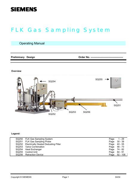
SQ250 <strong>FLK</strong> <strong>Gas</strong> <strong>Sampling</strong> <strong>System</strong> Page 1 - 29<br />
SQ251 <strong>FLK</strong> <strong>Gas</strong> <strong>Sampling</strong> Probe Page 30 - 39<br />
SQ252 Electrically Heated Dedusting Filter Page 40 - 55<br />
SQ253 Valve Combination Page 56 - 73<br />
SQ254 Heat Exchanger Page 74 - 82<br />
SQ255 Control Unit Page 84 - 91<br />
SQ256 Retraction Device Page 92 - 106<br />
Copyright ® SIEMENS Page 1 04/04
SQ250 <strong>FLK</strong> <strong>Gas</strong> <strong>Sampling</strong> <strong>System</strong><br />
We would like to point out that the content of this operating manual is not part of an earlier or existing agreement, consent, or<br />
a legal relationship nor should it be modified. All obligations on the part of SIEMENS can be taken from the relevant<br />
purchasing agreement which also contains the complete and solely valid warranty. These warranty provisions are neither<br />
extended nor restricted by this operating manual.<br />
We would also like to point out that for reasons of clarity not every conceivable problem situation in conjunction with the<br />
application of this product could be described in this operating manual. If you require further information or if particular<br />
problems occur which have not been dealt with in enough detail in the operating manual, you can request the required<br />
information via the local SIEMENS subsidiary.<br />
In the operating manual and in the warning information on the product, signal terms having the following meaning have been<br />
used:<br />
Danger as used in this operating manual and in warning information on the product itself means that death, severe injury and<br />
/ or substantial material damage will occur if the appropriate precautions are not taken.<br />
Warning as used in this operating manual and in warning information on the product itself means that death, severe injury<br />
and / or substantial material damage can occur if the appropriate precautions are not taken.<br />
Caution as used in this operating manual and in warning information on the product itself means that slight injury and / or<br />
material damage can occur if the appropriate precautions are not taken.<br />
Note as used in this operating manual denotes an important item of information about the product or a relevant part of the<br />
operating manual requiring particular attention.<br />
Copyright ® SIEMENS Page 3 04/04
SQ250 <strong>FLK</strong> <strong>Gas</strong> <strong>Sampling</strong> <strong>System</strong><br />
1. Introduction<br />
1.1 General information<br />
Warning! This system is operated by electricity. When operating electrical equipment, it is unavoidable that<br />
certain parts of this system carry a dangerous voltage.<br />
If the warning information is not followed, serious<br />
bodily injury and/or material damage may<br />
occur.<br />
Only appropriately qualified personnel should work on this equipment or in its vicinity. These<br />
persons must be thoroughly acquainted with all the warnings and maintenance precautions in<br />
accordance with this manual.<br />
The proper and safe operation of this device requires correct transport, storage, mounting and<br />
erection as well as proper operation and maintenance.<br />
In particular the general construction and safety regulations about working on power installations (e.g.<br />
DIN, VDE) should be followed as well as the regulations relating to the proper use of lifting<br />
equipment and tools and the use of personal protective gear (protective goggles, etc.).<br />
1.2 Personnel qualification requirements<br />
As understood in this operating manual and on warning notices qualified personnel are persons who are acquainted with the<br />
mounting, erection, maintenance and operation of this product and who possess appropriate qualifications for their<br />
occupation, such as for example covering:<br />
- training or instruction, and authorization for installing, removing, earthing and labeling power circuits, equipment and<br />
systems according to the currently valid standards of safety engineering,<br />
- training or instruction according to the currently valid standards of safety engineering in the care and use of<br />
adequate safety equipment;<br />
- training in first aid.<br />
This product left our factory in a perfectly safe condition. In order to maintain this condition and ensure the safe operation of<br />
the device, the information and warning notes given in this manual must be observed.<br />
Copyright ® SIEMENS Page 4 04/04
SQ250 <strong>FLK</strong> <strong>Gas</strong> <strong>Sampling</strong> <strong>System</strong><br />
1.3 Field of application<br />
For reasons of quality assurance, energy saving and environmental protection, continual flue gas analysis is needed in cement<br />
plants or rotary kiln facilities.<br />
The advantages of gas analysis in the kiln inlet and in precalcining are:<br />
• It enables conclusive assessment of the combustion processes and is therefore necessary for the optimization of burner<br />
control, fuel consumption and product quality.<br />
• Operating faults can be detected at an early stage and prevented with suitable countermeasures. Also, stabilized kiln<br />
management reduces noxious emissions and is an aid in environmental protection.<br />
However, up till now technical problems have been set against the advantages of continuous gas sampling. Above all, the<br />
high gas temperature of up to 1300° C, high dust concentration up to 2000 g/m 3 together with the high alkali, sulphate and<br />
chloride content in the gas inlets present problems. In addition any gas sampling system is subject to high mechanical stresses.<br />
Many of the numerous problems of continuous gas sampling can be avoided with the <strong>FLK</strong> gas sampling system matched to<br />
the requirements of cement production. During the development of the sampling system, emphasis was placed on the<br />
compatibility of the sampling equipment to the standards of process instrumentation. But measures for reducing investment,<br />
operational and maintenance costs were also considered. This means that the compact design that has been realized enables<br />
any maintenance, servicing and repair work which is needed to be simplified to such an extent that it can be carried out<br />
without highly qualified personnel.<br />
In order to increase the availability and reliability of the gas sampling system special emphasis was placed on automatic<br />
cleaning of the system matched to the kiln conditions. A crucial development objective was an increase in the operational<br />
safety, e.g. by protecting the electrostatic filters against explosion during CO formation.<br />
1.4 Construction<br />
The gas sampling system is basically formed from the following components:<br />
1. Liquid-cooled sampling probe<br />
2. Electrically heated dedusting filter<br />
3. Compressed air/valve combination<br />
4. Retraction device with electrical drive and additional pneumatic motor for redundancy<br />
5. Heat exchanger unit (cooling system)<br />
6. Programmable logic controller and monitoring unit.<br />
Components 1 to 4 are assembled on site to form a compact unit.<br />
Items 5 and 6 are set up separately.<br />
For the above components there are special, separate operating manuals in which more precise details about construction,<br />
erection, operation and servicing are given. This particularly includes the installation location for the probe (retraction device)<br />
and the electrical installation.<br />
Therefore, this operating manual only deals with the combined operation of the separate components, the laying of lines and<br />
the location of the moving parts of the equipment.<br />
The complete set of erection material according to the equipment parts list is included as supplied together with the items<br />
listed above. When the retraction device is supplied, the local control box for moving the probe and, if applicable, the<br />
emergency-stop button with mechanical interlocking are included.<br />
Copyright ® SIEMENS Page 5 04/04
SQ250 <strong>FLK</strong> <strong>Gas</strong> <strong>Sampling</strong> <strong>System</strong><br />
1.5 Mode of operation<br />
It is the rigid multi-pipe construction of the gas sampling probe that mainly guarantees a low level of service and<br />
maintenance. The cooling pipe, coolant return pipes and gas sampling probe can be quickly replaced using flange joints that<br />
are simple to release. The spatial separation of the gas sampling probe and the dedusting filter also have advantages for<br />
service and repair work.<br />
The somewhat unfavorable conditions during flue gas analysis in cement production demand special measures in the<br />
maintenance, repair and monitoring of all parts of gas analysis equipment. With this gas sampling system it was assumed that<br />
higher availability and reliability necessarily imply preventive, automatic maintenance. If dust build-up and baked-on deposits<br />
cannot be avoided, they must be detected on time by comprehensive monitoring devices and then effectively remedied.<br />
Baked-on deposits on the gas sampling probe are largely prevented by the high operating temperatures of up to 220° C.<br />
Special coolant ensures these high temperatures. In order that no temperature differences can arise between the probe and the<br />
filter, the filter is electrically heated; baked-on products in the filter space and silting up of the filter pores are therefore<br />
prevented.<br />
The motor-driven retraction device is another method of increasing the reliability and availability of the gas sampling system.<br />
It ensures quick and easy erection and removal of the gas sampling probe in the kiln inlet and protects it from any overheating<br />
if the cooling system fails.<br />
The numerous automatic functions are provided by a versatile, high performance programmable logic controller.<br />
A specially developed program satisfies these requirements.<br />
• During insertion and retraction the gas sampling probe can be cleaned internally and externally by compressed air via the<br />
built-in pipe.<br />
• It activates, either manually or automatically when required, the cleaning of the dedusting filter and the gas extraction<br />
pipe using compressed air.<br />
• It monitors the most important processes in the gas sampling, provides corresponding messages and initiates suitable<br />
countermeasures in the event of a fault.<br />
The user defines the type and scope of the countermeasures with exact parameters. This means, for example, that he can<br />
parameterize when and how often a cleaning program is to be started, how long the cleaning is to last or under which<br />
conditions the gas sampling probe is to be withdrawn from the kiln. The programmable logic controller and monitoring unit<br />
therefore provides an effective method of damage prevention.<br />
Copyright ® SIEMENS Page 6 04/04
SQ250 <strong>FLK</strong> <strong>Gas</strong> <strong>Sampling</strong> <strong>System</strong><br />
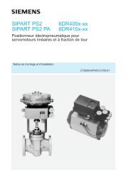
The different design versions of the system also contribute to optimized operation. Figure 2 shows the circuits for the analysis<br />
gas and for the compressed air for cleaning the gas sampling pipe and the dedusting filter. Figure 3 shows the coolant circuit<br />
for cooling the gas sampling probe.<br />
Fig. 2 <strong>Gas</strong> circuit for sampling device<br />
Legends:<br />
1 <strong>Gas</strong> sampling probe<br />
2 <strong>Gas</strong> sampling opening<br />
3 Coolant connection<br />
4 Retraction device<br />
5 Dedusting filter<br />
6 Valve combination<br />
7 Control cabinet for controller<br />
8 Installation pipe<br />
9 Valve for blowing dust return<br />
10 Local control box<br />
11 Flash light for process warning<br />
12 Horn for process warning<br />
13 Emergency-stop button<br />
14 Control Center<br />
71 Compressed air for purging 76 Condensate preseparator<br />
probe<br />
77 Low-pressure switch<br />
72 Compressed air for purging 78 Filter and Water separator<br />
filter<br />
79 Compressed air control valve<br />
73 Compressed air inlet<br />
80 Condensate output<br />
74 Dust-free measurement gas 81 Measuring gas line to analyzer cabinet<br />
75 Four-way motorized valve 82 Dust-laden measuring gas<br />
83 Control cable<br />
84 Control cable for pump controller and<br />
fault signals to analyzer cabinet<br />
85 Control cable for retraction device<br />
86 Filter supply cable<br />
The process gas to be analyzed is extracted by the gas sampling probe, cleaned in the electrically heated dedusting filter and<br />
passed to the gas analyzer device. Only a part of the gas flow with a particularly low dust content is extracted due to the<br />
specially formed sampling opening at the tip of the probe.<br />
Copyright ® SIEMENS Page 7 04/04
SQ250 <strong>FLK</strong> <strong>Gas</strong> <strong>Sampling</strong> <strong>System</strong><br />
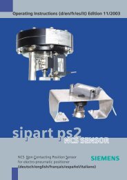
Fig. 3 Coolant circuit for sampling probe<br />
Legends:<br />
1 <strong>Gas</strong> sampling probe<br />
2 <strong>Gas</strong> sampling opening<br />
3 Coolant connection<br />
4 Retraction device<br />
7 Heat exchanger<br />
8 Installation pipe<br />
60 Coolant circulation pump<br />
61 Level monitoring<br />
62 Cooler with fan<br />
63 Expansion vessel<br />
64 Thermal switch<br />
65 Three-way control valve<br />
66 Flow monitor<br />
67 Temperature sensor<br />
68 Shut-off valve<br />
69 Coolant filter<br />
70 Coolant line<br />
71 Dust blow-back<br />
72 Corrugated hose<br />
82 Dust-laden measuring gas<br />
83 Control cable to control cabinet<br />
85 Control cable for retraction device<br />
The concept of the unpressurised, enclosed coolant circuit was selected for the cooling of the special synthetic heat transfer<br />
fluid. The liquid-air cooler with an expansion vessel, which handles the cooling of the heat transfer fluid, is the centre-piece<br />
of the heat exchanger unit. The axial fan provides the required air flow and the maintenance-free, high-temperature resistant<br />
centrifugal pump circulates the heat transfer fluid.<br />
Copyright ® SIEMENS Page 8 04/04
SQ250 <strong>FLK</strong> <strong>Gas</strong> <strong>Sampling</strong> <strong>System</strong><br />
1.6 Technical data<br />
Please refer to the separate operating manuals for technical data on the separate components.<br />
Electrical supply data:<br />
3/400V,3/230V,3/500V, + 10%,-15% ; 50...60 Hz<br />
Power rating 5.5 kVA<br />
230V, 115V + 10%,-15% ; 50...60 Hz<br />
Power rating 1.5 kVA<br />
Compressed-air supply data:<br />
6...8 bar<br />
Compressed air free of oil, dust and water<br />
Approx. 4...6 m 3 / h<br />
Measuring gas connection:<br />
Hose ID 6 mm<br />
Needs min. pump power of approx. 0.3 bar negative pressure<br />
Approx. 4 ... 7 l/min.-<br />
Heat output of heat exchanger unit:<br />
Approx. 69 kW heat output<br />
Temperature range up to 250° C<br />
Copyright ® SIEMENS Page 9 04/04
SQ250 <strong>FLK</strong> <strong>Gas</strong> <strong>Sampling</strong> <strong>System</strong><br />
2. Installation<br />
2.1 General information<br />
In cement production two main installation areas are relevant:<br />
• Kiln inlet<br />
• Precalcination<br />
It is essential that the installation location and the mounting are defined, with respect to the space requirement, between the<br />
machine supplier or user and SIEMENS<br />
Note: In relation to the individual components there are separate operating manuals in which the precise details<br />
of construction, installation, operation and servicing are dealt with comprehensively.<br />
This is especially relevant to the probe installation location (sampling device) and the electrical installation.<br />
2.2 Fitting the probe<br />
2.2.1 Installation in the kiln inlet<br />
The following points should be followed for gas analysis on the kiln inlet:<br />
• Preferentially the probe should be fitted at the side on the kiln inlet chamber.<br />
• It should be positioned slightly oblique to the kiln axis.<br />
• The probe should be fitted to the side opposite to the side of the raw meal feed.<br />
• The probe must protrude at least 30 cm behind the kiln seal (vertical distance).<br />
• The probe must not pass near to the material flow from the preheater tower.<br />
• It should be ensured that no heavy solids can fall down from the preheater onto the probe.<br />
• The probe must have a distance of at least 20 cm from the lining of the rotary kiln. When installing the probe in a new<br />
kiln, pay attention to the lining and kiln expansion in the hot state.<br />
• Appropriate space must be available for installing and removing the probe, for the feeder lines such as coolant hoses,<br />
compressed air line, measuring gas line and cable.<br />
• Access to the probe for installation and service work should also be provided.<br />
2.2.2 Installation in the precalciner<br />
The following points should be followed for gas analysis in the precalciner:<br />
• The probe must be installed in an area as free of dust as possible. This position is normally after a cyclone and under a<br />
diffusion box.<br />
• This probe must protrude at least 1/3, but at the most up to the middle of the gas line.<br />
• The installation location should also be so planned such that the effects of heat on components such as the valve<br />
combination and the dedusting filter are not too high.<br />
• With this installation location a closing flap should be fitted if possible to the installation pipe by the customer (possibly<br />
automatic or manual).<br />
• Appropriate space must be available for installing and removing the probe, for the feeder lines such as coolant hoses,<br />
compressed air line, measuring gas line and cable.<br />
• Access to the probe for installation and service work should also be provided.<br />
Copyright ® SIEMENS Page 10 04/04
SQ250 <strong>FLK</strong> <strong>Gas</strong> <strong>Sampling</strong> <strong>System</strong><br />
Once the installation position has been defined, an aperture for the connection piece must be provided. Push the connection<br />
piece through the aperture and adjust it flush with the probe. The compressed air connection on the connection piece must<br />
point upwards and can be aligned with a bar, pipe or thread. During this operation, the 5 degree tilt angle of the probe should<br />
be set.<br />
Note:<br />
See the operating manual for the <strong>FLK</strong> probe.<br />
When using a retraction device, see also the separate operating manual, Chapter Installation.<br />
2.3 Mounting the heat exchanger<br />
All the equipment fitted to the heat exchanger is mounted compact on a mounting frame and is delivered ready for<br />
connection.<br />
The heat exchanger unit must be set up in the vicinity of the probe, preferably at the same height so that any coolant losses are<br />
minimized when a leak occurs. The coolant lines must be as short as possible in order to prevent errors in the coolant<br />
temperature.<br />
Caution:<br />
The cooling system in the heat exchanger reaches an operating temperature between 130° C to a<br />
maximum of 250° C. Up to 60 kW of heat is radiated by the cooler.<br />
Note: It must be ensured that the exhaust temperature (max. 250°C ) is vented outside. The mounting must be made<br />
such that no heat accumulation arises in the immediate vicinity. In order that the cooling performance is not impaired, there<br />
must be no obstructions in the feed and exhaust paths of the cooler.<br />
The maximum ambient temperature of 45° C should be observed.<br />
2.4 Mounting the control cabinet<br />
The control cabinet can be set up in a control room protected from dust - normally in the same room as the analyzer cabinet.<br />
A socket for service purposes should be provided.<br />
2.5 Mounting the probe with retraction device<br />
Please refer to the special operating manual for mounting the retraction device.<br />
Once the retraction device and the gas sampling probe have been mounted, the mounting of the valve combination and the<br />
electrically heated filter on the fittings is carried out as follows.<br />
• The valve combination is fastened to the opposite side of the drive motor with 4 screws.<br />
• The filter is aligned during erection such that the measuring gas connections are positioned at the same height. The<br />
mounting brackets are designed so that the filter can be correctly aligned both in height and depth.<br />
• Screw the supplied joining piece for the measuring gas connection with the two union nuts and the tapered ring to the<br />
probe and the filter. Tighten the union nuts enough so that, after opening, the tapered rings are seated firmly on the<br />
joining piece. The union nuts can then be retightened.<br />
• Plug the electrical connections from the limit switches, three-phase motor and electrically heated filter on the bottom of<br />
the valve combination and latch them mechanically. The plugs are coded so that there is no possibility of confusion.<br />
Copyright ® SIEMENS Page 11 04/04
SQ250 <strong>FLK</strong> <strong>Gas</strong> <strong>Sampling</strong> <strong>System</strong><br />
If a retraction device is used, then the filter must be fitted with the fixing bracket at a distance of approx. 10 cm to the<br />
measuring gas connection of the probe. It should be ensured that the two measuring gas connections are positioned<br />
exactly opposite.<br />
The valve combination must be mounted in the immediate vicinity of the probe and the filter. The joining<br />
contained in the supplied items must be used to obtain proper functioning.<br />
• The two purging connections between the filter and the valve combination are joined with the two stainless steel<br />
corrugated hoses (3/4" and 1/2" connections).<br />
• The connection from the filter to the condensate separator is implemented with TEFLON pipe or with PTFE pressure<br />
hose depending on the version.<br />
• TEFLON pipe: Here the PTFE screw-on gland for the pipe connection is screwed onto the adjustable angular gland on<br />
the filter. The PTFE angular screw-in gland is screwed into the condensate separator. These must be joined with the<br />
TEFLON pipe such that it does not break off and runs slightly slanting to the condensate separator.<br />
pieces<br />
Note:<br />
All screw glands for the measuring gas must be sealed with TEFLON.<br />
• PTFE pressure hose: This PTFE pressure hose is provided with M16x1.5 union nuts at both ends. With this<br />
the PTFE pressure hose is connected directly to the screw-glands on the filter and condensate vessel.<br />
If an electrically heated measuring gas line is used between the probe and the analyzer cabinet, then it must be<br />
connected directly to the filter. When carrying this out, the ERMETO screw glands contained in the supplied<br />
items can be used. The measuring gas line must be restrained at the valve combination so that the complete<br />
load does not fall on the joining piece.<br />
• The connection between the valve combination and the pneumatic limit switch consists of the ready-made compressed air<br />
lines with conical nipples and union nuts. With the pneumatic limit switch attention must be paid to the connections. The<br />
second connection "A" must be sealed with the stop-plug.<br />
• The connection between the valve combination and pneumatic motor is made with the third ready-made compressed air<br />
line.<br />
2.6 Laying the coolant line to the probe<br />
With the movable feed lines to the traversable probe it must be ensured that the complete traversing range remains free<br />
without any hindrance due to the lines. The laying of the feed lines must be carried out very carefully.<br />
Note: With the relevant mounting plan and the types of installation stated in the mounting instructions, nonmandatory<br />
suggestions are given, since normally the local conditions demand adaptation of the line routing.<br />
The main points to be considered are as follows:<br />
• setting up of the coolant hoses as twist-free as possible;<br />
• select the distance between connections not too large, so that hoses are not subject to tensile stresses even in the end<br />
positions;<br />
• within the complete traversing area do not over-bend hoses - the smallest radius is 200 mm;<br />
• do not twist the hoses impermissibly by movement, but instead bend them in the plane of movement as free of twisting<br />
as possible;<br />
• do not place any obstructions in the traversing area;<br />
• the coolant lines must not come into contact with heat-sensitive parts.<br />
Copyright ® SIEMENS Page 12 04/04
SQ250 <strong>FLK</strong> <strong>Gas</strong> <strong>Sampling</strong> <strong>System</strong><br />
When laying ( see Figure 4 ) the flexible corrugated hoses of 3 m length ( 12 ), it is practical to temporarily fix these to the<br />
pipe bends ( 6 ) on the probe. Then insert the probe. The other end of the coolant lines can then be conveniently fixed to the<br />
angular connection on the venting containers ( 11 ). These can then, where constructional circumstances permit it, be fixed<br />
above the centre of the traverse area at a sidewards distance of about 50 cm from the probe joining-flanges.<br />
A check must now be made of the points listed above by traversing the probe. Correct the fixing point if necessary. The<br />
venting containers must then be fixed at the point which is finally determined.<br />
Traverse the probe between the front third and the centre. Screw out the corrugated hoses ( 12 ) so that they are suspended on<br />
the flanges without twisting. The flange joints can now be finally fastened.<br />
Fig. 4 Connection of the coolant lines to the probe<br />
Legends:<br />
1 Probe cooling pipe<br />
2 Connection flange, return<br />
3 Connection flange, feed<br />
4 Ball valve<br />
5 Seals<br />
6 Pipe-bend 90°<br />
7 Connection flange for coolant line<br />
8 <strong>Gas</strong> output<br />
9 Cleaning opening<br />
10 Dedusting filter<br />
11 Venting container<br />
12 Corrugated hoses 3m<br />
13 Pipe ( customer supplied )<br />
14 Connection flange on cooler<br />
15 Corrugated hoses 1.5m<br />
16 Heat Exchanger<br />
A pipe of NW25 ( 13 ) must be laid by the customer, slightly sloping downwards, from the second connection on the venting<br />
containers ( 11 ) up to the vicinity of the heat exchanger unit (14 ). Normal black NW25 pipe can used. Weld-on flanges<br />
contained in the supplied items must be welded on to each end of the pipe. Further connection to the heat exchanger with the<br />
feed and return connections is implemented with the flexible corrugated hoses of length 1.5 m ( 15 ) with flanges joints at<br />
both ends.<br />
The length and installation of the coolant lines between the venting containers and the flexible hoses on the heat exchanger<br />
are dependent on the local conditions and must therefore be dealt with by the customer. The connection should however be as<br />
short as possible.<br />
Note: The venting containers must be positioned at the highest point of the coolant circuit. No threaded joints<br />
should be present in the coolant lines. Ensure absolute sealing tightness when welding the lines. When the lines have been<br />
welded, they must be cleaned to prevent contamination of the coolant. Be sure to use sealing gaskets when making the<br />
flange joints. Fully tighten the screws<br />
cross-fashion.<br />
The connection joints for the connection to the venting containers and the flexible corrugated hoses on the heat exchanger are<br />
contained in the supplied items, as is the other material for installing the coolant lines ( except the fastening material for<br />
venting containers, etc. ).<br />
Copyright ® SIEMENS Page 13 04/04
SQ250 <strong>FLK</strong> <strong>Gas</strong> <strong>Sampling</strong> <strong>System</strong><br />
2.7 Compressed air connection<br />
The connection point for the compressed air line should be positioned at the same height as the venting containers, but on the<br />
opposite side of the probe. The compressed air line NW20 (length 3.5m) with DIN 3483 hose couplings at both ends must be<br />
used for the connection from this supply point to the valve combination. At the supply point the compressed air should<br />
preferentially be implemented by the customer in 1/2" pipe. A threaded coupling R 1/2" with metal seal as counter piece to<br />
the hose coupling is supplied for the transition to this feed line.<br />
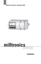
2.8 Measuring gas connection<br />
The measuring gas connection from the valve combination to the connection point (the centre of the retraction device) is<br />
implemented using a 3.5m long PTFE pressure hose of NW8 with metal braiding ( 2 ) and M16x1.5 union nuts at both ends.<br />
The PTFE pressure hose is screwed onto the bulkhead screwed gland ( 1 ) which is fixed to the connection point. A hose<br />
connection piece is fastened in the bulkhead gland, so that a PVC hose of ID 6mm ( 3 ) can be led further to the analysis<br />
equipment. ( See Figure 5 ).<br />
Legends:<br />
1 Bulkhead gland at connection point<br />
2 PTFE pressure hose<br />
3 PVC hose<br />
4 Analyzer cabinet<br />
5 Measuring gas connection on analysis<br />
6 Inserted probe<br />
7 Central traverse area<br />
8 Condensate vessel<br />
9 Condensate output<br />
10 <strong>Gas</strong> cooler device<br />
Fig. 5 Installation of the measuring gas line<br />
Copyright ® SIEMENS Page 14 04/04
SQ250 <strong>FLK</strong> <strong>Gas</strong> <strong>Sampling</strong> <strong>System</strong><br />
It should be ensured that the connection between the probe and the connection point with the probe inserted always slopes<br />
down ( no collection of condensate in "water pockets"). Also further on, the pipe must be laid as already stated either rising<br />
or falling towards the analysis device.<br />
With special analyses, such as for example SO 2 , a heated measuring gas line regulated thermostatically to approx. >150°C<br />
must be used. This line is then directly connected to the measuring gas output of the heated filter. It must be fixed with<br />
mounting clamps at the connection point and routed further up to the analysis equipment.<br />
Secure all hose connections with hose clamps (e.g. Norma or UNEX K010 Hose Connectors).<br />
To prevent mechanical damage, the measuring line can be laid in steel conduit or plastic ducting. It should be ensured that<br />
edges are rounded off or fitted with plastic edging.<br />
At points where there is a risk of frost the measuring line should be laid in an insulated plastic duct running in parallel with a<br />
heater pipe. The heater must be designed such that the measuring gas line (e.g. plastic pipe) is not damaged, but freezing is<br />
not possible.<br />
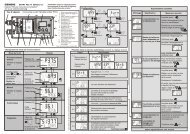
Keep the length and internal diameter (ID) of the measuring line as small as possible in order to prevent unnecessary dead<br />
time in the measurement; the display delay is dependent on the measuring gas flow (Figure 6) and on the length of the pipe<br />
(Figure 7).<br />
When laying the measuring gas lines, ensure absolute tightness of sealing, because otherwise extraneous air drawn in by the<br />
negative pressure will give erroneous measurements.<br />
Measuring gas<br />
flow<br />
For 1m gas line before the gas analysis device<br />
4 mm ID 7 mm ID 10 mm ID<br />
l/min sec. sec. sec.<br />
1,5<br />
1,6<br />
4,8<br />
9,6<br />
c<br />
1,0<br />
0,8<br />
2,4<br />
4,8<br />
b<br />
1,5<br />
0,6<br />
1,6<br />
3,2<br />
a<br />
2,0<br />
0,4<br />
1,2<br />
2,4<br />
Legends:<br />
a 4mm ID<br />
b 7mm ID<br />
c 10mm ID<br />
Fig. 6 Display delay in relation to the measuring gas flow<br />
Fig. 7 Display delay in relation to the length of measuring gas line<br />
2.9 Safety measures<br />
It is recommended that the area around the probe, including the traverse path, is closed off and provided with warning signs<br />
about the high temperature (up to 250° C) of the probe, coolant pipe and cooler as well as the automatic traversing.<br />
An emergency-stop button, included in the supplied items, can be fitted within this area, so that when it is operated the<br />
automatic probe traversing is stopped.<br />
Caution: When there is a power failure and a compressed air motor is used, the probe withdraws despite the<br />
EMERGENCY-STOP button being pressed on account of the compressed air.<br />
Copyright ® SIEMENS Page 15 04/04
SQ250 <strong>FLK</strong> <strong>Gas</strong> <strong>Sampling</strong> <strong>System</strong><br />
2.10 Electrical connections<br />
The electrical connections are implemented according to the regulations from the local power supply utility and of the<br />
relevant country.<br />
The cable for the connection of the devices is not included in the supplied items and should therefore be provided by the user<br />
according to our specifications. The required cable and the details about the cable connections can be taken from the wiring<br />
diagrams in the supplied wiring manual.<br />
However, it should be ensured that high flexibility, temperature resistant cables are used for the connection from the<br />
retraction device (valve combination). These must also be suitable for medium, mechanical stresses. In this respect particular<br />
care must be paid during laying (coolant operating temperature with hoses up to 250°C). The cables must not come into<br />
contact with any hot parts when the probe traverses.<br />
Control cables normally found in the relevant cement works can then be used from the connection point ( the centre of the<br />
retraction device ).<br />
The electrical supply cables on the heat exchanger unit are preferably implemented in steel conduit to the control cabinet.<br />
Here it should be ensured that these pipes are laid at a distance > 10cm from the hot pipes, the cooler and the coolant pump.<br />
Top laying is the preferred method for the feed cables.<br />
All cables must be lead into the cable entries provided in the control boxes.<br />
3. Operation<br />
3.1 General information<br />
A practical start-up should only be carried out during or after the raw-meal feed. However, the interchange of signals and the<br />
electrical functions can be checked beforehand.<br />
A temperature at the sampling point of at least approx. 600°C should be present for starting up the cooling circuit.<br />
Danger ! Probe and coolant lines have an operating temperature of up to 220° C!<br />
The baked-on deposits on the probe may have temperatures of over 1000° C!<br />
3.2 Start-up<br />
Warning!<br />
carried out.<br />
The probe must only be commissioned by qualified personnel who are familiar with all maintenance<br />
measures. Damage may occur if operated by unauthorized personnel and maintenance is improperly<br />
For safety reasons and guarantee considerations the initial start-up must always be carried out by<br />
SIEMENS or by persons that they have instructed.<br />
Copyright ® SIEMENS Page 16 04/04
SQ250 <strong>FLK</strong> <strong>Gas</strong> <strong>Sampling</strong> <strong>System</strong><br />
3.2.1 Electrical connections<br />
Once the electrical connections and connecting cable have been checked for correct laying, the mains voltages must be<br />
checked against the voltage figures given in the circuit documentation and against the name-plates.<br />
After switching on the voltage in the control cabinet and the PLC controller and after the input of the program the signal test<br />
based on the circuit documentation and the functional test can be started.<br />
Note:<br />
See also the operating manual for the controller, Chapter Start-up.<br />
Taken individually, the following signals should be checked:<br />
• Signals to the retraction device<br />
• Limit switch<br />
• The direction of rotation of the driving motor for the retraction device should be checked by a short pressing of<br />
contactor relay.<br />
• Check the function of the local operating panel with the manual / automatic switch.<br />
• Then briefly move the traversing carriage using the local control panel.<br />
Note:<br />
See also the operating manual for the retraction device, Chapter Start-up.<br />
• Signals for the valve combination<br />
• Control of the compressed air valves via counter using OP3<br />
• Control of the four-way ball valve (measure, close, blow out, test)<br />
• Operation of the low-pressure switch and setting to approx. 0,15 bar<br />
• Operation of the push-button, Purging ON and Purging STOP<br />
• Here it can be seen whether the purging starts and also stops.<br />
Note:<br />
See also the operating manual for the valve combination, Chapter Start-up.<br />
• Signals and supply for the measuring-gas filter heater<br />
• The thermal switch must switch off the heater after the operating temperature has been reached and<br />
a signal must be passed to the controller.<br />
Note:<br />
See also the operating manual for the measuring gas filter, Chapter Start-up<br />
• Signals to the analyzer cabinet<br />
• Flow bypass (for bypassing the flow monitor when the measuring gas pump is switched off)<br />
• "Purge" signal for fault-bypassing and limit-bypassing the analysis devices during purging.<br />
Note:<br />
See also the operating manual for the analyzer cabinet and the circuit documentation.<br />
Copyright ® SIEMENS Page 17 04/04
SQ250 <strong>FLK</strong> <strong>Gas</strong> <strong>Sampling</strong> <strong>System</strong><br />
• Signals to the heat exchanger unit<br />
• Before the motor protective switch in the control cabinet for the heat exchanger unit is switched on, the<br />
control signals must be checked by operating the separate contactors.<br />
• After switching in the main switch on the left side of the control cabinet and closing the protective switch, the<br />
direction of rotation of the blower and the circulation pump can be checked by momentary pressing the<br />
corresponding contactor relays.<br />
Note:<br />
See also the operating manual for the heat exchanger unit, Chapter Start-up.<br />
After termination of the signal test, the sealing check test and the flow check of the measuring gas line should take place. To<br />
do this, a method of changing certain counter values has been provided in the PLC program. See the Chapter Servicing, flow<br />
and sealing tests.<br />
3.2.2 Compressed air<br />
After the check of the compressed air hose and the retraction device with the probe installed, the compressed air can be fed<br />
with the shut-off valves closed.<br />
When using the retraction device with emergency retraction by a compressed air motor, the direction of rotation of the<br />
compressed air motor must be checked by slowly opening the main shut-off valve on the valve combination. When no<br />
voltage is applied, the traverse carriage must withdraw from the kiln. The compressed air motor is stopped in the withdrawn<br />
state by the compressed air limit switch.<br />
The compressed air connections should be tight to minimize consumption.<br />
Note:<br />
For the limit switch settings and the start-up of the traverse carriage see the operating manual for the<br />
retraction device and the valve combination.<br />
3.2.3 Purging process<br />
The purging is started by:<br />
1. The "Start" push-button on the valve combination or in the controller (when the probe is withdrawn only with the<br />
automatic switch in "Manual");<br />
2. When the probe is inserted;<br />
3. Automatically after expiry of the waiting interval between two purgings ( CTR 1 or 2 );<br />
4. The negative pressure in the measuring gas line is too high.<br />
The purging process with compressed air can be checked by pressing the "Start" button on the valve combination.<br />
Once the purging has started, the four-way ball valve is set to the "CLOSED" position. Then the release of the cleaning cycle<br />
(compressed air cleaning) occurs. When finished, the four-way ball valve moves to the position "Blow out condensate". Then<br />
the collected condensate is blown out of the condensate vessels. After this period has expired the four-way ball valve moves<br />
through the "Test" position (pressure balancing of the measuring gas line) into the "Measure" position. Then a low pressure<br />
test occurs after the measuring gas pump has started. When this has terminated, the purging process finishes after a<br />
measurement bridging period.<br />
The purging can be terminated at any time with the "Stop" buttons on the valve combination and in the controller.<br />
With the cleaning cycle, special attention must be paid to the correct sequence for controlling the compressed air valves.<br />
Copyright ® SIEMENS Page 18 04/04
SQ250 <strong>FLK</strong> <strong>Gas</strong> <strong>Sampling</strong> <strong>System</strong><br />
The four-way ball valve is moved to the "Closed" position with the probe withdrawn.<br />
The measuring gas pump is only in operation with the probe inserted, when a minimum coolant temperature of 130°C has<br />
been reached and when the measuring gas filter has reached its operating temperature.<br />
3.2.4 Heat exchanger unit<br />
See also the operating manual for the heat exchanger unit.<br />
After checking the electrical functions, the signal interchange to the controller and the coolant lines, the following settings for<br />
the coolant circuit must be checked and adjusted.<br />
Settings on the limit monitor:<br />
Coolant temperature, min.: 130°C<br />
Fan starts at : 180°<br />
Coolant temperature, max.: 220°C<br />
Switching hysteresis 2°C<br />
Set value for three-way valve: 140°C<br />
The precise settings are derived from the operating values over a longer period of time and may vary from system to system.<br />
Note:<br />
Do not open the shut-off valves on the venting containers when the pump is stationary unless really<br />
necessary, because otherwise air will enter the closed coolant circuit.<br />
3.2.5 Probe with retraction device<br />
In order to be able to begin with the insertion of the probe, the parameters in the PLC controller must be checked according to<br />
the "Controller" operating manual.<br />
Danger: During automatic or manual traversing of the probe, no unauthorized personnel should be present in the<br />
immediate vicinity of the probe, the kiln connection pipe and the retraction device.<br />
Note: The "EXTERNAL" release must be present ("1" signal on the PLC Input 4.6).<br />
Then a start can be made on the insertion of the probe into the kiln or precalcination chamber.<br />
• Set the manual / automatic switch to manual;<br />
• Uninterrupted pressing of the button "Insert probe";<br />
It is essential to check the following:<br />
• all moving parts such as coolant hoses, measuring gas line and electrical feeders.<br />
• the open Kiln connection piece<br />
• the proper functioning of the dust blow-back system (TMR 3,4,11)<br />
• coolant flow (heat exchanger unit, Lamp H6), flow measurement always on max. indication<br />
• coolant level min. (heat exchanger unit, Lamp H7)<br />
• pump fault (heat exchanger unit, Lamp H2)<br />
Copyright ® SIEMENS Page 19 04/04
SQ250 <strong>FLK</strong> <strong>Gas</strong> <strong>Sampling</strong> <strong>System</strong><br />
If faults occur during insertion, then the probe must automatically withdraw after the insertion button is released. Insertion of<br />
the probe can only be restarted after rectification of these faults.<br />
Note:<br />
The probe must first be inserted manually and also after each retraction due to a fault.<br />
Some faults must be simulated to test the safety functions. This should be carried out at the point of their acquisition if<br />
possible. The red fault lamp flashes for each fault (exception: probe not on automatic) and after acknowledgement it becomes<br />
continuously illuminated. The associated text appears on the display of the OP3 Operator Panel.<br />
Since a safety interlock is involved here (danger of overheating the probe and coolant), these functions should be tested in<br />
"Automatic" and "Manual" modes.<br />
Caution:<br />
When simulating the faults on the heat exchanger unit, particular care should be taken that, for<br />
example, with a fault on the coolant flow, overheating of the probe and damage to it cannot occur.<br />
• The automatic retraction of the probe with electrical and pneumatic drives occurs with the following faults:<br />
- Supply to heat exchanger<br />
- Supply to heated filter<br />
- Fault on coolant blower<br />
- Coolant flow < min. (time-delayed)<br />
- Coolant level < min.<br />
- Overtemperature > 220 degrees (time-delayed)<br />
- Coolant pump switched off<br />
- Limit switch fault, four-way ball valve<br />
- Position error, four-way ball valve<br />
- Limit switch fault, probe inserted<br />
- Time exceeded during insertion / retraction<br />
• The automatic retraction of the probe with pneumatic drive occurs with the following faults:<br />
- for power failure<br />
- for protective tripping of the power supply to the PLC<br />
- tripping of the motor protective switch for the probe drive-motor<br />
If damp penetrates into the coolant due to the condensate or other effects, sudden gas bubble formation may occur when the<br />
coolant is heated, causing interruption of the flow and therefore retraction of the probe. This occurs mainly at temperatures of<br />
approx. 125°C. At approx. 200°C...240°C vaporization of the coolant may occur. Therefore, the coolant fluid must be<br />
subjected to these ranges during the initial start-up. The following procedure has proven suitable for obtaining these critical<br />
points:<br />
• Slightly open the cover of the expansion vessel;<br />
• Slightly open the venting tap for the pump and cooler;<br />
• With the pump running, briefly open the venting container. While doing this, hold the collection container under the<br />
outlet;<br />
• When the probe withdraws due to interruption in the flow, immediately start the pump again;<br />
• After rectification of the fault, immediately insert the probe again;<br />
• Close the venting tap on the cooler;<br />
• Close the cover on the coolant expansion vessel.<br />
Copyright ® SIEMENS Page 20 04/04
SQ250 <strong>FLK</strong> <strong>Gas</strong> <strong>Sampling</strong> <strong>System</strong><br />
If the coolant temperature briefly reaches 230°C, normally no more gas bubble formation occurs.<br />
Caution:<br />
The probe temperature and therefore the coolant temperature must only briefly attain 230°C since<br />
otherwise the probe may be damaged.<br />
When heating the coolant, all the flange joints and welded seams should be checked for sealing, since the coolant is<br />
substantially thinner at high temperature. Any leaks occurring must be immediately remedied. It is essential to retighten the<br />
screws on the flange joints after heating the cooling system.<br />
3.2.6 Measures for emergency-stop<br />
It is recommended that the area around the probe (including traversing path) is closed off and access to this area restricted to<br />
authorized personnel. Within this area an emergency-stop button, can be fitted which stops the automatic traversing of the<br />
probe when operated.<br />
Caution:<br />
If the emergency-stop button is pressed, a dangerous condition can arise. For example, if the probe is still in the<br />
hot range and a fault occurs causing overheating of the probe (coolant flow >min.).<br />
To prevent damage of the probe, the emergency-stop button (with latch) should be released<br />
as soon as possible.<br />
With power failure the compressed air motor is used to withdraw the probe, even thought the<br />
emergency-stop button is pressed.<br />
While ever the emergency-stop button is operated, the red fault lamps in the PLC controller and on the local control panel<br />
flash and cannot be cancelled.<br />
3.2.7 Automatic probe retraction<br />
In order to be able to test the automatic insertion and retraction in a short time the hours timer TMR 10 must be set to a<br />
minutes timer by entering 60, i.e. the interval for retraction and insertion is now counted in minutes instead of hours.<br />
The time up to the start of "Retraction" can be read in the CTR 6 after manual insertion and switching to automatic (enter a<br />
minimum of 10min.).<br />
When this period expires, the horn and flashing light for the traverse warning turned on. When the horn time expires, the<br />
probe starts to retract. When the retraction is finished, the flashing light stops and the waiting period up to the re-insertion<br />
starts (TMR 0). Then the retraction warning starts and automatic insertion takes place.<br />
In this operating mode the signals, e.g. contactor fault (ESS INSERT, ESS WITHDRAW) and the time delay signals<br />
(DELAY INSERTION / RETRACTION) can be simulated.<br />
Once these tests are concluded, the TMR 10 must be set to 3600 sec. again.<br />
The required time interval for automatic insertion / retraction can be entered in the CTR 6 again in hours.<br />
The indicating lamps on the local control panel and on the controller flash if no analysis is not being carried out, i.e.: the<br />
measuring gas pump is switched off, also with the purging process running.<br />
Copyright ® SIEMENS Page 21 04/04
SQ250 <strong>FLK</strong> <strong>Gas</strong> <strong>Sampling</strong> <strong>System</strong><br />
4. Maintenance<br />
4.1 General information<br />
The following maintenance work must be carried out by the user to keep the equipment in an operational state: The sampling<br />
device, drive motor, traverse rails, valve combination and heat exchanger unit must be thoroughly cleaned of dust and dirt at<br />
least once per week.<br />
• When restarting the Kiln in the first month, the probe should be checked for baked-on deposits and damage each time it<br />
is withdrawn. and also when significant changes to the raw meal mixture occur.<br />
• Regular checking of the coolant circuit.<br />
• Compressed-air and measuring-gas lines, limit switches and particularly the moving parts must be checked for damage<br />
and repaired or renewed if necessary.<br />
- Checks to the cooling circuit<br />
• Here, the flow and level of the coolant fluid should be checked. If required, the coolant should be topped up. As an aid<br />
there is a level mark for 180°C on the expansion vessel. If this is undercut at the corresponding temperature, the<br />
coolant should be topped up.<br />
• If the level mark "min." is undercut in the hot condition, then it is essential to closely examine the cooling system for<br />
leakage. This may occur on the heat exchanger unit, connection hoses or on and in the probe.<br />
• Any unsealed points must be rectified as soon as possible.<br />
• If the flow indicator is no longer in the maximum range, the coolant filter must be removed and cleaned.<br />
The check of the measuring gas line is mainly just a visual check. Here, attention should be given to any water pockets,<br />
blockages or damage that has arisen.<br />
The flow in the analyzer unit should also be checked. A reducing flow indicates that the measuring gas lines are becoming<br />
choked.<br />
An interval of one week between checks is recommended.<br />
Note: Further maintenance measures can be taken from the operating manuals of the separate components.<br />
4.2 Optimizing the complete equipment<br />
It is imperative that optimization of the complete equipment is carried out after start-up.<br />
This can however only take place with normal operation of the kiln or precalcination facility and after the addition of the raw<br />
meal. Optimization involves the following points:<br />
4.2.1 Probe cooling circuit<br />
4.2.2 Automatic insertion / retraction of the probe<br />
4.2.3 Purging duration and interval<br />
Copyright ® SIEMENS Page 22 04/04
SQ250 <strong>FLK</strong> <strong>Gas</strong> <strong>Sampling</strong> <strong>System</strong><br />
4.2.1 Probe cooling circuit<br />
When the probe is inserted, its temperature increases very quickly. This temperature increase is firstly damped by the control<br />
of the three-way valve and secondly reduced by the cooling blower switching in, so that normally the temperature does not<br />
extend beyond 210..220°C. This temperature rise can be influenced by the set value on the three-way valve. Attempts should<br />
be made to obtain a working range of 135....215°C.<br />
If the coolant is very cold during insertion, then it takes a certain time until the three-way valve releases the coolant circuit<br />
via the cooler. Here, it may happen that the temperature increases above the maximum probe operating temperature, causing<br />
the probe to withdraw again. In this case the probe should be immediately inserted again after acknowledging the fault.<br />
In order to avoid this, the set value of the three-way valve must be reduced. In exceptional cases it is however possible to<br />
enter a delay time in the CTR 0 for the fault signal on a 10 sec. time grid.<br />
Note:<br />
If the delay time is too large, damage to the probe due to over-temperature may arise in certain situations.<br />
Due to the insulation effect of the baked-on deposits on the probe, the temperature range of the cooling circuit reduces. In<br />
order to obtain the longest possible service life of the probe in the kiln, the working temperature range should be as high as<br />
possible. To achieve this, the set value of the three-way valve should not be set below 145°C.<br />
4.2.2 Automatic retraction / insertion intervals for the probe<br />
The intensity of the baked-on deposits depends on a number of criteria, such as for example, the composition of the raw meal,<br />
installation location and fuel for the kiln heating, etc.<br />
If the baked-on deposits are too large, these cause high mechanical stresses in the probe and lead to an operating temperature<br />
that is too low.<br />
In order to regularly strip off the deposits on the probe, it can be automatically withdrawn after an interval entered in hours in<br />
the CTR 6. During this retraction period the deposits are cooled with compressed air and, where possible, blown back<br />
through the connection pieces into the hot area. The remaining deposits clinging to the probe cool down due to the waiting<br />
period which can be variably parameterized, so that with insertion again they are blown back by compressed air from the<br />
probe into the hot region.<br />
Depending on the intensity of the deposits on the probe, the interval between automatic retraction / insertion should be<br />
lengthened or shortened accordingly.<br />
If despite adaptation of this time interval the 130°C coolant temperature is undercut, then a once-only attempt to strip off the<br />
deposits from the probe is made by the automatic retraction / insertion.<br />
If the coolant temperature further undercuts the limit, the release of the analysis is withdrawn. The probe remains in the hot<br />
range until the time CTR6 has expired<br />
In this condition the probe must be "manually" withdrawn, cleaned and "manually" inserted again.<br />
4.2.3 Purging duration, purging interval<br />
See the controller operating manual for the purging procedure.<br />
Since dust deposits in the probe and filter are unavoidable, the purging process is initiated using an adjustable interval period.<br />
This timing interval should be maintained as long as possible, since no analysis is carried out during purging. On the other<br />
hand, the purging should be regularly initiated by a low-pressure signal.<br />
Copyright ® SIEMENS Page 23 04/04
SQ250 <strong>FLK</strong> <strong>Gas</strong> <strong>Sampling</strong> <strong>System</strong><br />
The purging duration should be kept as short as possible. However, it should be ensured that after purging, the low pressure,<br />
if present, returns to its normal value.<br />
It is therefore practical to match the purging duration and interval to local conditions.<br />
- Setting the purging duration<br />
• In order to prevent initiation of purging due to the expired purging interval time, this time must be temporarily set to a<br />
high value (CTR 1 to 300 minutes for example).<br />
• After approx. -0.08 bar is obtained, the purging process is started.<br />
• Then the low pressure is checked on the pressure gauge.<br />
• If the low pressure is the same as previously, then the purging duration (CTR 3) can be left as it is.<br />
- Setting the purging interval period:<br />
• In order to prevent initiation of purging due to the expired purging interval time, this time must be temporarily set to a<br />
high value (CTR 1 to 300 minutes for example).<br />
• Then it must be found how long it takes on average until the low pressure in the measuring gas line has reached approx.<br />
-0.08 bar. The low pressure can be read on the pressure gauge in the valve combination.<br />
• The time that has passed since the last purging can be read out from the CTR 1 in minutes using the OP3 Operating<br />
Panel.<br />
• The value obtained in minutes can now be entered in the CTR 1.<br />
• The limit contact in the pressure gauge for the release of the purging by low pressure should<br />
be set to -0.15 bar.<br />
If during longer operation an increasingly shorter purging interval period is found, then the low pressure must be checked<br />
directly after purging. If the low pressure does not correspond to the normal value and no fault can be found, the purging<br />
duration in the CTR 3 can be increased to 8 sec.<br />
4.3 Leakage test<br />
This should be carried out every six months or after each manual cleaning of the measuring gas line and after replacement or<br />
repair of various parts in the measuring gas line. ( pump, filter, gas cooler, etc.).<br />
To simplify the low-pressure ( leakage ) test of the complete system a method has been provided in the programmable logic<br />
controller of appropriately controlling the measuring gas four-way ball valve and the measuring gas pump.<br />
Here two procedures must be carried out:<br />
4.3.1. Leakage test between the four-way ball valve and the measuring gas pump<br />
4.3.2. Leakage test of the probe, filter and condensate vessel.<br />
When doing this, it is essential that the first test is correctly concluded and the sealing of the measuring gas connection is<br />
guaranteed.<br />
Copyright ® SIEMENS Page 24 04/04
SQ250 <strong>FLK</strong> <strong>Gas</strong> <strong>Sampling</strong> <strong>System</strong><br />
4.3.1 Leakage test between four-way ball valve and measuring gas pump.<br />
With this test the four-way ball valve is closed and the measuring gas pump switched on.<br />
This should always be carried out after a change of filter or any repairs to the measuring gas line, but in any case at least<br />
every six months.<br />
• Withdraw the probe.<br />
• Local control panel: Set the "Manual / Automatic" switch to "Manual".<br />
• In the PLC controller: By entering 16 in the CTR 16 the four-way ball valve moves to the "Closed" position and the<br />
measuring gas pump starts.<br />
• If a Siemens analyzer cabinet is being used, the pump will switch off due to the flow being too low.<br />
• This can be bypassed and a still larger negative pressure produced with the push-button "Pump on".<br />
• The negative pressure that has built up can be read from the pressure gauge in the valve combination. This should be<br />
approx. 0.3 .... 0.4 bar.<br />
• After the pump has switched off, the pressure drop should not exceed more than 2mbar after 3 minutes.<br />
• If this is not the case, then all connections should be retightened and, if necessary, the leaky points found and rectified.<br />
The leaky position can be narrowed down by constricting the measuring gas line from the pump side.<br />
4.3.2 Leakage test of the probe, filter and condensate vessel.<br />
With this test the four-way valve is moved to the "Measure" position and the measuring gas pump is switched on.<br />
This can only be carried out after a leakage test has been performed correctly under 4.3.1. Here, leakages between the probe<br />
and the four-way ball valve can be found ( including the measuring gas filter, condensate vessel and four-way ball valve ). If<br />
a heated measuring gas line is being used, this is also checked. This check should also be carried out at least every six<br />
months.<br />
• Withdraw the probe.<br />
• Local control panel: Set the "Manual / Automatic" switch to "Manual".<br />
• Switch off the filter heating and wait until the filter has cooled down (the waiting period can be shortened by starting the<br />
purging a number of times).<br />
• For a brief check it is sufficient to start the purging after applying a soap solution to all joints between the ball valve and<br />
the probe. Leaks can then be found by observing all the joints.<br />
• Close the probe at the sampling opening (only for initial start-up or probe replacement).<br />
Otherwise the connection between the probe and filter should be opened up. When doing this, loosen the fastening<br />
screws on the filter.<br />
• Close off the measuring gas input on the filter using stop-plugs.<br />
• In the PLC controller: By entering 15 in the CTR 16 the four-way ball valve moves to the "Measure" position and the<br />
measuring gas pump starts.<br />
• If a Siemens analyzer cabinet is being used, the pump is switched off, because the flow is too low.<br />
• This can be bypassed and a greater negative pressure produced with the "Pump on" push-button.<br />
• The negative pressure that has built up can be read from the pressure gauge in the valve combination. This should be<br />
approx. 0.3 .... 0.4 bar.<br />
Copyright ® SIEMENS Page 25 04/04
• When the pump has switched off, the drop in pressure must not be more than 2mbar in 3 minutes.<br />
Copyright ® SIEMENS Page 26 04/04
SQ250 <strong>FLK</strong> <strong>Gas</strong> <strong>Sampling</strong> <strong>System</strong><br />
• If this is not the case, all the joints, including the screws on the condensate container, should be evenly and carefully<br />
retightened. If necessary, find the leaky locations and rectify them.<br />
• Then restore the connection between the filter and the probe. Special attention should be given to the sealing tightness<br />
and correct mounting of the filter.<br />
4.4 Measures taken during a power failure<br />
When the power fails, the probe is withdrawn by a pneumatic motor. To achieve this, it is necessary to provide an adequate<br />
supply of compressed air. If no pneumatic drive is present or not enough compressed air is available, then it must be ensured<br />
that the probe is moved out of the hot region as quickly as possible - if necessary by rotating the coupling between the drive<br />
motor and gearbox. A hand crank can be used if possible.<br />
The coolant pump switches off when a power failure occurs and remains switched off until the power is restored.<br />
Note: Since the heat exchanger unit switches off during a power failure, a very dangerous state can arise if the<br />
probe is still in the hot region.<br />
The coolant is not circulated and overheating occurs. Due to the overpressure that builds up, very hot,<br />
thin coolant can be emitted from the probe, connection hoses or heat exchanger. Also, the complete probe may burn down.<br />
Therefore the probe should be supplied with either compressed air or with emergency power.<br />
4.4.1 Work necessary after the power is restored :<br />
• Start the coolant pump with the push-button (press until the flow has established).<br />
• Acknowledge the fault (PLC controller or local control panel).<br />
• Switch the controller to "Manual" and insert the probe manually.<br />
• When the probe has been inserted, a purging process is started automatically.<br />
• The measuring gas pump in the analyzer cabinet is started after the purging has terminated.<br />
• If the analyzer pump does not start, find the cause and manually start the pump.<br />
• Switch the controller to "Automatic".<br />
Copyright ® SIEMENS Page 27 04/04
SQ250 <strong>FLK</strong> <strong>Gas</strong> <strong>Sampling</strong> <strong>System</strong><br />
4.5 Measures to be taken during faults<br />
If a fault occurs and is acquired, the red fault lamp begins to flash quickly. While ever the fault is still present or has not been<br />
acknowledged (fault lamp flashes or is continuously illuminated), the relevant message text can be read in the control cabinet<br />
with the OP3 Operating Panel.<br />
Messag<br />
e<br />
No.<br />
Display text in<br />
operating panel<br />
Cause Effect Remedy<br />
0 Probe Emergency<br />
Stop<br />
Emergency stop button<br />
pressed<br />
Probe does not withdraw by<br />
electric motor, but instead<br />
pneumatically for a fault or<br />
power failure<br />
Important!: Dangerous condition during faults, e.g.<br />
coolant overtemp. cannot withdraw probe, risk of<br />
probe damage. For power failure, probe withdraws<br />
despite emergency-off; reset emergency-off, reset,<br />
insert probe.<br />
1 Control <strong>System</strong><br />
Fuse/Voltage fault<br />
Fuse failed<br />
Probe withdraws<br />
(el. +pneum.)<br />
Find cause of fuse failure and remedy, replace fuse,<br />
reset, insert probe<br />
2 Control <strong>System</strong> ESB<br />
S7 I4.2<br />
Power failure or fuse for<br />
PLC failed<br />
Probe withdraws<br />
pneumatically<br />
For fuse failure, find the cause and rectify it; after<br />
power is restored reset, insert probe<br />
3 Cooling <strong>System</strong> Flow<br />
< min<br />
Coolant flow too low<br />
(delayed 10s)<br />
Probe withdraws<br />
(electr. + pneum.)<br />
Coolant pump stops<br />
Check the coolant level, top up if required, check for<br />
leakage, manual valves must be open, start pump and<br />
vent, blocked oil filter. Reset, insert probe.<br />
4 Cooling <strong>System</strong><br />
Pump fault<br />
Power failure, flow too<br />
low, motor prot. switch<br />
tripped<br />
Probe withdraws<br />
(electr. + pneum)<br />
Find cause of motor prot. switch trip and rectify.<br />
Reset, start pump, insert probe<br />
5 Cooling <strong>System</strong> Fan<br />
fault<br />
Motor prot. switch<br />
tripped<br />
Probe withdraws<br />
(electr. + pneum.)<br />
Find cause of motor prot. switch trip and rectify.<br />
Reset, start pump, insert probe<br />
6 Cooling <strong>System</strong><br />
Level to low<br />
Coolant level too low<br />
Probe withdraws<br />
(electr. + pneum.)<br />
Find cause of coolant lost (leakage) and rectify; switch<br />
off pump, top up coolant, start pump, vent, reset, insert<br />
probe.<br />
Vent again when coolant temperature > 180 °C.<br />
7 Cooling <strong>System</strong><br />
Temperature to high<br />
Coolant temperature<br />
to high (default setting<br />
220°C)<br />
Probe withdraws<br />
(electr. + pneum.)<br />
Check coolant level and flow, vent, clean cooler, check<br />
GROW controller with 3-way valve, check limit<br />
setting on temp. controller. No obstacle in cooling air<br />
path? Rectify fault, reset, insert probe, vent again for<br />
coolant temp. > 170 °C<br />
8 Probe retraction<br />
Plugs not OK<br />
I 9.6 for plug monitoring<br />
(Valve combination not<br />
"1")<br />
Probe withdraws<br />
(electr. + pneum.)<br />
Check plug on valve combination for correct seating; if<br />
still not OK, check wiring, reset, insert probe<br />
9 <strong>Sampling</strong> <strong>Gas</strong><br />
Probe/Filter clog.<br />
Still low pressure in<br />
meas. gas line even after<br />
multiple purging<br />
(pressure switch)<br />
Probe does not withdraw.<br />
"Purging" lamp flashes at a<br />
fast rate<br />
Switch off filter heating fuse F1, start purging 3x to<br />
cool down filter, remove filter and clean, clean probe<br />
by undoing rear screw, also check line to condensate<br />
vessel and measuring gas lines, remover filter, ensuring<br />
absolute sealing tightness, switch on fuse F1.<br />
Check for leakage, reset Counter 16, insert probe.<br />
10 Probe retraction ESS<br />
Motor<br />
Either output for<br />
Contactor Insert or<br />
Contactor Withdraw is on<br />
and no feedback or<br />
output not on and<br />
feedback<br />
Probe withdraws<br />
(pneumatically)<br />
Check wiring, especially the limit switches which are<br />
directly latched to the corresponding contactor.<br />
Check outputs and inputs on the PLC:<br />
Output:<br />
Contactor Insert Probe<br />
Input: Feedback<br />
Output: Contactor Withdraw Probe<br />
Input: Feedback<br />
Reset, insert probe<br />
Copyright ® SIEMENS Page 28 04/04
SQ250 <strong>FLK</strong> <strong>Gas</strong> <strong>Sampling</strong> <strong>System</strong><br />
Messag<br />
e<br />
No.<br />
Display text in<br />
operating panel<br />
Cause Effect Remedy<br />
11 Probe Delaytime Out<br />
/ In<br />
Monitoring time<br />
exceeded for autom.<br />
insertion / retraction (110<br />
sec.)<br />
Check whether traverse device is jammed mech., poss.<br />
check motor wiring.<br />
Clean probe traverse device, traverse probe manually<br />
and ensure smooth running. Reset, insert probe.<br />
12 Probe-Limit<br />
Sw. fault<br />
Limit switches ”Probe<br />
In” and “Probe Out”<br />
simultaneously operated<br />
Probe withdraws<br />
(pneumatically)<br />
Clean limit switches and readjust as requ'd, ensure easy<br />
switching. Reset, insert probe.<br />
13 4-Way Valve<br />
Limit Sw.fault<br />
More than one input for<br />
the positions of<br />
4-Way valve = 0<br />
Probe withdraws<br />
(electr. + pneum.)<br />
Check in which position the 4-way valve is actually<br />
positioned and which additional input is "0". Check<br />
wiring and rectify fault. Reset, insert probe; Counter 16<br />
14 4-Way Valve<br />
Pos. fault<br />
4-way valve does not<br />
change its position<br />
within 20 sec. with<br />
driven motor.<br />
Probe withdraws<br />
(electr. + pneum.)<br />
Move valve manually and check, test wiring, measure<br />
voltage. If valve jams, remove, clean, reset, mount<br />
probe.<br />
15 Probe system not<br />
automatic<br />
Switch set on local<br />
control panel,<br />
not in “Automatic”<br />
Red "Fault" lamp is on, but<br />
does not flash<br />
Operating signal:<br />
Probe does not automatically move into / out of this<br />
position.<br />
Probe traversing only possible manually. With fault<br />
withdraws anyway.<br />
Control of 4-way and compressed air valves possible<br />
with operating panel.<br />
When automatic is selected, red lamp cancels itself if<br />
no other fault present.<br />
16 <strong>Sampling</strong> <strong>System</strong><br />
Filtertemp. < min<br />
Filter temperature is too<br />
low (
Copyright ® SIEMENS Page 30 04/04
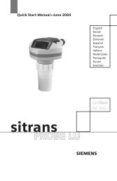
SQ251 <strong>FLK</strong> <strong>Gas</strong> <strong>Sampling</strong> Probe<br />
Fig. 1 <strong>FLK</strong> <strong>Gas</strong> <strong>Sampling</strong> Probe<br />
Contents Page Page<br />
1 Introduction ....................................................................... 33<br />
1.1 General information........................................................... 33<br />
1.2 Personnel qualification requirements................................ 33<br />
1.3 Field of application ............................................................ 33<br />
1.4 Construction and mode of operation ................................. 34<br />
1.5 Technical data................................................................... 35<br />
2 Installation ......................................................................... 36<br />
2.1 <strong>Gas</strong> sampling probe .......................................................... 36<br />
2.3 Coolant lines ......................................................................38<br />
2.4 Measuring gas connection.................................................39<br />
2.5 Covering flange..................................................................39<br />
3 Operation ...........................................................................40<br />
3.1 General information ...........................................................40<br />
3.2 Start-up ..............................................................................40<br />
4 Maintenance ......................................................................40<br />
Copyright ® SIEMENS Page 31 04/04
SQ251 <strong>FLK</strong> <strong>Gas</strong> <strong>Sampling</strong> Probe<br />
Note:<br />
We would like to point out that the content of this operating manual is not part of an earlier or existing agreement,<br />
consent, or a legal relationship nor should it be modified. All obligations on the part of SIEMENS can be taken<br />
from the relevant purchasing agreement which also contains the complete and solely valid warranty. These<br />
warranty provisions are neither extended nor restricted by this operating manual.<br />
We would also like to point out that for reasons of clarity not every conceivable problem situation in conjunction<br />
with the application of this product could be described in this operating manual. If you require further information<br />
or if particular problems occur which have not been dealt with in enough detail in the operating manual, you can<br />
request the required information via the local SIEMENS subsidiary.<br />
In the operating manual and in the warning information on the product, signal terms having the following meaning<br />
have been used:<br />
Danger as used in this operating manual and in warning information on the product itself means that death,<br />
severe injury and / or substantial material damage will occur if the appropriate precautions are not taken.<br />
Warning as used in this operating manual and in warning information on the product itself means that death,<br />
severe injury and / or substantial material damage can occur if the appropriate precautions are not taken.<br />
Caution as used in this operating manual and in warning information on the product itself means that slight injury<br />
and / or material damage can occur if the appropriate precautions are not taken.<br />
Note as used in this operating manual denotes an important item of information about the product or a relevant<br />
part of the operating manual requiring particular attention.<br />
Copyright ® SIEMENS Page 32 04/04
SQ251 <strong>FLK</strong> <strong>Gas</strong> <strong>Sampling</strong> Probe<br />
1. Introduction<br />
1.1 General information<br />
Warning!<br />
This system is operated by electricity. When operating electrical equipment, it is unavoidable<br />
that certain parts of this system carry a dangerous voltage.<br />
If the warning information is not followed, serious bodily injury and/or material damage may<br />
occur.<br />
Only appropriately qualified personnel should work on this equipment or in its vicinity. These<br />
persons must be thoroughly acquainted with all the warnings and maintenance precautions in<br />
accordance with this manual.<br />
The proper and safe operation of this device requires correct transport, storage, mounting<br />
and mounting as well as proper operation and maintenance.<br />
In particular the general construction and safety regulations about working on power<br />
installations (e.g. DIN, VDE) should be followed as well as the regulations relating to the<br />
proper use of lifting equipment and tools and the use of personal protective gear (protective<br />
goggles, etc.).<br />
1.2 Personnel qualification requirements<br />
As understood in this operating manual and on warning notices qualified personnel are persons who are<br />
acquainted with the mounting, mounting, maintenance and operation of this product and who possess appropriate<br />
qualifications for their occupation, such as for example covering:<br />
- training or instruction, and authorization for installing, removing, earthing and labelling power circuits,<br />
equipment and systems according to the currently valid standards of safety engineering,<br />
- training or instruction according to the currently valid standards of safety engineering in the care and use of<br />
adequate safety equipment;<br />
- training in first aid.<br />
This product left our factory in a perfectly safe condition. In order to maintain this condition and ensure the safe<br />
operation of the device, the information and warning notes given in this manual must be observed.<br />
1.3 Field of application<br />
The sampling probe is used for the continuous sampling of hot, aggressive and dust-laden flue gases such as<br />
NO, CO, CO 2<br />
, O 2<br />
and SO 2<br />
, from rotary kiln or precalcination chambers. It is an unpressurized, liquid-cooled, dry<br />
probe. The length of the probe can be adapted to different installation locations.<br />
Copyright ® SIEMENS Page 33 04/04
SQ251 <strong>FLK</strong> <strong>Gas</strong> <strong>Sampling</strong> Probe<br />
1.4 Construction and mode of operation<br />
The gas-sampling probe is basically constructed from four units:<br />
• sampling chamber,<br />
• cooling pipe with coolant return pipes,<br />
• gas sampling pipe,<br />
• mounting flange.<br />
Legends: 1. Connecting flange for coolant feed 5. Covering flange<br />
2. Connecting flange for coolant return 6. Cooling pipe<br />
3. Measuring gas output 7. <strong>Sampling</strong> chamber<br />
4. Mounting rail 8. <strong>Sampling</strong> opening<br />
Fig. 2 <strong>FLK</strong> <strong>Gas</strong> <strong>Sampling</strong> Probe<br />
The sampling chamber is located at the tip of the probe and has a sampling opening at the side. This arrangement<br />
of the opening prevents the direct entry of the gas / dust mixture. The opening is positioned in a partial gas flow<br />
and allows only relatively dust-free gas into the probe.<br />
The cooling pipe in high temperature-resistant special steel is hermetically enclosed and contains the coolant<br />
return pipe. The oval shape of the cooling pipe ensures a high vertical bending strength. The cooling liquid is<br />
carried to the probe tip via two feed pipes and flows back in the intervening space on the outer pipe. The two feed<br />
pipes are fastened at the probe head with a flange and can therefore be disassembled separately and without<br />
problem. A specially developed, synthetic heat transfer fluid is used as the coolant. This liquid has a very high<br />
boiling point and a high heat absorption capacity. The operating temperatures of over 200 °C obtained with the<br />
fluid are higher than the flue gas condensation point and acid dew point of the process gases. The coolant feed /<br />
return hoses are connected to the probe via ball valves, enabling the probe to be removed without loss of coolant.<br />
The gas-sampling pipe is a pipe arranged centrally in the cooling pipe at a distinct separation. The gas enters<br />
through an opening situated in the sampling chamber. This produces a slightly lower dust content in the gas.<br />
When high levels of contamination occur, this pipe can be easily cleaned. As with the two coolants return pipes,<br />
the gas-sampling pipe is joined to the cooling pipe via flange joints and can therefore be easily disassembled.<br />
The mounting flange provides the mechanical joint between the gas-sampling probe and the furnace inlet<br />
chamber or the precalcination chamber. When an automatic device is used for inserting and withdrawing the<br />
probe, the joint cannot be made using a screw-connected flange.<br />
Copyright ® SIEMENS Page 34 04/04
SQ251 <strong>FLK</strong> <strong>Gas</strong> <strong>Sampling</strong> Probe<br />
1.5 Technical data<br />
Type: F6534 -B12<br />
Lengths of different versions depending on penetration depth:<br />
3000 mm<br />
2500 mm<br />
2000 mm<br />
1500 mm<br />
1000 mm<br />
Type of sampling opening depending on installation orientation:<br />
E1 <strong>Sampling</strong> opening left<br />
E2 <strong>Sampling</strong> opening right<br />
( Viewed from coolant connection.)<br />
Operating temperature: max. 250°C<br />
Coolant:<br />
Coolant flow rate:<br />
Weight (filled with coolant):<br />
synthetic heat transfer liquid<br />
max. 3200 l/h<br />
approx. 150 kg depending on version<br />
Copyright ® SIEMENS Page 35 04/04
SQ251 <strong>FLK</strong> <strong>Gas</strong> <strong>Sampling</strong> Probe<br />
2 Installation<br />
2.1 <strong>Gas</strong> sampling probe<br />
The gas-sampling probe can basically be installed according to requirements, but the following possible methods<br />
should be considered.<br />
• On a manual retraction device.<br />
• On an automatic retraction device.<br />
It should be ensured however that the probe is mounted at an angle of about 5° sloping down to the probe tip.<br />
This prevents the formation of air bubbles in the probe.<br />
A fixed installation of the probe is not recommended.<br />
• Because if the cooling fails (also with power failure) and with cessation of the flow, dangerous coolant<br />
overheating may occur.<br />
• The weight of the probe is about 130 kg.<br />
• Excessive material deposits on the cooling pipe lead to increased mechanical loading and to excessive<br />
cooling of the cooling medium. When the cooling medium cools below the acid dew point, this leads to<br />
blockage of the sampling pipe. The probe would then have to be removed for cleaning.<br />
With an installation with a manual retraction device, appropriate mounting holes for the probe must be provided on<br />
the carriage together with mounting for the valve combination and the dust removal filter.<br />
Note:<br />
Installation plans must be requested from the relevant SIEMENS subsidiary.<br />
Mountings are provided for the probe, valve combination and dust removal filter for installation with an automatic<br />
retraction device.<br />
After mounting the retraction device, the probe is placed on the carriage and fastened to it (see Figure 3).<br />
See the separate operating manual for the installation of the retraction device.<br />
Copyright ® SIEMENS Page 36 04/04
SQ251 <strong>FLK</strong> <strong>Gas</strong> <strong>Sampling</strong> Probe<br />
Ansicht = View Sonde = Probe Detail = Detail<br />
Legends: 1 Cheese-head screw M12x60 5 Shim<br />
2 Cup spring 6 Hex. nut<br />
3 Spherical disc 7 Cheese-head screw M12x50<br />
4 Ball socket D14.2 8 Washer ø24xø13x10<br />
Fig. 3 Carriage and probe mounting (detail drawing)<br />
The probe must be aligned such that the cooling pipe is positioned with its tip about 1 cm over the centre of the<br />
inlet connection piece. To do this, traverse the probe until the tip penetrates a little into the inlet connection piece.<br />
The fine vertical adjustment of the probe is made with the cheese-head screw ( 7 ) and lock nut ( 6 ). Here, it<br />
should be ensured that the rear screws ( 1....5 Detail B ) are loosened. Once the probe has been aligned, tighten<br />
all screws, particularly the lock nut ( 6 ).<br />
Copyright ® SIEMENS Page 37 04/04
SQ251 <strong>FLK</strong> <strong>Gas</strong> <strong>Sampling</strong> Probe<br />
2.3 Coolant lines<br />
As supplied, the probe is already filled with coolant and the connecting flanges closed off with blank flanges. All<br />
screw fasteners and sealing gaskets for the flange joints are contained in the supplied items.<br />
Legends:<br />
1 Probe cooling pipe<br />
2 Return flange connection<br />
3 Feed flange connection<br />
4 Ball valve<br />
5 Seals<br />
6 Pipe bend 90°<br />
7 Connection flange for cooling<br />
line<br />
8 <strong>Gas</strong> output<br />
9 Cleaning opening<br />
10 Dust removal filter<br />
2<br />
Fig. 4 Connection of the coolant lines to the probe<br />
After removing blank flanges on the feed and return, the shut-off valves must be joined using flanges. If the<br />
coolant hoses are connected at the side, it is advisable to fit the 90° pipe bends after the shut-off valves and<br />
before the coolant hoses.<br />
Caution !<br />
Only the supplied special gaskets should be used between all the flange joints.<br />
The flanges must be tightened in a crosswise manner to obtain uniform compression of the gaskets.<br />
The connections between the probe and the fixed-mounted venting containers is made using flexible corrugated<br />
hoses NW 25, 3m long.<br />
The question of the mounting of the venting containers is dependent on the probe traverse distance. Normally,<br />
this mounting point is the centre of the traverse distance and at about 50cm distance from the connecting flanges.<br />
This should be the highest point of the coolant line. It should be accessible during traversing using a ladder or<br />
similar aid.<br />
See the section on mounting the complete analysis equipment with the <strong>FLK</strong> Probe for determination of the<br />
mounting points and coolant line arrangement.<br />
Copyright ® SIEMENS Page 38 04/04
SQ251 <strong>FLK</strong> <strong>Gas</strong> <strong>Sampling</strong> Probe<br />
2.4 Measuring gas connection<br />
A special, short hose with ERMETO unions, included in the supplied items for this purpose, is used for the<br />
measuring gas connection. After mounting the dust removal filter, the hose is connected between the filter and the<br />
probe.<br />
See the operating manual for the dust removal filter regarding mounting and alignment.<br />
2.5 Covering flange<br />
The covering flange seals the mounting flange to the inlet chamber or the precalcination chamber when the probe<br />
is inserted.<br />
Aussparung = recess<br />
Fig. 5 Covering flange<br />
flange<br />
Fig. 6 Mounting on the probe<br />
Legend: 1 fixing screw 3 covering<br />
2 gas sampling probe 4 lock nut<br />
Push the covering flange over the probe up to the probe mounting. Insert the probe up to the measuring position<br />
until the traversing is switched off by the limit switch. Push the covering flange onto the inlet connecting piece and<br />
centre it. Here it should be ensured that the recess on the covering flange runs exactly parallel to the runner rail.<br />
This prevents the covering flange from touching the limit switch during retraction and insertion. Always tighten<br />
opposite fastening screws alternately. Briefly insert and withdraw the probe a few times and check that the flange<br />
is well seated. During retraction check the distance between the covering flange and the limit switch. It must be at<br />
least 6mm. Readjust the covering flange if required and tighten the fastening screws. Then tighten the lock nuts.<br />
Note:<br />
Caution !<br />
When the furnace or precalcination chamber is heated up, slight offsets may arise between the<br />
installation flange and the traversing device due to expansion. It may be necessary to readjust the<br />
covering flange.<br />
If the probe is traversed with a covering flange that is not fastened down, then it is essential to<br />
ensure that the flange does not jam against the limit switch or runner rail.<br />
Fill the space between the covering flange mounting and the cooling pipe with temperature resistant insulation<br />
material.<br />
Copyright ® SIEMENS Page 39 04/04
SQ251 <strong>FLK</strong> <strong>Gas</strong> <strong>Sampling</strong> Probe<br />
3 Operation<br />
3.1 General information<br />
Danger !<br />
The probe and coolant lines have an operating temperature of up to 220° Cel.<br />
The baked-on deposits on the probe can reach temperatures of over 1000° Cel.<br />
3.2 Start-up<br />
Warning!<br />
The probe must only be operated by qualified personnel who are familiar with all maintenance<br />
measures. Damage may occur if operated by unauthorized personnel and maintenance is<br />
improperly carried out.<br />
See the operating manual for the complete gas analysis equipment with <strong>FLK</strong> Probe for the start-up procedures.<br />
4 Maintenance<br />
The following maintenance work must be carried out by the user to maintain the probe ready for operation:<br />
When using the probe on the furnace inlet, checks must be made in the initial period during each insertion and<br />
retraction. A check should be made of whether the baked-on deposits on the probe are released by compressed<br />
air during insertion. This opportunity should be used to check the probe for mechanical damage (e.g. due to falling<br />
material deposits in the furnace inlet chamber).<br />
The probe and coolant line connections should also be checked for leaking coolant.<br />
Any leaks must be immediately repaired.<br />
If the baked-on deposits are not released on insertion, then the probe must be cleaned manually.<br />
Danger !<br />
The probe and coolant lines have an operating temperature of up to 220° Cel.<br />
The baked-on deposits on the probe can reach temperatures of over 1000° Cel.<br />
With other installation locations (precalcination chamber) a regular check of the probe for damage, baked-on<br />
deposits and leakage on the coolant line connections must be carried out. The period between these checks<br />
should not exceed 14 days.<br />
If the sampling chamber and/or the sampling pipe becomes blocked, the probe must be cleaned manually. Once<br />
the screwed gland on the sampling side has been removed, the sampling pipe can be cleaned with a suitable rod<br />
or strong wire.<br />
If cleaning is no longer possible, the complete sampling pipe must be changed.<br />
If the ball valve becomes leaky, the tap spindle and/or seals must be replaced.<br />
Copyright ® SIEMENS Page 40 04/04
SQ252 Electrically Heated Dedusting Filter<br />
Fig. 1 Electrically heated dedusting filter<br />
Contents Page Page<br />
1 Introduction..................................................................................43<br />
1.1 General information.....................................................................43<br />
1.2 Personnel qualification requirements ..........................................43<br />
1.3 Field of application......................................................................44<br />
1.4 Construction.................................................................................44<br />
1.5 Mode of operation........................................................................46<br />
1.6 Technical data ..............................................................................48<br />
2 Installation ...................................................................................49<br />
2.1 General information.....................................................................49<br />
2.2 Mounting on the retraction device...............................................50<br />
3 Operation......................................................................................52<br />
3.1 General information.....................................................................52<br />
3.2 Start-up.........................................................................................52<br />
4 Maintenance................................................................................. 53<br />
4.1 General information..................................................................... 53<br />
4.2 Leakage test ................................................................................. 53<br />
4.2.1 Pressure test ................................................................................. 53<br />
4.2.2 Low pressure test......................................................................... 53<br />
4.2 Cleaning the filter or replacing the filter tube............................. 54<br />
4.3 Replacing the thermostat ............................................................. 55<br />
4.4 Measures for fault rectification ................................................... 55<br />
4.4.1 Filter does not reach operating temperature after<br />
about 15min................................................................................... 55<br />
4.4.2 No release of the measuring gas pump........................................ 55<br />
4.4.3 Filter becomes blocked too quickly ............................................ 55<br />
Copyright ® SIEMENS Page 41 04/04
SQ252 Electrically Heated Dedusting Filter<br />
Note:<br />
We would like to point out that the content of this operating manual is not part of an earlier or existing agreement, consent, or<br />
a legal relationship nor should it be modified. All obligations on the part of SIEMENS can be taken from the relevant<br />
purchasing agreement which also contains the complete and solely valid warranty. These warranty provisions are neither<br />
extended nor restricted by this operating manual.<br />
We would also like to point out that for reasons of clarity not every conceivable problem situation in conjunction with the<br />
application of this product can be described in this operating manual. If you require further information or if particular<br />
problems occur which have not been dealt with in enough detail in the operating manual, you can request the required<br />
information via the local SIEMENS subsidiary.<br />
In the operating manual and in the warning information on the product, signal terms having the following meaning have been<br />
used:<br />
Danger as used in this operating manual and in warning information on the product itself means that death, severe injury and<br />
/ or substantial material damage will occur if the appropriate precautions are not taken.<br />
Warning as used in this operating manual and in warning information on the product itself means that death, severe injury<br />
and / or substantial material damage can occur if the appropriate precautions are not taken.<br />
Caution as used in this operating manual and in warning information on the product itself means that slight injury and / or<br />
material damage can occur if the appropriate precautions are not taken.<br />
Note as used in this operating manual denotes an important item of information about the product or a relevant part of the<br />
operating manual requiring particular attention.<br />
Copyright ® SIEMENS Page 42 04/04
SQ252 Electrically Heated Dedusting Filter<br />
1. Introduction<br />
1.1 General information<br />
Warning! This system is operated by electricity. When operating electrical equipment, it is unavoidable that<br />
certain parts of this system carry a dangerous voltage.<br />
If the warning information is not followed, serious bodily injury and/or material damage may<br />
occur.<br />
Only appropriately qualified personnel should work on this equipment or in its vicinity. These<br />
persons must be thoroughly acquainted with all the warnings and maintenance precautions in<br />
accordance with this manual.<br />
The proper and safe operation of this device requires correct transport, storage, mounting and<br />
mounting as well as proper operation and maintenance.<br />
In particular the general construction and safety regulations about working on power installations (e.g.<br />
DIN, VDE) should be followed as well as the regulations relating to the proper use of lifting<br />
equipment and tools and the use of personal protective gear (protective goggles, etc.).<br />
1.2 Personnel qualification requirements<br />
As understood in this operating manual and on warning notices qualified personnel are persons who are acquainted with the<br />
mounting, mounting, maintenance and operation of this product and who possess appropriate qualifications for their<br />
occupation, such as for example covering:<br />
- training or instruction, and authorisation for installing, removing, earthing and labelling power circuits, equipment and<br />
systems according to the currently valid standards of safety engineering,<br />
- training or instruction according to the currently valid standards of safety engineering in the care and use of<br />
adequate safety equipment;<br />
- training in first aid.<br />
This product left our factory in a perfectly safe condition. In order to maintain this condition and ensure the safe operation of<br />
the device, the information and warning notes given in this manual must be observed.<br />
Copyright ® SIEMENS Page 43 04/04
SQ252 Electrically Heated Dedusting Filter<br />
1.3 Field of application<br />
The dedusting filter is used to clean the gas / dust mixture extracted from the process space. The filter is not just for use in<br />
conjunction with the <strong>FLK</strong> Probe, but also for other fields of application. It is particularly suitable for dry, high temperature,<br />
dust-laden gases (2000 mg/m 3 dust content).<br />
The filter is heated electrically to about 200 °C to prevent the filter pores from becoming silted up or clogged by baked-on<br />
deposits.<br />
1.4 Construction<br />
The electrically heated dedusting filter is protected to IP55 according to DIN 40050 and is therefore dust-proof and hoseproof.<br />
The electrically heated dedusting filter mainly consists of the following parts (see also Figure 2):<br />
1. Electrical terminal box.<br />
2. Filter housing with heating and insulation.<br />
3. Compressed air connections for cleaning.<br />
4. Quick-release clip with tommy screw for manual cleaning of sintered-metal filter.<br />
5. Filter head with seals and sintered-metal filter.<br />
6. Measuring gas connection.<br />
The filter head and filter housing consist of corrosion-resistant material and are joined to a central tommy screw via a<br />
retaining clip. Therefore when necessary, all maintenance work such as filter replacement, filter cleaning, etc. can be carried<br />
out easily and in the shortest time. Sealing is provided by high temperature-resistant O-rings which also give reliable sealing<br />
even after disassembling many times.<br />
By choosing an appropriate sintered-metal cylinder with different sizes, the filter element can be adapted to the relevant<br />
amount of dust.<br />
The dedusting filter is heated by the heating element integrated into the filter housing. The maintenance of a constant internal<br />
filter temperature, matched to the probe operating temperature, is ensured by a thermostat with overload protection mounted<br />
on the filter housing.<br />
All connections for the filter heating, thermostat and solenoid valve are brought together in a terminal box. The connection<br />
for the measuring gas line to the gas sampling probe is situated in the upper part of the filter housing.<br />
The compressed air connection for the probe cleaning is located on the bottom of the filter housing.<br />
An adjustable angular screwed gland with a connecting thread M16x1.5 is provided on the filter head for the measuring gas<br />
output.<br />
The compressed air connection for the filter cleaning can also be found on the filter head.<br />
Copyright ® SIEMENS Page 44 04/04
Legends:<br />
1 Electrical terminal box<br />
2 Filter housing with heater and insulation<br />
3 Compressed air connections for cleaning<br />
4 Quick-release clip with tommy screw<br />
5 Sealing plate with cup springs and nut<br />
6 Sintered-metal filter<br />
7 Filter head with seal for sintered-metal filter and housing<br />
8 Compressed air connection for filter purging<br />
9 Measuring gas inlet<br />
1O Measuring gas output<br />
Fig. 2 Construction of the electrically heated dedusting filter<br />
Copyright ® SIEMENS Page 45 04/04
SQ252 Electrically Heated Dedusting Filter<br />
1.5 Mode of operation<br />
The measuring gas to be cleaned flows from above into the space between the filter body and housing and is drawn from here<br />
through the filter body into the internal space in the filter. It is then taken from the filter head via the measuring gas output.<br />
Due to an equipment arrangement that is favourable to the flow, the dust-laden gas flow is not deflected. The dust particles<br />
separate on the outer side of the filter and fall by gravity to the bottom of the filter housing.<br />
The filter is electrically heated to about 200 °Cel to prevent the filter pores from becoming silted up or clogged by baked-on<br />
deposits.<br />
A voltage-free contact (normally open) is available for locking purposes. This enables the release of the measuring gas demand<br />
only after the operating temperature has been reached. This prevents the formation of condensate when the filter heater fails or<br />
at the start of operation.<br />
For higher availability, cleaning of the filter from dust deposits is particularly important.<br />
This cleaning is carried out using compressed air. Before starting cleaning, the measuring gas line for the analysis must be<br />
reliably shut off with a valve. Two cleaning cycles are recommended which can be employed independent of one another or in<br />
combination.<br />
Cleaning Cycle 1 (see Figure 3, arrow labelled 1) eliminates compacted dust particles in the pores of the filter tube (Figure<br />
3, Item 4). Here, the compressed air flows through the hot filter tube against the direction of the gas. The compressed air<br />
enters the filter tube via the connection on the filter head (Figure 3, Item 82) and is diverted via the probe connection<br />
(Figure 3, Item 80) into the furnace. The dust, which has become lodged in the pores of the filter tube, is now deposited on<br />
the bottom of the filter housing. However, with the flow through the filter tube there is an unavoidable pressure drop, which<br />
prevents the dust particles located in the filter chamber from being fully flushed back into the furnace.<br />
With Cleaning Cycle 2 (see Figure 3, arrow labelled 2) the compressed air is diverted through an annular jet (Figure 3, Item<br />
81) uniformly over the complete internal space of the filter chamber. The high air flow rate therefore has sufficient pressure<br />
to blow back (Figure 3, Item 80) the dust which has collected in the filter chamber into the furnace via the probe<br />
connection. Simultaneously, the gas sampling pipe and the sampling chamber with opening are cleaned from dust deposits.<br />
The activation of the cleaning can be matched to the specific furnace conditions in conjunction with the valve combination and<br />
the programmable control and monitoring unit.<br />
Copyright ® SIEMENS Page 46 04/04
Fig. 3 Cross-sectional drawing of electrically heated dedusting filter<br />
Legends: 1 Filter head 80 Measuring gas connection from probe<br />
2 Sealing gasket 81 Compressed air connection for probe flushing<br />
3 O-ring 82 Compressed air connection for filter flushing<br />
4 Filter tube 83 Measuring gas output<br />
5 Cup spring 84 Filter chamber<br />
6 Retaining washer<br />
7 Hexagonal nut<br />
8 Retaining tube<br />
9 Heater<br />
10 Dedusting filter<br />
11 Mounting bracket<br />
12 Terminal box<br />
13 Thermostat<br />
14 Tommy screw<br />
15 Retaining clip<br />
16 T-union with M24x1.5 connection<br />
Copyright ® SIEMENS Page 47 04/04
SQ252 Electrically Heated Dedusting Filter<br />
1.6 Technical data<br />
Electrical supply data:<br />
230V, 240V + 10%,-15% ; 50...60 Hz<br />
Power rating 400VA<br />
Compressed air supply data:<br />
6...8 bar<br />
Compressed air free from oil, dust and water<br />
Compressed air connections: Probe flushing: R 3/4" DIN<br />
Filter flushing:<br />
R 1/2" DIN<br />
Measuring gas connections: Measuring gas output: External thread M16x1.5 DIN<br />
Measuring gas input: External thread M24x1.5 DIN<br />
Thermostatic auxiliary contact:<br />
Temperature resistant -20 to +250 ºCel.<br />
Switching capacity max 40A at 250V, 50...60 Hz, cosϕ =1,0<br />
Operating temperature:<br />
max 210 ºCel<br />
Weight:<br />
6 kg<br />
Copyright ® SIEMENS Page 48 04/04
SQ252 Electrically Heated Dedusting Filter<br />
2 Installation<br />
2.1 General information<br />
The filter operating temperature is about 200 ºCel, so make sure that there is a sufficient distance to heat-sensitive parts.<br />
The electrically heated filter is constructed such that it can be easily mounted on the retraction device. If no retraction device is<br />
being used, then mounting on a mounting frame is also possible.<br />
The installation orientation is vertical. The measuring gas inlet must be at the top and the compressed air, measuring gas outlet<br />
and retaining clip must be at the bottom.<br />
A mounting bracket is attached to the upper cover plate. It has two elongated holes in its vertical section for M10 screws. These<br />
can be used to mount the filter.<br />
If no compressed air flushing is being used, the compressed air connections should be closed off with suitable screw-plugs.<br />
Fig. 4 Filter with mounting bracket<br />
Legends:<br />
1 Dedusting filter<br />
2 Electrical terminal box<br />
3 Measuring input for probe M24x1.5 ( Version on 90° or 45° possible)<br />
4 Mounting bracket<br />
5 Allen screws for fastening the mounting bracket<br />
6 Thermostat for auxiliary contact<br />
7 Thermostat for electrical heater<br />
Copyright ® SIEMENS Page 49 04/04
SQ252 Electrically Heated Dedusting Filter<br />
2.2 Mounting on the retraction device<br />
A suitable mounting fixture with mounting holes is available on the retraction device for the <strong>FLK</strong> Probe.<br />
The required joining parts are included with the supplied items (supplementary pack). All connections have been implemented<br />
such that confusion is eliminated.<br />
During mounting the filter should be aligned such that the measuring gas connection is positioned at the same height as the<br />
probe connection. Before final mounting the PTFE pressure hose NW12 with steel braiding and TEFLON core must be<br />
adapted and screwed with the ERMETO M24x1.5 unions and the tapered rings.<br />
The mounting fixture is designed such that the filter can be correctly aligned in both height and depth.<br />
Note: When routing the hoses pay particular attention to the absolute sealing of the measuring gas line. See also the<br />
general operating manual Chapter 2.5, Mounting the probe with retraction device.<br />
After mounting, the other connections for compressed air, measuring gas outlet and the electrical connections must be made.<br />
• Connecting the valve combination to the filter:<br />
• Compressed air for probe flushing. Stainless steel corrugated hose 3/4" with braiding with R 3/4" unions on both<br />
ends<br />
• Compressed air for filter flushing. Stainless steel corrugated hose 1/2" with braiding with R 1/2" unions on both<br />
ends<br />
The connection from the filter to the condensate separator is implemented in TEFLON pipe or with PTFE pressure<br />
hose depending on the version.<br />
• TEFLON pipe: In this case the PTFE screw-on gland for pipe connection is screwed onto the adjustable angular<br />
screw gland on the filter. The PTFE angular screw-in gland is screwed into the condensate separator. These must<br />
joined to the TEFLON pipe such that the TEFLON pipe does not break off and runs slightly sloped to the<br />
condensate separator.<br />
Note:<br />
All screwed joints for the measuring gas must be sealed with TEFLON.<br />
• PTFE pressure hose: This PTFE pressure hose is fitted with M 16x1.5 union nuts at both ends. These are used to<br />
directly connect the PTFE pressure hose to the screw couplings on the filter and condensate vessel.<br />
If an electrically heated measuring gas line is used between the probe and analysis cabinet, then this must<br />
directly connected to the filter. The ERMETO couplings included in the supplied items can be used for this.<br />
be<br />
• For the electrical connection, the ready-made lead with plug is attached to the filter terminal box.<br />
This only needs to be plugged into the appropriate socket on the valve combination.<br />
Copyright ® SIEMENS Page 50 04/04
SQ252 Electrically Heated Dedusting Filter<br />
1<br />
7<br />
2<br />
6<br />
11<br />
4<br />
3<br />
5 10 12<br />
8, 9<br />
Fig. 5 Installation of the filter on the retraction device<br />
Legends:<br />
1 <strong>FLK</strong> Probe<br />
2 Retraction device<br />
3 Valve combination<br />
4 Dedusting filter<br />
5 Electrical terminal box<br />
6 Mounting bracket<br />
7 Measuring gas connection, probe / filter<br />
8 Compressed air connection, probe flushing<br />
9 Compressed air connection filter flushing<br />
10 Measuring gas connection, filter / condensate vessel<br />
11 Pipe bend 90º<br />
12 Condensate vessel<br />
13 Shut-off ball valve (not shown)<br />
Copyright ® SIEMENS Page 51 04/04
Siemens<br />
SQ252 Electrically Heated Dedusting Filter<br />
3 Operation<br />
3.1 General information<br />
Danger !<br />
The electrically heated filter has an operating temperature of up to 210° Cel.<br />
3.2 Start-up<br />
Warning! The electrically heated filter must only be operated by qualified personnel who are familiar with all the<br />
maintenance measures. Unauthorised operation and improperly carried out starting procedures can cause damage.<br />
After inspecting the electrical connections and also the connecting cable for correct routing, a check should be made of<br />
whether the mains voltage agrees with the voltage specified in the wiring documentation and on the name-plate.<br />
The leakage test should be carried out as in Section 4.2.<br />
After switching on the voltage, the function of the thermostat should be checked. The heater must switch off when the<br />
operating temperature is reached.<br />
The auxiliary contact for switching on the measuring gas pump must switch over at about 180 °Cel.<br />
Copyright ® SIEMENS Page 52 04/04
Siemens<br />
SQ252 Electrically Heated Dedusting Filter<br />
4. Maintenance<br />
4.1 General information<br />
With automatic cleaning using compressed air no regular work is needed by the user. However, checks for any damage and<br />
external soiling should be made in conjunction with other maintenance work and remedied if necessary.<br />
4.2 Leakage test<br />
4.2.1 Pressure test<br />
This test is always required after mounting as well as installation and removal of the filter head.<br />
• Seal off absolutely tight the measuring gas input to the filter (a blank plug can be used for this).<br />
• It is sufficient for a short test when using the valve combination to start the flushing and observe whether compressed<br />
air escapes anywhere on the filter.<br />
Note: With small leaks it is recommended that leak-seeking spray or soap solution is applied to the joints to<br />
localise any leaks.<br />
• This opportunity can also be used to test the joints on the measuring gas line up to the four-way valve.<br />
• Any leaks which are found should be rectified.<br />
4.2.2 Low pressure test<br />
Since the filter is normally under negative pressure in operation, a sealing test under negative pressure is more conclusive.<br />
• Close off the measuring gas input on the filter as under 4.2.1.<br />
• Connect a low pressure measurement sensor as close as possible to the filter output. Ensure absolute sealing tightness!<br />
• Produce a negative pressure of about 300 mbar by switching on the measuring gas pump.<br />
• Shut off the line. The low pressure must now remain almost constant (pressure drop in 5 minutes max. 2 mbar).<br />
• Localise any leaks and rectify them.<br />
Copyright ® SIEMENS Page 53 04/04
Siemens<br />
SQ252 Electrically Heated Dedusting Filter<br />
4.3 Cleaning the filter or replacing the filter tube<br />
The filter should be removed and cleaned If an excessively large negative pressure occurs at the filter, or, when a valve<br />
combination is used, the filter flushing is often initiated by the low pressure, or at the latest after the signal "Filter / probe<br />
blocked" occurs.<br />
Careful - danger of burning !<br />
Electrically heated filter has an operating temperature of up to 210° Cel.<br />
See Figure 3 for the procedure<br />
• Switch off the fuse for the filter heater or unplug the plug for the filter on the valve combination.<br />
• Start the compressed air flushing, if available, a few times to cool the filter.<br />
• Loosen and remove the hoses on the filter head at the filter end (compressed air connection, Item 82 and measuring gas<br />
connection, Item 83).<br />
• Loosen the tommy screw (Item 14) on the retaining clip (Item 15).<br />
• Swivel the retaining clip to the side.<br />
• Withdraw the filter head (Item 1) with the filter tube (Item 4) downwards.<br />
• Loosen the screw (Item 7), retaining it with a mandrel.<br />
• Remove the cup springs (Item 5) and retaining washer (Item 6).<br />
• Remove the filter tube (Item 4) and clean it inside and outside with a brush and compressed air.<br />
With obstinate soiling, the filter tube can be cleaned with a suitable chemical solvent.<br />
However, if the filter tube is mechanically damaged or cleaning is no longer possible, then it must be replaced.<br />
• Before fitting the cleaned or new filter tube, check the O-rings (Item 3) for sealing on the front side of the filter tube and<br />
the sealing gasket (Item 2) on the filter head, renewing them if required.<br />
• Replace the filter tube, place the retaining washer (Item 6) and the cup springs (Item 5) flat, tighten with screw (Item 7)<br />
and retain using the mandrel. Make sure that the filter tube does not become misaligned.<br />
• Replace the filter insert and fasten with the retaining clip and tommy screw.<br />
• Blow out the gas lines from the filter to the probe sampling chamber as well as the condensate vessel with compressed<br />
air or clean them by hand.<br />
• Reconnect the hoses, ensuring sealing tightness.<br />
• Carry out a leakage test according to Section 4.2.1.<br />
• Plug in the electrical connectors and switch on the heater fuse.<br />
Copyright ® SIEMENS Page 54 04/04
Siemens<br />
SQ252 Electrically Heated Dedusting Filter<br />
4.4 Replacing the thermostat<br />
• Switch off the fuse for the filter heater or withdraw the plug for the filter on the valve combination.<br />
• Start the compressed air flushing a few times, if available, to cool the filter.<br />
• Loosen the electrical connection cable in the terminal box (Item 12) and pull back the cable.<br />
• Remove the thermostat after loosening the screws at the top of the filter.<br />
• Smear the new thermostat with heat conducting paste on the bottom and firmly screw to the filter.<br />
• Insert the cable into the terminal box and connect according to the wiring diagram.<br />
• Carry out a functional test.<br />
4.5 Measures for fault rectification<br />
4.5.1 Filter does not reach operating temperature after about 15min.<br />
• Check the voltages in the terminal box.<br />
• If there is no voltage on the heater, replace the thermostat.<br />
• If voltage is present on the heater, replace the heater or the complete filter housing.<br />
4.5.2 No release of the measuring gas pump<br />
• Check that the filter operating temperature is about 200 ºCel.<br />
• Check the voltages in terminal box.<br />
• If the temperature is still too low after about 15 min., carry out procedure in 4.4.1.<br />
• If the operating temperature is reached, but thermostat not closed for release, replace the thermostat.<br />
4.5.3 Filter becomes blocked too quickly<br />
If the filter becomes blocked soon after cleaning:<br />
• Check whether the release for the measuring gas pump only occurs after reaching the operating temperature.<br />
• Replace auxiliary-contact thermostat. Procedure as in 4.3.<br />
• Is there enough compressed air available for flushing?<br />
• Check the compressed air pressure and check supply line if necessary.<br />
• Is there compressed air available as required (free of oil and dry) ?<br />
• Check the filter tube for blocked pores (black, burnt deposits).<br />
Note: If oil compounds are present in the compressed air, then baked-on deposits which are difficult to<br />
remove occur in the filter tube. The tube can then only be replaced.<br />
Copyright ® SIEMENS Page 55 04/04
Siemens<br />
SQ253 Valve Combination<br />
Copyright ® SIEMENS Page 56 04/04
Siemens<br />
Fig. 1 Valve combination for mounting on the retraction device<br />
Copyright ® SIEMENS Page 57 04/04
Siemens<br />
SQ253 Valve Combination<br />
Contents Page Page<br />
1. Introduction.......................................................... 59<br />
1.1 General information ............................................ 59<br />
1.2 Personnel qualification requirements ................ 59<br />
1.3 Field of application .............................................. 60<br />
1.4 Construction......................................................... 60<br />
1.5 Mode of operation................................................ 62<br />
1.6 Technical data ...................................................... 63<br />
2. Installation............................................................ 64<br />
2.1 General information ............................................ 64<br />
2.2 Mounting on the withdrawal device................... 64<br />
2.2.1 Hose connections to the withdrawal<br />
mechanism..................................................................... 64<br />
2.2.2 Cable connection to the withdrawal<br />
device ............................................................................. 65<br />
2.3 Compressed air/measuring gas<br />
connection/ ext. cable<br />
connection ............................................................. 65<br />
3. Operation.............................................................. 66<br />
3.1 General information ............................................ 66<br />
3.2 Start-up................................................................. 66<br />
3.2.1 Electrical start-up ................................................ 66<br />
3.2.2 Compressed air and leakage test ........................ 66<br />
4. Maintenance ......................................................... 67<br />
4.1 General information ......................................... 67<br />
4.2 Compressed air filter ........................................ 67<br />
4.3 Compressed-air solenoid valves....................... 68<br />
4.3.1 Replacing the valves.......................................... 69<br />
4.3.2 Cleaning the valve ............................................. 69<br />
4.3.3 Faults:................................................................. 69<br />
4.4 Condensate separator ....................................... 69<br />
4.5 Four-way ball valve........................................... 71<br />
4.5.1 Removing the 4-way ball valve ........................ 71<br />
4.5.1.1 Checking and setting the limit switches:......... 70<br />
4.6 Low-pressure pressure switch.......................... 71<br />
4.7 Electrically operated compressed air<br />
valve (option) ................................................................ 71<br />
4.7.1 Replacing the valve ........................................... 71<br />
4.7.2 Cleaning a valve: ............................................... 71<br />
4.7.3 Faults:................................................................. 71<br />
4.8 Pneumatically operated compressed air<br />
valve (option) ................................................................ 72<br />
4.8.1 Replacing the valve ........................................... 72<br />
4.8.2 Cleaning the valve:............................................ 72<br />
Note:<br />
We would like to point out that the content of this operating manual is not part of an earlier or existing agreement, consent, or<br />
a legal relationship nor should it be modified. All obligations on the part of SIEMENS can be taken from the relevant<br />
purchasing agreement which also contains the complete and solely valid warranty. These warranty provisions are neither<br />
extended nor restricted by this operating manual.<br />
We would also like to point out that for reasons of clarity not every conceivable problem situation in conjunction with the<br />
application of this product could be described in this operating manual. If you require further information or if particular<br />
problems occur which have not been dealt with in enough detail in the operating manual, you can request the required<br />
information via the local SIEMENS subsidiary.<br />
In the operating manual and in the warning information on the product, signal terms having the following meaning have been<br />
used:<br />
Danger as used in this operating manual and in warning information on the product itself means that death, severe injury and<br />
/ or substantial material damage will occur if the appropriate precautions are not taken.<br />
Warning as used in this operating manual and in warning information on the product itself means that death, severe injury<br />
and / or substantial material damage can occur if the appropriate precautions are not taken.<br />
Caution as used in this operating manual and in warning information on the product itself means that slight injury and / or<br />
material damage can occur if the appropriate precautions are not taken.<br />
Note as used in this operating manual denotes an important item of information about the product or a relevant part of the<br />
operating manual requiring particular attention.<br />
Copyright ® SIEMENS Page 58 04/04
Siemens<br />
SQ253 Valve Combination<br />
1. Introduction<br />
1.1 General information<br />
Warning!<br />
This system is operated by electricity. When operating electrical equipment, it is unavoidable that certain<br />
parts of this system carry a dangerous voltage.<br />
If the warning information is not followed, serious bodily injury and/or material damage may<br />
occur.<br />
Only appropriately qualified personnel should work on this equipment or in its vicinity. These<br />
persons must be thoroughly acquainted with all the warnings and maintenance precautions in<br />
accordance with this manual.<br />
The proper and safe operation of this device requires correct transport, storage, mounting and<br />
mounting as well as proper operation and maintenance.<br />
In particular the general construction and safety regulations about working on power installations (e.g.<br />
DIN, VDE) should be followed as well as the regulations relating to the proper use of lifting<br />
equipment and tools and the use of personal protective gear (protective goggles, etc.).<br />
1.2 Personnel qualification requirements<br />
As understood in this operating manual and on warning notices qualified personnel are persons who are acquainted with the<br />
mounting, mounting, maintenance and operation of this product and who possess appropriate qualifications for their<br />
occupation, such as for example covering:<br />
- training or instruction, and authorization for installing, removing, earthing and labelling power circuits, equipment and<br />
systems according to the currently valid standards of safety engineering,<br />
- training or instruction according to the currently valid standards of safety engineering in the care and use of<br />
adequate safety equipment;<br />
- training in first aid.<br />
This product left our factory in a perfectly safe condition. In order to maintain this condition and ensure the safe operation of<br />
the device, the information and warning notes given in this manual must be observed.<br />
Copyright ® SIEMENS Page 59 04/04
Siemens<br />
SQ253 Valve Combination<br />
1.3 Field of application<br />
The valve combination is used for the automatic cleaning of <strong>FLK</strong> <strong>Gas</strong> <strong>Sampling</strong> Probes which are mainly used for measuring<br />
gas sampling up to approx. 1800 °C with a high dust content.<br />
Due to the high dust concentration in the process gas, dust deposits in the sampling probe and in the heated filter are<br />
unavoidable. Therefore, automatic, cyclical cleaning has been implemented for the probe and the filter. The mechanical parts<br />
required for this are accommodated in the valve combination. If a compressed air motor is being used for the "emergency<br />
withdrawal" of the probe, the control valves needed for the motor are also in the valve combination.<br />
Note:<br />
See also the general operating manual for the <strong>FLK</strong> Probe.<br />
1.4 Construction<br />
The valve combination is designed as a compact unit (see Figure 2). All the parts required for flushing, the valve unit for the<br />
control of the compressed air motor (Item 4, optional), and the drive motor for the four-way ball valve (Item 10) are<br />
accommodated so that they are protected from dust, splashing water and from mechanical damage. A compressed air filter<br />
with automatic condensate drain is connected in front of the filter in the compressed air line. Maintenance-free ball tap (Items<br />
2) are provided for shutting off the compressed air during maintenance work. The compressed air filter and the ball tap are<br />
fitted on the outside so that easy operation and cleaning are possible.<br />
The buttons for starting and stopping the flushing are located on the front panel.<br />
With this construction the valve combination should only be opened in case of a fault or for maintenance work.<br />
A condensate vessel is fitted on the side before the four-way ball valve for retaining the condensate arising after the<br />
electrically heated filter.<br />
Note:<br />
If a heated line is being used for passing the measuring gas between the probe and the analysis cabinet, the<br />
condensate vessel (Item 9), four-way ball valve (Item 10) and low-pressure pressure switch are located in the<br />
analysis cabinet so that the heated line can be cleaned when flushing.<br />
Copyright ® SIEMENS Page 60 04/04
Siemens<br />
SQ253 Valve Combination<br />
Fig. 2 Valve combination<br />
Legends:<br />
1 Coupling for compressed air connection<br />
2 Manual shut-off ball valve<br />
3 Pneumatic valve for compressed air motor<br />
4 Electrically operated valve for compressed air motor<br />
5 Solenoid valves for probe flushing<br />
6 Solenoid valves for filter flushing<br />
7 Compressed air connection for probe flushing<br />
8 Compressed air connection for filter flushing<br />
9 Condensate precollector<br />
10 Electrically driven four-way ball valve<br />
11 Connection terminals for all electrical connections for the trunk<br />
cable to the controller<br />
12 measuring gas input from probe<br />
13 Teflon hose<br />
14 Measuring gas output to analyzer<br />
Copyright ® SIEMENS Page 61 04/04
SQ253 Valve Combination<br />
1.5 Mode of operation<br />
In conjunction with an PLC programmable logic controller, the compressed air valve combination carries out the appropriate<br />
cleaning program for the flushing of the gas sampling system. Dry compressed air, free of dust and oil, is required at 6...8 bar.<br />
The consumption depends on the duration of cleaning and on the compressed air pressure.<br />
The compressed air for the cleaning is passed via the filter (Figure 2) with automatic condensate separator.<br />
For safety reasons manual shut-off ball tap are provided in the filter feed for shutting off the compressed air during<br />
maintenance work, etc.<br />
The low-pressure in the measuring gas line between the measuring gas input on the probe, the four-way ball valve and the<br />
measuring gas pump in the analysis cabinet is measured with the pressure switch. This low pressure is a measure of the<br />
contamination in the probe, dust removal filter and following measuring-gas line to the measuring gas pump. With a blockage<br />
in these areas the measuring gas pump produces a negative pressure and if this exceeds the set limit, flushing is started<br />
irrespective of the set flushing interval period.<br />
The condensate occurring in front of the valve combination is collected in an enclosed glass vessel.<br />
The motor-driven four-way ball valve releases the measuring gas path when the probe is inserted and when no faults are<br />
present in operation.<br />
If a measuring cycle is started, the four-way ball valve moves to the "Closed" position. The measuring gas line is therefore<br />
closed, so that no compressed air can enter the analysis cabinet. Now the solenoid valves for the filter flushing (Figure 2,<br />
Item 6) are controlled cyclically. The compressed air is blown into the probe through the inner side of the filter in a pulsating<br />
manner. Shortly before the termination of the filter flushing, the solenoid valves for the probe flushing (Figure 2, Item 5) are<br />
also switched. This cleans the filter pipe from the outer side and also the probe. After termination of the filter / probe<br />
flushing, the compressed air valves are closed and the four-way ball valve turns further into the position "Blow out<br />
condensate". Then the solenoid valves are controlled once again so that the condensate is blown out of the condensate vessel.<br />
Pressure compensation with respect to atmospheric pressure then takes place in the "Test" position.<br />
Note:<br />
See the operating manuals for the PLC controller, <strong>FLK</strong> probe and electrically heated filter for further details on<br />
flushing.<br />
When using the withdrawal device with a compressed air motor, the following valves are also accommodated for the<br />
emergency withdrawal of the probe.<br />
1. Solenoid valve which opens in the unenergized state and therefore switches on the compressed air motor.<br />
2. Pneumatically operated valve which switches off the compressed air motor via a pneumatic limit switch when the<br />
probe withdraws.<br />
For all the electrical connections to the withdrawal device (drive motor, limit switch) and to the electrically heated filter<br />
(heater and thermostat) coded connectors are provided on the bottom. These enable quick mounting and rapid replacement of<br />
defective parts. The terminal strip in the valve combination is provided for the connection of the flexible, heat resistant trunk<br />
cable to the control cabinet.<br />
Copyright ® SIEMENS Page 62 04/04
SQ253 Valve Combination<br />
1.6 Technical data<br />
Electrical supply<br />
Voltage:<br />
110 – 230VAC + 24VDC<br />
Compressed air supply<br />
Supply pressure<br />
6 ... 8 bar,<br />
Dry, free of dust and oil<br />
Permissible ambient temperature:<br />
0 ... 60°Cel.<br />
Dimensions:<br />
630 mm x 380 mm x 210 mm<br />
Type of protection: IP 54 to DIN 40050<br />
Weight:<br />
25kg<br />
Pressure switch :<br />
Display range<br />
Two way contact<br />
Contact rating<br />
-300 ... -700 mbar<br />
max.: 250V AC, 1,5A / 24DC, 2A<br />
4-way valve:<br />
24 VDC<br />
Actuating time for 90°<br />
approx. 20sec<br />
Compressed air filter: Max operating pressure 25 bar<br />
Max. temperature 90 °C<br />
Filter element<br />
sintered metal<br />
Pore size 30 µm<br />
Draining<br />
automatic<br />
Solenoid valves: Max operating pressure 0...16 bar<br />
Max. temperature 80 °C<br />
Copyright ® SIEMENS Page 63 04/04
SQ253 Valve Combination<br />
2. Installation<br />
2.1 General information<br />
The valve combination is constructed such that it can be easily mounted on the withdrawal device. If no withdrawal device is<br />
being used, then fixing on a mounting frame is possible. Documentation for this can be requested from the SIEMENS<br />
company in the relevant country.<br />
2.2 Mounting on the withdrawal device<br />
The valve combination is fastened to the four screw bolts provided on the opposite side of the drive motor on the traversing<br />
carriage.<br />
All internal connecting screws on the measuring gas line must be retightened, including the nuts on the condensate vessel<br />
(Figure 2, Item 11). Once the valve combination has been mounted, the hose and cable connections to the withdrawal device<br />
and the electrically heated filter must be made.<br />
Note:<br />
See general operating manual Chapter 2.5, Mounting the probe with withdrawal device.<br />
The joining hardware needed for this is included in the supplied items (supplementary pack). All connections have been<br />
labeled to eliminate confusion.<br />
2.2.1 Hose connections to the withdrawal mechanism<br />
These consist of:<br />
Connections between valve combination and electrically heated filter<br />
• Metal-braided hose with R 3/4" threaded joint at both ends for compressed air for the probe flushing.<br />
• Metal-braided hose with R 1/2" threaded joint at both ends for compressed air for the filter flushing.<br />
• Depending on the measuring gas connection between filter and condensate vessel (Figure 2, Items 11,20):<br />
PTFE pressure hose with union nuts (M16x1.5) on both ends.<br />
TEFLON pipe for high-corrosion version with TEFLON screwed glands.<br />
Note: Special attention should be paid to ensure that the PTFE pressure hose or the TEFLON pipe continuously<br />
slopes down to the condensate vessel.<br />
Connections for the compressed air motor. ( Figure 2, View A. ):<br />
• Compressed air feed line to the pneumatic limit switch connection M16x1.5<br />
Valve combination "P2" to the pneumatic limit switch "R1/P2"<br />
• Return line from pneumatic limit switch connection M16x1.5<br />
Valve combination "A" to the pneumatic limit switch "A"<br />
• Compressed air feed line to the compressed air motor connection M16x1.5<br />
Copyright ® SIEMENS Page 64 04/04
SQ253 Valve Combination<br />
2.2.2 Cable connection to the withdrawal device<br />
The electrical connection from the withdrawal device and the electrically heated filter are implemented in ready-made cable<br />
to the terminal strip in the valve combination (Figure 2, Item 14). The connections are:<br />
• electrically heated filter<br />
• limit switch, Probe Withdrawn<br />
• limit switch, Probe Inserted<br />
• Drive motor for withdrawal device<br />
2.3 Compressed air/measuring gas connection/ ext. cable connection<br />
A quick-release coupling to DIN 3483 is provided for the compressed air connection (Figure 2, Item 1). The NW20<br />
compressed air line must be connected to this.<br />
The measuring gas connection (Figure 2, Item 18) is made via the ready-made, 3.5m long PTFE pressure hose with metal<br />
braiding. This is directly screwed to the angular screwed joint. No further sealing with TEFLON is needed due to the conical<br />
nipple connection on the hose.<br />
The electrical connections are implemented according to the regulations of the local power supply utility and of the relevant<br />
country.<br />
The cables between the valve combination and the controller are not included in the supplied items and must therefore be<br />
supplied to our specifications by the user. The required cable and the details about the cable connections can be taken from<br />
the wiring diagrams in the supplied wiring manual.<br />
The cables must be routed through the provided M screwed glands, sealed and again clamped. The fixtures for the cables,<br />
measuring gas lines and compressed air hose should be produced by the user depending on the installation. See Figure 3 for<br />
examples.<br />
Note:<br />
See general operating manual Chapter 2.10, Electrical connections.<br />
< 1 > < 2 > < 3 > < 4 > < 8 > < 8 > < 9 ><br />
< 6 ><br />
Fig. 3 Suggested fastenings for holding the feed lines.<br />
Legends: 1 Valve combination 6 Flat bar 30 x 4 mm<br />
2 Fastening screw M8 7 Fastening for compressed air hose<br />
3 Cable retention bracket 8 Pipe clamp<br />
4 Fastening for measuring gas hose 9 Plastic cable protection<br />
5 Fastening for control cable 10 M screwed gland for control cable ( Underside )<br />
Copyright ® SIEMENS Page 65 04/04
SQ253 Valve Combination<br />
3. Operation<br />
3.1 General information<br />
This equipment unit has been supplied functionally tested. Therefore, no complicated checks of the separately installed<br />
devices are needed.<br />
3.2 Start-up<br />
Warning! The valve combination in conjunction with the withdrawal device must only be put into operation by<br />
qualified personnel, who are familiar with all maintenance measures. Unauthorized operation and improperly carried out<br />
start-up procedures can cause damage.<br />
The start-up is mainly restricted to a check of the wiring, a functional check and a leakage test of the complete measuring<br />
equipment.<br />
3.2.1 Electrical start-up<br />
After checking the wring to the control cabinet, the following functional checks can be carried out. These should be done<br />
before the compressed air is switched on.<br />
• The individual settings on the four-way valve should be selected from the PLC controller using the OP3<br />
Operating Panel.<br />
• Similarly, the function of the compressed air valves -Y2, -Y3, -Y4, and -Y5 should be checked.<br />
• It must also be checked whether the flushing is initiated and started by the local push buttons. The flushing<br />
process must also be started by simulating low pressure (turning back the limit switch contacts to -300 mbar).<br />
• The flushing sequence must be checked according to the sequence in the operating manual for the controller.<br />
3.2.2 Compressed air and leakage test<br />
With the compressed air it must be ensured that the 6...8 bar pressure, the quantity and the quality conform to the<br />
specification.<br />
Caution:<br />
There should be no one situated in the front area of the probe.<br />
The compressed air must be shut off immediately if any leaks occur.<br />
Turn-on should be carried out slowly and special attention must be paid to the joining pieces.<br />
The compressed air part with the valves should be checked for sealing tightness (use leak-seeking spray or soap-water<br />
solution as an aid).<br />
After starting the flushing, the connecting lines to the filter and the probe should be tested for sealing tightness once the leakseeking<br />
agent has been applied.<br />
If a compressed air motor is being used on the withdrawal device, the function of the withdrawal valves must be checked.<br />
• In the unenergized state the solenoid valve (Figure 2, Item 5) must be open and the compressed air motor driven.<br />
• When the pneumatic limit switch on the withdrawal device is operated, the pneumatic valve (Figure 2, Item 4)<br />
closes and shuts off the compressed air feed to the motor.<br />
Note: The solenoid valve must close absolutely tight when energized, because otherwise the traverse carriage will<br />
move slowly in operation.<br />
Copyright ® SIEMENS Page 66 04/04
SQ253 Valve Combination<br />
4. Maintenance<br />
4.1 General information<br />
The user should carry out the following maintenance work so that operational readiness is ensured:<br />
• The valve combination must be thoroughly cleaned of dust and dirt every week.<br />
• The compressed air filter should be cleaned every month.<br />
• A leakage test of the complete system (compressed air side and measuring gas side) must be carried out every six<br />
months.<br />
4.2 Compressed air filter<br />
The compressed air filter is used for the effective separation of liquid and solid particles from the compressed air. However, it<br />
is not intended for oil separation.<br />
The air flows in the direction of the arrow through the filter and is made turbulent by the<br />
guide vane A. The particles of liquid are thrown against the internal walls and run<br />
downwards. The separating cap B forms a calm zone which prevents the separated<br />
condensate from being taken up again by the air flow. Then the air flows through the filter<br />
element C. Here all solid contaminants are retained which are larger than the pore size.<br />
When the condensate reaches a certain height, a valve is opened by the float F and the<br />
filter is automatically drained.<br />
With filters with manual drainage, the filter is drained by operating the drain screw E.<br />
Clean the compressed air filter at least once per month, more often if necessary.<br />
To do this, shut off the compressed air before the filter. Open the filter by turning<br />
the metal container to the right and then clean it.<br />
automatische/manuelle Entleerung<br />
automatic / manual drainage<br />
Fig. 4 Compressed air filter<br />
Copyright ® SIEMENS Page 67 04/04
SQ253 Valve Combination<br />
4.3 Compressed-air solenoid valves<br />
This 2/2 solenoid valve is closed in the unenergized state (action Type A).<br />
It is suitable for neutral gases and liquids which do not attack the housing material. The sealing material is labeled behind<br />
the nominal width on the name-plate (B = NBR, A = EPDM, F = FPM).<br />
Fig. 5 Compressed-air solenoid valve<br />
Copyright ® SIEMENS Page 68 04/04
SQ253 Valve Combination<br />
4.3.1 Replacing the valves<br />
• Pull off the cable head after loosening the screw.<br />
• Loosen screwed joints on the housing.<br />
• Unscrew the pipes at both ends.<br />
• Before fitting the new valve<br />
Note:<br />
Pay attention to voltage and type of current according to the nameplate.<br />
• Clean the pipe work of contamination (metal swarf, sealing material).<br />
Note: The arrow indicates the direction of flow. Do not use the valve as a lever when screwing it in. Do not block pilot hole<br />
on the valve output with pipe ends, sealing material, etc. Use PTFE tape as sealing material.<br />
• Assembly takes place in the reverse sequence.<br />
4.3.2 Cleaning the valve<br />
• Pull off the cable head after loosening the screw.<br />
• The pilot valve can be removed after loosening the four screws on the solenoid section.<br />
• Take care with the core and spring.<br />
• Loosen four screws on the valve cover.<br />
• Remove the upper part.<br />
• Take out the diagram and, if necessary, clean it and replace damaged parts.<br />
• The valve body can now be cleaned.<br />
• Grease with silicone grease or acid-free Vaseline.<br />
• Assembly takes place in reverse sequence.<br />
Note:<br />
Observe the tightening torque of 1Nm for the cable head.<br />
4.3.3 Faults:<br />
• Check connections. operating pressure and voltage.<br />
• Pilot hole on the valve output covered or contaminated ?<br />
Solenoid does not pull in:<br />
• Short circuit or coil interruption.<br />
• Core or core aperture contaminated.<br />
• With alternating current, jammed core causes coil overheating.<br />
Leaky valve:<br />
• Procedure as under Section 4.3.2<br />
SQ253 Valve Combination<br />
Copyright ® SIEMENS Page 69 04/04
SQ253 Valve Combination<br />
4.4 Condensate separator<br />
The condensate separator consists of a glass bulb, lower and upper cover plates in stainless steel each with a connection<br />
opening and O-rings between the glass bulb and covers. Since the condensate vessel is blown out with each flushing process,<br />
no maintenance work is required.<br />
When replacing the various parts, it should be ensured during assembly that the four threaded bolts with hexagon nuts are<br />
tightened evenly and that the O-rings are correctly seated.<br />
If any leaks occur:<br />
• First, slightly, but evenly tighten the threaded bolts.<br />
• Check the glass bulb for any damage.<br />
• Check the O-rings.<br />
Copyright ® SIEMENS Page 70 04/04
SQ253 Valve Combination<br />
4.5 Four-way ball valve<br />
The 4-way ball valve is constructed in steel with an electrical actuator drive to DIN ISO 5211/3337.<br />
The ball valve material is complete in PEEK. The full sealing tightness is achieved by a pressure-aided, maintenance-free<br />
sealing system.<br />
The actuator drive is also maintenance-free and fitted with an anti-blocking motor with temperature monitoring.<br />
4.5.1 Removing the 4-way ball valve<br />
• Remove inside the housing of the 4 Way-valve. Loosen the 2 screws inside the valve box and remove the valve<br />
from the drive.<br />
Note: Attention must be paid to the connecting cable. This is so long that the complete unit can be lifted<br />
out.<br />
4.5.1.1 Checking the limit switches:<br />
• Remove the complete unit as described above.<br />
• Check the position of the 4 limit switches<br />
• The control is provided by the OP3 in the control cabinet.<br />
• A selected position is approached by entry in the CTR 16 (e.g. Measure).<br />
• Assembly takes place in the reverse sequence.<br />
Important! When setting the limit switches, pay attention to the 24VDC control voltage.<br />
Copyright ® SIEMENS Page 71 04/04
SQ253 Valve Combination<br />
4.6 Low-pressure pressure switch<br />
When the filter or probe is contaminated or blocked, a negative pressure is built up by the measuring gas pump.<br />
The electrical contact device integrated into the pressure switch function for monitoring and starting the flushing process.<br />
The magnetic snap-action contact is suitable for harsh applications which place high demands on switching capacity.<br />
The low-pressure pressure switch is largely maintenance-free. With an erroneous indication or for no indication, the<br />
connecting hose should be cleaned or, if necessary, the complete pressure switch replaced.<br />
4.7 Electrically operated compressed air valve ( option )<br />
This compressed air valve is included when a compressed air motor is used for the emergency withdrawal on the withdrawal<br />
device.<br />
When the voltage is switched on, the solenoid is energized and the valve switches. The compressed air supply to the<br />
compressed air motor is shut off. The control is implemented directly from the control unit.<br />
This Type MCH-3-1/2 can be converted by rotating the seal under the cover to the other valve version Type MOCH-3-1/2.<br />
4.7.1 Replacing the valve<br />
• Pull off the cable head after loosening the screw.<br />
• Loosen the screwed joints on the housing.<br />
• Pull off the hose from both sides after opening the hose clamps.<br />
• Remove the valve.<br />
• Unscrew the screw-in hose nozzles and the reducing unions.<br />
• Before fitting the new valve<br />
Note:<br />
Pay attention to voltage and type of current according to the nameplate.<br />
• Clean the hose nozzles and use PTFE tape to seal the thread.<br />
• Screw in the hose nozzles into the new valve.<br />
• Assembly takes place in the reverse sequence.<br />
4.7.2 Cleaning a valve:<br />
• Pull off the cable head after loosening the screw.<br />
• Loosen the upper nut on the solenoid coil.<br />
• Remove solenoid coil.<br />
• Remove the cover after loosening the two screws.<br />
• Remove the plunger and diaphragm. Clean and replace damaged parts if necessary.<br />
• After removing the snap-ring on the bottom, the pilot valve can be removed.<br />
• Clean the valve body and replace any damaged parts.<br />
• Assembly takes place in the reverse sequence.<br />
Note: Pay attention to the tightening torque of 1Nm for the cable head.<br />
4.7.3 Faults:<br />
• Check connections, operating pressure and voltage.<br />
Solenoid does not pull in:<br />
• Short circuit or coil interruption.<br />
• Core or core aperture contaminated.<br />
• Jammed core causes coil overheating on alternating current.<br />
Copyright ® SIEMENS Page 72 04/04
SQ253 Valve Combination<br />
Leaky valve:<br />
• Procedure as in Section 4.7.2 or replace the valve.<br />
Fig. 7<br />
Electrically operated compressed air valve<br />
4.8 Pneumatically operated compressed air valve ( optional )<br />
This compressed air valve is only fitted when a compressed air motor is being used for the emergency withdrawal on the<br />
withdrawal device.<br />
The valve has, depending on the choice of connections, the function "no throughput when unenergized" (11 blocked, 2 to 33<br />
vented) or the function "throughput when energized (11 to 2, 33 blocked).<br />
The valve switches only for the duration of the signal on terminal 110 or 12.<br />
4.8.1 Replacing the valve<br />
• Loosen the screwed joints on the housing.<br />
• Pull off the hose after opening the hose clamps on both sides.<br />
• Remove the valve.<br />
• Unscrew the screw-in hose nozzles and the reducing unions.<br />
• Check the type of valve before fitting the new one.<br />
• Clean the hose nozzles, use PTFE tape for sealing the thread.<br />
• Screw in the new valve.<br />
• Assembly takes place in the reverse sequence.<br />
Copyright ® SIEMENS Page 73 04/04
SQ253 Valve Combination<br />
4.8.2 Cleaning the valve:<br />
• Release the two screws and remove the cover.<br />
• Take out the plunger and diaphragm and clean, and replace any damaged parts.<br />
• The pilot valve can be removed after removing the snap-ring on the bottom.<br />
• Clean the valve body, replacing any damaged parts.<br />
• Assembly takes place in the reverse sequence.<br />
Fig. 8 Pneumatically operated compressed air valve<br />
Copyright ® SIEMENS Page 74 04/04
SQ254 Heat Exchanger<br />
Fig. 1 Heat Exchanger<br />
Contents Page Page<br />
1. Introduction........................................................................ 76<br />
1.1 General information........................................................... 76<br />
1.2 Personnel qualification requirements ................................ 76<br />
1.3 Field of application ............................................................ 76<br />
1.4 Function description of the heat exchanger....................... 77<br />
1.5 Technical data ................................................................... 78<br />
2. Installation ......................................................................... 79<br />
2.1 Installation of the heat exchanger...................................... 79<br />
2.2 Electrical connection ......................................................... 79<br />
2.3 Filling up the heat exchanger with cooling liquid ............... 79<br />
3. Setting into operation......................................................... 80<br />
3.1 Safety specifications.......................................................... 80<br />
3.2 Preparation before first Start-up ........................................ 80<br />
3.3 Adjustment of temp.-controller in switch cabinet .............. 81<br />
3.3.1 Setpoint for temperature adjustment of the 3-WV ............. 81<br />
3.3.2 Setpoint for temp.adjustment of fan .................................. 81<br />
3.3.3 Min. limit value for start gas-sampling............................... 81<br />
3.3.4 Max. limit value emergency extraction of probe ................ 82<br />
3.4 Standard starting ............................................................... 82<br />
4. Setting out of operation ..................................................... 82<br />
4.1 Shutdown the equipment................................................... 82<br />
5. Maintenance...................................................................... 82<br />
Copyright ® SIEMENS Page 75 04/04
SQ254 Heat Exchanger<br />
Note:<br />
We would like to point out that the content of this operating manual is not part of an earlier or existing agreement,<br />
consent, or a legal relationship nor should it be modified. All obligations on the part of SIEMENS can be taken<br />
from the relevant purchasing agreement, which also contains the complete and solely valid warranty. These<br />
warranty provisions are neither extended nor restricted by this operating manual.<br />
We would also like to point out that for reasons of clarity not every conceivable problem situation in conjunction<br />
with the application of this product could be described in this operating manual. If you require further information<br />
or if particular problems occur which have not been dealt with in enough detail in the operating manual, you can<br />
request the required information via the local SIEMENS subsidiary.<br />
In the operating manual and in the warning information on the product, signal terms having the following meaning<br />
have been used:<br />
Danger as used in this operating manual and in warning information on the product itself means that death,<br />
severe injury and / or substantial material damage will occur if the appropriate precautions are not taken.<br />
Warning as used in this operating manual and in warning information on the product itself means that death,<br />
severe injury and / or substantial material damage can occur if the appropriate precautions are not taken.<br />
Caution as used in this operating manual and in warning information on the product itself means that slight injury<br />
and / or material damage can occur if the appropriate precautions are not taken.<br />
Note as used in this operating manual denotes an important item of information about the product or a relevant<br />
part of the operating manual requiring particular attention.<br />
Copyright ® SIEMENS Page 76 04/04
SQ254 Heat Exchanger<br />
1. Introduction<br />
1.1 General information<br />
Warning!<br />
This system is operated by electricity. When operating electrical equipment, it is unavoidable<br />
that certain parts of this system carry a dangerous voltage.<br />
If the warning information is not followed, serious bodily injury and/or material damage may<br />
occur.<br />
Only appropriately qualified personnel should work on this equipment or in its vicinity. These<br />
persons must be thoroughly acquainted with all the warnings and maintenance precautions in<br />
accordance with this manual.<br />
The proper and safe operation of this device requires correct transport, storage, mounting<br />
and mounting as well as proper operation and maintenance.<br />
In particular the general construction and safety regulations about working on power<br />
installations (e.g. DIN, VDE) should be followed as well as the regulations relating to the<br />
proper use of lifting equipment and tools and the use of personal protective gear (protective<br />
goggles, etc.).<br />
1.2 Personnel qualification requirements<br />
As understood in this operating manual and on warning notices qualified personnel are persons who are<br />
acquainted with the mounting, mounting, maintenance and operation of this product and who possess appropriate<br />
qualifications for their occupation, such as for example covering:<br />
- training or instruction, and authorization for installing, removing, earthing and labeling power circuits,<br />
equipment and systems according to the currently valid standards of safety engineering,<br />
- training or instruction according to the currently valid standards of safety engineering in the care and use of<br />
adequate safety equipment;<br />
- training in first aid.<br />
This product left our factory in a perfectly safe condition. In order to maintain this condition and ensure the safe<br />
operation of the device, the information and warning notes given in this manual must be observed.<br />
1.3 Field of application<br />
The heat exchanger is used for cooling the <strong>FLK</strong> gas sample probe for operation in the inlet of the rotary kiln at<br />
process gas temperatures up to 1400°C. The heat exchanger employs a synthetic heat transfer liquid as coolant.<br />
Copyright ® SIEMENS Page 77 04/04
SQ254 Heat Exchanger<br />
1.4 Function description of the heat exchanger<br />
The device is designed to operate the gas sampling probe and the sample gas at a temperature above the dew<br />
point of acids (appr. 130 °C).<br />
During the start up the coolant is bypassed by the three-way valve directly to the gas-sampling probe. After<br />
exceeding the setpoint of the minimum temperature for the closed position of the three-way-valve, the coolant is<br />
directed through the heat exchanger. This method ensures a short heating-up-time of the coolant. Sample gas will<br />
not be taken below the minimum temperature. A cooling fan is switched on at coolant temperatures above 180°C<br />
to force the cooling of the radiator. If the coolant temperatures drops below 180°C the cooling fan is switched off<br />
again.<br />
The level switch (6) monitors the “level minimum” in the expansion vessel. In case of low level of the liquid the<br />
circulating pump is switched off.<br />
For troubleshooting please refer to page 7, “level minimum”.<br />
The flow meter (4) monitors the flow of the coolant. If the minimum flow is less than the minimum for more than 5<br />
sec, the circulation pump is switched off and an alarm is generated. For troubleshooting please refer to page 7,<br />
“Flow”.<br />
For thermal overload protection the probe is being retracted from the kiln at coolant temperatures more than<br />
220°C.<br />
For troubleshooting please refer to page 7, “Exceed temperature”.<br />
Faults are indicated on the signal lamps on the cabinet. For further utilization it can be wired to a control system<br />
by means of potential free contacts.(wiring diagram G 3302-A3254-S004)<br />
Copyright ® SIEMENS Page 78 04/04
SQ254 Heat Exchanger<br />
1.5 Technical data<br />
Operating Voltage Volt 380-480<br />
Frequency Hz 50/60<br />
Control Voltage Volt 24 V DC from control unit<br />
Frequency Hz 50/60<br />
Cooling capacity kW 65<br />
Circulation pump<br />
Power of motor kW 2.2<br />
Motor speed 1/min 3460<br />
Fan<br />
Power of motor kW 0,52<br />
Motor speed 1/min 1340<br />
Heat exchanger<br />
Inlet temperature of air °C max. 45<br />
Outlet temperature of air °C appr. 105<br />
Inlet temperature of medium °C 200<br />
Outlet temperature of medium °C 170<br />
Cooling surface m 2 25<br />
Cooling unit<br />
Weight, incl. filling kg appr. 420<br />
Protection type IP 54<br />
Cooling medium<br />
synthetic heat transfer liquid<br />
Total content of the unit ltr. appr. 50<br />
The performance data mentioned above are guaranteed provided that Siemens approved heat transfer liquid is<br />
used as a cooling medium. Do not use other cooling medium than specified by Siemens.<br />
For service, power supply and serial number please refer to the nameplate on the switch cabinet.<br />
Factory Settings<br />
Temperature of thermostat to be adjusted for 3 way valve 140 °C<br />
Switch temperature for start fan to be adjusted at the Temp.-controller 180 °C<br />
Maximum temperature to be adjusted at the Temp.-controller 220 °C<br />
Minimum temperature to be adjusted at the Temp.-controller 130 °C<br />
Minimum flow to be adjusted at the flow meter 1.5m 3 /h<br />
Minimum level in compensating tank over bottom<br />
85 mm<br />
Copyright ® SIEMENS Page 79 04/04
SQ254 Heat Exchanger<br />
2. Installation<br />
2.1 Installation of the heat exchanger<br />
The installation platform has to be even and must endure a weight of estimated 400 kg/m 2 . The device should be<br />
protected against direct influence of weather (snow, rain, sun). It is filled up with heat transfer liquid ex works.<br />
The connection pieces for the cooling tubes are sealed with blind flanges. The flow direction is marked by means<br />
of arrows. After removal of the blind flanges the flexible hoses have to be connected between the sample probe<br />
and the heat exchanger. The bleed valves (15) have to be mounted at the highest point of the flexible hose. The<br />
3000mm hoses are for the connection between the sample probe and the bleed valves. The bleed valves are<br />
connected to the heat exchanger by means of the 1500mm hoses.<br />
The level indicator on the expansion vessel (5) is adjusted to a “cold level” of 87mm. The switch point of the level<br />
switch is adjusted to a minimum level of 85 mm, measured from the bottom of the expansion vessel.<br />
2.2 Electrical connection<br />
The electric connection has to be carried out according to the national standards at the installation site.<br />
2.3 Filling up the heat exchanger with cooling liquid<br />
Perform the following steps:<br />
1) close the bleed valves (15) before filling up the cooling liquid<br />
2) remove the screw plug (5) at the expansion vessel<br />
3) fill in the cooling liquid up to estimated ¾ of the expansion vessel<br />
4) close the expansion vessel with the screw plug<br />
5) open the stop valve (14) completely<br />
6) set the main switch into the “ON” position<br />
7) press S1 to start the circulation pump<br />
8) observe the coolant level through the inspection glass<br />
9) press S2 to stop the circulation pump, when the coolant level drops below ¼ of the<br />
expansion vessel<br />
10) repeat steps 2 to 9 until the filling level stabilize to “LEVEL COLD”<br />
11) carefully open the bleed valves (15) so that air and bubbles can escape<br />
12) open and close the bleed valves in short terms until air is completely escaped<br />
13) observe the flow meter. Stable flow indicates the bubble free cooling circuit<br />
14) Check the “COLD LEVEL” again and perform steps 2 to 13, if required<br />
Excess coolant can be drained by means of the valve at the bottom of the heat exchanger.<br />
Check the sieve in the filter neck after some time of operation and clean it, if necessary.<br />
Copyright ® SIEMENS Page 80 04/04
SQ254 Heat Exchanger<br />
3. Setting into operation<br />
3.1 Safety specifications<br />
Be aware of the hot coolant. Ensure, that the coolant temperature is low before opening any connections.<br />
3.2 Preparation before first Start-up<br />
Perform the following steps:<br />
1) visual inspection of the device and hose on tightness<br />
2) check the level of the coolant. It must not be less than the “COLD LEVEL”<br />
3) adjust the flow meter to 1,5 m 3 /h minimum flow<br />
4) open the stop valve (14) entirely<br />
5) set the main switch into the “ON” position<br />
6) press S1 to start the circulation pump<br />
7) adjust the coolant flow by means of the stop valve (14) to 3,6m 3 /h<br />
8) Open the bleed valve (16) for short time so that air can escape from the expansion<br />
vessel<br />
9) observe the coolant through the inspection glass to ensure that no bubbles are in the<br />
coolant<br />
10) Insert the probe to the kiln<br />
11) observe the increase of the coolant temperature<br />
12) at a coolant temperature of 180°C the fan should be switched on<br />
13) at 180°C check the coolant level in the expansion vessel<br />
14) in case of too high “COLD LEVEL” the coolant escapes through the check valves<br />
Copyright ® SIEMENS Page 81 04/04
SQ254 Heat Exchanger<br />
3.3 Adjustment of temperature controller (KS90-1) in the switch cabinet<br />
Changing setpoints see “Quick Reference Guide”<br />
3.3.1 Setpoint for temperature adjustment of the three-way valve<br />
The set-point temperature is adjusted to 140 °C factory setting. The adjustment of the set point of the three-way<br />
valve can be set at the temperature controller.<br />
3.3.2 Setpoint for temperature adjustment of the fan<br />
The set-point temperature is adjusted to 180 °C ex works. When temperature exceeds, the fan is set into<br />
operation. As soon as temperature drops below this value, the fan is shut off. The actual value of temperature<br />
may be read at the display. Modifications of set point have to be executed according to the instructions for the<br />
equipment.<br />
3.3.3 Minimum limit value for start gas-sampling<br />
The limit value is adjusted to 130 °C. As soon as temperature exceeds this limit, the sampling pump is set into<br />
operation.<br />
Attention!<br />
The adjusted temperature should always exceed the acid dew point, which is the specific one for the cement<br />
plant.<br />
Copyright ® SIEMENS Page 82 04/04
SQ254 Heat Exchanger<br />
3.3.4 Maximum limit value emergency extraction of probe<br />
The set point of excess temperature is adjusted to 220 °C ex works. As soon as this temperature is reached, the<br />
probe moves out of the furnace.<br />
3.4 Standard starting<br />
Check level of liquid “Level cold” through the inspection glass, if necessary, refill. Check by visual inspection the<br />
tightness of the entire equipment. Turn-on main switc. In case level of cooling liquid has dropped below “Level<br />
cold”, the equipment cannot be set into operation. This malfunction is indicated by the signal lamp H7 “Level min”.<br />
After having refilled liquid, the equipment can be set into operation.<br />
4. Setting out of operation<br />
4.1 Shutdown the heat exchanger<br />
The gas sample probe has to be retracted from the kiln. Keep the heat exchanger in operation for a short time in<br />
order to avoid an accumulation of heat. In case of repair work, switch off the main switch.<br />
5. Maintenance<br />
Weekly:<br />
Check all flanges and hoses on tightness.<br />
If required, tighten screws or replace gaskets.<br />
Check axial seal of pump on tightness.<br />
If required, replace the seal.<br />
Check coolant flow and clean the dirt trap, if necessary.<br />
Monthly:<br />
Check contamination of cooling fins.<br />
In case of severe contaminations, use compressed air for cleaning.<br />
Note: Contamination increases the run-time of the cooling fan.<br />
Copyright ® SIEMENS Page 83 04/04
Siemens<br />
Copyright ® SIEMENS Page 84 04/04
Siemens<br />
SQ255 Control Unit<br />
Fig. 1 <strong>FLK</strong> Control Unit<br />
Contents Page Page<br />
1. Introduction.......................................................... 86 2.2 Mounting the controller cabinet......................... 89<br />
1.1 General information ............................................ 86 2.3 Electrical connection............................................ 89<br />
1.2 Personnel qualification requirements ................ 86 2.4 External cable connection ................................... 89<br />
1.3 Field of application .............................................. 86 3. Operation.............................................................. 90<br />
1.4 Construction......................................................... 87 3.1 General information ............................................ 90<br />
1.5 Mode of operation................................................ 88 3.2 Start-up................................................................. 90<br />
1.6 Technical data ...................................................... 88 3.2.1 Electrical start-up ................................................ 90<br />
2. Installation............................................................ 89 4. Maintenance ......................................................... 90<br />
2.1 General information ............................................ 89<br />
Copyright ® SIEMENS Page 85 04/04
Siemens<br />
SQ255 Control Unit<br />
Note:<br />
We would like to point out that the content of this operating manual is not part of an earlier or existing agreement, consent, or<br />
a legal relationship nor should it be modified. All obligations on the part of SIEMENS can be taken from the relevant<br />
purchasing agreement, which also contains the complete and solely valid warranty. These warranty provisions are neither<br />
extended nor restricted by this operating manual.<br />
We would also like to point out that for reasons of clarity not every conceivable problem situation in conjunction with the<br />
application of this product could be described in this operating manual. If you require further information or if particular<br />
problems occur which have not been dealt with in enough detail in the operating manual, you can request the required<br />
information via the local SIEMENS subsidiary.<br />
In the operating manual and in the warning information on the product, signal terms having the following meaning have been<br />
used:<br />
Danger as used in this operating manual and in warning information on the product itself means that death, severe injury and<br />
/ or substantial material damage will occur if the appropriate precautions are not taken.<br />
Warning as used in this operating manual and in warning information on the product itself means that death, severe injury<br />
and / or substantial material damage can occur if the appropriate precautions are not taken.<br />
Caution as used in this operating manual and in warning information on the product itself means that slight injury and / or<br />
material damage can occur if the appropriate precautions are not taken.<br />
Note as used in this operating manual denotes an important item of information about the product or a relevant part of the<br />
operating manual requiring particular attention.<br />
Copyright ® SIEMENS Page 86 04/04
Siemens<br />
SQ255 Control Unit<br />
1. Introduction<br />
1.1 General information<br />
Warning! This system is operated by electricity. When operating electrical equipment, it is unavoidable that<br />
certain parts of this system carry a dangerous voltage.<br />
If the warning information is not followed, serious bodily injury and/or material damage may<br />
occur.<br />
Only appropriately qualified personnel should work on this equipment or in its vicinity. These<br />
persons must be thoroughly acquainted with all the warnings and maintenance precautions in<br />
accordance with this manual.<br />
The proper and safe operation of this device requires correct transport, storage and<br />
well as proper operation and maintenance.<br />
mounting as<br />
In particular the general construction and safety regulations about working on power installations (e.g.<br />
DIN, VDE) should be followed as well as the regulations relating to the proper use of lifting<br />
equipment and tools and the use of personal protective gear (protective goggles, etc.).<br />
1.2 Personnel qualification requirements<br />
As understood in this operating manual and on warning notices qualified personnel are persons who are acquainted with the<br />
mounting, maintenance and operation of this product and who possess appropriate qualifications for their occupation, such as<br />
for example covering:<br />
- training or instruction, and authorization for installing, removing, earthing and labeling power circuits, equipment and<br />
systems according to the currently valid standards of safety engineering,<br />
- training or instruction according to the currently valid standards of safety engineering in the care and use of<br />
adequate safety equipment;<br />
- training in first aid.<br />
This product left our factory in a perfectly safe condition. In order to maintain this condition and ensure the safe operation of<br />
the device, the information and warning notes given in this manual must be observed.<br />
1.3 Field of application<br />
The control unit is used to control the complete <strong>FLK</strong> <strong>Gas</strong> <strong>Sampling</strong> Probe which are mainly used for measuring gas sampling<br />
up to approx. 1800 °C with a high dust content.<br />
Due to the high dust concentration in the process gas, dust deposits in the sampling probe and in the heated filter are<br />
unavoidable. Therefore, automatic, cyclical cleaning has been implemented for the probe and the filter. The mechanical parts<br />
required for this are accommodated in the valve combination. If a compressed air motor is being used for the "emergency<br />
withdrawal" of the probe, the control valves needed for the motor are also in the valve combination.<br />
Note:<br />
See also the general operating manual for the <strong>FLK</strong> Probe.<br />
Copyright ® SIEMENS Page 87 04/04
Siemens<br />
SQ255 Control Unit<br />
1.4 Construction<br />
The control unit is designed as a compact unit (see Figure 2). All parts like SIMATIC S7 (optional: Allan Bradley PLC),<br />
Relays, Fuses, push buttons, OP3 are accommodated so that they are protected from dust, splashing water and from<br />
mechanical damage.<br />
Buttons for starting and stopping the purging period (Item 2) are located inside the cabinet.<br />
Fig. 2 Control Unit<br />
Legends:<br />
1 Simatic S7<br />
2 Reset-Button / Start-Stop Purge-Button<br />
3 Operator Panel (OP3)<br />
4 Main Switch S1 (400V)<br />
5 Main Switch S2 (230V)<br />
6 Indication lamps/Lamp test<br />
Copyright ® SIEMENS Page 88 04/04
SQ255 Control Unit<br />
1.5 Mode of operation<br />
The PLC programmable logic controller are designed to control the complete <strong>FLK</strong> probe, to retract the probe in automatic<br />
cycle or in case of any fault, to start the purge cycle and to indicate fault messages at OP3.<br />
At the OP3 you can adjust timer and counter to control the probe.<br />
The PLC are standard SIMATIC S7, optional an Allan Bradely PLC is also available.<br />
1.6 Technical data<br />
Electrical supply data<br />
Voltage:<br />
Voltage:<br />
Control Voltage:<br />
400 VAC / 50Hz<br />
230 VAC / 50Hz / 115 VAC / 60Hz<br />
24 VDC<br />
Permissible ambient temperature:<br />
0 ... 60°Cel.<br />
Dimensions:<br />
760 mm x 760 mm x 210 mm<br />
Type of protection: IP 54 to DIN 40050<br />
Weight:<br />
30kg<br />
Copyright ® SIEMENS Page 89 04/04
SQ255 Control Unit<br />
2. Installation<br />
2.1 General information<br />
The control box is constructed such that it can be easily mounted. Fixing on a mounting frame is possible.<br />
2.2 Mounting the control cabinet<br />
The control cabinet can be set up in a control room protected from dust - normally in the same room as the analyzer cabinet.<br />
A socket for service purposes should be provided.<br />
2.3 Electrical connections<br />
The electrical connections are implemented according to the regulations from the local power supply utility and of the<br />
relevant country.<br />
The cable for the connection of the devices is not included in the supplied items and should therefore be provided by the user<br />
according to our specifications. The required cable and the details about the cable connections can be taken from the wiring<br />
diagrams in the supplied wiring manual.<br />
However, it should be ensured that high flexibility, temperature resistant cables are used for the connection to the retraction<br />
device (valve combination). These must also be suitable for medium, mechanical stresses. In this respect particular care must<br />
be paid during laying (coolant operating temperature with hoses up to 250°C). The cables must not come into contact with<br />
any hot parts when the probe traverses.<br />
Control cables normally found in the relevant cement works can then be used from the connection point (the centre of the<br />
retraction device).<br />
The electrical supply cables on the heat exchanger unit are preferably implemented in steel conduit to the control<br />
cabinet. Here it should be ensured that these pipes are laid at a distance > 10cm from the hot pipes, the cooler<br />
and the coolant pump. Top laying is the preferred method for the feed cables.<br />
All cables must be lead into the cable entries provided in the control boxes.<br />
2.4 External cable connection<br />
The electrical connections are implemented according to the regulations of the local power supply utility and of the relevant<br />
country.<br />
The cables between the control cabinet (SQ255), heat exchanger (SQ254) local control station (SQ257), analyzer cabinet and<br />
valve combination (SQ253) are not included in the supplied items and must therefore be supplied to our specifications by the<br />
user. The required cable and the details about the cable connections can be taken from the wiring diagrams in the supplied<br />
wiring manual.<br />
The cables must be routed through the provided PG screwed glands, sealed and again clamped. The fixtures for the cables,<br />
measuring gas lines and compressed air hose should be produced by the user depending on the installation.<br />
Note:<br />
See general operating manual Chapter 2.10, Electrical connections.<br />
Copyright ® SIEMENS Page 90 04/04
SQ255 Control Unit<br />
3. Operation<br />
3.1 General information<br />
This equipment unit has been supplied functionally tested. Therefore, no complicated checks of the separately installed<br />
devices are needed.<br />
3.2 Start-up<br />
Warning!<br />
The control cabinet in conjunction with the rest of the unit must only be put into operation by<br />
qualified personnel, who are familiar with all maintenance measures.<br />
Unauthorized operation and improperly carried out start-up procedures can cause damage.<br />
The start-up is mainly restricted to a check of the wiring, a functional check and a leakage test of the complete<br />
measuring equipment.<br />
3.2.1 Electrical start-up<br />
After checking the wiring to the heat exchanger, valve box, analyzer cabinet and control station, the following<br />
functional checks can be carried out.<br />
• Check that all external units such as heat exchanger and analyzer cabinet switched off.<br />
• Check that the area around the <strong>FLK</strong> sampling probe, including the traverse path, is closed off and provided with<br />
warning signs about the high temperature (up to 250° C) of the probe, coolant pipe and cooler as well as the<br />
automatic traversing.<br />
• Turn on main switch (S1), Circuit breaker (FA1) for heat exchanger, motor protection switch (Q1).<br />
• Turn on main switch (S2), Circuit breaker (F1/F2/F3).<br />
• Check that all external units powered up, also OP3 and SIMATIC S7 energized.<br />
4. Maintenance<br />
The control cabinet is maintenance free.<br />
Copyright ® SIEMENS Page 91 04/04
Copyright ® SIEMENS Page 92 04/04
SQ256 Retraction Device<br />
Fig. 1 Retraction device with mounted gas sampling probe<br />
Contents Page Page<br />
1 Introduction......................................................................... 95<br />
1.1 General information............................................................ 95<br />
1.2 Personnel qualification requirements ................................. 95<br />
1.3 Field of application ............................................................. 95<br />
1.4 Construction ....................................................................... 96<br />
1.5 Mode of operation............................................................... 96<br />
1.6 Technical data .................................................................... 97<br />
2 Installation .......................................................................... 98<br />
2.1 General information............................................................ 98<br />
2.2 Point of installation ............................................................. 98<br />
2.2.1 Fitting on the kiln inlet......................................................... 98<br />
2.2.2 Installation in the heat exchanger (precalcination<br />
chamber) ............................................................................ 98<br />
2.3 Fitting the probe entry pipe and retraction device .............. 99<br />
3 Operation........................................................................... 101<br />
3.1 General information........................................................... 101<br />
3.2 Start-up.............................................................................. 101<br />
4 Maintenance...................................................................... 102<br />
4.1 Transport chain ................................................................. 102<br />
4.2 Guide rollers ...................................................................... 103<br />
4.3 Chain wheel....................................................................... 104<br />
4.4 Three-phase squirrel-cage induction motor with<br />
worm drive ......................................................................... 105<br />
4.4.1 Three-phase squirrel-cage induction motor....................... 105<br />
4.4.2 Worm drive with splash lubrication.................................... 105<br />
4.5 Compressed air motor ( optional )..................................... 106<br />
Copyright ® SIEMENS Page 93 04/04
SQ256 Retraction Device<br />
Note:<br />
We would like to point out that the content of this operating manual is not part of an earlier or existing agreement,<br />
consent, or a legal relationship nor should it be modified. All obligations on the part of SIEMENS can be taken<br />
from the relevant purchasing agreement which also contains the complete and solely valid warranty. These<br />
warranty provisions are neither extended nor restricted by this operating manual.<br />
We would also like to point out that for reasons of clarity not every conceivable problem situation in conjunction<br />
with the application of this product could be described in this operating manual. If you require further information<br />
or if particular problems occur which have not been dealt with in enough detail in the operating manual, you can<br />
request the required information via the local SIEMENS subsidiary.<br />
In the operating manual and in the warning information on the product, signal terms having the following meaning<br />
have been used:<br />
Danger as used in this operating manual and in warning information on the product itself means that death,<br />
severe injury and / or substantial material damage will occur if the appropriate precautions are not taken.<br />
Warning as used in this operating manual and in warning information on the product itself means that death,<br />
severe injury and / or substantial material damage can occur if the appropriate precautions are not taken.<br />
Caution as used in this operating manual and in warning information on the product itself means that slight injury<br />
and / or material damage can occur if the appropriate precautions are not taken.<br />
Note as used in this operating manual denotes an important item of information about the product or a relevant<br />
part of the operating manual requiring particular attention.<br />
Copyright ® SIEMENS Page 94 04/04
SQ256 Retraction Device<br />
1. Introduction<br />
1.1 General information<br />
Warning!<br />
This system is operated by electricity. When operating electrical equipment, it is unavoidable<br />
that certain parts of this system carry a dangerous voltage.<br />
If the warning information is not followed, serious bodily injury and/or material damage may<br />
occur.<br />
Only appropriately qualified personnel should work on this equipment or in its vicinity. These<br />
persons must be thoroughly acquainted with all the warnings and maintenance precautions in<br />
accordance with this manual.<br />
The proper and safe operation of this device requires correct transport, storage, mounting<br />
and mounting as well as proper operation and maintenance.<br />
In particular the general construction and safety regulations about working on power<br />
installations (e.g. DIN, VDE) should be followed as well as the regulations relating to the<br />
proper use of lifting equipment and tools and the use of personal protective gear (protective<br />
goggles, etc.).<br />
1.2 Personnel qualification requirements<br />
As understood in this operating manual and on warning notices qualified personnel are persons who are<br />
acquainted with the mounting, mounting, maintenance and operation of this product and who possess appropriate<br />
qualifications for their occupation, such as for example covering:<br />
- training or instruction, and authorization for installing, removing, earthing and labelling power circuits,<br />
equipment and systems according to the currently valid standards of safety engineering,<br />
- training or instruction according to the currently valid standards of safety engineering in the care and use of<br />
adequate safety equipment;<br />
- training in first aid.<br />
This product left our factory in a perfectly safe condition. In order to maintain this condition and ensure the safe<br />
operation of the device, the information and warning notes given in this manual must be observed.<br />
1.3 Field of application<br />
For the application of the motor-driven retraction device for inserting and withdrawing the gas-sampling probe, the<br />
following points are decisive with respect to the manual mounting and to the retraction device itself:<br />
- Application conditions of the probe in the hot kiln region<br />
- Weight of approx. 130 kg<br />
- When a fault occurs, the gas-sampling probe can be retracting quickly from the kiln to protect it from damage.<br />
- Baked-on materials on the cooling pipe of the probe are stripped off by "Retraction / Insertion" of the probe.<br />
- Automation of the insertion and retraction increases the convenience and safety in operation.<br />
- The maintenance effort is reduced.<br />
- It enables a centralized assembly of the sampling pipe, valve combination and dust removal filter.<br />
Copyright ® SIEMENS Page 95 04/04
SQ256 Retraction Device<br />
1.4 Construction<br />
The retraction device basically consists of a runner rail and carriage. The gas sampling probe, dust removal filter<br />
and compressed air valve combination are mounted on the carriage.<br />
- The runner rail is produced from square steel tube. On the bottom of the runner rail there is a mechanically<br />
protected, rigidly mounted and self-cleaning roller chain track which engages the chain-wheel on the carriage. The<br />
runner is mounted with two mounting supports at the beginning and end of the rail. The supports are anchored to<br />
the floor.<br />
- The carriage, consisting of strong pressed parts, is pushed along the runner rail. Guidance is provided by closely<br />
fitting tapered rollers. The tapered rollers have encapsulated ball bearings and are therefore insensitive to dusty<br />
ambient conditions.<br />
- An induction motor with self-locking worm drive drives the carriage. The drive motor is completely enclosed in a<br />
dust-tight, hose-proof housing. Cooling is provided by cooling ribs on its outer surface.<br />
- At the second end of the drive-motor shaft there is a pneumatic auxiliary drive connected via a coupling. When<br />
mains failure occurs, this enables the probe to be retracting from the kiln. Where a compressed air motor is not<br />
present, this function can be handled by a DC motor under battery operation or by a hand crank.<br />
- The end positions of the carriage are defined by adjustable limit switches.<br />
1.5 Mode of operation<br />
The retraction and insertion processes are activated by:<br />
• a manual switch on the retraction device<br />
• a voltage-free contact on the central control panel<br />
• a signal from the programmable logic controller.<br />
The running time for the retraction or insertion process is about 1.5 minutes depending on the length of the probe.<br />
In order to prevent dangerous overheating of the coolant during a power failure or when the flow ceases, the<br />
probe retraction is facilitated by a supplementary auxiliary drive. The auxiliary motor is immediately started,<br />
withdrawing the probe, when one or more phases on the three-phase motor fail. When a pneumatic drive is used,<br />
it is switched off in the retract state via a pneumatic limit switch.<br />
Copyright ® SIEMENS Page 96 04/04
SQ256 Retraction Device<br />
1.6 Technical data<br />
Type:<br />
Version 1 for probe lengths 2-3m F6534<br />
Version 2 for probe lengths 1-1.5m F6534<br />
Load rating<br />
max 200 kp<br />
Electric motor<br />
Voltage: 3/400 V~; 3/230V~...3/500V~; + 10%, - 15%; 50...60 Hz<br />
Current: 1.7 A<br />
Power: 0.55KW<br />
Protection: IP 65 to DIN 40050<br />
Compressed air motor<br />
Type:<br />
Pressure<br />
Filter, muffler<br />
6AM-FRV-5A<br />
6 ... 8 bar<br />
F33-C8-000<br />
Limit switches<br />
Contact rating 380V, 6A, ~<br />
Protection: IP 65 to DIN 40050<br />
Compressed air limit switch<br />
Pressure<br />
0 ... 8 bar, 0 ... 116psi,<br />
Dimensions:<br />
Depending on probe length<br />
5000mm x 500mm x 500mm<br />
Weight:<br />
100kg<br />
Copyright ® SIEMENS Page 97 04/04
SQ256 Retraction Device<br />
2 Installation<br />
2.1 General information<br />
Great importance is given to the point of installation of the retraction device, because the run of the probe and<br />
therefore its measuring point are then defined. There are mainly two different fields in the cement industry where<br />
the probe can be installed:<br />
• Kiln inlet<br />
• Precalcination<br />
It is essential that the installation location and the mounting are defined, with respect to the space requirement,<br />
between the machine supplier or user and SIEMENS<br />
2.2 Point of installation<br />
• Suitable installation space for the insertion and retraction of the probe and for the movement of the feed lines<br />
such as coolant hoses, compressed air, measuring gas and cables must be provided for the complete<br />
retraction device.<br />
• Similarly accessibility in the probe's inserted and retract state should be ensured for installation and<br />
maintenance work.<br />
• The traverse rail should be sloped approx. 1 ... 5° forward to prevent the formation of air pockets in the<br />
coolant in the probe.<br />
• If required, coverage should be provided against rain or falling material (e.g. poker holes).<br />
• On the platform a base-plate should be provided under the retraction device to prevent risk to persons from<br />
falling deposits on the probe.<br />
• It should be ensured that there are no cables or heat-sensitive parts under the retract probe.<br />
2.2.1 Fitting on the kiln inlet<br />
The following points should be followed for gas analysis on the kiln inlet:<br />
Preferentially the probe should be fitted at the side on the kiln inlet chamber.<br />
It should be positioned slightly oblique to the kiln axis.<br />
The probe should be fitted to the side opposite to the side on which the material is fed.<br />
In the inserted state the probe must protrude at least 30 cm behind the rotary seal in the kiln (vertical distance).<br />
The probe must not pass through the material flow from the heat exchanger.<br />
It should be ensured that no baked-on deposits can fall down from the heat exchanger onto the probe.<br />
The probe must have a distance of at least 20 cm from the lining of the rotary kiln. When installing the probe in a<br />
new kiln, pay attention to the lining and kiln expansion in the hot state.<br />
2.2.2 Installation in the heat exchanger ( precalcination chamber)<br />
The following points should be followed for gas analysis in the heat exchanger:<br />
The probe must be installed in an area as free of dust as possible. This position is normally after a cyclone and<br />
under a diffusion box.<br />
In the inserted state this probe must protrude at least 1/3, but at the most up to the middle of the gas line.<br />
The installation location should also be so planned such that the effects of heat on retraction device are not too<br />
high.<br />
With this installation location a closing flap should be fitted if possible to the installation pipe by the customer<br />
(either automatic or manual).<br />
Copyright ® SIEMENS Page 98 04/04
SQ256 Retraction Device<br />
2.3 Fitting the probe entry pipe and the retraction device<br />
Einlaufstutzen = entry connection piece<br />
Abstand ca. 25 - 35 mm = distance approx. 25 - 35 mm<br />
Abstand Minimum 500mm = minimum distance 500mm<br />
Laufbühne = traverse platform<br />
Once the installation position has been defined, an aperture for the connection piece must be provided. Push the<br />
connection piece through the aperture and adjust it flush with the probe. The compressed air connection on the<br />
connection piece must point upwards and can be aligned with a bar, pipe or thread. During this operation, the 5<br />
Fig. 2 Suggested mounting of the bracket on the kiln<br />
degree tilt angle of the probe should be set. Then a horizontal bracket (see Figure 2) must be welded to the outer<br />
casing of the kiln. Place the retraction device with the front support on the bracket and temporarily fasten it. For<br />
the rear fastening, the supplied U-section must be screwed to the traverse rail and shortened if necessary, then<br />
welded with the steel plates (see Figure 3) and temporarily fastened to the platform. Mount the probe on the<br />
retraction device (see probe mounting instructions).<br />
Fig. 3 Suggested mounting of the rear support<br />
Copyright ® SIEMENS Page 99 04/04
SQ256 Retraction Device<br />
The probe can be traversed using a compressed air motor. Insertion and retraction are possible by interchanging<br />
the compressed air feed on the motor.<br />
The retraction device must be aligned such that the probe is in the correct position in the kiln or cyclone in the<br />
inserted state.<br />
The centre of the probe must be positioned about 5-10mm above the centre of the probe inlet. The height can be<br />
adjusted by washers on the probe or by shims on the support.<br />
Then weld the connecting piece with the outer casing of the kiln or cyclone. Seal the pipe inside the kiln or cyclone<br />
with special cement. Permanently fix the traverse rail at the front and back.<br />
Fig. 4 Fitting the connection piece<br />
Nocke = cam, T-Stück = T-piece Rohr = pipe Einzelheit = Detail<br />
Fit the supplied solenoid valve after a compressed air shut-off valve fitted by the customer and connect to the<br />
kiln connection pipe with the supplied compressed air hose using the screwed glands from the quick release<br />
couplings.<br />
Note:<br />
The solenoid valve must not be subjected to severe effects of heat.<br />
Fit the local control panel such that the probe traverse and cooling equipment can be observed. When present,<br />
the traverse sounder and warning light should be fitted such that they can be easily seen to bring attention to the<br />
traversing.<br />
Danger: No unauthorized personnel should be positioned in the immediate vicinity of the probe, kiln<br />
connecting pipe and the retraction device during automatic or manual traversing.<br />
After the installation of the valve combination on the retraction device (see operating manual), the ready-made<br />
cables from the limit switches and the three-phase motor should be connected to it with the plugs. If the terminal<br />
box on the three-phase motor is opened, special attention should be given to ensure proper sealing and the<br />
mating points should be regreased. The gland plugs should be screwed into the unused cable entry holes.<br />
Be sure to fit unused cable entries on the limit switches with plug-caps.<br />
The connections from the compressed air limit switch to the compressed air motor must be joined using the<br />
supplied compressed air hoses according to the labelling (see also the general operating manual). No sealing<br />
tape or similar material is needed due to the self-sealing conical joints on the hoses. Ensure absolute sealing<br />
tightness.<br />
Copyright ® SIEMENS Page 100 04/04
Fit the connections and joints on the traverse device according to the relevant operating manuals.<br />
SQ256 Retraction Device<br />
3 Operation<br />
3.1 General information<br />
not applicable<br />
3.2 Start-up<br />
Warning!<br />
The probe must only be operated by qualified personnel who are familiar with all maintenance<br />
measures. Damage may occur if operated by unauthorized personnel and maintenance is<br />
improperly carried out.<br />
Check accessibility to the retraction device. Make a visual check of the installation of the connecting lines.<br />
Check the fastenings of the runner rail and the probe.<br />
Check the chain tension, chain wheel and rollers and readjust and grease them if necessary. See Maintenance.<br />
Important!<br />
Check that the voltage specified on the nameplate agrees with the mains voltage.<br />
Check the direction of rotation of the electrical and pneumatic motors.<br />
If the three-phase motor turns in the wrong direction, two mains supply lines must be interchanged.<br />
When closing the terminal box, give special attention to proper sealing. Regrease the mating points if necessary.<br />
Fit stop-plugs to the unused cable entry holes on the three-phase motor and the limit switches.<br />
Adjust the limit switches by inserting and withdrawing the probe. When doing this, loosen the mounting bracket by<br />
releasing the screws and then moving it to the required position and retightening. Then move the probe electrically<br />
to the limit positions and check the switching of the limit switches. Adjust the limit switches for height if necessary.<br />
If the compressed air motor is being used, check the pneumatic limit switch by withdrawing the probe using<br />
compressed air and adjust it if necessary.<br />
Adjust the probe cover in the inserted state.<br />
Note:<br />
The flat point on the cover must be underneath.<br />
Copyright ® SIEMENS Page 101 04/04
SQ256 Retraction Device<br />
4. Maintenance<br />
The following maintenance work must be carried out by the user to retain the equipment ready for operation.<br />
The retraction device must be cleaned with compressed air regularly each time the probe is retract and the bakedon<br />
deposits removed.<br />
4.1 Transport chain<br />
About once per year the transport chain should be checked for tightness and retensioned if necessary. The chain<br />
should also be cleaned with a steam jet and regreased.<br />
Legend: 18 Hex. screw M8x30 32 Anchor plate<br />
19 Spring washer 33 Tensioning block<br />
20 Hex. screw M10x80 34 Bearing block<br />
21 Hex. nut M10 35 Double chain<br />
31 Chain guide<br />
Fig. 5 Mounting of transport chain<br />
Ausf. = Vers. Kettenführung = chain guide tacked at points<br />
Retensioning the transport chain:<br />
• Loosen lock-nut ( 4 )<br />
• Tension the chain with screw ( 3 )<br />
• Retighten lock-nut ( 4 ).<br />
Copyright ® SIEMENS Page 102 04/04
SQ256 Retraction Device<br />
4.2 Guide rollers<br />
If the carriage does not run smoothly or a level of play arises on the carriage when, for example, the probe tip is<br />
moved up and down, then the guide rollers must be readjusted.<br />
Legends:<br />
1 Hex. fastening screws<br />
2 Hex. adjusting screw<br />
3 Lock-nut<br />
Fig. 6 Cross-sectional drawing of carriage<br />
Guide roller adjustment:<br />
• The lower fastening screws on the control box must be removed and the upper screws loosened. Then swivel<br />
the control box upwards.<br />
• On each side of the housing panel on the carriage, the five fastening screws ( 1 ) for the intermediate rail must<br />
be loosened at the bottom.<br />
• Then loosen the lock-nut ( 3 ) for the guide roller adjustment.<br />
• Slightly tighten the adjustment screw so that the lower guide roller is pressed against the traverse rail.<br />
• Traverse the carriage manually over the complete range and make sure that it gives good running<br />
characteristics, readjusting if necessary.<br />
• Tighten the lock nuts.<br />
• Tighten all side fastening screws ( 1 ).<br />
• Correctly fasten the control box again.<br />
Copyright ® SIEMENS Page 103 04/04
SQ256 Retraction Device<br />
4.3 Chain wheel<br />
Schnitt = View<br />
15<br />
The chain wheel should be checked every 2-3 years and when adjusting the guide rollers, the chain wheel entry<br />
into the double chain must be checked.<br />
Legends: 1 Hardened chain wheel 11 Running rail<br />
2 Key 12 Three-phase worm-drive motor<br />
3 Distance piece II 13 Coupling for compressed air motor<br />
4 Distance piece III 14 Threaded bolts<br />
5 Motor drive shaft 15 Hexagonal nut<br />
6 Keys 16 Hexagonal screw<br />
7 Torque arm 17 Lock-nut<br />
8 Disc 18 Mounting panel for motor<br />
9 Roller ball-bearing 19 Bolt with retaining washer<br />
10 Double chain<br />
Fig. 7 Traversing carriage showing motor<br />
Setting the chain wheel:<br />
After unscrewing the front cover with the 4 Allen screws, the chain wheel can be checked for wear. When doing<br />
this, the play between the chain wheel and the double chain should be checked and readjusted if necessary. If the<br />
wear is too much, the chain wheel must be replaced.<br />
• The nut (15) on the threaded bolt (14) must be loosened at both ends.<br />
• Loosen the lock-nut (16).<br />
• Then the play between the chain wheel (1) and the chain (10) is set with the screw (17).<br />
Here, the bolt (19) on the bearing rocker arm (7) is used as fulcrum.<br />
• Secure the screw (16) with the lock (17).<br />
Copyright ® SIEMENS Page 104 04/04
SQ256 Retraction Device<br />
• Tighten the threaded bolt and nut (15).<br />
• Traverse the carriage forwards and backwards. The carriage must not move jerkingly.<br />
Note:<br />
When setting, it must be ensured that the play between the chain wheel and chain is not too small.<br />
Otherwise there will be increased wear on the chain wheel.<br />
If the chain wheel has the appearance of high wear, then it must be changed.<br />
To replace the chain wheel, the valve combination and the drive motor must be removed.<br />
4.4 Three-phase squirrel-cage induction motor with worm drive<br />
4.4.1 Three-phase squirrel-cage induction motor<br />
Three-phase motors in IP65 protection conforming to DIN 40050 are completely enclosed, dust-proof and hoseproof.<br />
The three-phase motor is provided with a durable paint coating for protection against corrosion when sited<br />
outdoors.<br />
The fresh-air intake must not be obstructed by dirt. Therefore, the motor should be frequently cleaned with<br />
compressed air.<br />
The ring bolt should be retightened if it has become loose during transport.<br />
The maintenance periods for the rolling bearings are different depending on the speed, ambient temperature,<br />
loading, etc.<br />
During regreasing the bearings should be cleaned thoroughly after disassembly (e.g. with cleaning-grade gasoline<br />
or clean petroleum) and dried. Then they are lubricated with a quality rolling bearing grease. About half the air<br />
space between the rollers should be filled with grease.<br />
Note:<br />
With larger quantities of grease there is the danger of increased bearing heating.<br />
4.4.2 Worm drive with splash lubrication<br />
Due to its design, the worm drive is dust-proof and hose-proof. The three-phase motor is provided with a durable<br />
paint coating for protection against corrosion when sited outdoors. The gearbox with splash lubrication is supplied<br />
with lubricant ready for operation. With normal operating conditions and a lubricant temperature below about 80°C<br />
the lubricant should be replaced after about 10,000 operating hours.<br />
Irrespective of the operating period, the lubricant should be replaced at the latest after 2 to 3 years.<br />
The gearbox has filling and drain screws. These enable the lubricant to be checked and also replaced without<br />
disassembly.<br />
If required, flushing oil (e.g. spindle oil - no petroleum or trichloroethylene) can be added to the old lubricant. After<br />
a few minutes of running on no load, the mixture can be drained. When flushed a number of times with the<br />
gearbox on no load, preferably with changes of direction of rotation, the residues of the old lubricant can be<br />
collected and drained off. The new lubricant is added with the motor stationary. It is recommended that when<br />
changing the lubricant, the consumable parts (bearings and seals) are checked and replaced if necessary.<br />
For lubrication of the gearbox, soft and extensible gearbox oils C-LP ISO VG 220 to DIN 51502 and DIN51517<br />
with good EP characteristics are suitable.<br />
The lubricant must enable low friction and almost wear-free continuous operation. The damage level during the<br />
gear rig test by the FZG-method to DIN 51354 should be above Level 12 and the specific wear below 0.27<br />
mg/kWh. The lubricant should not froth, should protect against corrosion and not attack the rolling bearings, gears<br />
and seals. Lubricants of different sorts must not be mixed, because otherwise the lubricating characteristics can<br />
be impaired. A long service life is only ensured when the following listed lubricants or their certified equivalents<br />
are used. The original lubricant can also be supplied from the factory in small drums (5 and 10 kg).<br />
Protective EP gearbox oils as in the following table have been proven for gearbox operation:<br />
Copyright ® SIEMENS Page 105 04/04
SQ256 Retraction Device<br />
Manufacturer<br />
BP<br />
CALYPSOL<br />
KLÜBER<br />
MOBIL<br />
SHELL<br />
Type of oil<br />
Energol SG-XP 220<br />
Ecusynth PG 220<br />
Syntheso D 220 EP<br />
Glygoyle 30<br />
Tivela Oil WB<br />
The choice of lubricant used by the factory for the initial filling can be seen on a label on the gearbox or will be<br />
given on enquiry at the factory.<br />
The quantity of lubricant is about 0.9 l or kg for a horizontal orientation of the output shaft.<br />
When filling, it should be ensured that, depending on construction, the gears and rolling bearings situated at the<br />
top are also lubricated. In special cases the oil level mark should be taken into account.<br />
4.5 Compressed air motor ( optional )<br />
In order to prevent dangerous overheating of the coolant and burning down of the probe during a power failure,<br />
the carriage is traversed back automatically by a compressed air motor. The compressed air motor is coupled to<br />
the three-phase motor with a dog clutch and drives the motor shaft using compressed air. The compressed air<br />
motor is driven by the three-phase motor when the carriage is moved. Air is then drawn in via the muffler which is<br />
screwed into the compressed air outlet.<br />
Compressed Air Motor<br />
protection cover<br />
Air filter<br />
Fig. 8 Fitting the compressed air motor<br />
The compressed air motor operates almost maintenance-free. The muffler must be cleaned about every 3 months<br />
depending on the dust content of the ambient air.<br />
• Unscrew the muffler.<br />
• Unscrew off the supply hose.<br />
• Clean thoroughly with a brush.<br />
• Blow out the felt filter with compressed air.<br />
• Apply 3 - 4 drops of oil to the compressed air inlet.<br />
Copyright ® SIEMENS Page 106 04/04
SQ256 Retraction Device<br />
• Then fit the muffler.<br />
• Screw on the supply hose.<br />
• Power up the motor with compressed air.<br />
If the motor no longer operates properly after a longer period of operation, this is usually due to resinification of oil<br />
residues which impair the free sliding of the discs in the rotor slots. In these cases it is best to flush the motor with<br />
petroleum. Do not immediately disassemble it!<br />
• Loose the four motor mounting screws.<br />
• Unscrew the cover on the coupling.<br />
• Unscrew both lines or the muffler from the motor.<br />
• Insert a few drops of petroleum into the inlet.<br />
• Turn the shaft manually for a few minutes in both directions.<br />
• Repeat this process.<br />
• Connect the air line and start the motor with a low pressure (approx. 0.5 bar) and at a low speed.<br />
Caution ! Wear facial protection !<br />
• When air free of petroleum mist is emitted,<br />
• lubricate the motor with 3-4 drops of oil.<br />
• Fasten the motor again.<br />
• Make sure that the dog clutch is firmly seated.<br />
• Screw on the coupling cover.<br />
If the motor still does not produce full power, the cleaning procedure with petroleum must be repeated or an<br />
overhaul is due.<br />
The coupling should be checked every 6 months.<br />
• Remove the coupling cover.<br />
• Check that that coupling is firmly seated.<br />
• Make sure the fastening screws are tight.<br />
• Then fix the cover in place again.<br />
Copyright ® SIEMENS Page 107 04/04
![[ ]](https://img.yumpu.com/53283450/1/184x260/-.jpg?quality=85)