FLK Gas Sampling System - MPIP - Free
FLK Gas Sampling System - MPIP - Free
FLK Gas Sampling System - MPIP - Free
- No tags were found...

You also want an ePaper? Increase the reach of your titles
YUMPU automatically turns print PDFs into web optimized ePapers that Google loves.
SQ250 <strong>FLK</strong> <strong>Gas</strong> <strong>Sampling</strong> <strong>System</strong><br />
It should be ensured that the connection between the probe and the connection point with the probe inserted always slopes<br />
down ( no collection of condensate in "water pockets"). Also further on, the pipe must be laid as already stated either rising<br />
or falling towards the analysis device.<br />
With special analyses, such as for example SO 2 , a heated measuring gas line regulated thermostatically to approx. >150°C<br />
must be used. This line is then directly connected to the measuring gas output of the heated filter. It must be fixed with<br />
mounting clamps at the connection point and routed further up to the analysis equipment.<br />
Secure all hose connections with hose clamps (e.g. Norma or UNEX K010 Hose Connectors).<br />
To prevent mechanical damage, the measuring line can be laid in steel conduit or plastic ducting. It should be ensured that<br />
edges are rounded off or fitted with plastic edging.<br />
At points where there is a risk of frost the measuring line should be laid in an insulated plastic duct running in parallel with a<br />
heater pipe. The heater must be designed such that the measuring gas line (e.g. plastic pipe) is not damaged, but freezing is<br />
not possible.<br />
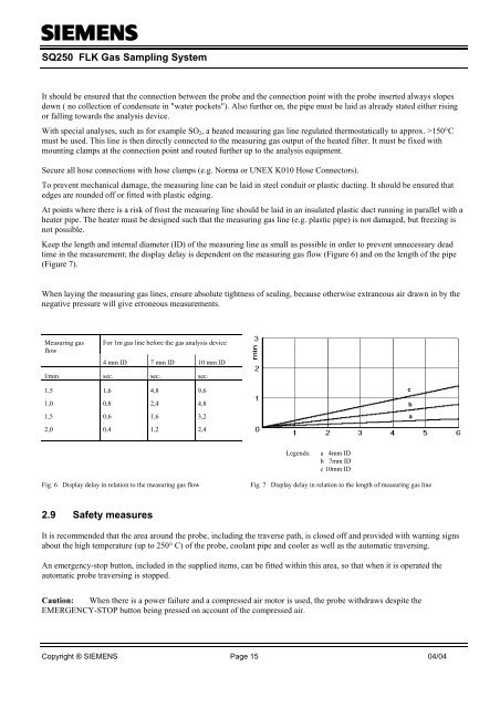
Keep the length and internal diameter (ID) of the measuring line as small as possible in order to prevent unnecessary dead<br />
time in the measurement; the display delay is dependent on the measuring gas flow (Figure 6) and on the length of the pipe<br />
(Figure 7).<br />
When laying the measuring gas lines, ensure absolute tightness of sealing, because otherwise extraneous air drawn in by the<br />
negative pressure will give erroneous measurements.<br />
Measuring gas<br />
flow<br />
For 1m gas line before the gas analysis device<br />
4 mm ID 7 mm ID 10 mm ID<br />
l/min sec. sec. sec.<br />
1,5<br />
1,6<br />
4,8<br />
9,6<br />
c<br />
1,0<br />
0,8<br />
2,4<br />
4,8<br />
b<br />
1,5<br />
0,6<br />
1,6<br />
3,2<br />
a<br />
2,0<br />
0,4<br />
1,2<br />
2,4<br />
Legends:<br />
a 4mm ID<br />
b 7mm ID<br />
c 10mm ID<br />
Fig. 6 Display delay in relation to the measuring gas flow<br />
Fig. 7 Display delay in relation to the length of measuring gas line<br />
2.9 Safety measures<br />
It is recommended that the area around the probe, including the traverse path, is closed off and provided with warning signs<br />
about the high temperature (up to 250° C) of the probe, coolant pipe and cooler as well as the automatic traversing.<br />
An emergency-stop button, included in the supplied items, can be fitted within this area, so that when it is operated the<br />
automatic probe traversing is stopped.<br />
Caution: When there is a power failure and a compressed air motor is used, the probe withdraws despite the<br />
EMERGENCY-STOP button being pressed on account of the compressed air.<br />
Copyright ® SIEMENS Page 15 04/04
![[ ]](https://img.yumpu.com/53283450/1/184x260/-.jpg?quality=85)