FLK Gas Sampling System - MPIP - Free
FLK Gas Sampling System - MPIP - Free
FLK Gas Sampling System - MPIP - Free
- No tags were found...
Create successful ePaper yourself
Turn your PDF publications into a flip-book with our unique Google optimized e-Paper software.
SQ255 Control Unit<br />
2. Installation<br />
2.1 General information<br />
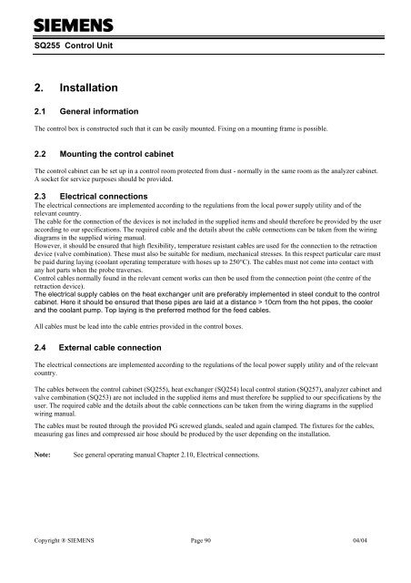
The control box is constructed such that it can be easily mounted. Fixing on a mounting frame is possible.<br />
2.2 Mounting the control cabinet<br />
The control cabinet can be set up in a control room protected from dust - normally in the same room as the analyzer cabinet.<br />
A socket for service purposes should be provided.<br />
2.3 Electrical connections<br />
The electrical connections are implemented according to the regulations from the local power supply utility and of the<br />
relevant country.<br />
The cable for the connection of the devices is not included in the supplied items and should therefore be provided by the user<br />
according to our specifications. The required cable and the details about the cable connections can be taken from the wiring<br />
diagrams in the supplied wiring manual.<br />
However, it should be ensured that high flexibility, temperature resistant cables are used for the connection to the retraction<br />
device (valve combination). These must also be suitable for medium, mechanical stresses. In this respect particular care must<br />
be paid during laying (coolant operating temperature with hoses up to 250°C). The cables must not come into contact with<br />
any hot parts when the probe traverses.<br />
Control cables normally found in the relevant cement works can then be used from the connection point (the centre of the<br />
retraction device).<br />
The electrical supply cables on the heat exchanger unit are preferably implemented in steel conduit to the control<br />
cabinet. Here it should be ensured that these pipes are laid at a distance > 10cm from the hot pipes, the cooler<br />
and the coolant pump. Top laying is the preferred method for the feed cables.<br />
All cables must be lead into the cable entries provided in the control boxes.<br />
2.4 External cable connection<br />
The electrical connections are implemented according to the regulations of the local power supply utility and of the relevant<br />
country.<br />
The cables between the control cabinet (SQ255), heat exchanger (SQ254) local control station (SQ257), analyzer cabinet and<br />
valve combination (SQ253) are not included in the supplied items and must therefore be supplied to our specifications by the<br />
user. The required cable and the details about the cable connections can be taken from the wiring diagrams in the supplied<br />
wiring manual.<br />
The cables must be routed through the provided PG screwed glands, sealed and again clamped. The fixtures for the cables,<br />
measuring gas lines and compressed air hose should be produced by the user depending on the installation.<br />
Note:<br />
See general operating manual Chapter 2.10, Electrical connections.<br />
Copyright ® SIEMENS Page 90 04/04


![[ ]](https://img.yumpu.com/53283450/1/184x260/-.jpg?quality=85)
