FLK Gas Sampling System - MPIP - Free
FLK Gas Sampling System - MPIP - Free
FLK Gas Sampling System - MPIP - Free
- No tags were found...

Create successful ePaper yourself
Turn your PDF publications into a flip-book with our unique Google optimized e-Paper software.
SQ250 <strong>FLK</strong> <strong>Gas</strong> <strong>Sampling</strong> <strong>System</strong><br />
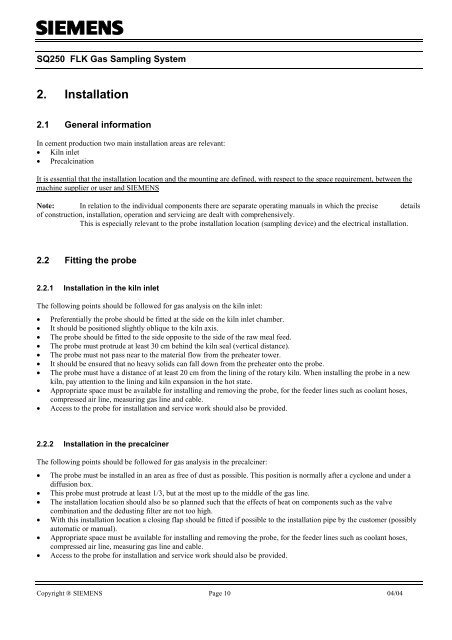
2. Installation<br />
2.1 General information<br />
In cement production two main installation areas are relevant:<br />
• Kiln inlet<br />
• Precalcination<br />
It is essential that the installation location and the mounting are defined, with respect to the space requirement, between the<br />
machine supplier or user and SIEMENS<br />
Note: In relation to the individual components there are separate operating manuals in which the precise details<br />
of construction, installation, operation and servicing are dealt with comprehensively.<br />
This is especially relevant to the probe installation location (sampling device) and the electrical installation.<br />
2.2 Fitting the probe<br />
2.2.1 Installation in the kiln inlet<br />
The following points should be followed for gas analysis on the kiln inlet:<br />
• Preferentially the probe should be fitted at the side on the kiln inlet chamber.<br />
• It should be positioned slightly oblique to the kiln axis.<br />
• The probe should be fitted to the side opposite to the side of the raw meal feed.<br />
• The probe must protrude at least 30 cm behind the kiln seal (vertical distance).<br />
• The probe must not pass near to the material flow from the preheater tower.<br />
• It should be ensured that no heavy solids can fall down from the preheater onto the probe.<br />
• The probe must have a distance of at least 20 cm from the lining of the rotary kiln. When installing the probe in a new<br />
kiln, pay attention to the lining and kiln expansion in the hot state.<br />
• Appropriate space must be available for installing and removing the probe, for the feeder lines such as coolant hoses,<br />
compressed air line, measuring gas line and cable.<br />
• Access to the probe for installation and service work should also be provided.<br />
2.2.2 Installation in the precalciner<br />
The following points should be followed for gas analysis in the precalciner:<br />
• The probe must be installed in an area as free of dust as possible. This position is normally after a cyclone and under a<br />
diffusion box.<br />
• This probe must protrude at least 1/3, but at the most up to the middle of the gas line.<br />
• The installation location should also be so planned such that the effects of heat on components such as the valve<br />
combination and the dedusting filter are not too high.<br />
• With this installation location a closing flap should be fitted if possible to the installation pipe by the customer (possibly<br />
automatic or manual).<br />
• Appropriate space must be available for installing and removing the probe, for the feeder lines such as coolant hoses,<br />
compressed air line, measuring gas line and cable.<br />
• Access to the probe for installation and service work should also be provided.<br />
Copyright ® SIEMENS Page 10 04/04
![[ ]](https://img.yumpu.com/53283450/1/184x260/-.jpg?quality=85)