FLK Gas Sampling System - MPIP - Free
FLK Gas Sampling System - MPIP - Free
FLK Gas Sampling System - MPIP - Free
- No tags were found...

Create successful ePaper yourself
Turn your PDF publications into a flip-book with our unique Google optimized e-Paper software.
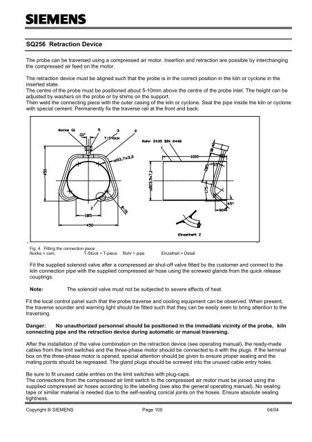
SQ256 Retraction Device<br />
The probe can be traversed using a compressed air motor. Insertion and retraction are possible by interchanging<br />
the compressed air feed on the motor.<br />
The retraction device must be aligned such that the probe is in the correct position in the kiln or cyclone in the<br />
inserted state.<br />
The centre of the probe must be positioned about 5-10mm above the centre of the probe inlet. The height can be<br />
adjusted by washers on the probe or by shims on the support.<br />
Then weld the connecting piece with the outer casing of the kiln or cyclone. Seal the pipe inside the kiln or cyclone<br />
with special cement. Permanently fix the traverse rail at the front and back.<br />
Fig. 4 Fitting the connection piece<br />
Nocke = cam, T-Stück = T-piece Rohr = pipe Einzelheit = Detail<br />
Fit the supplied solenoid valve after a compressed air shut-off valve fitted by the customer and connect to the<br />
kiln connection pipe with the supplied compressed air hose using the screwed glands from the quick release<br />
couplings.<br />
Note:<br />
The solenoid valve must not be subjected to severe effects of heat.<br />
Fit the local control panel such that the probe traverse and cooling equipment can be observed. When present,<br />
the traverse sounder and warning light should be fitted such that they can be easily seen to bring attention to the<br />
traversing.<br />
Danger: No unauthorized personnel should be positioned in the immediate vicinity of the probe, kiln<br />
connecting pipe and the retraction device during automatic or manual traversing.<br />
After the installation of the valve combination on the retraction device (see operating manual), the ready-made<br />
cables from the limit switches and the three-phase motor should be connected to it with the plugs. If the terminal<br />
box on the three-phase motor is opened, special attention should be given to ensure proper sealing and the<br />
mating points should be regreased. The gland plugs should be screwed into the unused cable entry holes.<br />
Be sure to fit unused cable entries on the limit switches with plug-caps.<br />
The connections from the compressed air limit switch to the compressed air motor must be joined using the<br />
supplied compressed air hoses according to the labelling (see also the general operating manual). No sealing<br />
tape or similar material is needed due to the self-sealing conical joints on the hoses. Ensure absolute sealing<br />
tightness.<br />
Copyright ® SIEMENS Page 100 04/04
![[ ]](https://img.yumpu.com/53283450/1/184x260/-.jpg?quality=85)