FLK Gas Sampling System - MPIP - Free
FLK Gas Sampling System - MPIP - Free
FLK Gas Sampling System - MPIP - Free
- No tags were found...

You also want an ePaper? Increase the reach of your titles
YUMPU automatically turns print PDFs into web optimized ePapers that Google loves.
SQ253 Valve Combination<br />
2.2.2 Cable connection to the withdrawal device<br />
The electrical connection from the withdrawal device and the electrically heated filter are implemented in ready-made cable<br />
to the terminal strip in the valve combination (Figure 2, Item 14). The connections are:<br />
• electrically heated filter<br />
• limit switch, Probe Withdrawn<br />
• limit switch, Probe Inserted<br />
• Drive motor for withdrawal device<br />
2.3 Compressed air/measuring gas connection/ ext. cable connection<br />
A quick-release coupling to DIN 3483 is provided for the compressed air connection (Figure 2, Item 1). The NW20<br />
compressed air line must be connected to this.<br />
The measuring gas connection (Figure 2, Item 18) is made via the ready-made, 3.5m long PTFE pressure hose with metal<br />
braiding. This is directly screwed to the angular screwed joint. No further sealing with TEFLON is needed due to the conical<br />
nipple connection on the hose.<br />
The electrical connections are implemented according to the regulations of the local power supply utility and of the relevant<br />
country.<br />
The cables between the valve combination and the controller are not included in the supplied items and must therefore be<br />
supplied to our specifications by the user. The required cable and the details about the cable connections can be taken from<br />
the wiring diagrams in the supplied wiring manual.<br />
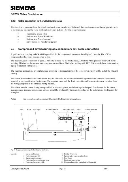
The cables must be routed through the provided M screwed glands, sealed and again clamped. The fixtures for the cables,<br />
measuring gas lines and compressed air hose should be produced by the user depending on the installation. See Figure 3 for<br />
examples.<br />
Note:<br />
See general operating manual Chapter 2.10, Electrical connections.<br />
< 1 > < 2 > < 3 > < 4 > < 8 > < 8 > < 9 ><br />
< 6 ><br />
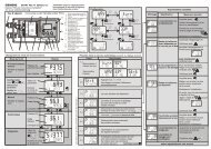
Fig. 3 Suggested fastenings for holding the feed lines.<br />
Legends: 1 Valve combination 6 Flat bar 30 x 4 mm<br />
2 Fastening screw M8 7 Fastening for compressed air hose<br />
3 Cable retention bracket 8 Pipe clamp<br />
4 Fastening for measuring gas hose 9 Plastic cable protection<br />
5 Fastening for control cable 10 M screwed gland for control cable ( Underside )<br />
Copyright ® SIEMENS Page 65 04/04
![[ ]](https://img.yumpu.com/53283450/1/184x260/-.jpg?quality=85)