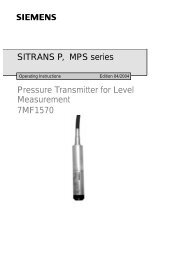
FLK Gas Sampling System - MPIP - Free
FLK Gas Sampling System - MPIP - Free
FLK Gas Sampling System - MPIP - Free
- No tags were found...

Create successful ePaper yourself
Turn your PDF publications into a flip-book with our unique Google optimized e-Paper software.
Siemens<br />
SQ253 Valve Combination<br />
1.3 Field of application<br />
The valve combination is used for the automatic cleaning of <strong>FLK</strong> <strong>Gas</strong> <strong>Sampling</strong> Probes which are mainly used for measuring<br />
gas sampling up to approx. 1800 °C with a high dust content.<br />
Due to the high dust concentration in the process gas, dust deposits in the sampling probe and in the heated filter are<br />
unavoidable. Therefore, automatic, cyclical cleaning has been implemented for the probe and the filter. The mechanical parts<br />
required for this are accommodated in the valve combination. If a compressed air motor is being used for the "emergency<br />
withdrawal" of the probe, the control valves needed for the motor are also in the valve combination.<br />
Note:<br />
See also the general operating manual for the <strong>FLK</strong> Probe.<br />
1.4 Construction<br />
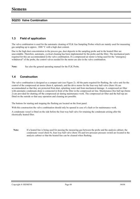
The valve combination is designed as a compact unit (see Figure 2). All the parts required for flushing, the valve unit for the<br />
control of the compressed air motor (Item 4, optional), and the drive motor for the four-way ball valve (Item 10) are<br />
accommodated so that they are protected from dust, splashing water and from mechanical damage. A compressed air filter<br />
with automatic condensate drain is connected in front of the filter in the compressed air line. Maintenance-free ball tap (Items<br />
2) are provided for shutting off the compressed air during maintenance work. The compressed air filter and the ball tap are<br />
fitted on the outside so that easy operation and cleaning are possible.<br />
The buttons for starting and stopping the flushing are located on the front panel.<br />
With this construction the valve combination should only be opened in case of a fault or for maintenance work.<br />
A condensate vessel is fitted on the side before the four-way ball valve for retaining the condensate arising after the<br />
electrically heated filter.<br />
Note:<br />
If a heated line is being used for passing the measuring gas between the probe and the analysis cabinet, the<br />
condensate vessel (Item 9), four-way ball valve (Item 10) and low-pressure pressure switch are located in the<br />
analysis cabinet so that the heated line can be cleaned when flushing.<br />
Copyright ® SIEMENS Page 60 04/04
![[ ]](https://img.yumpu.com/53283450/1/184x260/-.jpg?quality=85)