FLK Gas Sampling System - MPIP - Free
FLK Gas Sampling System - MPIP - Free
FLK Gas Sampling System - MPIP - Free
- No tags were found...

Create successful ePaper yourself
Turn your PDF publications into a flip-book with our unique Google optimized e-Paper software.
SQ250 <strong>FLK</strong> <strong>Gas</strong> <strong>Sampling</strong> <strong>System</strong><br />
2.7 Compressed air connection<br />
The connection point for the compressed air line should be positioned at the same height as the venting containers, but on the<br />
opposite side of the probe. The compressed air line NW20 (length 3.5m) with DIN 3483 hose couplings at both ends must be<br />
used for the connection from this supply point to the valve combination. At the supply point the compressed air should<br />
preferentially be implemented by the customer in 1/2" pipe. A threaded coupling R 1/2" with metal seal as counter piece to<br />
the hose coupling is supplied for the transition to this feed line.<br />
2.8 Measuring gas connection<br />
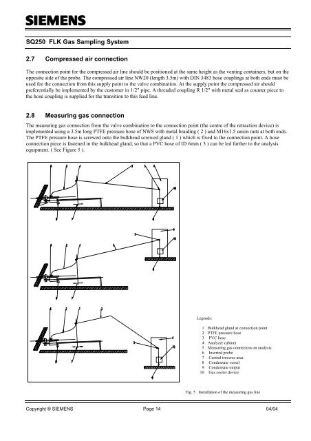
The measuring gas connection from the valve combination to the connection point (the centre of the retraction device) is<br />
implemented using a 3.5m long PTFE pressure hose of NW8 with metal braiding ( 2 ) and M16x1.5 union nuts at both ends.<br />
The PTFE pressure hose is screwed onto the bulkhead screwed gland ( 1 ) which is fixed to the connection point. A hose<br />
connection piece is fastened in the bulkhead gland, so that a PVC hose of ID 6mm ( 3 ) can be led further to the analysis<br />
equipment. ( See Figure 5 ).<br />
Legends:<br />
1 Bulkhead gland at connection point<br />
2 PTFE pressure hose<br />
3 PVC hose<br />
4 Analyzer cabinet<br />
5 Measuring gas connection on analysis<br />
6 Inserted probe<br />
7 Central traverse area<br />
8 Condensate vessel<br />
9 Condensate output<br />
10 <strong>Gas</strong> cooler device<br />
Fig. 5 Installation of the measuring gas line<br />
Copyright ® SIEMENS Page 14 04/04
![[ ]](https://img.yumpu.com/53283450/1/184x260/-.jpg?quality=85)