News letter Dam edition
News letter Dam edition
News letter Dam edition
- No tags were found...

Create successful ePaper yourself
Turn your PDF publications into a flip-book with our unique Google optimized e-Paper software.
Ingeokring <strong>News</strong><strong>letter</strong><br />
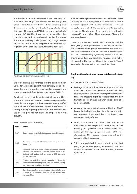
The analysis of the results revealed that the piped soils had<br />
more than 50% of granular particles and the transported<br />
particles consisted mainly of fine and medium sand (Figure<br />
5). Moreover, we could verify that for the piped soils with a<br />
low value of hydraulic load (ΔH=3-6 m) and a low hydraulic<br />
gradient (i=0.06-0.13) piping can occur; provided that<br />
granular layers are laying underneath the dam foundation.<br />
The presence of fine particles (0.2-2.0 mm) in large amounts<br />
can also be an indicator for the possible occurrence of piping<br />
based on the grain size distribution of the piped soils.<br />
Percentage passing [%]<br />
0.02 0.06<br />
0.2<br />
0.6<br />
2<br />
6<br />
20<br />
60<br />
100<br />
0<br />
90<br />
10<br />
80<br />
20<br />
70<br />
30<br />
60<br />
40<br />
50<br />
50<br />
40<br />
60<br />
30<br />
70<br />
Percentage retained [%]<br />
Also permeable layers beneath the foundations were not cut<br />
up totally. In case B piping took place at low water level in<br />
the reservoir (about 5 m below the normal water level). Also<br />
we could observe clearly the tunnels created by the piping<br />
mechanism. The diameter of the tunnels observed varied<br />
between 15 cm and 35 cm. Also the presence of flow of fine<br />
sand was observed.<br />
Besides the above mentioned aspects, it can be said that<br />
some geological and geotechnical conditions contributed to<br />
the occurrence of the piping phenomenon too: dam location<br />
(axis) in meander zones and location of concrete structures<br />
on permeable sandy layers laying parallel to the underground<br />
water flow. Also preventive measures were not totally<br />
completed before the filling of the reservoir. Table 3<br />
summarises the main factors that caused soil piping.<br />
20<br />
10<br />
80<br />
90<br />
0<br />
100<br />
0.01 0.1 1 10 100<br />
Particle size [mm]<br />
Fig. 5 Grain size distribution range of piped soils.<br />
We could observe that for these soils the assumed design<br />
values for admissible gradient were generally ranging between<br />
0.20 and 0.40 and they were based on experience and<br />
scarce data available from literature at that time (Table 2).<br />
Despite of the fact that the designers took into consideration<br />
some preventive measures to reduce seepage underneath<br />
the dams, in practice these measures were not effective<br />
at all. Some of them were incomplete or inefficient, resulting<br />
in locally high seepage through the foundation. The<br />
use of sheet piles did not avoid high seepage, as it was<br />
thought.<br />
Table 3 Main factors that caused piping.<br />
<strong>Dam</strong>s Factors<br />
Case A Sandy layer cut by steel pile, but laying on fissured limestone<br />
Considerations about some measures taken against piping<br />
The main considerations are as follows:<br />
• Drainage structure with an inverted filter acts as pore<br />
water pressure dissipater. However, it does not avoid<br />
seepage, which is considered high in permeable foundations.<br />
This measure might be feasible when the dam<br />
foundation is less granular and when the soil permeability<br />
is not too high.<br />
• An apron or a partial cut-off (or a combination of both)<br />
lowers the hydraulic gradient since the water running<br />
path is enlarged. It was found that in practice this measure<br />
was not totally effective.<br />
• Grout curtains made from cement and bentonite are<br />
effective when the soil porosity allows it, but requires<br />
finishing 3 to 4 profiles before the reservoir is filled up,<br />
avoiding in this way seepage concentration at the middle<br />
stretches. This measure requires time and control<br />
measures while it is executed.<br />
Case B<br />
Case C<br />
Case D<br />
The impervious cut-off did not cut up the sandy layer at affected<br />
zone<br />
Reinforced concrete structure placed (water in-take) on granular<br />
layers, with impervious apron and drainage structure, but<br />
design critical gradient 0.25 compared to 0.13 (the actual<br />
gradient measured)<br />
Grout curtain made from cement in granular foundation, but<br />
reservoir was filled before grout curtain was finished, seepage<br />
was concentrated in affected stretches<br />
• Soil-cement walls built by means of a trench or sheet<br />
piling together with pouring of blended bentonitecement<br />
is considered a safe measure when permeable<br />
layers are cut.<br />
Case E<br />
Deep impervious layer was not cut up with steel piles used.<br />
However, in the zone where bentonite mix was applied, there<br />
was no problem<br />
<strong>Dam</strong> <strong>edition</strong> | Double Issue 2007/2008 | 49