EMPIRE
Flint Hill & Burner VFD(M,R,T) - White Mountain Hearth
Flint Hill & Burner VFD(M,R,T) - White Mountain Hearth

You also want an ePaper? Increase the reach of your titles
YUMPU automatically turns print PDFs into web optimized ePapers that Google loves.
GAS SUPPLY<br />
Check all local codes for requirements, especially for the size and<br />
type of gas supply line required.<br />
Pipe Length<br />
0-10 feet<br />
0-3 meters<br />
10-40 feet<br />
4-12 meters<br />
40-100 feet<br />
13-30 meters<br />
100-150 feet<br />
31-46 meters<br />
Recommended Gas Pipe Diameter<br />
Schedule 40 Pipe<br />
Inside Diameter<br />
Tubing, Type L<br />
Outside Diameter<br />
Nat. L.P. Nat. L.P.<br />
1/2”<br />
12.7mm<br />
1/2”<br />
12.7mm<br />
1/2”<br />
12.7mm<br />
3/4”<br />
19mm<br />
3/8”<br />
9.5mm<br />
1/2”<br />
12.7mm<br />
1/2”<br />
12.7mm<br />
1/2”<br />
12.7mm<br />
1/2”<br />
12.7mm<br />
5/8”<br />
15.9mm<br />
3/4”<br />
19mm<br />
7/8”<br />
22.2mm<br />
3/8”<br />
9.5mm<br />
1/2”<br />
12.7mm<br />
1/2”<br />
12.7mm<br />
3/4”<br />
19mm<br />
NOTICE: Never use plastic pipe. Check to confirm whether your<br />
local codes allow copper tubing or galvanized.<br />
NOTICE: Since some municipalities have additional local codes, it is<br />
always best to consult your local authority and installation code.<br />
Installing a New Main Gas Cock<br />
Each appliance should have its own manual gas cock.<br />
A manual main gas cock should be located in the vicinity of the unit.<br />
Where none exists, or where its size or location is not adequate,<br />
contact your local authorized installer for installation or relocation.<br />
Compounds used on threaded joints of gas piping shall be resistant<br />
to the action of liquefied petroleum gases. The gas lines must be<br />
checked for leaks by the installer. This should be done with a soap<br />
solution watching for bubbles on all exposed connections, and if<br />
unexposed, a pressure test should be made.<br />
Never use an exposed flame to check for leaks. Appliance must<br />
be disconnected from piping at inlet of control valve and pipe<br />
capped or plugged for pressure test. Never pressure test with<br />
appliance connected; control valve will sustain damage!<br />
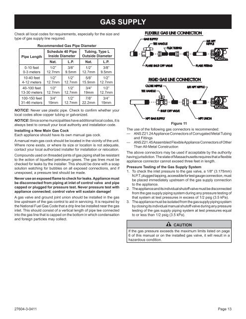
A gas valve and ground joint union should be installed in the gas<br />
line upstream of the gas control to aid in servicing. It is required by<br />
the National Fuel Gas Code that a drip line be installed near the gas<br />
inlet. This should consist of a vertical length of pipe tee connected<br />
into the gas line that is capped on the bottom in which condensation<br />
and foreign particles may collect.<br />
Figure 11<br />
The use of the following gas connectors is recommended:<br />
— ANS Z21.24 Appliance Connectors of Corrugated Metal Tubing<br />
and Fittings<br />
— ANS Z21.45 Assembled Flexible Appliance Connectors of Other<br />
Than All-Metal Construction<br />
The above connectors may be used if acceptable by the authority<br />
having jurisdiction. The state of Massachusetts requires that a flexible<br />
appliance connector cannot exceed three feet in length.<br />
Pressure Testing of the Gas Supply System<br />
1. To check the inlet pressure to the gas valve, a 1/8" (3.175mm)<br />
N.P.T. plugged tapping, accessible for test gauge connection, must<br />
be placed immediately upstream of the gas supply connection<br />
to the appliance.<br />
2. The appliance and its individual shutoff valve must be disconnected<br />
from the gas supply piping system during any pressure testing of<br />
that system at test pressures in excess of 1/2 psig (3.5 kPa).<br />
3. The appliance must be isolated from the gas supply piping system<br />
by closing its individual manual shutoff valve during any pressure<br />
testing of the gas supply piping system at test pressures equal<br />
to or less than 1/2 psig (3.5 kPa).<br />
CAUTION<br />
If the gas pressure exceeds the maximum limits listed on page<br />
6 of this manual or on the installed gas valve, it will result in a<br />
hazardous condition.<br />
27604-3-0411 Page 13