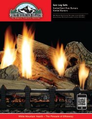
EMPIRE
Flint Hill & Burner VFD(M,R,T) - White Mountain Hearth
Flint Hill & Burner VFD(M,R,T) - White Mountain Hearth

Create successful ePaper yourself
Turn your PDF publications into a flip-book with our unique Google optimized e-Paper software.
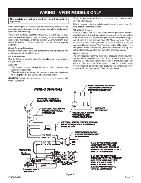
WIRING - VFDR MODELS ONLY<br />
Thermostats are not approved on vented decorative<br />
appliances.<br />
Label all wires prior to disconnection when servicing controls. Wiring<br />
errors can cause improper and dangerous operation. Verify proper<br />
operation after servicing.<br />
18", 24" and 30" Gas Logs (Millivolt) thermopile is self powered gas<br />
valve and does not require 110 volts. See Figure to provide optional<br />
wall switch, thermostat, or remote control. Maximum length of 20<br />
feet of 16 AWG to conductor wires is to be used with all optional<br />
switches.<br />
Check System Operation<br />
Millivolt system and all individual components may be checked with<br />
a millivolt meter 0-1000 MV range.<br />
Remote Receiver<br />
Use the following steps to place the remote receiver adjacent to<br />
the gas valve.<br />
Attention:<br />
1. The remote receiver can not be placed behind the gas valve<br />
and burner assembly.<br />
2. When facing the appliance, the remote receiver must be placed<br />
to the right of the gas valve and burner assembly.<br />
CAUTION: Do not let remote control receiver come in contact with<br />
burner assembly.<br />
On circulating vent-free firebox, install remote control receiver<br />
behind bottom louver.<br />
Refer to remote control installation and operating instructions for<br />
more details on remote control.<br />
750 Millivolt System<br />
When you ignite the pilot, the thermocouple produces millivolts<br />
(electrical current) which energizes the magnet in the gas valve.<br />
After 30 seconds to 1 minute time period you can release the gas<br />
control knob and the pilot will stay ON. Allow your pilot flame to<br />
operate an additional one (1) to two (2) minutes before you turn the<br />
gas control knob from the PILOT position to the ON position. This<br />
time period allows the millivolts (electrical current) to buildup to a<br />
sufficient level allowing the gas control to operate properly.<br />
Millivolt Control<br />
The valve regulator controls the burner pressure which should be<br />
checked at the pressure test point. Turn captured screw counter<br />
clockwise 2 or 3 turns and then place tubing to pressure gauge over<br />
test point (Use test point “A” closest to control knob). After taking<br />
pressure reading, be sure and turn captured screw clockwise firmly<br />
to re-seal. Do not over torque. Check for gas leaks.<br />
WIRING DIAGRAM<br />
H<br />
REMOTE CONTROL RECEIVER/<br />
THERMOSTAT/ CONTROLE E<br />
DISTANCE DU RECEPTEUR<br />
N<br />
(OPTIONAL) THERMOSTAT<br />
(FACULATIVE) THERMOSTAT<br />
(OPTIONAL) WALL SWITCH<br />
INTERRUPTEUR MURAL<br />
(FACULTATIVE)<br />
REMOTE/OFF/ON SWITCH<br />
A DISTANCE/OUVERT/<br />
FERME INTERRUPTEUR<br />
GAS VALVE<br />
VALVEDE GAZ<br />
(OPTIONAL) REMOTE CONTROL RECEIVER<br />
(FACULTATIVE) CONTROLE EDISTANCE<br />
DU RECEPTEUR<br />
THERMOPILE<br />
PILOT<br />
VEILLEUSE<br />
THERMOCOUPLE<br />
(NATURAL)<br />
THERMOCOUPLE<br />
(LPG)<br />
GAS VALVE<br />
REMOTE/OFF/ON SWITCH<br />
A DISTANCE/FERME/OUVERT<br />
INTERRUPTEUR<br />
REMOTE<br />
IF ANY OF THE ORIGINAL WIRE<br />
AS SUPPLIED WITH THIS UNIT<br />
MUST BE REPLACED, IT MUST BE<br />
REPLACED WITH NUMBER 18, 150°C<br />
WIRE OR ITS EQUIVALENT.<br />
SI UN DES FILS ELECTRIQUES<br />
ORIGINAUX, VENANT DU FABRICANT<br />
AVEC CETTE UNITE, DOIT ETRE<br />
REMPLACE, VOUS DEVEZ LE<br />
REMPLACER AVEC UN FIL<br />
ELECTRIQUE DE NUMERO 18,<br />
150 ° CDUL'EQUIVALENT.<br />
Figure 20<br />
27604-3-0411 Page 17<br />
OFF<br />
ON