Chapter 8 Lab B Configuring a Remote Access VPN Server and Client
Chapter 8: Lab B: Configuring a Remote Access VPN Server and ...
Chapter 8: Lab B: Configuring a Remote Access VPN Server and ...
- No tags were found...

Create successful ePaper yourself
Turn your PDF publications into a flip-book with our unique Google optimized e-Paper software.
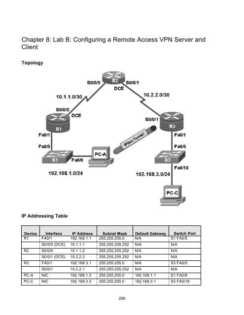
<strong>Chapter</strong> 8: <strong>Lab</strong> B: <strong>Configuring</strong> a <strong>Remote</strong> <strong>Access</strong> <strong>VPN</strong> <strong>Server</strong> <strong>and</strong><br />
<strong>Client</strong><br />
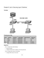
Topology<br />
IP Addressing Table<br />
Device Interface IP Address Subnet Mask Default Gateway Switch Port<br />
R1 FA0/1 192.168.1.1 255.255.255.0 N/A S1 FA0/5<br />
S0/0/0 (DCE) 10.1.1.1 255.255.255.252 N/A N/A<br />
R2 S0/0/0 10.1.1.2 255.255.255.252 N/A N/A<br />
S0/0/1 (DCE) 10.2.2.2 255.255.255.252 N/A N/A<br />
R3 FA0/1 192.168.3.1 255.255.255.0 N/A S3 FA0/5<br />
S0/0/1 10.2.2.1 255.255.255.252 N/A N/A<br />
PC-A NIC 192.168.1.3 255.255.255.0 192.168.1.1 S1 FA0/6<br />
PC-C NIC 192.168.3.3 255.255.255.0 192.168.3.1 S3 FA0/18<br />
206
Objectives<br />
Part 1: Basic Router Configuration<br />
• Configure host names, interface IP addresses, <strong>and</strong> access passwords.<br />
• Configure static routing.<br />
Part 2: <strong>Configuring</strong> a <strong>Remote</strong> <strong>Access</strong> <strong>VPN</strong><br />
• Configure a zone-based firewall (ZBF) on R3 using SDM.<br />
• Configure Router R3 to support Cisco Easy <strong>VPN</strong> <strong>Server</strong> using SDM.<br />
• Configure the Cisco <strong>VPN</strong> <strong>Client</strong> on PC-A <strong>and</strong> connect to R3.<br />
• Verify the configuration.<br />
• Test <strong>VPN</strong> functionality.<br />
Background<br />
<strong>VPN</strong>s can provide a secure method of transmitting data over a public network, such as the Internet. A<br />
common <strong>VPN</strong> implementation is used for remote access to a corporate office from a telecommuter location<br />
such as a small office or home office (SOHO).<br />
In this lab, you build a multi-router network <strong>and</strong> configure the routers <strong>and</strong> hosts. You configure a remote<br />
access IPsec <strong>VPN</strong> between a client computer <strong>and</strong> a simulated corporate network. You start by using SDM to<br />
configure a zoned-based firewall (ZBF) to prevent connections from outside the corporate network. You also<br />
use SDM to configure Cisco Easy <strong>VPN</strong> <strong>Server</strong> on the corporate gateway router. Next, you configure the Cisco<br />
<strong>VPN</strong> <strong>Client</strong> on a host <strong>and</strong> connect to the corporate network through a simulated ISP router.<br />
The Cisco <strong>VPN</strong> <strong>Client</strong> allows organizations to establish end-to-end, encrypted (IPsec) <strong>VPN</strong> tunnels for secure<br />
connectivity for mobile employees or teleworkers. It supports Cisco Easy <strong>VPN</strong>, which allows the client to<br />
receive security policies upon a <strong>VPN</strong> tunnel connection from the central site <strong>VPN</strong> device (Cisco Easy <strong>VPN</strong><br />
<strong>Server</strong>), minimizing configuration requirements at the remote location. Easy <strong>VPN</strong> is a scalable solution for<br />
remote access deployments for which it is impractical to individually configure policies for multiple remote<br />
PCs.<br />
Router R1 represents a remote site, <strong>and</strong> R3 represents the corporate headquarters. Host PC-A simulates an<br />
employee connecting from home or a small office over the Internet. Router R2 simulates an Internet ISP<br />
router <strong>and</strong> acts as a passthrough with no knowledge of the <strong>VPN</strong> connection running through it.<br />
Note: The router comm<strong>and</strong>s <strong>and</strong> output in this lab are from a Cisco 1841 with Cisco IOS Release 12.4(20)T<br />
(Advanced IP image). Other routers <strong>and</strong> Cisco IOS versions can be used. See the Router Interface Summary<br />
table at the end of the lab to determine which interface identifiers to use based on the equipment in the lab.<br />
Depending on the router model <strong>and</strong> Cisco IOS version, the comm<strong>and</strong>s available <strong>and</strong> output produced might<br />
vary from what is shown in this lab.<br />
Note: Make sure that the routers <strong>and</strong> the switches have been erased <strong>and</strong> have no startup configurations.<br />
Required Resources<br />
• 3 routers with Cisco 1841 with Cisco IOS Release 12.4(20)T1 or comparable (2 routers with SDM 2.5<br />
installed)<br />
• 2 switches (Cisco 2960 or comparable)<br />
207
• PC-A - Windows XP or Vista (with Cisco <strong>VPN</strong> <strong>Client</strong>)<br />
• PC-C (Windows XP or Vista)<br />
• Serial <strong>and</strong> Ethernet cables as shown in the topology<br />
• Rollover cables to configure the routers via the console<br />
Part 1. Basic Router Configuration<br />
In Part 1, you set up the network topology <strong>and</strong> configure basic settings, such as the interface IP addresses<br />
<strong>and</strong> static routing. Perform the steps on the routers as indicated.<br />
Step 1: Cable the network as shown in the topology.<br />
Attach the devices shown in the topology diagram, <strong>and</strong> cable as necessary.<br />
Step 2: Configure basic settings for all routers.<br />
a. Configure host names as shown in the topology.<br />
b. Configure the physical interface IP addresses as shown in the IP addressing table.<br />
c. Configure a clock rate for the routers with a DCE serial cable attached to their serial interface.<br />
R1(config)#interface S0/0/0<br />
R1(config-if)#clock rate 64000<br />
d. Disable DNS lookup to prevent the router from attempting to translate incorrectly entered comm<strong>and</strong>s<br />
as though they were host names.<br />
R1(config)#no ip domain-lookup<br />
Step 3: Configure static default routes on R1 <strong>and</strong> R3.<br />
Configure a static default route from R1 to R2 <strong>and</strong> from R3 to R2.<br />
R1(config)#ip route 0.0.0.0 0.0.0.0 10.1.1.2<br />
R3(config)#ip route 0.0.0.0 0.0.0.0 10.2.2.2<br />
Step 4: Configure static routes on R2.<br />
Configure a static route from R2 to the R1 LAN.<br />
R2(config)#ip route 192.168.1.0 255.255.255.0 10.1.1.1<br />
Configure a static route from R2 to the R3 LAN.<br />
R2(config)#ip route 192.168.3.0 255.255.255.0 10.2.2.1<br />
Step 5: Configure PC host IP settings.<br />
Configure a static IP address, subnet mask, <strong>and</strong> default gateway for PC-A <strong>and</strong> PC-C, as shown in the IP<br />
addressing table.<br />
208
Step 6: Verify connectivity between PC-A <strong>and</strong> R3.<br />
From PC-A, ping the R3 S0/0/1 interface at IP address 10.2.2.1.<br />
PC-A:\>ping 10.2.2.1<br />
Are the results successful? _____<br />
If the pings are not successful, troubleshoot the basic device configurations before continuing.<br />
Step 7: Configure a minimum password length.<br />
Note: Passwords in this lab are set to a minimum of 10 characters, but are relatively simple for the benefit<br />
of performing the lab. More complex passwords are recommended in a production network.<br />
Use the security passwords comm<strong>and</strong> to set a minimum password length of 10 characters.<br />
R1(config)#security passwords min-length 10<br />
Step 8: Configure the enable secret password <strong>and</strong> console <strong>and</strong> vty lines.<br />
a. Configure the enable secret password cisco12345 on R1.<br />
R1(config)#enable secret cisco12345<br />
b. Configure a console password <strong>and</strong> enable login for router R1. For additional security, the exectimeout<br />
comm<strong>and</strong> causes the line to log out after 5 minutes of inactivity. The logging synchronous<br />
comm<strong>and</strong> prevents console messages from interrupting comm<strong>and</strong> entry.<br />
Note: To avoid repetitive logins during this lab, the exec-timeout can be set to 0 0, which prevents<br />
it from expiring. However, this is not considered a good security practice.<br />
R1(config)#line console 0<br />
R1(config-line)#password ciscoconpass<br />
R1(config-line)#exec-timeout 5 0<br />
R1(config-line)#login<br />
R1(config-line)#logging synchronous<br />
c. Configure the password on the vty lines for router R1.<br />
R1(config)#line vty 0 4<br />
R1(config-line)#password ciscovtypass<br />
R1(config-line)#exec-timeout 5 0<br />
R1(config-line)#login<br />
d. Repeat these configurations on R2 <strong>and</strong> R3.<br />
Step 9: Encrypt clear text passwords.<br />
a. Use the service password-encryption comm<strong>and</strong> to encrypt the console, aux, <strong>and</strong> vty passwords.<br />
R1(config)#service password-encryption<br />
b. Issue the show run comm<strong>and</strong>. Can you read the console, aux, <strong>and</strong> vty passwords? Why or why not?<br />
___________________________________________<br />
c. Repeat this configuration on R2 <strong>and</strong> R3.<br />
209
Step 10: Configure a login warning banner on routers R1 <strong>and</strong> R3.<br />
Configure a warning to unauthorized users with a message-of-the-day (MOTD) banner.<br />
R1(config)#banner motd $Unauthorized access strictly prohibited <strong>and</strong><br />
prosecuted to the full extent of the law$<br />
Step 11: Save the basic running configuration for all three routers.<br />
Save the running configuration to the startup configuration from the privileged EXEC prompt.<br />
R1#copy running-config startup-config<br />
Part 2. <strong>Configuring</strong> a <strong>Remote</strong> <strong>Access</strong> <strong>VPN</strong><br />
In Part 2 of this lab, you configure a firewall <strong>and</strong> a remote access IPsec <strong>VPN</strong>. R3 is configured as a <strong>VPN</strong><br />
server using SDM, <strong>and</strong> PC-A is configured as a Cisco <strong>VPN</strong> <strong>Client</strong>.<br />
Task 1. Prepare R3 for SDM <strong>Access</strong><br />
Step 1: Configure HTTP router access <strong>and</strong> a AAA user prior to starting SDM.<br />
a. Enable the HTTP server on R3.<br />
R3(config)#ip http server<br />
Note: For added security, you can enable the HTTP secure server on R3 using the ip http secureserver<br />
comm<strong>and</strong>. The HTTP server <strong>and</strong> the HTTP secure server are disabled by default.<br />
b. Create an admin01 account on R3 with privilege level 15 <strong>and</strong> a password of admin01pass for use with<br />
AAA.<br />
R3(config)#username admin01 privilege 15 password 0 admin01pass<br />
Step 2: <strong>Access</strong> SDM <strong>and</strong> set comm<strong>and</strong> delivery preferences.<br />
a. Run the SDM application or open a browser on PC-C. Start SDM by entering the R3 Fa0/1 IP address<br />
192.168.3.1 in the address field.<br />
b. Log in with no username <strong>and</strong> the enable secret password cisco12345.<br />
c. In the Authentication Required dialog box, enter cisco12345 in the Password field <strong>and</strong> click OK.<br />
d. If the IOS IPS Login dialog box appears, enter the enable secret password cisco12345.<br />
e. Select Edit > Preferences to allow you to preview the comm<strong>and</strong>s before sending them to the router. In the<br />
User Preferences window, check the Preview comm<strong>and</strong>s before delivering to router check box <strong>and</strong> click<br />
OK.<br />
Task 2. Configure a ZBF Firewall on R3<br />
Step 1: Use the SDM Firewall Wizard to configure a zone-based firewall (ZBF) on R3.<br />
a. Click the Configure button at the top of the SDM screen, <strong>and</strong> then click Firewall <strong>and</strong> ACL.<br />
210
. Select Basic Firewall <strong>and</strong> click the Launch the selected task button. On the Basic Firewall<br />
Configuration wizard screen, click Next.<br />
c. Check the Inside (trusted) check box for FastEthernet0/1 <strong>and</strong> the Outside (untrusted) check box for<br />
Serial0/0/1. Click Next. Click OK when the SDM launch warning for Serial0/0/1 is displayed.<br />
211
d. In the next window, select Low Security for the security level <strong>and</strong> click Next.<br />
e. In the Summary window, click Finish.<br />
f. Click Deliver to send the comm<strong>and</strong>s to the router. Click OK in the Comm<strong>and</strong>s Delivery Status window.<br />
Click OK on the Information window. You are returned to the Edit Firewall Policy tab as follows.<br />
Step 2: Verify firewall functionality.<br />
a. From PC-C, ping the R2 interface S0/0/1 at IP address 10.2.2.2.<br />
Are the pings successful? Why or why not?<br />
_______________________________________________________________________________<br />
b. From external router R2, ping PC-C at IP address 192.168.3.3<br />
Are the pings successful? Why or why not?<br />
_______________________________________________________________________________<br />
212
Task 3. Use the SDM <strong>VPN</strong> Wizard to Configure the Easy <strong>VPN</strong> <strong>Server</strong><br />
Step 1: Launch the Easy <strong>VPN</strong> <strong>Server</strong> wizard <strong>and</strong> configure AAA services.<br />
a. Click the Configure button at the top of the SDM home screen. Click the <strong>VPN</strong> task button to view the<br />
<strong>VPN</strong> configuration page.<br />
b. Select Easy <strong>VPN</strong> <strong>Server</strong> from the main <strong>VPN</strong> window, <strong>and</strong> then click Launch Easy <strong>VPN</strong> <strong>Server</strong><br />
Wizard.<br />
c. The Easy <strong>VPN</strong> <strong>Server</strong> wizard checks the router configuration to see if AAA is enabled. If AAA is not<br />
enabled, the Enable AAA window displays. AAA must be enabled on the router before the Easy <strong>VPN</strong><br />
<strong>Server</strong> configuration starts. Click Yes to continue with the configuration.<br />
d. When prompted to deliver the configuration to the router, click Deliver.<br />
e. In the Comm<strong>and</strong> Delivery Status window, click OK. When the message “AAA has been successfully<br />
enabled on the router” displays, click OK.<br />
f. When returned to the Easy <strong>VPN</strong> <strong>Server</strong> wizard window, click Next.<br />
213
g. Now that AAA is enabled, you can start the Easy <strong>VPN</strong> <strong>Server</strong> wizard by clicking the Launch Easy <strong>VPN</strong><br />
<strong>Server</strong> Wizard button. Read through the descriptions of the tasks that the wizard guides you through.<br />
How does the client receive the IPsec policies? ___________________________________________<br />
How does the Easy <strong>VPN</strong> remote server configuration differ from the site-to-site?<br />
____________________________________________________________________________________<br />
____________________________________________________________________________________<br />
h. Click Next when you are finished answering the above questions.<br />
Step 2: Configure the virtual tunnel interface <strong>and</strong> authentication.<br />
a. Select the interface on which the client connections terminate. Click the Unnumbered to radio button<br />
<strong>and</strong> select the Serial0/0/1 interface from the pull-down menu.<br />
b. Select Pre-shared Keys for the authentication type <strong>and</strong> click Next to continue.<br />
214
215
Step 3: Select an IKE proposal.<br />
a. In the IKE Proposals window, the default IKE proposal is used for R3.<br />
What is the encryption method used with the default IKE policy? ____________<br />
What is the hash algorithm used to ensure that the keys have not been tampered with? _____________<br />
b. Click Next to accept the default IKE policy.<br />
Note: Configurations on both sides of the tunnel must match exactly. The Cisco <strong>VPN</strong> <strong>Client</strong> automatically<br />
selects the proper configuration for itself. Therefore, an IKE configuration is not necessary on the client<br />
PC.<br />
216
Step 4: Select the transform set.<br />
a. In the Transform Set window, the default SDM transform set is used. What ESP encryption method is<br />
used with the default transform set? _________________<br />
b. Click Next to accept the default transform set.<br />
217
Step 5: Specify group authorization <strong>and</strong> group policy lookup.<br />
a. In the Group Authorization <strong>and</strong> Group Policy Lookup window, select the Local option.<br />
b. Click Next to create a new AAA method list for group policy lookup that uses the local router database.<br />
218
Step 6: Configure user authentication (XAuth).<br />
a. In the User Authentication (Xauth) window, you can specify to store user information on an external<br />
server, such as a RADIUS server or a local database, or both. Select the Enable User<br />
Authentication check box <strong>and</strong> accept the default of Local Only.<br />
Where does the router look for valid user accounts <strong>and</strong> passwords to authenticate remote <strong>VPN</strong> users<br />
when they attempt to log in?<br />
________________________________________________________________________________<br />
b. Click the Add User Credentials button. In the User Accounts window, you can view currently defined<br />
users or add new users.<br />
What is the name of the user currently defined <strong>and</strong> what is the user privilege level? ______________<br />
How was this user defined? __________________________________________________________<br />
219
c. In the User Accounts window, click the Add button to add another user. Enter the username <strong>VPN</strong>user1<br />
with a password of <strong>VPN</strong>user1pass. Select the check box for encrypting the password using the MD5<br />
hash algorithm. Leave the privilege level at 1.<br />
What is the range of privilege level that can be set for a user? _________________________<br />
d. Click OK to accept the <strong>VPN</strong>user1 entries, <strong>and</strong> then click OK to close the User Accounts window.<br />
e. In the User Authentication (XAuth) window, click Next to continue.<br />
220
Step 7: Specify group authorization <strong>and</strong> user group policies.<br />
In the Group Authorization <strong>and</strong> User Group Policies window, you must create at least one group policy for<br />
the <strong>VPN</strong> server.<br />
a. Click Add to create a group policy.<br />
b. In the Add Group Policy window, enter <strong>VPN</strong>-<strong>Access</strong> as the name of this group. Enter a new preshared<br />
key of cisco12345 <strong>and</strong> then re-enter it.<br />
c. Leave the Pool Information box checked <strong>and</strong> enter a starting address of 192.168.3.100, an ending<br />
address of 192.168.3.150, <strong>and</strong> a subnet mask of 255.255.255.0.<br />
d. Enter 50 for the Maximum Connections Allowed.<br />
e. Click OK to accept the entries.<br />
221
f. An SDM warning message displays indicating that the IP addresses in the pool <strong>and</strong> the IP address of<br />
the FastEthernet0/1 interface are in the same subnet. Click Yes to continue.<br />
g. When you return to the Group Authorization window, check the Configure Idle Timer check box <strong>and</strong><br />
enter one hour (1). This disconnects idle users if there is no activity for one hour <strong>and</strong> allows others to<br />
connect. Click Next to continue.<br />
222
h. When the Cisco Tunneling Control Protocol (cTCP) window displays, do not enable cTCP. Click Next<br />
to continue.<br />
i. When the Easy <strong>VPN</strong> <strong>Server</strong> Passthrough Configuration window displays, make sure that the Action<br />
Modify check box is checked. This option allows SDM to modify the firewall on S0/0/1 to allow IPsec <strong>VPN</strong><br />
traffic to reach the internal LAN. Click OK to continue.<br />
223
Step 8: Review the configuration summary <strong>and</strong> deliver the comm<strong>and</strong>s.<br />
a. Scroll through the comm<strong>and</strong>s that SDM will send to the router. Do not check the check box to test the<br />
<strong>VPN</strong>. Click Finish.<br />
b. When prompted to deliver the configuration to the router, click Deliver.<br />
c. In the Comm<strong>and</strong> Delivery Status window, click OK. How many comm<strong>and</strong>s are delivered? _________<br />
224
Step 9: Test the <strong>VPN</strong> <strong>Server</strong>.<br />
a. You are returned to the main <strong>VPN</strong> window with the Edit Easy <strong>VPN</strong> <strong>Server</strong> tab selected. Click the Test<br />
<strong>VPN</strong> <strong>Server</strong> button in the lower right corner of the screen.<br />
b. In the <strong>VPN</strong> Troubleshooting window, click the Start button.<br />
c. Your screen should look similar to the one below. Click OK to close the information window. Click<br />
Close to exit the <strong>VPN</strong> Troubleshooting window.<br />
225
Task 4. Use the Cisco <strong>VPN</strong> <strong>Client</strong> to Test the <strong>Remote</strong> <strong>Access</strong> <strong>VPN</strong><br />
Step 1: (Optional) Install the Cisco <strong>VPN</strong> client.<br />
If the Cisco <strong>VPN</strong> <strong>Client</strong> software on host PC-A is not installed, install it now. If you do not have the Cisco <strong>VPN</strong><br />
<strong>Client</strong> software, contact your instructor.<br />
Step 2: Configure PC-A as a <strong>VPN</strong> client to access the R1 <strong>VPN</strong> server.<br />
a. Start the Cisco <strong>VPN</strong> <strong>Client</strong> <strong>and</strong> select Connection Entries > New, or click the New icon with the red<br />
plus sign (+) on it.<br />
b. Enter the following information to define the new connection entry. Click Save when you are finished.<br />
226
Connection Entry: <strong>VPN</strong>-R3<br />
Description: Connection to R3 internal network<br />
Host: 10.2.2.1 (IP address of the R3 S0/0/1 interface)<br />
Group Authentication Name: <strong>VPN</strong>-<strong>Access</strong> (defines the address pool configured in Task 2)<br />
Password: cisco12345 (pre-shared key configured in Task 2)<br />
Confirm Password: cisco12345<br />
Note: The group authentication name <strong>and</strong> password are case-sensitive <strong>and</strong> must match the ones created<br />
on the <strong>VPN</strong> <strong>Server</strong>.<br />
Step 3: Test access from PC-A without a <strong>VPN</strong> connection.<br />
In the previous step, you created a <strong>VPN</strong> connection entry on the <strong>VPN</strong> client computer PC-A but have not<br />
activated it, so the <strong>VPN</strong> tunnel is not yet up.<br />
Open a comm<strong>and</strong> prompt on PC-A <strong>and</strong> ping the PC-C IP address at 192.168.3.3 on the R3 LAN. Are the<br />
pings successful? Why or why not?<br />
____________________________________________________________________________________<br />
____________________________________________________________________________________<br />
Step 4: Establish a <strong>VPN</strong> connection <strong>and</strong> log in.<br />
a. Select the newly created connection <strong>VPN</strong>-R3 <strong>and</strong> click the Connect icon. You can also double-click<br />
the connection entry.<br />
227
. Enter the previously created username <strong>VPN</strong>user1 in the <strong>VPN</strong> <strong>Client</strong> User Authentication dialog box<br />
<strong>and</strong> enter the password <strong>VPN</strong>user1pass. Click OK to continue. The <strong>VPN</strong> <strong>Client</strong> window minimizes to a<br />
lock icon in the tools tray of the taskbar. When the lock is closed, the <strong>VPN</strong> tunnel is up. When it is open,<br />
the <strong>VPN</strong> connection is down.<br />
Task 5. Verify the <strong>VPN</strong> Tunnel Between the <strong>Client</strong>, <strong>Server</strong>, <strong>and</strong> Internal Network<br />
Step 1: Open the <strong>VPN</strong> <strong>Client</strong> icon.<br />
a. Double-click the <strong>VPN</strong> lock icon to exp<strong>and</strong> the <strong>VPN</strong> <strong>Client</strong> window.<br />
What does it say about the connection status at the top of the window? ________________________<br />
b. From the PC-A comm<strong>and</strong> line, issue the ipconfig comm<strong>and</strong>.<br />
What is the IP address of the first Local Area Connection? __________________________________<br />
What is the IP address of Local Area Connection 2? _______________________________________<br />
Step 2: Close the <strong>VPN</strong> connection <strong>and</strong> reopen it.<br />
a. Click the Disconnect icon in the <strong>VPN</strong> <strong>Client</strong> window to close the <strong>VPN</strong>-R3 connection.<br />
b. Click the Connect icon <strong>and</strong> log in again as <strong>VPN</strong>user1.<br />
228
What is the IP address of Local Area Connection 2 now? __________________________<br />
Note: Each time you disconnect <strong>and</strong> reconnect to the <strong>VPN</strong> server, you receive a new IP address until the<br />
limit is reached.<br />
Step 3: Check the tunnel statistics.<br />
a. Select Status > Statistics. Click the Tunnel Details tab.<br />
b. What is the current address obtained from the R3 <strong>VPN</strong> server <strong>and</strong> what is the range of addresses that<br />
can be assigned?<br />
______________________________________________________________________________<br />
What is the <strong>VPN</strong> server address? _____________________<br />
How many packets have been encrypted? ______________<br />
What is the encryption method? ______________________<br />
What is the authentication method? ___________________<br />
c. Leave the <strong>VPN</strong> <strong>Client</strong> Statistics window open.<br />
Step 4: Test access from the client PC-A using the <strong>VPN</strong> connection.<br />
With the <strong>VPN</strong> connection from computer PC-A to router R3 activated, open a comm<strong>and</strong> prompt on PC-A<br />
<strong>and</strong> ping the PC-C IP address at 192.168.3.3 on the R3 LAN. Are the pings successful? Why or why<br />
not? ________________________________________________________________________<br />
How many packets have now been encrypted? __________________________________________<br />
229
Step 5: Check the Cisco IOS message on R3 when the tunnel is created.<br />
Open the console connection for R3 <strong>and</strong> locate the message displayed indicating that the virtual interface<br />
came up when the <strong>VPN</strong> <strong>Client</strong> connection was made.<br />
What is the name of the interface on R3 that is activated for the <strong>VPN</strong>? __________________________<br />
Step 6: Verify the <strong>VPN</strong> connection information for PC-A.<br />
From the PC-A comm<strong>and</strong> prompt, issue the ipconfig /all comm<strong>and</strong> to see the network connections.<br />
a. What is the configuration for the first Local Area Connection?<br />
IP Address: ________________________________________<br />
Subnet Mask: ______________________________________<br />
Default Gateway: ___________________________________<br />
Description: _______________________________________<br />
b. What is the configuration for Local Area Connection 2?<br />
IP Address: ________________________________________<br />
Subnet Mask: ______________________________________<br />
Default Gateway: ___________________________________<br />
Description: ________________________________________<br />
Step 7: Telnet from PC-A to R3.<br />
From the PC-A comm<strong>and</strong> prompt, telnet to R3 at the Fa0/1 IP address 192.168.3.1. Log in as admin01<br />
with a password of admin01pass. What is the router comm<strong>and</strong> prompt <strong>and</strong> why is this?<br />
______________________________________________________________________________<br />
a. Issue the show run comm<strong>and</strong> to view the various comm<strong>and</strong>s generated by SDM to configure the <strong>VPN</strong><br />
<strong>Server</strong>.<br />
b. Issue the show users comm<strong>and</strong> to see connections to router R3. What connections are present?<br />
_____________________________________________________________________________<br />
c. Close the Telnet connection using the quit or exit comm<strong>and</strong>.<br />
Task 6. Reflection<br />
Why is <strong>VPN</strong> a good option for remote users?<br />
Router Interface Summary Table<br />
Router Interface Summary<br />
Router Model<br />
Ethernet Interface<br />
#1<br />
Ethernet Interface<br />
#2<br />
Serial Interface<br />
#1<br />
Serial Interface<br />
#2<br />
1700 Fast Ethernet 0<br />
(FA0)<br />
Fast Ethernet 1<br />
(FA1)<br />
Serial 0 (S0)<br />
Serial 1 (S1)<br />
1800 Fast Ethernet 0/0<br />
(FA0/0)<br />
Fast Ethernet 0/1<br />
(FA0/1)<br />
Serial 0/0/0<br />
(S0/0/0)<br />
Serial 0/0/1<br />
(S0/0/1)<br />
2600 Fast Ethernet 0/0<br />
(FA0/0)<br />
Fast Ethernet 0/1<br />
(FA0/1)<br />
Serial 0/0 (S0/0)<br />
Serial 0/1 (S0/1)<br />
230
2800 Fast Ethernet 0/0<br />
(FA0/0)<br />
Router Interface Summary<br />
Fast Ethernet 0/1<br />
(FA0/1)<br />
Serial 0/0/0<br />
(S0/0/0)<br />
Serial 0/0/1<br />
(S0/0/1)<br />
Note: To find out how the router is configured, look at the interfaces to identify the type of router<br />
<strong>and</strong> how many interfaces the router has. There is no way to effectively list all the combinations of<br />
configurations for each router class. This table includes identifiers for the possible combinations of<br />
Ethernet <strong>and</strong> Serial interfaces in the device. The table does not include any other type of interface,<br />
even though a specific router may contain one. An example of this might be an ISDN BRI interface.<br />
The string in parenthesis is the legal abbreviation that can be used in Cisco IOS comm<strong>and</strong>s to<br />
represent the interface.<br />
231