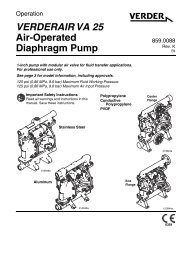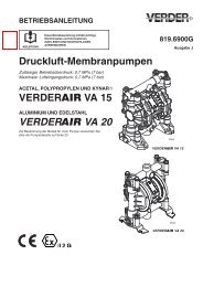
V E R D E R VA 40 Air-Operated Diaphragm Pumps
Warning - Double Diaphragm Pump
Warning - Double Diaphragm Pump
- No tags were found...

Create successful ePaper yourself
Turn your PDF publications into a flip-book with our unique Google optimized e-Paper software.
Service<br />
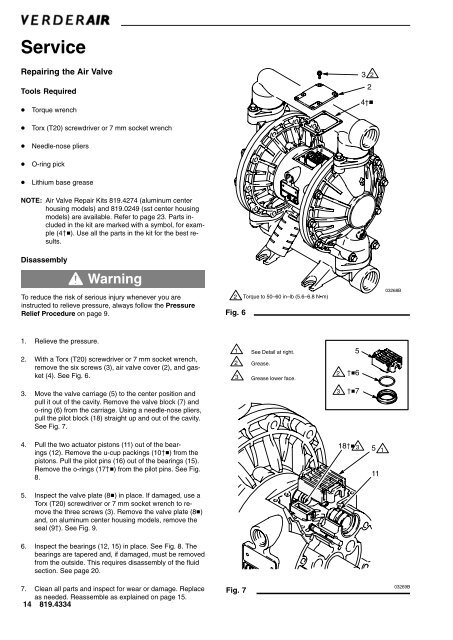
Repairing the <strong>Air</strong> Valve<br />
Tools Required<br />
Torque wrench<br />
3 2<br />
2<br />
4†<br />
<br />
<br />
<br />
<br />
Torx (T20) screwdriver or 7 mm socket wrench<br />
Needle-nose pliers<br />
O-ring pick<br />
Lithium base grease<br />
NOTE: <strong>Air</strong> Valve Repair Kits 819.4274 (aluminum center<br />
housing models) and 819.0249 (sst center housing<br />
models) are available. Refer to page 23. Parts included<br />
in the kit are marked with a symbol, for example<br />
(4). Use all the parts in the kit for the best results.<br />
Disassembly<br />
Warning<br />
To reduce the risk of serious injury whenever you are<br />
instructed to relieve pressure, always follow the Pressure<br />
Relief Procedure on page 9.<br />
2<br />
Fig. 6<br />
Torque to 50–60 in–lb (5.6–6.8 Nm)<br />
03268B<br />
1. Relieve the pressure.<br />
2. With a Torx (T20) screwdriver or 7 mm socket wrench,<br />
remove the six screws (3), air valve cover (2), and gasket<br />
(4). See Fig. 6.<br />
1 See Detail at right.<br />
2 Grease.<br />
3 Grease lower face.<br />
2<br />
5<br />
6<br />
3. Move the valve carriage (5) to the center position and<br />
pull it out of the cavity. Remove the valve block (7) and<br />
o-ring (6) from the carriage. Using a needle-nose pliers,<br />
pull the pilot block (18) straight up and out of the cavity.<br />
See Fig. 7.<br />
3<br />
7<br />
4. Pull the two actuator pistons (11) out of the bearings<br />
(12). Remove the u-cup packings (10) from the<br />
pistons. Pull the pilot pins (16) out of the bearings (15).<br />
Remove the o-rings (17) from the pilot pins. See Fig.<br />
8.<br />
18 3 5 1<br />
11<br />
5. Inspect the valve plate (8) in place. If damaged, use a<br />
Torx (T20) screwdriver or 7 mm socket wrench to remove<br />
the three screws (3). Remove the valve plate (8)<br />
and, on aluminum center housing models, remove the<br />
seal (9). See Fig. 9.<br />
6. Inspect the bearings (12, 15) in place. See Fig. 8. The<br />
bearings are tapered and, if damaged, must be removed<br />
from the outside. This requires disassembly of the fluid<br />
section. See page 20.<br />
7. Clean all parts and inspect for wear or damage. Replace<br />
as needed. Reassemble as explained on page 15.<br />
14 819.4334<br />
Fig. 7<br />
03269B