V E R D E R VA 40 Air-Operated Diaphragm Pumps
Warning - Double Diaphragm Pump
Warning - Double Diaphragm Pump
- No tags were found...

You also want an ePaper? Increase the reach of your titles
YUMPU automatically turns print PDFs into web optimized ePapers that Google loves.
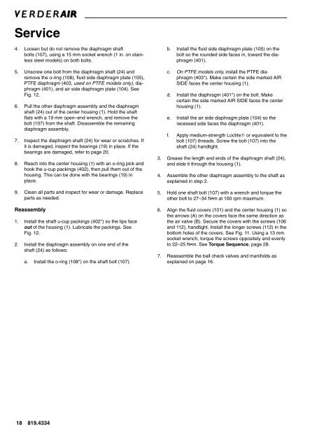
Service<br />
4. Loosen but do not remove the diaphragm shaft<br />
bolts (107), using a 15 mm socket wrench (1 in. on stainless<br />
steel models) on both bolts.<br />
5. Unscrew one bolt from the diaphragm shaft (24) and<br />
remove the o-ring (108), fluid side diaphragm plate (105),<br />
PTFE diaphragm (<strong>40</strong>3, used on PTFE models only), diaphragm<br />
(<strong>40</strong>1), and air side diaphragm plate (104). See<br />
Fig. 12.<br />
6. Pull the other diaphragm assembly and the diaphragm<br />
shaft (24) out of the center housing (1). Hold the shaft<br />
flats with a 19 mm open–end wrench, and remove the<br />
bolt (107) from the shaft. Disassemble the remaining<br />
diaphragm assembly.<br />
7. Inspect the diaphragm shaft (24) for wear or scratches. If<br />
it is damaged, inspect the bearings (19) in place. If the<br />
bearings are damaged, refer to page 20.<br />
8. Reach into the center housing (1) with an o-ring pick and<br />
hook the u-cup packings (<strong>40</strong>2), then pull them out of the<br />
housing. This can be done with the bearings (19) in<br />
place.<br />
9. Clean all parts and inspect for wear or damage. Replace<br />
parts as needed.<br />
Reassembly<br />
1. Install the shaft u-cup packings (<strong>40</strong>2*) so the lips face<br />
out of the housing (1). Lubricate the packings. See<br />
Fig. 12.<br />
2. Install the diaphragm assembly on one end of the<br />
shaft (24) as follows:<br />
a. Install the o-ring (108*) on the shaft bolt (107).<br />
b. Install the fluid side diaphragm plate (105) on the<br />
bolt so the rounded side faces in, toward the diaphragm<br />
(<strong>40</strong>1).<br />
c. On PTFE models only, install the PTFE diaphragm<br />
(<strong>40</strong>3*). Make certain the side marked AIR<br />
SIDE faces the center housing (1).<br />
d. Install the diaphragm (<strong>40</strong>1*) on the bolt. Make<br />
certain the side marked AIR SIDE faces the center<br />
housing (1).<br />
e. Install the air side diaphragm plate (104) so the<br />
recessed side faces the diaphragm (<strong>40</strong>1).<br />
f. Apply medium-strength Loctite or equivalent to the<br />
bolt (107) threads. Screw the bolt (107) into the<br />
shaft (24) handtight.<br />
3. Grease the length and ends of the diaphragm shaft (24),<br />
and slide it through the housing (1).<br />
4. Assemble the other diaphragm assembly to the shaft as<br />
explained in step 2.<br />
5. Hold one shaft bolt (107) with a wrench and torque the<br />
other bolt to 27–34 Nm at 100 rpm maximum.<br />
6. Align the fluid covers (101) and the center housing (1) so<br />
the arrows (A) on the covers face the same direction as<br />
the air valve (B). Secure the covers with the screws (106<br />
and 112), handtight. Install the longer screws (112) in the<br />
bottom holes of the covers. See Fig. 11. Using a 13 mm<br />
socket wrench, torque the screws oppositely and evenly<br />
to 22–25 Nm. See Torque Sequence, page 28.<br />
7. Reassemble the ball check valves and manifolds as<br />
explained on page 16.<br />
18 819.4334