V E R D E R VA 40 Air-Operated Diaphragm Pumps
Warning - Double Diaphragm Pump
Warning - Double Diaphragm Pump
- No tags were found...

You also want an ePaper? Increase the reach of your titles
YUMPU automatically turns print PDFs into web optimized ePapers that Google loves.
Service<br />
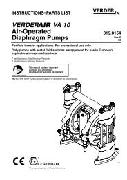
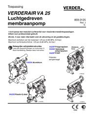
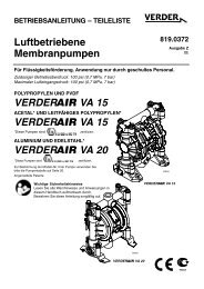
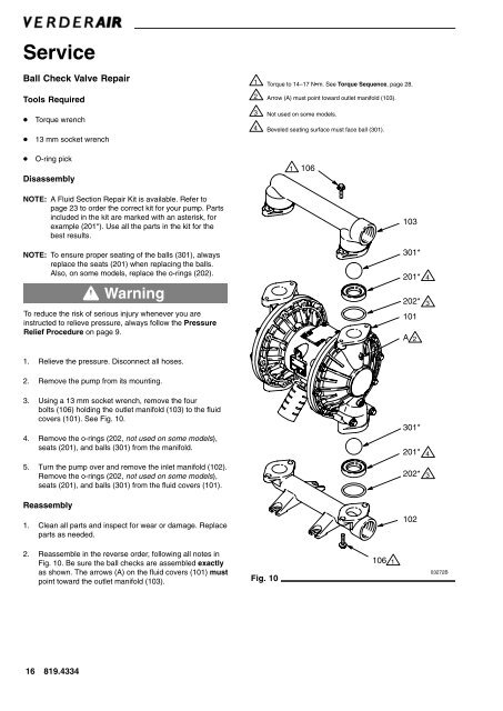
Ball Check Valve Repair<br />
Tools Required<br />
1<br />
2<br />
Torque to 14–17 Nm. See Torque Sequence, page 28.<br />
Arrow (A) must point toward outlet manifold (103).<br />
<br />
<br />
Torque wrench<br />
13 mm socket wrench<br />
3 Not used on some models.<br />
4 Beveled seating surface must face ball (301).<br />
<br />
O-ring pick<br />
Disassembly<br />
1<br />
106<br />
NOTE: A Fluid Section Repair Kit is available. Refer to<br />
page 23 to order the correct kit for your pump. Parts<br />
included in the kit are marked with an asterisk, for<br />
example (201*). Use all the parts in the kit for the<br />
best results.<br />
NOTE: To ensure proper seating of the balls (301), always<br />
replace the seats (201) when replacing the balls.<br />
Also, on some models, replace the o-rings (202).<br />
Warning<br />
To reduce the risk of serious injury whenever you are<br />
instructed to relieve pressure, always follow the Pressure<br />
Relief Procedure on page 9.<br />
103<br />
301*<br />
201*<br />
202*<br />
101<br />
A 2<br />
4<br />
3<br />
1. Relieve the pressure. Disconnect all hoses.<br />
2. Remove the pump from its mounting.<br />
3. Using a 13 mm socket wrench, remove the four<br />
bolts (106) holding the outlet manifold (103) to the fluid<br />
covers (101). See Fig. 10.<br />
4. Remove the o-rings (202, not used on some models),<br />
seats (201), and balls (301) from the manifold.<br />
5. Turn the pump over and remove the inlet manifold (102).<br />
Remove the o-rings (202, not used on some models),<br />
seats (201), and balls (301) from the fluid covers (101).<br />
Reassembly<br />
1. Clean all parts and inspect for wear or damage. Replace<br />
parts as needed.<br />
301*<br />
201*<br />
202*<br />
102<br />
4<br />
3<br />
2. Reassemble in the reverse order, following all notes in<br />
Fig. 10. Be sure the ball checks are assembled exactly<br />
as shown. The arrows (A) on the fluid covers (101) must<br />
point toward the outlet manifold (103). Fig. 10<br />
106<br />
1<br />
03272B<br />
16 819.4334