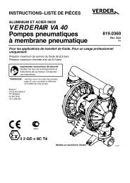
V E R D E R VA 40 Air-Operated Diaphragm Pumps
Warning - Double Diaphragm Pump
Warning - Double Diaphragm Pump
- No tags were found...

Create successful ePaper yourself
Turn your PDF publications into a flip-book with our unique Google optimized e-Paper software.
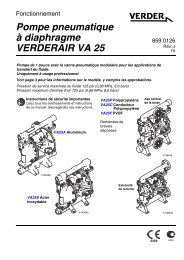
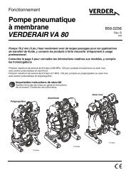
Installation<br />
Changing the Orientation of the Fluid Inlet and<br />
Outlet Ports<br />
The pump is shipped with the fluid inlet (R) and outlet (S)<br />
ports facing the same direction. See Fig. 3. To change the<br />
orientation of the inlet and/or outlet port:<br />
1. Remove the screws (106) holding the inlet (102) and/or<br />
outlet (103) manifold to the covers (101).<br />
2. Reverse the manifold and reattach. Install the screws<br />
and torque to 14–17 Nm. See Torque Sequence, page<br />
28.<br />
KEY<br />
N 1/2 npt(f) <strong>Air</strong> Inlet Port<br />
P Muffler; <strong>Air</strong> Exhaust Port<br />
is 3/4 npt(f)<br />
R* 1–1/2 in. bspt Fluid<br />
Inlet Port<br />
S* 1–1/2 in. bspt Fluid<br />
Outlet Port<br />
1 Torque to 14–17 Nm. See Torque Sequence,<br />
page 28.<br />
2 Torque to 22–25 Nm. See Torque Sequence,<br />
page 28.<br />
101 Covers<br />
102 Fluid Inlet Manifold<br />
103 Fluid Outlet Manifold<br />
106 Manifold and Cover<br />
Screws<br />
112 Bottom Cover Screws<br />
Aluminum Model Shown<br />
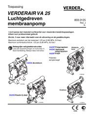
Fluid Pressure Relief Valve<br />
Caution<br />
Some systems may require installation of a pressure relief<br />
valve at the pump outlet to prevent overpressurization and<br />
rupture of the pump or hose. See Fig. 4.<br />
Thermal expansion of fluid in the outlet line can cause overpressurization.<br />
This can occur when using long fluid lines<br />
exposed to sunlight or ambient heat, or when pumping from<br />
a cool to a warm area (for example, from an underground<br />
tank).<br />
Overpressurization can also occur if the pump is being used<br />
to feed fluid to a piston pump, and the intake valve of the<br />
piston pump does not close, causing fluid to back up in the<br />
outlet line.<br />
KEY<br />
R* 1–1/2 in. bspt Fluid Inlet Port<br />
S* 1–1/2 in. bspt Fluid Outlet Port<br />
V Pressure Relief Valve (Order Part No. 819.0159)<br />
103<br />
106<br />
1<br />
1<br />
Install valve between fluid inlet and outlet ports.<br />
2 Connect fluid inlet line here.<br />
S<br />
3<br />
Connect fluid outlet line here.<br />
N<br />
S<br />
3<br />
2<br />
106<br />
V<br />
1<br />
112<br />
101<br />
2<br />
2<br />
P<br />
R<br />
Fig. 3<br />
102<br />
03263B<br />
Fig. 4<br />
R<br />
03461B<br />
* On pumps 810.0195, 810.0196, 810.0197, and 810.0198, inlet and outlet ports are 1–1/2 in. npt threads.<br />
819.4334 7