DiMAX Navigator
DiMAX® Navigator - Massoth
DiMAX® Navigator - Massoth

You also want an ePaper? Increase the reach of your titles
YUMPU automatically turns print PDFs into web optimized ePapers that Google loves.
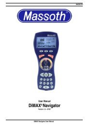
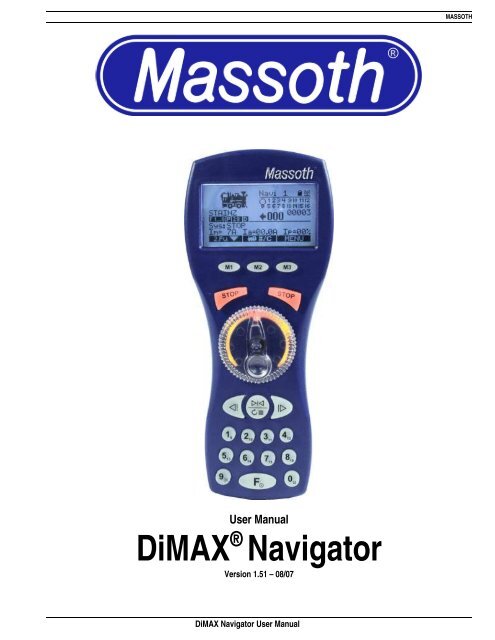
MASSOTH<br />
User Manual<br />
<strong>DiMAX</strong> ® <strong>Navigator</strong><br />
Version 1.51 – 08/07<br />
<strong>DiMAX</strong> <strong>Navigator</strong> User Manual
MASSOTH<br />
Table of Contents<br />
Index<br />
Page<br />
I. Safety Details and Warnings 3<br />
I. Scope of Supply 4<br />
II. Batteries for Wireless Operation 4<br />
1. General Description 4<br />
1.1 Features of the <strong>DiMAX</strong> <strong>Navigator</strong> 5<br />
1.1.1 Form and Function 5<br />
1.1.2 <strong>Navigator</strong> Compatibility with Other Digital Central Stations 5<br />
1.1.3 <strong>Navigator</strong> Function Limitations with the LGB® 55006 MTS III Central Station 5<br />
1.1.4 Hook-Up 6<br />
1.1.5 Wireless Operation 6<br />
1.2 Control Elements 7<br />
1.2.1 Display Graphic 8<br />
1.2.2 Display 9<br />
1.2.3 Menu Keys 10<br />
1.2.4 Stop Keys 10<br />
1.2.5 Controlling the Primary Function 10<br />
1.2.6 Controlling the Secondary Function 10<br />
1.2.7 Keyboard 11<br />
1.2.8 Light Function 11<br />
1.2.9 Loco Selection Key 11<br />
1.2.10 Function Level / On/Off 11<br />
2. Starting the Operation 11<br />
2.1 Switching ON/OFF 11<br />
2.2 Selecting the Loco Address 11<br />
2.3 The First Test Run 12<br />
3. Loco Configuration 12<br />
3.1 Access to Loco Configuration Menu 12<br />
3.1.1 Delete Locos 12<br />
3.1.2 Speed Step Configuration 12<br />
3.1.3 Protocol for Function Commands – NMRA Parallel/MTS Serial Selection 12<br />
3.1.4 F Key Configuration 13<br />
3.1.5 Loco Icon Selection 13<br />
3.1.6 Loco Name Definition 14<br />
3.1.7 Save Configuration 15<br />
3.1.8 Defining Additional Locos 15<br />
3.1.9 Loco Log On 15<br />
3.1.10 Loco Log Off 16<br />
<strong>DiMAX</strong> <strong>Navigator</strong> User Manual 1
MASSOTH<br />
3.1.11 Re-Gaining Control After Switching Locos 16<br />
3.1.12 Selecting a Logged-On Loco 16<br />
3.1.13 Analog Loco 17<br />
3.2 Driving Operation 17<br />
3.2.1 Additional Functions during Driving Operations 17<br />
4. Secondary Function 17<br />
4.1 Info Mode 18<br />
4.2 Switching Commands 18<br />
4.3 Operating Turnout Routes 18<br />
4.4 Second Loco 19<br />
5. General Settings 19<br />
5.1 Consist (Multi-Heading) 20<br />
5.2 Decoder Programming 21<br />
5.2.1 Loco Address 21<br />
5.2.2 CV Reading 21<br />
5.2.3 CV Programming 22<br />
5.2.4 CV Writing Bit By Bit 22<br />
5.2.5 Register Programming / Indirect CV Writing 22<br />
5.2.6 POM Programming on the Main Track 23<br />
5.2.7 Switch Decoder Programming 23<br />
5.3 Programming Automatic Functions 23<br />
5.3.1 Turnout Route Programming 24<br />
5.3.2 Programming Consists 24<br />
5.3.3 Automatic Operation 24<br />
5.3.4 Automatic Turnout Operation 26<br />
5.4 <strong>Navigator</strong> Configuration 28<br />
5.4.1 Background Lighting 28<br />
5.4.2 Emergency Stop Mode 28<br />
5.4.3 Change Language 29<br />
5.4.4 Programming ID-Number 29<br />
5.4.5 Blocking Functions 29<br />
5.4.6 Factory Setting 30<br />
5.5 Transmitter 30<br />
5.5.1 Transmitter Installation 30<br />
5.5.2 Transmitter Configuration 31<br />
5.5.2.1 Channel Selection 31<br />
5.5.2.2 Frequency Band Selection 31<br />
5.5.2.3 Turn-Off Time 31<br />
5.5.2.4 Battery Charging Function 32<br />
5.6 Central Station Configuration 32<br />
6. Loco Icons 32<br />
7. Software Update 35<br />
<strong>DiMAX</strong> <strong>Navigator</strong> User Manual 2
MASSOTH<br />
8. Technical data 35<br />
9. Warranty 36<br />
10. Warranty Claims 36<br />
11. Special Hints 36<br />
12. Glossary 37<br />
13. Technical Support 40<br />
14. Manufacturer Information 40<br />
Please read this section prior to beginning installation or operation<br />
Welcome to the World of <strong>DiMAX</strong><br />
On behalf of Massoth Electronics USA, thank you for purchasing the Massoth <strong>DiMAX</strong> <strong>Navigator</strong>. Offering<br />
intuitive operation and unparalleled features, the <strong>DiMAX</strong> <strong>Navigator</strong> sets the standard for DCC cab controllers.<br />
The <strong>Navigator</strong> is designed for use with the <strong>DiMAX</strong> bus, found on all Massoth <strong>DiMAX</strong> central stations and the<br />
LGB ® 55006 MTS III central station. Additionally, the <strong>Navigator</strong> is compatible with the Lenz XpressNET and<br />
Digitrax LocoNet bus protocols.<br />
Massoth Elektronik GmbH, located in Seeheim, Germany, is a Recommended LGB ® Partner and serves as the<br />
exclusive supplier of digital sound systems and MTS components for LGB ® trains. A family-owned company,<br />
Massoth designs and builds innovative electronic components for the model railway and hobby industry.<br />
The <strong>DiMAX</strong> <strong>Navigator</strong> is designed for years of enjoyment. Please read this manual to learn important care,<br />
safety, installation and operation tips. Additional information regarding this product can be found online at<br />
www.massoth.com or by visiting our online forum at http://forum.massoth.com/ .<br />
Enjoy the world of digital command control with the <strong>Navigator</strong>!<br />
PLEASE READ THIS SECTION PRIOR TO BEGINNING INSTALLATION OR OPERATION!<br />
I. Safety Details and Warnings<br />
• This product is not suitable for children under 8 years of age. This product may have sharp edges and<br />
inappropriate handling may cause injuries.<br />
• The <strong>DiMAX</strong> <strong>Navigator</strong> is for use exclusively with digitally-controlled model railroads. The <strong>DiMAX</strong><br />
<strong>Navigator</strong> must only be operated with compatible components identified in this manual.<br />
• Never connect the bus connectors to your telephone line or to appliances with similar or same sockets.<br />
The result will be irreparable or costly.<br />
• Do not drop shake or drop the <strong>Navigator</strong>. Exposure to such shocks may damage the product.<br />
• Do not expose the <strong>DiMAX</strong> <strong>Navigator</strong> to prolonged periods of direct heat, sunlight, or moisture. This may<br />
affect the operation or damage the product.<br />
• Do not open the <strong>DiMAX</strong> <strong>Navigator</strong> unless it is required by the Wireless Transmitter Retrofit Manual.<br />
Unauthorized opening may result in damage.<br />
• Never use household chemical cleansers, abrasive cleaning pads, or solvents to clean this product.<br />
• DANGER – EXPLOSION RISK - Do not operate the <strong>Navigator</strong>’s battery charging feature when nonrechargeable<br />
batteries are installed.<br />
• Improper use of this product voids all warranty.<br />
• Products and specifications are subject to change without notice.<br />
<strong>DiMAX</strong> <strong>Navigator</strong> User Manual 3
MASSOTH<br />
II.<br />
Scope of Supply<br />
The following components are included with purchase of the <strong>Navigator</strong>:<br />
• 1 x <strong>DiMAX</strong> <strong>Navigator</strong><br />
• 1 x <strong>DiMAX</strong> bus cable<br />
• 1 x User manual<br />
Please contact Massoth Electronics USA if any of the above components are missing.<br />
III. Batteries for Wireless Operation<br />
Please note, batteries are not included with this product. For peak performance, Massoth recommends AA<br />
alkaline or rechargeable (NiMH or NiCd) batteries for your wireless <strong>Navigator</strong>. The <strong>Navigator</strong> features the<br />
ability to charge rechargeable batteries during tethered operation. To enable charging, select Wireless<br />
Transmitter Configuration from the <strong>Navigator</strong> Configuration menu.<br />
Wireless operation requires the <strong>Navigator</strong> be fitted with a wireless transmitter.<br />
The Wireless Transmitter Configuration menu is only visible when a wireless transmitter has been installed.<br />
Batteries are not required for tethered operation of the <strong>Navigator</strong>.<br />
DANGER – EXPLOSION RISK - Do not operate the <strong>Navigator</strong>’s battery charging feature when non-rechargeable<br />
batteries are installed.<br />
1. General Description<br />
The <strong>DiMAX</strong> <strong>Navigator</strong> is a state-of-the-art cab control for digital model railroads. The <strong>DiMAX</strong> <strong>Navigator</strong> offers<br />
unparalleled features, including:<br />
• Large, back-lit display with intuitive menu format<br />
• Configure loco address with alphanumeric locomotive names and locomotive graphics<br />
• Locomotive graphic library includes LGB® models and many popular G-scale models<br />
• 10,239 loco addresses (a.k.a. 4-digit addressing)<br />
• 14/28/128 speed step operation<br />
• 2,048 switch addresses<br />
• 32 Automatic functions for locomotive and switch (turnout) control<br />
• 5 different modes for decoder programming<br />
• 16 programmable switch routes with up to 15 switch elements per route<br />
• NMRA functions F1 through F16<br />
• Compatibility with NMRA parallel and LGB ® MTS serial function processing<br />
• Bi-Directional Wireless Operation (available as an upgrade for tethered versions)<br />
• Consisting – operate up to 16 consists with as many as four locomotives per consist<br />
• Programmable STOP keys<br />
• Split screen display, illuminated dial control and illuminated multi-function keypad allows simultaneous<br />
operation of two devices:<br />
o control two locomotives (one via the illuminated dial and a second via directional buttons)<br />
o control one locomotive (via illuminated dial) and one switch/switch route (via directional buttons)<br />
• Blocking Function to prevent accidental changes (ideal for children!)<br />
• System status menu displays current draw, software version, etc.<br />
<strong>DiMAX</strong> <strong>Navigator</strong> User Manual 4
MASSOTH<br />
• Multi-protocol operation – compatible with Massoth <strong>DiMAX</strong>, Lenz XpressNET, and Digitrax Loconet bus<br />
protocol (only RC)<br />
• Downloadable software updates (requires Massoth PC Interface #8175001)<br />
• Accu charging function<br />
1.1. Features of the <strong>DiMAX</strong> <strong>Navigator</strong><br />
1.1.1. Form and Functions<br />
Massoth Electronics defines a new standard with the ergonomically shaped <strong>DiMAX</strong> <strong>Navigator</strong>. The handheld<br />
cab is designed to facilitate right handed and left handed operation. The large backlit display provides detailed<br />
information for locomotives, switches and other devices on the model railway.<br />
The <strong>DiMAX</strong> <strong>Navigator</strong> offers the unique capability of allowing the user to execute two separate functions concurrently,<br />
e.g. controlling a locomotive while operating turnouts. In additional to controlling turnouts, the second<br />
function can be used to control switch routes or control a second locomotive.<br />
1.1.2. <strong>Navigator</strong> Compatibility with Other Digital Central Stations<br />
The <strong>DiMAX</strong> <strong>Navigator</strong> is designed to operate with all Massoth <strong>DiMAX</strong> bus compatible central stations, e.g., Di-<br />
MAX 800Z, <strong>DiMAX</strong>1200Z , <strong>DiMAX</strong> 1210Z, and LGB ® MTS III. The <strong>DiMAX</strong> <strong>Navigator</strong> may also be used in conjunction<br />
with central stations operating the XpressNet© or LocoNet© bus protocols, e.g., Lenz ® , UHLENB-<br />
ROCK ® , ROCO ® , FLEISCHMANN ® , and PIKO ® .<br />
1.1.3. <strong>Navigator</strong> Function Limitations with the LGB® 55006 MTS III Central Station<br />
The LGB ® 55006 MTS III Central Station operates a simplified version of the <strong>DiMAX</strong> operating system. When<br />
combined with the Massoth <strong>Navigator</strong>, the MTS III central station offers enhanced operations. However, to<br />
operate the full range of features discussed in this manual, the <strong>Navigator</strong> must be operated in tandem with a<br />
Massoth central station.<br />
When operating the Massoth <strong>Navigator</strong> with the LGB ® 55006 MTS III central station, please note the following:<br />
• Only speed steps 14 and 28 available. MTS III is limited to 14 speed steps without the <strong>Navigator</strong>.<br />
(Note: Loco decoders must be programmed for the correct speed step setting (see CV#29) to enable<br />
reception of 28 speed step commands.)<br />
• MTS III does not offer an isolated programming track, therefore<br />
o Only short address (CV #1) programming is available.<br />
o The <strong>Navigator</strong> cannot read CV values or write CVs (other than CV#1)<br />
o<br />
(Note: since Software Version 1.5 you can write CVs!)<br />
Operations Mode Programming (a.k.a. Programming-on-the-Main or PoM) and Register Mode<br />
programming not available.<br />
• No automatic function routines are available.<br />
• Wireless operation requires the Massoth RF Receiver – Item #8132001. The Massoth <strong>Navigator</strong> operating<br />
frequency differs from that of the current MTS wireless devices. Also note, the <strong>Navigator</strong> wireless<br />
components are bi-directional; the MTS wireless components are uni-directional.<br />
<strong>DiMAX</strong> <strong>Navigator</strong> User Manual 5
MASSOTH<br />
1.1.4. Hook Up<br />
The <strong>DiMAX</strong> <strong>Navigator</strong> may be used in tethered (cable) mode or wireless mode. When switched ON, the <strong>DiMAX</strong><br />
<strong>Navigator</strong> will log into the central station via the bus cable. When communication is unavailable via the cabled<br />
bus port, the <strong>Navigator</strong> will log in via wireless mode. If no connection can be established with the central station,<br />
an error message will be displayed. A symbol in the upper right hand corner of the <strong>Navigator</strong> display communicates<br />
the current connection mode.<br />
1.1.5. Wireless Operation (Needs software version V1.20)<br />
When operating in wireless mode, the <strong>Navigator</strong>’s communication remains bi-directional. As a result, the<br />
<strong>Navigator</strong> can send commands to and receive updated information from the central station and other bus<br />
components. The <strong>DiMAX</strong> <strong>Navigator</strong> radio transmission frequency differs from that of the LGB ® MTS RF<br />
Transmitter 55051, therefore both systems can be used concurrently without interference.<br />
Compared to other DCC wireless throttles, the <strong>Navigator</strong> offers superior wireless data transfer speed and the<br />
operational range. A range of 300 feet is typical for outdoor use, but tests have revealed performance at up to<br />
1000 feet.<br />
Range and performance can be adversely affected by certain building materials and interference with other<br />
wireless devices, including: computer components, Blue Tooth devices, electronic garage door openers, and<br />
wireless headsets. In extreme circumstances, such environmental factors may render wireless operation<br />
impossible.<br />
When operating the wireless <strong>Navigator</strong> in the presence of radio frequency interference, changing the channel<br />
may improve performance. (See 5.5.2.1. in this manual)<br />
If multiple RC <strong>Navigator</strong>s are used every <strong>Navigator</strong> needs to be set to a seperate ID.<br />
<strong>DiMAX</strong> <strong>Navigator</strong> User Manual 6
MASSOTH<br />
1.2. Control Elements<br />
The <strong>DiMAX</strong> <strong>Navigator</strong> features various control devices and display indicators.<br />
Fig.<br />
A<br />
M<br />
B<br />
C<br />
D<br />
E<br />
G<br />
H<br />
I<br />
F<br />
Description<br />
Display<br />
Menu-Keys<br />
Right-hand Stop Key<br />
Left-hand Stop Key<br />
Transparent Dial Knob, Throttle for Speed Control<br />
Secondary Function Control Keys (programmable)<br />
Key-Pad / F-Function Keys<br />
Light function Key / #9 Key<br />
Locomotive Selection Key / #0 Key<br />
Function Level Selection / ON/OFF Key<br />
<strong>DiMAX</strong> <strong>Navigator</strong> User Manual 7
MASSOTH<br />
1.2.1. Display Graphic (V1.30)<br />
<strong>DiMAX</strong> <strong>Navigator</strong> User Manual 8
MASSOTH<br />
1.2.2. DISPLAY A<br />
The easy-to-read display offers detailed information regarding the status of the current driving locomotive and<br />
other devices on the model railway. The following information is communicated via the <strong>Navigator</strong> display<br />
interface: loco icon, loco address, selected number of driving speed steps, selected protocol for function<br />
commands (NMRA parallel or MTS serial), status for functions F1 - F16, driving direction, driving speed (shown<br />
as integer speed step value and as a bar graph), and more.<br />
Measuring 2-1/8” x 1-1/32” (54mm x 26mm), the backlit display provides ideal visibility in darkened rooms. The<br />
back light may also be switched off to extend battery life during wireless operation.<br />
This is the general display arrangement:<br />
The status bar:<br />
The main function array:<br />
The auxiliary function array shows the following indications after start:<br />
The menu bar shows the current assignment of the three menu keys: M1 , M2 , M3 .<br />
<strong>DiMAX</strong> <strong>Navigator</strong> User Manual 9
MASSOTH<br />
1.2.3. Menu Keys M<br />
The menu keys M1 , M2 , M3 are assigned different functions depending on the current menu selection. The<br />
current key functions are shown in the black background menu bar at the bottom of the display, e.g.:<br />
1.2.4. Stop Keys B + C<br />
The <strong>DiMAX</strong> <strong>Navigator</strong> features two programmable stop keys. The stop keys work independently of each other,<br />
allowing each key to be programmed to perform a different stop function. For example, one key can be<br />
programmed to trigger an Emergency Stop, removing power from the track while the second key can be<br />
programmed to send a ‘Broadcast Packet Stop’ command, bringing all locomotives safely to a halt without<br />
removing power from the rails. The function assignment of the stop keys is programmable for each <strong>DiMAX</strong><br />
<strong>Navigator</strong>, allowing multiple <strong>Navigator</strong> users on the same layout to each customize their handheld. (See 5.4.2.<br />
of this manual for programming information.) With the factory default setting, the right hand stop key B<br />
initiates an Emergency Stop and the left hand stop key C cancels the emergency stop.<br />
1.2.5. Controlling the Primary Function D<br />
The primary function of the <strong>DiMAX</strong> <strong>Navigator</strong> is controlled by the transparent dial knob D . The dial knob<br />
controls direction and speed of a locomotive or a locomotive consist. The zero point of the dial knob is<br />
highlighted by a red background spotlight. In addition, the dial knob may be backlit in a similar fashion to the<br />
display. Individual programming of these features is accomplished in the <strong>Navigator</strong>’s configuration menu.<br />
1.2.6. Controlling the Secondary Function E<br />
The secondary control function of the <strong>DiMAX</strong> <strong>Navigator</strong> is accomplished with the three keys beneath the round<br />
dial knob D . The secondary function can control a second locomotive or control switches, switch routes or signals.<br />
The primary and secondary function controls can be operated simultaneously, making the <strong>DiMAX</strong> <strong>Navigator</strong><br />
uniquely suited to the complex operations of model railways.<br />
<strong>DiMAX</strong> <strong>Navigator</strong> User Manual 10
MASSOTH<br />
1.2.7. Keyboard G<br />
The keyboard of the <strong>DiMAX</strong> <strong>Navigator</strong> can be used to trigger up to sixteen functions (F1 – F16). The F-Key F<br />
shifts control between the first and second function level (first function level = function 1 to function 8, second<br />
function level = function 9 to function 16). On each key, second function level values are printed as subscripts<br />
to the first function level values.<br />
1.2.8. Light Function H<br />
The light key H controls the locomotive headlights. The light function, F0, is an additional function to the previously<br />
discussed functions, F1-F16.<br />
1.2.9. Loco Selection Key I or M2<br />
Pressing the Loco Selection Key I or M2 leads to the locomotive selection menu of the <strong>DiMAX</strong> <strong>Navigator</strong>.<br />
There are several methods of selecting a locomotive. For more detailed information, please see section 3.1.7.<br />
1.2.10. Function Level / On/Off F<br />
The F key F defines the function level for the numbered keys 1-8. The current setting is indicated below the locomotive<br />
name on the <strong>Navigator</strong> display. The first level is displayed as F1...8 . Accordingly, the second level is<br />
displayed F9..16 . Pressing the F-key F toggles control between the first level,<br />
F1...8 and the second level F9..16 (You can switch the keyboard from the secondary function back to the<br />
primary function by pressing key F again.)<br />
When operating the <strong>DiMAX</strong> <strong>Navigator</strong> in wireless mode, press the F-key F to turn the <strong>Navigator</strong> ON. To shutdown<br />
the <strong>Navigator</strong>, press and hold the F-key F .<br />
2. Starting the Operation<br />
2.1. Switching ON/OFF (Needs software version V1.30)<br />
• During tethered operation the <strong>Navigator</strong> starts automatically<br />
• In wireless operation the <strong>Navigator</strong> must be switched ON with the F-key F<br />
• Depressing the F-key F for more than one second switches OFF the <strong>Navigator</strong>.<br />
2.2. Selecting the Loco Address (Needs software version V1.30)<br />
After pressing the locomotive selection key I or M2 the <strong>DiMAX</strong> <strong>Navigator</strong> displays the locomotive selection<br />
window. Enter the loco address via the keypad, for example, loco address 0003 After confirming the address<br />
by pressing M3 , the loco is ready for driving operation and the <strong>DiMAX</strong> <strong>Navigator</strong> automatically returns to the<br />
driving mode screen. Default locomotive addresses are typically listed in the locomotive manual or the decoder<br />
manual. For most NMRA DCC decoders, the default address is 3.<br />
<strong>DiMAX</strong> <strong>Navigator</strong> User Manual 11
MASSOTH<br />
2.3. The First Test Run<br />
Congratulations! After entering the loco address and pressing M3 to confirm, the loco is ready to be controlled<br />
with the transparent dial knob. With the <strong>Navigator</strong> factory default settings, the locomotive will be controlled with<br />
28 speed steps and parallel data processing. More detailed properties like loco icon, loco name, etc., will be<br />
defined in Loco Configuration. (Please see section 3.)<br />
Please note that lights of locomotives configured for 14 speed steps (see locomotive decoder CV#29) will not<br />
display correctly if the locomotives are controlled with 28 speed steps. The same is true for locomotives configured<br />
for 28 speed steps that are controlled with 14 speed steps. In these cases, the lights of the locomotives<br />
may flicker on/off with each advancing speed step or the lights may not work at all.<br />
3. Loco Configuration<br />
3.1. Access to Loco Configuration Menu (Needs software version V1.30)<br />
The loco configuration menu is used to define the attributes of a locomotive, for example, configured speed<br />
steps, selected protocol for function commands, or the locomotive icon. To enter the loco configuration<br />
menu, press and hold the M2 key for about 2 seconds.<br />
3.1.1. Delete Locomotives (Needs software version V1.30)<br />
The first displayed window of the loco configuration menu allows configured locomotives to be deleted. To delete<br />
the locomotive currently displayed, press the M1 key.<br />
3.1.2. Speed Step Configuration (Motorola operation from software version V1.40)<br />
Upon selecting the loco configuration menu, the first window is used to select speed step configuration. Toggle<br />
between 14D , 28D , 128D and 14M speed steps by pressing the M2 key. D stands for NMRA DCC operation;<br />
M stands for Motorola operation. Confirm the selection with the M3<br />
key. After pressing the “OK” key, M3 , the next window is automatically displayed.<br />
Please note, MTS III only allows 14D and 28D speed step operation.<br />
3.1.3. Protocol for Function Commands – NMRA Parallel/MTS Serial Selection<br />
Toggle between the NMRA Parallel (“P”) and MTS Serial (“S”) function command protocols by pressing key M2.<br />
Confirm the selection by pressing the M3 key only if wishing to avoid configuration of the F-keys (see 3.1.4.<br />
in this manual). Please check the decoder or locomotive manual to determine the appropriate protocol for function<br />
commands.<br />
<strong>DiMAX</strong> <strong>Navigator</strong> User Manual 12
MASSOTH<br />
Notes:<br />
LGB ® onboard decoders, featuring the silver/black ‘Analog and Digital’<br />
sticker may be controlled with NMRA Parallel commands.<br />
LGB ® locomotives equipped with a Decoder Interface or a Direct Decoder<br />
Interface and fitted with an LGB ® 55021 decoder are controlled by MTS<br />
Serial commands. (Unless the 55021 decoder and locomotive circuit board<br />
have received a Massoth “P” upgrade.)<br />
LGB ® locomotives equipped with a DCC Interface may be controlled with<br />
NMRA Parallel commands.<br />
3.1.4. F-Key Configuration (Needs software version V1.40)<br />
The momentary operation operates the F function like a toggle switch; hitting the key once switches the function<br />
on. The second push switches the function off, e.g. lights, smoke generator etc.<br />
The continuous operation keeps the function activated as long as the key is pressed.<br />
The F-key configuration window shows you the selection of your operation (momentary or continuous) e.g.:<br />
when the function key # 8 is highlighted, the continuous mode is selected for the F8 function. When the<br />
function key # 8 is on normal background: the standard or momentary mode is selected for the F8 function.<br />
In the momentary operation e.g. the whistle will be triggered by hitting the respective F-key once and brief<br />
without any further influence to the triggered whistle.<br />
However, in continuous operation the whistle is active as long as the F-key is pressed. Releasing the F-key<br />
ends the whistle.<br />
Confirm your selection with the M3 key.<br />
This F-key operation works with sound, light, smoke, or any other special function. Full use of the continuous<br />
operation function with sound can only be assured with sound units supporting this feature. The eMOTION XLS<br />
Sound Decoder and some limited brands provide this feature.<br />
3.1.5. Loco Icon Selection<br />
Use keys M1 and M2 to scroll through all loco icons available. In addition you may choose your locomotive<br />
icon via the number key pad to select the locomotive icon directly. (Please, see 7. Locomotive Icons in this manual.)<br />
Confirm your selection by pressing key M3 .<br />
<strong>DiMAX</strong> <strong>Navigator</strong> User Manual 13
MASSOTH<br />
3.1.6. Loco Name Definition<br />
This window will automatically open after you’ve pressed M3 in the above mentioned step.<br />
Now, check for the blinking cursor. Press M2 for scrolling forward through the list of characters (choices are<br />
shown below). Use M1 for moving backwards.<br />
0 1 2 3 4 5 6 7 8 9 A B C D E F G H I J<br />
K L M N O P Q R S T U V W X Y Z - / _<br />
Select by scrolling through the characters – see choices below - with keys M1 (forward) and M2 (backward).<br />
Once the window shows your selected character use the right hand arrow key to move the cursor to the right<br />
. The previous character will be shown solid while the cursor in the new position keeps blinking during<br />
your next selection. Now you are ready to define the next character. You may use up to ten (10) characters for<br />
your locomotive name.<br />
Please note that a blank character is located between the “/” and the “0”.<br />
E.g. choose “V51” as the locomotive type or “V 51 Jack” as the locomotive V51 of your fellow model railroader<br />
Jack. End the definition of the loco name with the round stop key of the second loco function. To delete “Jack”<br />
from the locomotive name, move the cursor between “V51” and “Jack” and press the stop key . After<br />
selecting OK the new loco name will be stored and the correct name will be shown next time you select this<br />
locomotive.<br />
This menu allows you to define your personal favorite locomotive name which will be displayed beneath the<br />
loco icon from now on in the normal driving mode. Also, when utilizing the loco driving function in the secondary<br />
function the loco name will be shown as well. In this case the loco name is displayed beneath the loco address.<br />
The name of the locomotive is only stored in the <strong>Navigator</strong>. Thus a locomotive may have different names on<br />
different <strong>Navigator</strong>s. That means: when using several <strong>Navigator</strong>s at the same time, each user may define his<br />
personal choice name for the same locomotive.<br />
<strong>DiMAX</strong> <strong>Navigator</strong> User Manual 14
MASSOTH<br />
3.1.7. Save Configuration<br />
Once you have finalized the configuration of your locomotive, please save your entries. Pressing M2 will save<br />
your data permanently in the central station, so when the central station is switched off, your setting will be<br />
available the next time you switch it on. Saving with M3 will keep the data only during the duration of your<br />
current operation, so when the central station is switched off, your settings will NOT be available the next time<br />
you switch it on.<br />
When you start your operation the next time the last selected locomotive will show up in the driving mode.<br />
However this will happen ONLY if you have saved the data with M2 in the central station.<br />
3.1.8. Defining Additional Locos<br />
To define additional locos, please proceed according to chapter 3. of this manual.<br />
3.1.9. Loco Log On (Needs software version V1.30)<br />
Data of already defined locomotives are stored in the central station and the <strong>Navigator</strong>. All stored locomotives<br />
will be displayed in the loco selection window (see graphic below). Scroll through your stored locomotives with<br />
M2 and select with M3 .<br />
OR – in case you know the loco address of your choice locomotive you may enter that address directly via the<br />
key pad and confirm this with M3 .<br />
In case you enter an unknown address, this will be accepted as a new active address for a new locomotive<br />
which needs to be configured later. To exit the loco selection window without choosing a locomotive press the<br />
M3 key.<br />
<strong>DiMAX</strong> <strong>Navigator</strong> User Manual 15
MASSOTH<br />
3.1.10. Loco Log Off (Needs software version V1.30)<br />
You do not have access to a locomotive that is already selected by another user. The other user/ <strong>Navigator</strong> has<br />
to log off his locomotive before you are able to run this locomotive with your <strong>Navigator</strong>. Opening the loco selection<br />
window with M2 or 0# automatically logs off the locomotive.<br />
NOTE: the management of locomotives is accomplished in the digital central station. When you select one of<br />
the locomotives available, this locomotive will be marked as occupied and can not be selected by other users.<br />
This does not depend upon the operational status of the locomotive.<br />
A driving locomotive is always logged off “passive” because it still is receiving data from the central station.<br />
The locomotive is only logged off from the control bus and may be selected by other users. If you log off a locomotive<br />
that is not moving it is logged off “active”. This means, it is logged off in the central station and it is<br />
not listed as active anymore. This can be checked easily in the display of the central station as the number of<br />
the active locomotives is always displayed in the upper right corner of the display.<br />
3.1.11. Re-Gaining Control After Switching Locos<br />
Example: You are running loco # 1. Then you want to run loco # 2. So, you select loco # 2 on the <strong>Navigator</strong> as<br />
loco #1 is still running and you drive loco #2. Now, you do not have direct access to loco #1 anymore. Loco #1<br />
is logged off “passive”.<br />
To return to loco #1 you have to select loco #1, again. Initially, the position of the speed dial knob will not match<br />
the current speed and driving direction of loco #1. This needs to be synchronized.<br />
As a hint the respective part of the dial where loco #1 is actually running is backlit and blinking. Turn the dial<br />
into this direction until the light stops blinking. This indicates that you re-gained full control of loco #1.<br />
3.1.12. Selecting a Logged-On Loco (Needs software version V1.10)<br />
You cannot get access to a locomotive that is already selected by another user (see graphic below). The other<br />
user/ <strong>Navigator</strong> has to log off this locomotive for you to be able to control this locomotive with your <strong>Navigator</strong>.<br />
Open the loco selection window with M2 or 0# and this loco will be logged off automatically, regardless if it<br />
is driving or not.<br />
<strong>DiMAX</strong> <strong>Navigator</strong> User Manual 16
MASSOTH<br />
3.1.13. Analog Loco<br />
The <strong>DiMAX</strong> <strong>Navigator</strong> does also control analog locomotives. The address of an analog loco is generally “0”. Locomotive<br />
properties like speed steps and functions cannot be defined for an analog locomotive. A loco configuration<br />
is not possible, the analog locomotive is displayed with the icon of an analog throttle.<br />
NOTE: The digital AC on the track may cause analog locomotives to emit a high frequent sound. In general<br />
this does not have an impact on the electronics of your locomotive. (Please check your manufacturer’s manual<br />
on this topic).<br />
3.2. Driving Operation<br />
As usual the locomotive is controlled by the transparent dial knob. With the dial knob is in the middle position<br />
the loco is not running and speed step 000 will be displayed. The arrow in front of the speed step indication<br />
symbolizes the driving direction. The zero position of the dial is marked by a red light.<br />
3.2.1. Additional Functions during Driving Operations<br />
The special functions, like smoke generator, lights, sound functions etc, are operated with the function keys 1…<br />
8. In case the locomotive is on parallel data transfer the respective function icon is highlighted in the display. In<br />
case of serial data transfer, however, the F1 function icon is blinking several times.<br />
The F-key toggles between function level 1 to 8 and function level 9 to 16. The functions F1 to F16 are marked<br />
on the function keys. (See graphic below)<br />
4. Secondary Function<br />
The <strong>DiMAX</strong> <strong>Navigator</strong> features a secondary control function for various purposes. The secondary control function<br />
of the <strong>DiMAX</strong> <strong>Navigator</strong> is accomplished with the three keys beneath the round dial knob D. At the same<br />
time and parallel to the primary function the secondary function can handle a second locomotive, switches, turnout<br />
routes, or signals.<br />
<strong>DiMAX</strong> <strong>Navigator</strong> User Manual 17
MASSOTH<br />
4.1. Info Mode (Needs software version V1.30)<br />
After start up, the <strong>DiMAX</strong> <strong>Navigator</strong> displays the info mode in the lower section of the display. This part of the<br />
display is also used for the secondary function. This mode shows system information of the central station e.g.<br />
maximum amperage, current amperage, and utilization ratio in percent. In addition, system messages are<br />
issued.<br />
You may switch to the secondary function of the <strong>DiMAX</strong> <strong>Navigator</strong> with the M1 key at any time. With the first<br />
M1 key stroke the key pad keys 0 to 9 is switched to the secondary function. This is indicated in the display<br />
beneath the locomotive name. The indication changes from F1…8 to 2.Fu. In this condition a locomotive can<br />
be controlled as usual with the primary controls, however, no function key triggering is possible. You may choose<br />
the assignment of the secondary function by pressing M1 again. Pressing the F key exits the secondary<br />
function and the key pad is assigned back to the primary function.<br />
4.2. Switching Commands<br />
Pressing the M1 key the second time gives you access to the turnout command mode. Enter the address of<br />
your switch with your keyboard of the <strong>Navigator</strong> and operate this switch with the arrow keys of the secondary<br />
function to the left or to the right . In addition, you may scroll with the round stop key through the last<br />
used switches . E.g. if you used switch #0001 and #0006 already you may return to switch #0001<br />
and then to switch #0006 by pressing the round stop key repeatedly. This even works when you change to the<br />
primary function and return to this mode by using the F key. Thus you may control a locomotive to the full extend<br />
and control the last 8 used switches simultaneously.<br />
4.3. Operating Turnout Routes<br />
In addition to control single switches you may operate turnout routes as well. These need to be previously defined<br />
as described in 5.3.1. of this manual. Hit the M1 key repeatedly until the menu switch route is displayed.<br />
Enter the address of your turnout route via the keyboard and operate it with the right hand arrow key . All<br />
elements of the turnout route receive one after the other the previously defined command. Similar to the switch<br />
command function you may scroll the last 8 used turnout routes with the round stop key and operate<br />
them.<br />
<strong>DiMAX</strong> <strong>Navigator</strong> User Manual 18
MASSOTH<br />
4.4. Second Locomotive<br />
Two locomotives can be controlled independently at the very same time with the <strong>DiMAX</strong> <strong>Navigator</strong>. To change<br />
into this mode press the M1 key repeatedly - or scroll through all stored locos using the round stop button - until<br />
loco: XXX is indicated. Enter the address of the loco of your choice via the keyboard and confirm your selection<br />
with the right hand arrow key . Please note that you can only select previously stored and configured<br />
locos. You cannot define a new loco in the secondary function at this time.<br />
After selecting a stored loco the display shows the corresponding data of this loco: loco address, loco name,<br />
light, functions 1…8 as well as driving direction and speed steps in use.<br />
You may control the second loco with the arrow keys . The round stop key resets the speed steps to “0”<br />
and thus stops the locomotive. During the stop you may change the driving direction by pressing the stop key<br />
again, e.g. to change the lights during standstill. A change of locomotive is accomplished by the “0#” key. The<br />
functions F1…8 of the second loco can be controlled only when the secondary function indication is active. To<br />
activate this secondary function use key M1 .<br />
5. General Settings<br />
General settings of the <strong>DiMAX</strong> <strong>Navigator</strong> and various layout configurations are defined in the “main menu”<br />
section of the <strong>Navigator</strong>. Press M3 to get from the operational window to the main menu. All menus of the<br />
<strong>Navigator</strong> agree to the same basics:<br />
<strong>DiMAX</strong> <strong>Navigator</strong> User Manual 19
MASSOTH<br />
• M1 = navigation (move the cursor)<br />
• M2 = confirm the selection<br />
• M3 = return to normal operation<br />
Select the menu of your choice with M1 and confirm this selection with M2.<br />
5.1. Consist Operation (Multi heading)<br />
Multiple locomotives can be combined in a consist to operate a train, e.g. long freight trains. Prior to using a<br />
consist it needs to be defined. Please see 5.3.1. of this manual.<br />
Note: When defining a consist it is mandatory that all locomotives are configured with the same number of<br />
speed steps and in parallel data processing mode. The system will not accept locomotives with different<br />
configurations. Please see 5.3.2. of this manual for further information.<br />
The consist selection window opens up showing consist #1 as default. Scroll through all previously defined consists<br />
with M2 . Select and confirm your choice with M3 . The keys M3 and M2 change the indication to the<br />
consist operation mode. The consist operation mode shows all of the addresses of the combined locos (max<br />
4). Controlling a consist is comparable to regular locomotive control.<br />
In case the selected consist contains an un-configured loco address an “X” will be displayed behind the address.<br />
The same indication is shown if one of the locos is presently used by somebody else.<br />
If so, select a different consist with M2 or exit the consist operation mode with M3 and M2 . The primary<br />
function of the <strong>DiMAX</strong> <strong>Navigator</strong> may be changed back to loco operation mode. The menu window then shows<br />
<strong>DiMAX</strong> <strong>Navigator</strong> User Manual 20
MASSOTH<br />
“loco control” as first choice, see graphic below.<br />
5.2. Decoder Programming (Needs software version V1.30)<br />
The <strong>DiMAX</strong> <strong>Navigator</strong> supports all programming methods in accordance with the latest NMRA/DCC standards.<br />
Please note that not all of the DCC systems currently available can be programmed according to this standard.<br />
The manufacturer of your DCC system should give you in-depth information. Choose the programming method<br />
applicable to your digital system. A decoder confirms every successful programming cycle with a short voltage<br />
spike (brief engine bucking). A motor needs to be connected to the decoder for this purpose, switch decoders<br />
require a switch drive. This ensures that the programming command has been received correctly and has been<br />
executed.<br />
5.2.1. Locomotive Address<br />
This is the menu window for brief locomotive programming. The number of addresses selectable is 1-10239.<br />
The <strong>DiMAX</strong> <strong>Navigator</strong> computes automatically the appropriate values for CV’s 1, 17, and 18. In addition, speed<br />
steps can be set to 14 or 28.<br />
5.2.2. CV Reading<br />
The read-out of a decoder’s CV settings shall not be mistaken for a programming procedure. However, it is<br />
essential for checking the previously programmed settings. The <strong>DiMAX</strong> <strong>Navigator</strong> supports this function. After<br />
selection of the decoder reading function a CV value needs to be inserted and the respective setting will be<br />
shown subsequently.<br />
<strong>DiMAX</strong> <strong>Navigator</strong> User Manual 21
MASSOTH<br />
5.2.3. CV Programming<br />
Programming (writing) the CV values is the easiest way of programming the decoder. This method is utilized by<br />
most of the DCC systems. Using your <strong>DiMAX</strong> <strong>Navigator</strong> the central station or the PC, you select the desired CV<br />
parameter and insert your desired value. Programming is done on a separate by programming track or a piece<br />
of track that is used as programming track, depending on the digital system. Please check the manual of your<br />
central station.<br />
5.2.4. Writing CVs Bit By Bit<br />
Some of the CV (e.g. CV 29, CV 49) parameters consist of multiple binary values. This means that several<br />
values are combined in one value. Each function has a bit and a value. Programming a CV of this kind requires<br />
that all values of all functions controlled by this CV need to be summed up. A deactivated function always is “0”,<br />
an active function must be programmed with the respective value according to the CV table. The sum<br />
represents the value of the CV and must be written into the CV parameter. All known programming methods<br />
may be used.<br />
Let’s look at the NMRA configuration register (CV 29) of the eMOTION XLS sound decoder for example. You<br />
intend to program “normal driving direction, 28 speed steps, digital and analog operation, internal driving<br />
curve, and a short locomotive address”. This sums up to 2+4=6 according to the CV table. So CV 29 should<br />
be programmed with “6”.<br />
5.2.5. Register Programming / Indirect CV Writing<br />
Register programming was the first method of CV programming. This old method is still supported in order to be<br />
compatible to outdated central stations and programming units. The CV value is to be entered into an<br />
intermediate variable. The decoder thereafter does the real programming. The input into register 5 and 6 is<br />
accomplished in this menu window. The CV 1 to 4 are entered directly; all other CVs with higher numbers are<br />
programmed indirectly (by register programming)<br />
Let’s assume you want to set the total volume (CV 200) of your eMOTION XLS Sound Decoder to “10”. The<br />
first step is to go into the register programming mode, insert “6” thereafter “200”. If this was successful the next<br />
step will be to program “5” to “10”. Now your volume is set to “10”.<br />
<strong>DiMAX</strong> <strong>Navigator</strong> User Manual 22
MASSOTH<br />
5.2.6. PoM Programming on Main Track<br />
The PoM method is the only procedure to accomplish programming on the main track. All of the CV<br />
programming can be done except CV 1, 17, and 18 (address) with the decoders.<br />
PoM programming should only be performed when the locomotive is not in motion.<br />
After choosing the “PoM Trackprg” menu insert the desired CV number and confirm your input with<br />
M2 . The curser will jump to the next line waiting for the input of the respective CV value. After confirmation<br />
with the M2 key programming is initiated and will be confirmed by a brief engine bucking. To return to the primary<br />
operation window press M3 .<br />
Note: In general programming is accomplished with <strong>DiMAX</strong> Digital Central Stations only on the programming<br />
track (exception PoM). Programming on the main track by PoM is supported. Programming has been tested<br />
thoroughly with these manufacturers: Massoth ® , LGB ® , Lenz ® , Zimo ® , Esu ® , Uhlenbrock ® .<br />
Massoth ® , LGB ® , Lenz ® , Zimo ® , Esu ® , Uhlenbrock ® are registered trademarks of the respective company.<br />
5.2.7. Switch Decoder Programming<br />
For programming connect your switch decoder to the programming track and insert the necessary wire bridges<br />
or unlock the programming lock (e.g. with <strong>DiMAX</strong> Motor/Switch Decoders) as described in your switch decoder<br />
manual. One switch needs to be connected as load to the decoder otherwise there is no feedback to the <strong>Navigator</strong>.<br />
Enter the main menu with key M3<br />
and select decoder programming. Select the menu CV programming (older LGB ® decoders need to be programmed<br />
with register programming) Enter CV number as “1” thereafter insert the value of the desired address<br />
of your switch decoder. As an example: Programming the address as “20” defines address 17 = first output, 18<br />
= second output, 19 = third output, and 20 = fourth output.<br />
5.3. Programming Automatic Functions (Needs software version V1.30)<br />
This menu contains programming for turnout routes, consists, automated loco operation, and automated switch<br />
operation.<br />
<strong>DiMAX</strong> <strong>Navigator</strong> User Manual 23
MASSOTH<br />
5.3.1. Turnout Route Programming<br />
The system allows configuring up to 16 turnout routes containing 15 elements (switches) each. First, define the<br />
number of the route and confirm with M2 . The window displays element “1” and the cursor jumps to the address<br />
line requesting an address to be inserted. After inserting the address you choose the switching direction<br />
with the two arrow keys<br />
. Confirm your selection with<br />
M2 . The indication changes to element “2” asking for a new address and operating direction to be inserted.<br />
Once you’re done configuring elements press M3 and the <strong>Navigator</strong> recognizes this as the end of the turnout<br />
route configuration and returns to the normal driving operation. The turnout route is configured and can be<br />
operated.<br />
In case you want to edit or shorten a turnout route OK all altered elements with M2 and leave the menu with<br />
M3 at the point where the elements start that need to be deleted. To delete a single element in a defined turnout<br />
route is not possible.<br />
5.3.2. Programming Consists<br />
The system allows configuring up to 16 consists containing up to 4 locomotives each. First, define the number<br />
of your consist; this number will be treated like an address. Insert the addresses of the participating locomotives<br />
and confirm each address with key M2 . Push the M3 key to exit the consist programming menu. The cursor<br />
always shows the last loco of the consist, hitting M3 ends the consist programming menu and you return to the<br />
main driving operation.<br />
5.3.3. Automatic Operation (Automatic Drive) (Needs software version V1.30)<br />
Note: Beginning with software version V1.40 all contacts in automatic drive and automatic switch will<br />
be displayed as:<br />
--> = a /
MASSOTH<br />
<strong>DiMAX</strong> transducer). Let us explain the assembly of a shuttle operation: at each location on the track where a<br />
locomotive is supposed to stop, a reed contact must be installed. Take into calculation the stopping distance of<br />
the locomotive. Mount the magnet under the gearbox of the locomotive which is supposed to trigger the<br />
automatic action. Connect the contacts according to the wire diagram of the feedback module.<br />
The 5 steps of programming are:<br />
• Consecutive numbers from 1 to 16<br />
• Define the contact numbers, up to 2048 contacts with 2 trigger directions each. (former “-->”<br />
corresponds to contact 1a, former “ or
MASSOTH<br />
This is an example of an automatic drive operation:<br />
Example of an automatic drive operation<br />
More explicit instructions concerning automatic drive and automatic switch can be found on our home page<br />
www.massoth.com/support/documentation .<br />
5.3.4. Automatic Turnout Operation (Automatic Switch) (Needs software version V1.30)<br />
The automatic function triggers switch operations by a locomotive. The following components are needed for<br />
this operation: reed contacts in the track (e.g. LGB ® 17100), triggering magnets to be mounted underneath the<br />
locomotive (e.g. LGB ® 17010) and a feedback module (280R or LGB ® 55070 via <strong>DiMAX</strong> transducer). And for<br />
the switches one switch decoder (LGB ® 55024) for each switch. At each location on the track where an automatic<br />
switch action is to take place a reed contact must be installed. The reed contact must be positioned in a<br />
good distance in front of the switch taking into account the train speed and the switch operation time. Mount the<br />
loco magnet underneath the respective locomotive and install the switch decoder according to the manual.<br />
Connect the contacts according to the wiring diagram of the feedback module.<br />
For programming there are 4 steps necessary:<br />
<strong>DiMAX</strong> <strong>Navigator</strong> User Manual 26
MASSOTH<br />
• Consecutive numbers from 1 to 16<br />
• Define the contact numbers, up to 2048 contacts with 2 trigger directions each. (former “-->”<br />
corresponds to contact 1a, former “ or
MASSOTH<br />
5.4. <strong>Navigator</strong> Configuration<br />
The <strong>Navigator</strong> configuration includes backlight control, definition of the emergency mode, language selection,<br />
programming of the ID number of your <strong>Navigator</strong>, manual programming of the ID number, blocking alterations<br />
of the setting of your <strong>Navigator</strong>, as well as reset to the factory setting.<br />
5.4.1 Backlight (Dimming feature needs software version V1.50)<br />
Switch the light of your <strong>DiMAX</strong> <strong>Navigator</strong>. Following settings are available with M2 key:<br />
0 = Lights off<br />
1 = LCD Display and dial knob illuminated.<br />
2 = + Keypad illuminated (if new hardware)<br />
3 = Lights are 50% dimmed<br />
The red zero point marking light is always illuminated and can not be switched off. We recommend to switch off<br />
or dim the backlight during wireless operation if your ambient light is sufficient. This extends the endurance of<br />
the <strong>Navigator</strong> during wireless operation.<br />
5.4.2. Emergency Stop Mode<br />
Choose your preferred key assignment depending on if you are left or right handed. With LEFT and<br />
RIGHT you define the key which initiates the emergency stop. The emergency stop switches off the track<br />
power. The second stop key cancels the emergency stop. The option RESET allows sending a HALT<br />
command. All locomotives are stopped the track voltage however will not be switched off.<br />
NOTE:<br />
If you choose the option RIGHT the Emergency Stop is triggered by the right hand stop key. During the<br />
emergency stop both stop keys of the <strong>Navigator</strong> are blinking in red alternately. The track power is switched off<br />
and the emergency stop is cancelled with the left hand stop key. When the emergency stop is cancelled the<br />
track power is being switched on again and all locomotives that moved during the emergency stop start driving<br />
again. If you choose RIGHT+RESET you may choose how to halt the locomotives on your layout. The right<br />
hand key will trigger a regular emergency stop which can be cancelled with the left hand key as explained<br />
before. The left hand key, however, sends a HALT command to all locomotives running. All locomotives will<br />
<strong>DiMAX</strong> <strong>Navigator</strong> User Manual 28
MASSOTH<br />
come to a stop, the track power, however, will still be on. During the RESET both stop keys are permanently<br />
illuminated. To cancel the RESET please hit the left hand key again.<br />
At all times on top of a triggered RESET condition you may initiate an emergency stop.<br />
NOTE: Some older decoders may not react to the RESET command. In this case the decoder will not switch<br />
off.<br />
5.4.3. Language Selection (Update needs software version V1.50)<br />
Selection of this menu item toggles the <strong>Navigator</strong> display to another language. The language depends on the<br />
language file loaded via Software-Update (Chapter 7). Language files are available at our homepage www.massoth.com.<br />
There are two kinds of language files:<br />
400H-xx1.dimax = Main language file<br />
400H-xx2.dimax = Second language file<br />
Assemble your individual language package on your <strong>DiMAX</strong> <strong>Navigator</strong> yourself.<br />
5.4.4. Programming ID Number<br />
In tethered operation, the ID numbers of bus components are assigned automatically. This automatic process<br />
guarantees that no ID number is used twice, thus eliminating the potential for data collisions between devices.<br />
(If two network devices share the same ID number, collisions may occur during data polling, resulting in erratic<br />
operation. A collision is when two or more network devices transmit data simultaneously.)<br />
In tethered operation, ID numbers may also be assigned manually. Please be aware that entering an ID number<br />
that is shared with another device may adversely impact communication with the central station.<br />
For wireless operation the IDs must be assigned manually. The IDs for tethered operation and wireless<br />
operation are independent of each other and each may be entered in this menu. After entering the ID numbers,<br />
confirm by pressing the M2 key. The <strong>Navigator</strong> will automatically restart.<br />
5.4.5. Blocking Functions (Needs software version V1.40)<br />
The blocking function allows the user to safeguard or lock settings on the <strong>Navigator</strong>, preventing inadvertent<br />
changes. To activate the blocking function, place the cursor on the “code:” line and insert the four-digit code of<br />
your choice. Before confirming the code by pressing the M2 key, write the code number in a secure<br />
place. Upon pressing the M2 key, the <strong>Navigator</strong> will return to the normal driving menu, however, only the following<br />
limited functions will be available:<br />
• Round dial knob (throttle)<br />
• Key M1 (unlock the <strong>Navigator</strong> by re-entering the code)<br />
• Key pad 1-9<br />
<strong>DiMAX</strong> <strong>Navigator</strong> User Manual 29
MASSOTH<br />
• F-keys<br />
To deactivate the blocking function, press the M1 key and insert the four-digit code. The code will appear<br />
below the division line between the primary and the secondary function. After entering the code, press the M1<br />
key again for confirmation. A checkmark will be displayed behind the code indicating the cancellation of the<br />
blocking function.<br />
NOTE: In the event the blocking code is forgotten or misplaced, please email Massoth customer service at<br />
usa@massoth.com. Please include the serial number of the <strong>Navigator</strong>. Once we have received the email<br />
with the <strong>Navigator</strong> serial number, we will send the release code via return email.<br />
The serial number is briefly displayed during start-up of the <strong>Navigator</strong>. When operating in tethered mode,<br />
press and hold the F-key to extend the display period of the start-up screen. The <strong>Navigator</strong> serial number and<br />
software version will be displayed in the lower left corner of the start-up window. In this example, the serial<br />
number is “50014” and the software version is “V1.40”. The serial number is also printed on a sticker in the<br />
battery compartment.<br />
5.4.6. Return <strong>Navigator</strong> to Factory Default Settings (Needs software version V1.21)<br />
To access this menu first choose “More” with the M2 key then select “factory settings”<br />
PRESS THE M2 KEY IF ONLY AND ONLY IF YOU ARE ABSOLUTELY SURE THAT YOU WANT TO<br />
RESET YOUR NAVIGATOR TO THE FACTORY DEFAULT SETTINGS. OTHERWISE, LEAVE THIS MENU<br />
BY PRESSING M3 .<br />
If you reset your <strong>DiMAX</strong> <strong>Navigator</strong>, all previously entered data and configurations will be deleted. All configured<br />
locos, turnout routes, locomotive consists, and switches have to be reprogrammed. After selecting RESET the<br />
<strong>Navigator</strong> will restart. The reset process will requires about 40 seconds.<br />
5.5. Transmitter (Needs software version V1.20)<br />
5.5.1. Transmitter Installation<br />
The <strong>DiMAX</strong> <strong>Navigator</strong> is available for sale as a tethered unit or as a combined tethered/wireless unit. The latter<br />
version includes a factory-equipped wireless transmitter. The tethered <strong>Navigator</strong> may be retrofitted with a<br />
wireless transmitter (Item# 8133501). Please note, the retrofit procedure is outlined in the User’s Manual for<br />
the wireless transmitter.<br />
<strong>Navigator</strong> software version V1.2 and above is required for wireless operation. Please perform the required<br />
software update if retrofitting a <strong>Navigator</strong> that is operating an earlier software revision. Additional information<br />
and software updates are available at www.massoth.com.<br />
The current <strong>Navigator</strong> operating mode, tethered or wireless, is displayed by an icon in the upper right hand corner<br />
of the display.<br />
<strong>DiMAX</strong> <strong>Navigator</strong> User Manual 30
MASSOTH<br />
<strong>Navigator</strong> in wireless mode<br />
<strong>Navigator</strong> in tethered mode<br />
5.5.2. Transmitter Configuration<br />
Beginning with software version 1.2, the <strong>DiMAX</strong> transmitter configuration menu (RC Config) is available<br />
and may be selected.<br />
5.5.2.1. Channel Selection<br />
Choose the sub menu “channel “with the M2 key and use the cursor to select one of the four available channels.<br />
The current operating channel will display a check mark. Accept the selection by pressing the M2 key. If<br />
a new channel is selected, the <strong>Navigator</strong> will automatically switch off and restart. The factory preset channel is<br />
channel #1. In some cases it can be helpful to change the RC channel in order to enhance the range. This<br />
needs to be tested individually. Please remind, changing the RC channel in the <strong>Navigator</strong> requires the receivers<br />
RC channel to be changed as well. For further information please read the receivers manual as well.<br />
5.5.2.2. Frequency Band Selection (Needs software version V1.30)<br />
Choose between the American frequency band and the European frequency band.<br />
NOTE: Choosing the European frequency band selection when an American (US) band transmitter is installed<br />
will not work.<br />
5.5.2.3. Turn-Off Time<br />
To conserve battery life during wireless operation, the <strong>DiMAX</strong> <strong>Navigator</strong> switches itself OFF after a defined time<br />
period of inactivity. The <strong>Navigator</strong> turn-off time can be changed to reflect operational requirements.<br />
If the <strong>Navigator</strong> switches itself OFF, all currently logged on locomotives will be logged off. The same result occurs<br />
if the wireless connection is interrupted or the wireless receiver is disconnected.<br />
<strong>DiMAX</strong> <strong>Navigator</strong> User Manual 31
MASSOTH<br />
5.5.2.4. Battery Charging Function (Needs software version V1.21)<br />
Activate the charging function by pressing the M2 button. If the <strong>Navigator</strong> is operated in tethered mode, the<br />
<strong>Navigator</strong>’s rechargeable batteries can be charged. This unique feature eliminates the need to remove rechargeable<br />
batteries for charging.<br />
battery charging on<br />
battery charging off<br />
DANGER - EXPLOSION RISK - Do not operate the <strong>Navigator</strong>’s battery charging feature when non-rechargeable<br />
batteries are installed. Failure to comply with this warning may lead to battery damage, <strong>Navigator</strong><br />
damage, battery explosion and serious injury.<br />
The activated battery charging status is indicated by a check mark.<br />
The battery symbol shows the charging condition of the rechargeable batteries.<br />
= battery fully discharged<br />
= battery 1/3 charged<br />
= battery 2/3 charged<br />
= battery fully charged<br />
Battery charging during tethered operation is indicated by a blinking battery icon on the <strong>Navigator</strong> display.<br />
5.6. Central Station Configuration<br />
This function is not yet available.<br />
6. Loco Icons<br />
The following list shows the currently available locomotive icons. The list includes most LGB ® models and many<br />
additional models from other large scale manufacturers. The locomotive icons are listed using the LGB ® loco<br />
series number. For example, LGB ® # 21812, DR steam loco series 99 7222-5, is listed as icon number 081.<br />
Icon numbers greater than #100 are reserved for special models, e.g., LGB ® series #83, the LGB ® /Aster brass<br />
locomotive. The latest loco icons may be downloaded from www.massoth.com. In the event you cannot locate<br />
a desired icon please contact usa@massoth.com for further assistance.<br />
The first line identifies the number of the loco icon.<br />
<strong>DiMAX</strong> <strong>Navigator</strong> User Manual 32
MASSOTH<br />
00<br />
01<br />
02<br />
03<br />
04<br />
LGB® 2x00x<br />
LGB® 2x01x<br />
LGB® 2x02x<br />
LGB® 2x03x<br />
LGB® 2x04x<br />
13<br />
14<br />
15<br />
17<br />
18<br />
LGB® 2x13x<br />
LGB® 2x14x<br />
LGB® 2x15x<br />
LGB® 2x17x<br />
LGB® 2x18x<br />
19<br />
21<br />
22<br />
23<br />
25<br />
LGB® 2x19x<br />
LGB® 2x21x<br />
LGB® 2x22x<br />
LGB® 2x23x<br />
LGB® 2x25x<br />
26<br />
27<br />
30<br />
31<br />
33<br />
LGB® 2x26x<br />
LGB® 2x27x<br />
LGB® 2x30x<br />
LGB® 2x31x<br />
LGB® 2x33x<br />
35<br />
36<br />
38<br />
39<br />
40<br />
LGB® 2x35x<br />
LGB® 2x36x<br />
LGB® 2x38x<br />
LGB® 2x39x<br />
LGB® 2x40x<br />
41<br />
42<br />
43<br />
44<br />
45<br />
LGB® 2x41x<br />
LGB® 2x42x<br />
LGB® 2x43x<br />
LGB® 2x44x<br />
LGB® 2x45x<br />
46<br />
47<br />
48<br />
49<br />
50<br />
LGB® 2x46x<br />
LGB® 2x47x<br />
LGB® 2x48x<br />
LGB® 2x49x<br />
LGB® 2x50x<br />
51<br />
52<br />
54<br />
55<br />
57<br />
LGB® 2x51x<br />
LGB® 2x52x<br />
LGB® 2x54x<br />
LGB® 2x55x<br />
LGB® 2x57x<br />
59<br />
60<br />
62<br />
63<br />
64<br />
LGB® 2x59x<br />
LGB® 2x60x<br />
LGB® 2x62x<br />
LGB® 2x63x<br />
LGB® 2x64x<br />
66<br />
67<br />
68<br />
69<br />
70<br />
LGB® 2x66x<br />
LGB® 2x67x<br />
LGB® 2x68x<br />
LGB® 2x69x<br />
LGB® 2x70x<br />
71<br />
72<br />
74<br />
76<br />
77<br />
LGB® 2x71x<br />
LGB® 2x72x<br />
LGB® 2x74x<br />
LGB® 2x76x<br />
LGB® 2x77x<br />
78<br />
79<br />
80<br />
81<br />
83<br />
LGB® 2x78x<br />
LGB® 2x79x<br />
LGB® 2x80x<br />
LGB® 2x81x<br />
LGB® 2x83x<br />
<strong>DiMAX</strong> <strong>Navigator</strong> User Manual 33
MASSOTH<br />
84<br />
85<br />
87<br />
88<br />
89<br />
LGB® 2x84x<br />
LGB® 2x85x<br />
LGB® 2x87x<br />
LGB® 2x88x<br />
LGB® 2x89x<br />
90<br />
91<br />
92<br />
93<br />
94<br />
LGB® 2x90x<br />
LGB® 2x91x<br />
LGB® 2x92x<br />
LGB® 2x93x<br />
LGB® 2x94x<br />
95<br />
96<br />
97<br />
100<br />
101<br />
LGB® 2x95x<br />
LGB® 2x96x<br />
LGB® 2x97x<br />
LGB® 2x60x<br />
LGB® 2x42x<br />
102<br />
103<br />
104<br />
105<br />
106<br />
LGB® 2x42x<br />
LGB® 2x91x<br />
LGB® 2x87x<br />
LGB® 2x25x<br />
LGB® 2x02x<br />
107<br />
108<br />
109<br />
110<br />
120<br />
LGB® 2x60x<br />
LGB® 2x41x<br />
LGB® 2x92x<br />
LGB® LCE<br />
RhB G4/5<br />
121<br />
122<br />
123<br />
124<br />
125<br />
RhB Gmf4/4<br />
RhB-Traktor<br />
RhB Xrot<br />
RhB Ge4/4 I<br />
RhB Ge4/6<br />
126<br />
127<br />
130<br />
131<br />
132<br />
RhB Gem 4/4<br />
Bernina Ge 4/4<br />
US: Climax<br />
US: Heisler<br />
US: Shay<br />
133<br />
134<br />
135<br />
136<br />
137<br />
US: Consolid.<br />
US: Porter<br />
US: Railtruck<br />
US: Gal.-Goose<br />
Draisine<br />
140<br />
141<br />
142<br />
143<br />
144<br />
US: Critter<br />
US: NW2<br />
US: E8<br />
US: FA1<br />
US: FB1<br />
145<br />
146<br />
147<br />
148<br />
150<br />
US: GP9<br />
US: U25B<br />
US: SD70Mac<br />
US: Dash9<br />
DB: BR182<br />
151<br />
152<br />
160<br />
161<br />
162<br />
DB: BR218<br />
DB VT98<br />
Passenger 3<br />
Passenger 4<br />
Passenger 5<br />
170<br />
171<br />
172<br />
173<br />
174<br />
Melodysound 1<br />
Melodysound 2<br />
Melodysound 3<br />
Hot Metal Car<br />
Cargo Car<br />
<strong>DiMAX</strong> <strong>Navigator</strong> User Manual 34
MASSOTH<br />
175<br />
176<br />
177<br />
178<br />
179<br />
Crane Car<br />
US-Caboose<br />
Passenger 1<br />
Passenger 2<br />
Firefighter Car<br />
180<br />
181<br />
182<br />
183<br />
185<br />
Light-Car<br />
Control Car<br />
Snowplow<br />
Snowplow<br />
Turntable<br />
186<br />
187<br />
Yard Acess.<br />
City<br />
2/2008<br />
7. Software Update<br />
In order to add new features and functionality to the <strong>Navigator</strong>, software updates can be loaded by connecting<br />
the control bus cable to the <strong>DiMAX</strong> digital central station or the <strong>DiMAX</strong> PC module 100A.<br />
During the software update process, the <strong>DiMAX</strong> <strong>Navigator</strong> should be the only component connected to the<br />
<strong>DiMAX</strong> central station. Detailed instructions for the software update procedure are found in the <strong>DiMAX</strong> Central<br />
Station User’s Manual. Further support is available at your dealer or by emailing usa@massoth.com. Please<br />
visit www.massoth.com to download the latest software updates for your system.<br />
8. Technical Data<br />
The <strong>DiMAX</strong> <strong>Navigator</strong> is a handheld cab control for model railroad digital control systems. Please note the following<br />
technical specifications:<br />
Operating in tethered mode:<br />
Maximum voltage range U E max 24V<br />
Minimal voltage range U E min 10V<br />
Current drain I E max 80mA<br />
Operating on following<br />
Central stations allowed<br />
at firmwareversion V2.0<br />
<strong>DiMAX</strong> 1200Z<br />
<strong>DiMAX</strong> 800Z<br />
MZS III<br />
Operating in wireless mode:<br />
Maximum voltage range 3 x Battery 1,5 Volt Mignon / Typ: AA<br />
3 x Accu 1,2 Volt Mignon / Typ: AA NiMH or NiCd<br />
Minimal voltage range U E min ± 3,1V<br />
Current drain I E max 80mA<br />
RC operation only with <strong>DiMAX</strong> transmitter (FM) 8133001(EU), 8132001(US), 8130001(LocoNet,<br />
XPressNet)<br />
<strong>DiMAX</strong> <strong>Navigator</strong> User Manual 35
MASSOTH<br />
This product conforms to the CE standards<br />
RoHS<br />
This product is manufactured according to the latest EG Standards for lead free manufacturing<br />
conforming to RoHS standard.<br />
Please dispose of according to your State regulations.<br />
Do not dispose of in open fire.<br />
9. Warranty<br />
Massoth Electronics USA warrants this product for one year from the original date of purchase. This product is<br />
warranted against defects in materials and workmanship. Unfortunately, Massoth Electronics USA cannot<br />
provide warranty for the following:<br />
• Damage to peripheral components<br />
• Damage resulting from normal wear and tear<br />
• Damage caused by consumer modifications or improper installation<br />
• Damage caused by misuse<br />
10. Warranty Claims<br />
Valid warranty claims will be honored without charge during the warranty period. To initiate a warranty claim<br />
please contact your dealer or Massoth Electronics USA for an RMA (return merchandise authorization). Please<br />
include the RMA number and a copy of the dated sales receipt with the returned goods. Massoth Electronics<br />
USA cannot be responsible for return shipping charges to our repair facility.<br />
11. Special Hints<br />
• The software version as well as the serial number is briefly displayed on the start-up screen of the<br />
<strong>DiMAX</strong> <strong>Navigator</strong>. If the <strong>Navigator</strong> is operating in tethered (cabled) mode, the start-up screen will<br />
display longer if you press and hold the F-key. (Features enabled beginning with software version<br />
V1.30)<br />
• Press and hold the right hand STOP key during start-up of the <strong>Navigator</strong> to automatically enter software<br />
update mode. (Features enabled beginning with software version V1.21)<br />
• Press and hold the left hand STOP key during start-up to load loco address ‘0’. This action is only<br />
necessary if the <strong>Navigator</strong> fails to initialize properly during start-up. (Features enabled beginning with<br />
software version V1.21)<br />
<strong>DiMAX</strong> <strong>Navigator</strong> User Manual 36
MASSOTH<br />
12. Glossary<br />
• Bit<br />
The word “bit” is the truncated form of the term “binary digit.” A bit is the smallest unit of digital data,<br />
having a value of either “0” or “1.” Eight bits form one “byte” of digital information.<br />
• Booster<br />
A booster amplifies a low power DCC signal, providing additional power to the model railway. Each<br />
booster supplies a single, isolated ‘power district’ on the layout.<br />
• Bus / Bus system<br />
A bus system is the electrical connection or data highway between control components of a DCC<br />
system. The various bus systems being currently utilized by different manufacturers are typically not<br />
compatible. For example, the bus system for Massoth components is called the <strong>DiMAX</strong> bus. The bus<br />
system for Lenz is XpressNet. The bus system for Digitrax is LocoNet. Each features a separate and<br />
distinct communication protocol.<br />
• Byte<br />
A byte is a unit of computer information consisting of eight bits. The decimal value of a byte varies<br />
between 0 and 255.<br />
• Central Station<br />
The central station is the brain of a digital system. All commands, feedback instructions, etc., are<br />
processed in the central station. The central station generates the bi-polar DC waveform which is<br />
subsequently amplified by a DCC booster to power the track bus. The central station communicates<br />
with DCC components – cabs, wireless receivers, feedback modules, etc - via the bus system<br />
(<strong>DiMAX</strong>, LocoNet, XpressNet, etc.).<br />
• Computer Interface or PC Interface<br />
A computer interface allows the user to connect a digital system to a computer. Typically, the<br />
interface is a 9-pin serial connector. With appropriate software, the computer can be used to control<br />
the model railway. Many advanced digital systems include an integral computer interface.<br />
• CV – Configuration Variable<br />
DCC decoders allow the user to program various settings through the use of configuration variables<br />
or CVs. A CV consists of one byte (eight bits) of information and may have a value between 0 and<br />
255.<br />
• CV-Programming, Direct Mode CV Programming, (DM)<br />
CV settings may be changed by a process called CV programming. Direct Mode Programming is<br />
typically conducted on an isolated, low power (current-limited) programming track section.<br />
Programming can be accomplished in bit-by-bit mode (allowing one of the eight bits to be altered) or<br />
in complete byte mode (allowing the whole byte - all eight bits – to be altered). The <strong>DiMAX</strong> system<br />
also allows the user to read the value of CVs.<br />
<strong>DiMAX</strong> <strong>Navigator</strong> User Manual 37
MASSOTH<br />
• DCC<br />
DCC is an acronym for Digital Command Control. With DCC, a digital signal is transmitted along the<br />
rails and interpreted by devices (decoders) on the network. With NMRA DCC, the communication<br />
protocol along the rails is standardized, allowing interoperability between manufacturers. Motorola<br />
and MTH offer competing Digital Command Control systems that are not compatible with NMRA<br />
DCC. Since the central station and decoders must communicate with the same language or protocol,<br />
NMRA DCC is not compatible with the Maerklin (Motorola) or MTH (DCS) Digital Command Control<br />
systems.<br />
• Decoder<br />
A decoder (switch decoder, locomotive decoder) converts the commands of the central station<br />
into the respective action (e.g. operate a switch, control a motor, control lighting outputs). Locomotive<br />
decoders receive power and instructions from the bi-polar DCC waveform transmitted along the rails.<br />
• Digital System<br />
A digital system is an electronic control system designed to allow independent operation of multiple<br />
trains on the same track. Commands sent to mobile decoders allow the user to control motor speed<br />
and direction, as well as, the status of various function outputs for lights, smoke units, uncouplers, etc.<br />
Each locomotive or device controlled by the digital system requires a decoder that features a unique<br />
address. NMRA digital systems feature standardized communication protocol along the rails. This<br />
protocol is not compatible with the signal used by other non-NMRA DCC digital systems, e.g.,<br />
Motorola (Motorola) and MTH (DCS).<br />
• Digital Address<br />
In a digital system, each mobile decoder (locomotive decoder, function decoder) or stationary decoder<br />
(accessory decoder, switch decoder) needs a discrete, individually distinct or unique numerical<br />
address. The capability of the digital system determines the number of available addresses. Basic<br />
systems, like LGB ® ’s MTS are limited to 22 locomotive addresses and 128 switch decoder addresses.<br />
More sophisticated systems, like the Massoth <strong>DiMAX</strong>, are capable of operating up to 10,239<br />
locomotive addresses and 2,048 switch decoder addresses.<br />
• MTS<br />
MTS is an acronym for Multi-Train System, the digital system of LGB ® . While this system does not<br />
feature the NMRA Conformance Warrant, it is designed to operate according to NMRA DCC<br />
standards and recommended practices (RPs).<br />
• NMRA<br />
NMRA is an acronym for the National Model Railroad Association. The NMRA sets standards and<br />
recommended practices for NMRA DCC systems. NMRA DCC features standardized communication<br />
protocol along the rails, offering interoperability between manufacturers. The standardization and<br />
interoperability does not extend to devices designed to operate on the bus system.<br />
• PoM = Programming on the Main, a.k.a. Operations Mode Programming<br />
Traditional programming methods require moving the affected locomotive to an isolated programming<br />
track. Programming on the Main or Operations Mode Programming allows the user to program the<br />
decoders of locomotives still sitting on the main operating track. When using PoM, the user selects<br />
<strong>DiMAX</strong> <strong>Navigator</strong> User Manual 38
MASSOTH<br />
the locomotive address of the decoder he wishes to program. Typically, the locomotive address CVs<br />
cannot be changed with PoM. Please note some decoders are not compatible with PoM. Massoth<br />
eMOTION XL/XLS decoders are compatible with PoM. LGB ® 55020, 55021, 55022, 55027 and LGB ®<br />
onboard decoders are not compatible with PoM.<br />
• Protocol<br />
Protocol is a set of conventions governing the formatting of data in an electronic communications<br />
system. In essence, the system protocol is the communication language spoken between devices on<br />
an electronic network.<br />
• Speed Steps<br />
In order to control the driving speed of the locomotive motor, the central station sends direction and<br />
speed step commands to the mobile decoder. In simple terms, each speed step equates to a pre-set<br />
drive voltage for the motor. The drive voltage for each of the decoder’s speed steps can be<br />
programmed by the user. The higher the number of available speed steps, the greater the resolution<br />
of motor speed control. NMRA DCC allows the central station to send 14, 28 and 128 speed step<br />
commands to mobile (locomotive) decoders. Basic decoders (e.g., LGB ® 55020) and central stations<br />
(e.g., LGB ® 55000, 55005) only support 14 speeds steps. Massoth central stations and decoders<br />
support 14, 28 and 128 speed steps.<br />
<strong>DiMAX</strong> <strong>Navigator</strong> User Manual 39
MASSOTH<br />
13. Support<br />
For more information on Massoth products, please visit our website at www.massoth.com.<br />
The website offers the latest software revisions and user manuals for download. The website is also home to<br />
the Massoth Forum, an online resource allowing users to ask questions and share information 24 hours a day.<br />
Registration is free. http://forum.massoth.com/<br />
Further support is available through your retailer or via the Massoth USA Hotline.<br />
Hotline hours (USA): 9:00 a.m. to 4:00 p.m. EST Monday thru Friday<br />
Phone: (770) 886 – 6670<br />
FAX: (770) 889 – 6837<br />
Email: sales@massoth.com .<br />
14. Manufacturer Information<br />
Massoth Elektronik GmbH<br />
Frankensteiner Str. 28<br />
64342 Seeheim-Malchen<br />
Germany<br />
PH: 011-49-6151-350770<br />
FX: 011-49-6151-3507744<br />
Massoth Electronics USA, LLC<br />
6585 Remington Dr., STE 200<br />
Cumming, GA. 30040<br />
Ph: 770 – 886 – 6670<br />
FX: 770 – 889 – 6837<br />
V1.51 08/07 ST<br />
Massoth ® and <strong>DiMAX</strong> ® are registered trademarks by Massoth Elektronik GmbH, Seeheim, Germany. LGB ® is a registered trademark and property of its respective owner. All other<br />
trademarks printed are registered trademarks as well. No parts of this work may be reproduced or transmitted in any form or by any means, electronic or mechanical, including photocopying<br />
and recording, or by any information storage or retrieval system without the prior written permission by Massoth Elektronik GmbH unless such copying is expressly permitted<br />
by federal copyright law.<br />
<strong>DiMAX</strong> <strong>Navigator</strong> User Manual 40