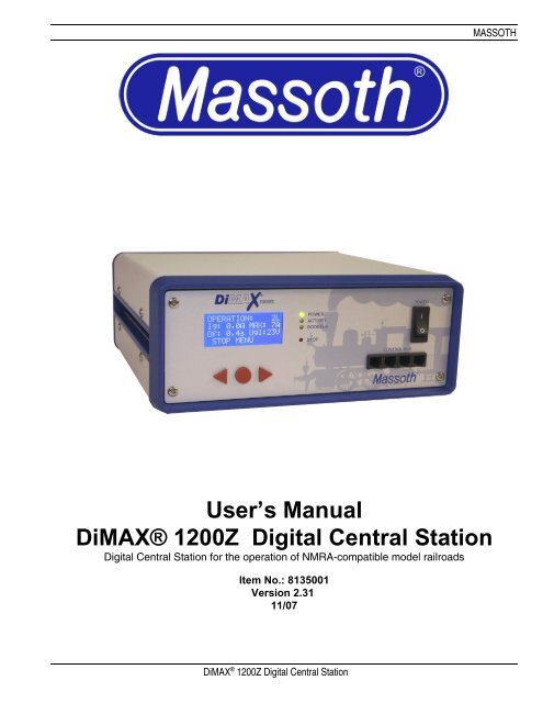
User’s Manual DiMAX® 1200Z Digital Central Station
User's Manual DiMAX® 1200Z Digital Central Station - Massoth
User's Manual DiMAX® 1200Z Digital Central Station - Massoth

You also want an ePaper? Increase the reach of your titles
YUMPU automatically turns print PDFs into web optimized ePapers that Google loves.
MASSOTH<br />
<strong>User’s</strong> <strong>Manual</strong><br />
<strong>DiMAX®</strong> <strong>1200Z</strong> <strong>Digital</strong> <strong>Central</strong> <strong>Station</strong><br />
<strong>Digital</strong> <strong>Central</strong> <strong>Station</strong> for the operation of NMRA-compatible model railroads<br />
Item No.: 8135001<br />
Version 2.31<br />
11/07<br />
DiMAX ® <strong>1200Z</strong> <strong>Digital</strong> <strong>Central</strong> <strong>Station</strong>
MASSOTH<br />
Index<br />
Page<br />
I. General Description 3<br />
II. Summary of Functions 3<br />
III. Layout of Terminals 4<br />
1 Please read this first! 4<br />
1.1 Safety Details and Warnings 4<br />
1.2 Warranties and Guaranties 5<br />
1.3 Warranty Claims 5<br />
1.4 Service and Customer Support 5<br />
2 Scope of Supply 5<br />
3 Introduction to <strong>Digital</strong> Control with <strong>DiMAX®</strong> <strong>Digital</strong> 6<br />
3.1 Database for 128 Locomotives 6<br />
3.2 Locomotive Address 6<br />
3.3 Speed Steps 6<br />
3.4 Producing Special Functions 7<br />
3.4.1 Producing Parallel Functions 7<br />
3.4.2 Producing Serial Functions 7<br />
3.5 Number of Locomotives in Simultaneous Operation 7<br />
4 Starting Up 8<br />
4.1 Connection 8<br />
4.2 Display and Keyboard 11<br />
4.3 Status LEDs 11<br />
4.4 Connecting the Input Devices 12<br />
4.5 Fuses 12<br />
5 The first switch-on 12<br />
5.1 The Display 13<br />
5.2 Menu Prompting 13<br />
5.3 The Emergency Stop Key 13<br />
6 Operational Settings 14<br />
6.1 Maximum Driving Current 14<br />
6.2 How to log off Locomotives when using the <strong>DiMAX®</strong> Transducer 15<br />
6.3 Turn Off Time in case of Short Circuit 15<br />
6.4 Maximum Number of Active Locomotives 15<br />
6.5 F-Functions beyond F8 16<br />
6.6 Track Voltage Adjustment 16<br />
7 Advanced System Settings 17<br />
DiMAX ® <strong>1200Z</strong> <strong>Digital</strong> <strong>Central</strong> <strong>Station</strong> 1
MASSOTH<br />
7.1 Settings of the Automatic Functions 17<br />
7.1.1 Save the Status of Active Locomotives 17<br />
7.1.2 Reset Status of Active Locomotives 18<br />
7.1.3 Store Automatic Functions 18<br />
7.1.4 Reset Automatic Functions 19<br />
7.1.5 Delete Locomotive Data Base 20<br />
7.2 System Settings 21<br />
7.2.1 Language 21<br />
7.2.2 Firmware Update 21<br />
7.2.3 System Information 21<br />
8 Menu Flow Chart 22<br />
9 Using LGB® MTS II Components with the <strong>DiMAX®</strong> <strong>Central</strong> <strong>Station</strong> 23<br />
9.1 Operating Mode of the <strong>DiMAX®</strong> 600A Transducer 23<br />
9.2 Managing Speed Steps in the <strong>DiMAX®</strong> 600A Transducer 23<br />
10 Advanced Functions 23<br />
10.1 Demonstration Mode 23<br />
10.2 Automatic Functions 24<br />
11 Software Update 25<br />
11.1 Connect your PC to the <strong>DiMAX®</strong> <strong>Central</strong> <strong>Station</strong> 25<br />
11.2 Update Program 26<br />
11.3 Software of <strong>DiMAX®</strong> Components 26<br />
11.4 Start Update Function of the <strong>DiMAX®</strong> <strong>Central</strong> <strong>Station</strong> 26<br />
11.5 Execute the Update 26<br />
12 Useful Hints 30<br />
12.1 The <strong>Central</strong> <strong>Station</strong> calls for a Software Update 30<br />
12.2 The <strong>Central</strong> <strong>Station</strong> cuts the Connection during Update 30<br />
12.3 Hidden Service Mode for Software Update of the <strong>Central</strong> <strong>Station</strong> 30<br />
12.4 Hidden Service Mode for Software Update of Bus Components 30<br />
12.5 How to Update the <strong>DiMAX®</strong> Navigator and other RC Components 30<br />
13 Glossary 31<br />
14 Support 34<br />
15 Manufacturer Information 34<br />
Please read this <strong>Manual</strong> thoroughly before operating your <strong>DiMAX®</strong> <strong>Central</strong> <strong>Station</strong><br />
DiMAX ® <strong>1200Z</strong> <strong>Digital</strong> <strong>Central</strong> <strong>Station</strong> 2
I. General Description<br />
MASSOTH<br />
The <strong>DiMAX®</strong> <strong>1200Z</strong> <strong>Central</strong> <strong>Station</strong> is the optimum choice for Garden Railroaders. It is the best combination<br />
of a powerful 12 Amps driving current, high safety standards and up to date high end technology.<br />
Based on the NMRA Standard the <strong>DiMAX®</strong> <strong>1200Z</strong> <strong>Central</strong> <strong>Station</strong> controls Locomotives equipped with decoders<br />
of all major manufacturers. A unique feature is the ability to produce digital and analog signals<br />
which enables the <strong>DiMAX®</strong> <strong>1200Z</strong> to operate locomotives equipped with older sound modules. A conversion<br />
of old models is therefore not necessary.<br />
II.<br />
Summary of Functions<br />
Properties of the <strong>DiMAX®</strong> <strong>1200Z</strong> <strong>Central</strong> <strong>Station</strong>:<br />
- Max 12 Amps Driving Current (adjustable to 4, 7 and 12 Amps)<br />
- Regular Supply Voltage 230V AC<br />
- Additional Supply Voltage 16 V to 24 V DC or 12 V to 18 V AC<br />
- Separate Programming Outlet<br />
- Voltage Limitation (Driving Voltage limited to 24 V DC)<br />
- Adjustable Turn Off Time in case of short circuit (between 0.1 and 0.8 sec)<br />
- Integrated Fan (Temperature Controlled)<br />
- LCD Display (White Letters with Blue Background Lighting)<br />
- Compatible to NMRA DCC<br />
- Compatible to LGB® MTS<br />
- Parallel and Serial Data Processing<br />
- Booster Interface<br />
- PC Interface (Protocol available for free)<br />
- Track Voltage Adjustment (only with new Hardware)<br />
System Properties:<br />
- 10239 Locomotive Addresses<br />
- 14/28/128 Speed Steps<br />
- 2048 Switch Addresses<br />
- 2048 Feed Back Addresses<br />
- Data Base of 128 Preconfigured Locomotives (Input with handheld Controller)<br />
- 32 Locomotives simultaneously controllable (other systems do 8 or 12 Locos)<br />
- Automatic Function without PC<br />
(using Feedback Interface and Train Detection Module)<br />
- Write CV (direct/indirect)<br />
- Read CV<br />
- Register Programming<br />
- PoM (Program on Main / Programming on Track)<br />
- LGB® MTS Components usable (via Transducer)<br />
- Automatic Speed Step Scaling (14/28/128) with LGB® Components<br />
DiMAX ® <strong>1200Z</strong> <strong>Digital</strong> <strong>Central</strong> <strong>Station</strong> 3
MASSOTH<br />
Note: The functional range of the <strong>DiMAX®</strong> <strong>1200Z</strong> <strong>Central</strong> <strong>Station</strong> is being updated on a<br />
regular basis. Suggestions are welcome. The <strong>DiMAX®</strong> <strong>1200Z</strong> <strong>Central</strong> <strong>Station</strong> can be easily kept up to<br />
date using the Update Function.<br />
III.<br />
Layout of Terminals<br />
- Mains (House Current/Outlet) Power Supply (230 V AC) separately fused<br />
- Additional External Power Supply (16 V to 24 V DC or 12 V to 18 V AC) separately fused<br />
- 4 Bus Outlets on the Front (e.g. for Handheld Controller)<br />
- 2 Bus Outlets on the Back (e.g. for Handheld Controller)<br />
- Track Power Terminal<br />
- Program Terminal<br />
- Booster Interface (on the back)<br />
- PC Interface RS232 (for Updates and PC-Controlling)<br />
Warning: The <strong>DiMAX®</strong> <strong>1200Z</strong> <strong>Central</strong> <strong>Station</strong> must never be connected to mains (House Current/Outlet)<br />
and an external power connection at the same time. This will result in major damage in the central station<br />
as well as other components.<br />
The bus outlets for handheld controllers, RC receivers, feedback modules etc. may be<br />
extended by an additional <strong>DiMAX®</strong> Adapter (Item No. 8138001).<br />
1 Please read this chapter thoroughly before starting the operation!<br />
1.1 Safety Details and Warnings<br />
1.1.1 This Product is not suitable for children under the age of 8 years. This product may have sharp edges. Inappropriate<br />
handling may cause injuries. Operate this product only with products posted in this manual. Measurements and<br />
electrical data are subject to change without further notice.<br />
1.1.2 The DiMAX is manufactured in compliance with FCC regulations. However it has no UL listing and no CSA registration.<br />
For this reason the <strong>1200Z</strong> may not be sold in the US, Canada and other countries using 110V/60Hz power.<br />
1.1.3 The <strong>DiMAX®</strong> <strong>1200Z</strong> <strong>Central</strong> <strong>Station</strong> may only be used for the operation of digitally controlled model railroads. Do<br />
never connect the bus connectors to your telephone line! This will result in irreparable and costly damages.<br />
1.1.4 The <strong>DiMAX®</strong> <strong>1200Z</strong> <strong>Central</strong> <strong>Station</strong> may only be operated with digital components posted in this manual. Even if<br />
other devices may have the same connectors, an operation will not be possible and may result in damage of the Di-<br />
MAX® <strong>1200Z</strong> <strong>Central</strong> <strong>Station</strong> and other components.<br />
1.1.5 Do not drop this product. Do not expose the <strong>DiMAX®</strong> <strong>1200Z</strong> <strong>Central</strong> <strong>Station</strong> to shocks and do not shake it. This<br />
may result in damage.<br />
1.1.6 Do not expose the <strong>DiMAX®</strong> <strong>1200Z</strong> <strong>Central</strong> <strong>Station</strong> to direct heat, sunlight or a damp environment. This may affect<br />
the operation.<br />
1.1.7 Do not open the <strong>DiMAX®</strong> <strong>1200Z</strong> <strong>Central</strong> <strong>Station</strong>. There are no user-serviceable components inside. This will void<br />
your warranty and may result in damage.<br />
1.1.8 Do not clean the <strong>DiMAX®</strong> <strong>1200Z</strong> <strong>Central</strong> <strong>Station</strong> with abrasive cleaners, strong acids or corrosive cleaners. Use a<br />
plastic-compatible cleaner or dry soft cloth only.<br />
1.1.9 We stress the fact that this product is not a toy. Do never leave your children unattended when operating the Di-<br />
MAX® <strong>1200Z</strong> <strong>Central</strong> <strong>Station</strong>. Children should operate this item only under supervision of adults.<br />
DiMAX ® <strong>1200Z</strong> <strong>Digital</strong> <strong>Central</strong> <strong>Station</strong> 4
MASSOTH<br />
1.1.10 Never use analog transformers on the same track with digital components. This goes for the operation of catenary<br />
lines also.<br />
1.1.11 Keep the ventilation grilles free of obstructions. These vents are needed for cooling the <strong>DiMAX®</strong> <strong>1200Z</strong><br />
<strong>Central</strong> <strong>Station</strong>. Do not pour any liquids into these grilles; keep the <strong>DiMAX®</strong> <strong>1200Z</strong> <strong>Central</strong> <strong>Station</strong> in a<br />
dry environment.<br />
1.1.12 Visually inspect your digital components regularly, remove damaged items immediately.<br />
1.1.13 The right to change this product in accordance with technical progress is reserved by MASSOTH<br />
ELEKTRONIK, Seeheim, Germany. We can not compensate for damages resulting from inappropriate<br />
handling, non-observance of this manual, operation with altered or damaged items or items not suitable<br />
for the <strong>DiMAX®</strong> <strong>1200Z</strong> <strong>Central</strong> <strong>Station</strong>. We do not compensate for damages resulting from overheating<br />
or moisture and inappropriate opening of the housing.<br />
1.1.14 Removing the safety label voids your warranty instantly and irrevocably.<br />
1.2 Warranties and Guaranties<br />
MASSOTH ELECTRONICS USA warrants this product for 1 year from the original date of purchase. This product is<br />
warranted against defects in materials and workmanship. Peripheral component damage is not covered by this warranty.<br />
Normal wear and tear, consumer modifications as well as inappropriate use and handling are not covered.<br />
Errors and changes excepted.<br />
1.3 Warranty Claims<br />
Valid warranty claims will be serviced without charge within the warranty period. To initiate a warranty claim, please<br />
contact your dealer or MASSOTH ELECTRONICS USA for an RMA (Return Merchandise Authorization). MAS-<br />
SOTH ELECTRONICS USA cannot be responsible for return shipping charges to our repair facility. Please include<br />
your Proof of Purchase with the returned goods.<br />
1.4 Service and Customer Support<br />
For support and technical questions contact: sales@massoth.com or call (see below).<br />
For downloading the latest firmware update go to www.massoth.com.<br />
Massoth Electronics USA, LLC<br />
6585 Remington Dr.<br />
Cumming, GA 30040<br />
Ph. 770-886-6670<br />
Fax 770-889-6837<br />
2 Scope of Supply<br />
• <strong>DiMAX®</strong> <strong>1200Z</strong> <strong>Central</strong> <strong>Station</strong><br />
• Power Cord (for the use in Germany, Switzerland, etc.)<br />
• Multi-Connector (to connect track power, programming track and external power source)<br />
• <strong>Manual</strong><br />
In case any of these items is missing or damaged contact your local dealer or the<br />
manufacturer.<br />
DiMAX ® <strong>1200Z</strong> <strong>Digital</strong> <strong>Central</strong> <strong>Station</strong> 5
MASSOTH<br />
Note: Please keep your box and the Styrofoam parts, to ensure proper packaging in case of shipping. If<br />
dropped, the <strong>DiMAX®</strong> <strong>1200Z</strong> <strong>Central</strong> <strong>Station</strong> can be damaged significantly.<br />
3 Introduction to <strong>Digital</strong> Control with <strong>DiMAX®</strong> <strong>Digital</strong><br />
The <strong>DiMAX®</strong> <strong>Digital</strong> System complies with the NMRA DCC Standard. All digital components that comply<br />
with this standard may be operated with the <strong>DiMAX®</strong> <strong>1200Z</strong> <strong>Central</strong> <strong>Station</strong>. The<br />
<strong>DiMAX®</strong> <strong>1200Z</strong> <strong>Central</strong> <strong>Station</strong> works with the special functions of the LGB® MTS System and NMRA<br />
compatible components on the same track.<br />
3.1 Database for 128 Locomotives<br />
One of the prominent benefits of the <strong>DiMAX®</strong> <strong>Digital</strong> System is the ability to store locomotive data permanently<br />
such as address, speed step configuration, special functions, and the pictogram. These data are<br />
made available to all <strong>DiMAX®</strong> Navigators or other handheld controllers connected to the <strong>DiMAX®</strong> <strong>Central</strong><br />
<strong>Station</strong>. This data is available after every power up and will not be lost after shut down. The names of the<br />
locomotives are generally user related and therefore stored in the handheld controller only.<br />
The integrated database stores up to 128 locomotives permanently. All relevant locomotive data is shown<br />
immediately after the respective address has been put in a <strong>DiMAX®</strong> Navigator. The address, speed steps,<br />
special functions, and pictogram are displayed here. The locomotive is ready to drive without any further<br />
actions. The only thing for you to do is: select and load the locomotive.<br />
3.2 Locomotive Address<br />
The <strong>DiMAX®</strong> <strong>Digital</strong> System identifies each locomotive by an address (Number 1…10239). The numbers<br />
1…9999 are used for regular locomotive addresses.<br />
3.3 Speed Steps<br />
The <strong>DiMAX®</strong> <strong>1200Z</strong> <strong>Central</strong> <strong>Station</strong> supports the usual 14, 28 and 128 speed steps defined by the NMRA<br />
DCC Standard. The speed steps define by which number the maximum driving current is divided. Using<br />
lower numbers result in a slow speed, the higher numbers result in faster speeds. A decoder programmed<br />
for 14 speed steps will control the locomotive in 14 voltage steps in every direction. 28 speed steps provide<br />
28 voltage steps, 128 speed steps 128 voltage steps respectively. For G-Scale Garden Railroading we recommend<br />
28 speed steps.<br />
In case no configuration of the locomotive has been done, the <strong>DiMAX®</strong> Navigator automatically configures<br />
the locomotive to 28 speed steps. Using LGB® Components in combination with a <strong>DiMAX®</strong> Transducer<br />
the locomotive will be controlled with 14 speed steps automatically.<br />
(See chapter 6 – LGB® MTS II Components with the <strong>DiMAX®</strong> <strong>1200Z</strong> <strong>Central</strong> <strong>Station</strong>)<br />
DiMAX ® <strong>1200Z</strong> <strong>Digital</strong> <strong>Central</strong> <strong>Station</strong> 6
MASSOTH<br />
Please note that in locos configured in 14 speed steps the light will not display correctly if they are controlled<br />
with 28 speed steps. The same is true for locos defined for 28 speed steps that are controlled with<br />
14 speed steps. In these cases the lights of the locomotives may flicker or may not work at all.<br />
3.4 Producing Special Functions<br />
The <strong>DiMAX®</strong> <strong>Digital</strong> System provides two kinds of function triggering: parallel and serial. The selection of<br />
the respective technique is made during the locomotive configuration via the<br />
<strong>DiMAX®</strong> Navigator or any other handheld controller.<br />
3.4.1 Producing Parallel Functions<br />
Parallel function triggering is standard in the NMRA DCC operation. Each function command is sent to the<br />
locomotive directly. Pushing the F1 key releases the function 1; the F2 key releases the function 2 and so<br />
on. The functions are produced immediately after pushing the key as there is only one single command to<br />
be sent to the locomotive.<br />
The number of functions has been changed during the last few years. It started out with 8 functions and<br />
was changed to 16 or more functions available. The <strong>DiMAX®</strong> <strong>Digital</strong> System is one of the few digital systems<br />
that support 16 functions according to the NMRA DCC Standard and the <strong>DiMAX®</strong> <strong>Digital</strong> System is<br />
ready to implement any further changes in the future.<br />
3.4.2 Producing Serial Functions<br />
Serial function triggering has a long story. Starting out as a single function triggered by one single key, the<br />
request for multiple functions resulted in the development of serial function triggering. As there was only<br />
one key available on the handheld controller, one had to push the same key repeatedly to get other functions.<br />
One had to push the key once for function #1, twice for function #2 and three times for function #3<br />
and so on. The F1 command was sent as a pulse string.<br />
Example 1:<br />
Example 2:<br />
The F1 key is pressed once and command #1 was sent once. Subsequently the<br />
whistle went off.<br />
The F1 key is pressed 5 times and the command was sent 5 times.<br />
Subsequently the function #5 was initiated.<br />
The higher the number of function, the more often the key had to be pushed. Therefore the delay between<br />
the command and the actual initiation depended on the value of the number of the command.<br />
Normally LGB® locomotives with serial sound function processing can be upgraded to parallel functions.<br />
3.5 Number of Locomotives in Simultaneous Operation<br />
The <strong>DiMAX®</strong> <strong>Digital</strong> System distinguishes between active and passive locomotives. Locomotives that are<br />
controlled by a <strong>DiMAX®</strong> Navigator or other handheld controller are active. Any command that is put into<br />
DiMAX ® <strong>1200Z</strong> <strong>Digital</strong> <strong>Central</strong> <strong>Station</strong> 7
MASSOTH<br />
the controller is transmitted to the <strong>DiMAX®</strong> <strong>1200Z</strong> <strong>Central</strong> <strong>Station</strong> and then sent to the locomotive.<br />
The maximum allowable number of active locomotives can be set in the <strong>DiMAX®</strong> <strong>1200Z</strong> <strong>Central</strong> <strong>Station</strong><br />
menu. The manufacturer’s setting is 16; a maximum of 32 locomotives is possible.<br />
It must be pointed out that the actual number of active locomotives, that receive data from the <strong>DiMAX®</strong><br />
<strong>1200Z</strong> <strong>Central</strong> <strong>Station</strong> actually slow down the system as the number grows because the <strong>Central</strong> <strong>Station</strong><br />
has to process the data and send these data to the locomotives. The <strong>DiMAX®</strong> <strong>1200Z</strong> <strong>Central</strong> <strong>Station</strong><br />
handles the active locomotives in strict rotation, once it is finished with the last one it starts all over with the<br />
first. Changes on the <strong>DiMAX®</strong> Navigator, e.g. input of F3, are sent to the track immediately. This happens<br />
in a fracture of a second. The more locomotives are there to be handled, the more data are to be processed.<br />
The Processing delay with 32 active locomotives may be up to 1.5 sec.<br />
A locomotive signed off while driving remains active. If a locomotive that is parked and not moving is signed<br />
off, it is not active anymore. The count of active locomotives is therefore reduced by the number of 1.<br />
Note: The data processing load per active locomotive is extensive. This is the reason for most of the digital<br />
systems to limit the number of active locomotives to 8 or a maximum of 12. The <strong>DiMAX®</strong> <strong>1200Z</strong> <strong>Central</strong><br />
<strong>Station</strong>s operate with two high performance processors that handle the data and the controlling of up<br />
to 32 active locomotives.<br />
4 Starting Up<br />
The chapters below will guide you through the set up and first operation of your <strong>DiMAX®</strong> <strong>1200Z</strong> <strong>Central</strong><br />
<strong>Station</strong>. Please follow every step closely.<br />
4.1 Connection<br />
Take your <strong>DiMAX®</strong> <strong>1200Z</strong> <strong>Central</strong> <strong>Station</strong> out of the box and position it in an appropriate place. The<br />
<strong>DiMAX®</strong> <strong>1200Z</strong> <strong>Central</strong> <strong>Station</strong> should not be placed close to a radiator, any other heater or in direct sunlight<br />
to ensure sufficient ventilation and temperature range for the <strong>DiMAX®</strong> <strong>1200Z</strong> <strong>Central</strong> <strong>Station</strong>.<br />
The ventilation outlet is on the back side and it should be kept clear of any<br />
obstructions at all times.<br />
DiMAX ® <strong>1200Z</strong> <strong>Digital</strong> <strong>Central</strong> <strong>Station</strong> 8
MASSOTH<br />
Illustration #1: Front view of the DiMAX <strong>1200Z</strong><br />
Illustration #2: Rear view of the DiMAX <strong>1200Z</strong><br />
Install the wires in the green multi connector, using a screwdriver, and plug it into the receptacle on the<br />
back side of the <strong>DiMAX®</strong> <strong>1200Z</strong> <strong>Central</strong> <strong>Station</strong>.<br />
DiMAX ® <strong>1200Z</strong> <strong>Digital</strong> <strong>Central</strong> <strong>Station</strong> 9
MASSOTH<br />
Illustration #3: Wiring diagram<br />
Important: Track power and program power must never be connected.<br />
Plug in the power cord on the back side and connect the <strong>DiMAX®</strong> <strong>1200Z</strong> <strong>Central</strong> <strong>Station</strong> to the house<br />
current. Switch on your <strong>DiMAX®</strong> <strong>1200Z</strong> <strong>Central</strong> <strong>Station</strong> using the main switch on the front side.<br />
Alternatively you may use an external power source (12V…18V AC or 16V…24V DC with approx. 350 VA).<br />
In this case the switch on the front panel is deactivated.<br />
Illustration #4: Power Connector, Fuse, PC<br />
Interface, Booster and 2 Bus Connectors<br />
DiMAX ® <strong>1200Z</strong> <strong>Digital</strong> <strong>Central</strong> <strong>Station</strong> 10
MASSOTH<br />
4.2 Display and Keyboard<br />
The display shows important information regarding the operation of your <strong>DiMAX®</strong> <strong>1200Z</strong><br />
<strong>Central</strong> <strong>Station</strong> at all times:<br />
Number of active locomotives, present current load (Amps), maximum Amps (12 Amps or as selected),<br />
turn off time in case of short circuit (as selected) and the measured driving voltage (24 V).<br />
Illustration #5: Display in driving mode<br />
Use the three keys below the display to navigate through the menu. The lower line in the display shows the<br />
assignments of the keys and the function respectively.<br />
4.3 Status LEDs<br />
4 LEDs show the state of operation of your <strong>DiMAX®</strong> <strong>1200Z</strong> <strong>Central</strong> <strong>Station</strong>:<br />
Power LED<br />
(green)<br />
Activity LED<br />
(yellow)<br />
Booster LED<br />
(yellow)<br />
Stop LED<br />
(red)<br />
After switch-on and after the successful internal test the <strong>DiMAX®</strong> <strong>1200Z</strong><br />
<strong>Central</strong> <strong>Station</strong> switches into normal<br />
driving mode. The power LED is steadily illuminated.<br />
The activity LED is blinking when data is being processed and sent to<br />
components. In case of software update this LED will blink during<br />
reception of data.<br />
The booster LED is illuminated if a booster is connected to the <strong>DiMAX®</strong><br />
<strong>1200Z</strong> <strong>Central</strong> <strong>Station</strong> and the data transfer between these components<br />
is working correctly.<br />
The STOP LED blinks or is illuminated if an emergency stop had been<br />
initiated by the <strong>DiMAX®</strong> <strong>1200Z</strong> <strong>Central</strong> <strong>Station</strong> or other components.<br />
DiMAX ® <strong>1200Z</strong> <strong>Digital</strong> <strong>Central</strong> <strong>Station</strong> 11
4.4 Connecting the Input Devices<br />
MASSOTH<br />
The <strong>DiMAX®</strong> <strong>1200Z</strong> <strong>Central</strong> <strong>Station</strong> features four receptacles for devices such as the <strong>DiMAX®</strong> Navigator<br />
and other <strong>DiMAX®</strong> Components such as the <strong>DiMAX®</strong> Feedback Interface, the<br />
<strong>DiMAX®</strong> Train Detection Module, a Switch Decoder or the <strong>DiMAX®</strong> Transducer for MTS II Bus Components.<br />
Two more receptacles are located on the back of the <strong>DiMAX®</strong> <strong>1200Z</strong> <strong>Central</strong> <strong>Station</strong> (See Illustr.<br />
#4).<br />
Illustration #6: Control Bus Receptacles and<br />
Power Switch<br />
After the completion of the internal system test the DiMAX <strong>1200Z</strong> will power up the control bus. Peripheral<br />
components connected to this bus will start working.<br />
4.5 Fuses<br />
The <strong>DiMAX®</strong> <strong>1200Z</strong> <strong>Central</strong> <strong>Station</strong> may be powered by the internal transformer or an external power<br />
source. The two power sources are separately fused. The fuses are accessible on the back side of your<br />
<strong>DiMAX®</strong> <strong>1200Z</strong> <strong>Central</strong> <strong>Station</strong>.<br />
The fuses for the 230V power are located in the socket beneath the receptacle. 2 fuses 250V/2.5A are<br />
used (See Illustr. #2).<br />
The external power is fused by a 12AT fuse located to the right of the 230V power socket (See Illustr. #2).<br />
5 First Switch-on<br />
After the switch-on the <strong>1200Z</strong> starts booting and displays three indications one after another. The last indication<br />
displays the serial number and the current software installed (Illustr. #7).<br />
Illustration #7: Indications during booting<br />
DiMAX ® <strong>1200Z</strong> <strong>Digital</strong> <strong>Central</strong> <strong>Station</strong> 12
MASSOTH<br />
5.1 The Display<br />
After booting the <strong>1200Z</strong> displays the main menu window for driving operation (Illustr. #8):<br />
Illustration #8: Driving operation<br />
5.2 Menu Prompting<br />
The settings of the digital system are accomplished in the menu of the <strong>1200Z</strong>. Several options are available.<br />
Open the menu by pressing the red round button marked “menu”. Use the three buttons to navigate<br />
through the menu to adjust the settings (Illustr. #9).<br />
5.3 The Emergency Stop Key<br />
Illustration #9: Menu Prompting<br />
There are several options to initiate an emergency stop. At the <strong>1200Z</strong> <strong>Central</strong> <strong>Station</strong> (Illustr. #10+11):<br />
Illustration #10: Emergency<br />
Stop<br />
Illustration #11: Cancel the<br />
emergency stop<br />
DiMAX ® <strong>1200Z</strong> <strong>Digital</strong> <strong>Central</strong> <strong>Station</strong> 13
MASSOTH<br />
The same functions are available with a DiMAX Navigator or the LGB Remote Control.<br />
6 Operational Settings (V2.30: new menu diagram)<br />
The set-up for the <strong>DiMAX®</strong> <strong>Digital</strong> System settings is accomplished in the <strong>Central</strong> <strong>Station</strong><br />
Menu. Several options are available.<br />
6.1 Maximum Driving Current<br />
The <strong>DiMAX®</strong><strong>1200Z</strong> <strong>Central</strong> <strong>Station</strong> provides the opportunity to limit the driving current on your layout. The<br />
<strong>DiMAX®</strong><strong>1200Z</strong> <strong>Central</strong> <strong>Station</strong> measures the current driving Amps and cuts off the power in case this limit<br />
is reached. The display of the <strong>1200Z</strong> as well as the display of the<br />
DiMAX Navigator show the prevailing driving current at all times.<br />
Illustration #12: Indication of the driving current in the<br />
<strong>1200Z</strong><br />
Illustration #13: Indication of the driving current in the<br />
Navigator<br />
The <strong>DiMAX®</strong><strong>1200Z</strong> <strong>Central</strong> <strong>Station</strong> delivers a maximum of 12 Amps. The adjustment steps are 4, 7,<br />
and 12 Amps. The keys to be pushed are shown inverted.<br />
Illustration #14: Selection of the driving current<br />
Adjust your driving current limit according to your actual current demand plus a little safety margin. The<br />
current demand of a single LGB® Locomotive may vary from 0.5 to 2 Amps depending on the number of<br />
motors and the configuration.<br />
Select the desired maximum current with the right hand key and leave the menu with the left hand key. After<br />
a few seconds the <strong>1200Z</strong> changes back to the driving operation window. Alternatively you may hit<br />
“NEXT” until the menu shows you this window.<br />
DiMAX ® <strong>1200Z</strong> <strong>Digital</strong> <strong>Central</strong> <strong>Station</strong> 14
6.2 How to log off Locomotives when using a <strong>DiMAX®</strong> Transducer<br />
MASSOTH<br />
Depending on the software version of the <strong>DiMAX®</strong> Transducer locomotives may be logged off as active or<br />
passive. Starting with version 1.2 of the <strong>DiMAX®</strong> Transducer the log off is active with older versions the log<br />
off type may be preset. It is advisable to utilize the active log off. (See 3.5)<br />
6.3 Turn Off Time in Case of Short Circuit<br />
This is a very important setting for Garden Railroaders. The <strong>DiMAX®</strong><strong>1200Z</strong> <strong>Central</strong> <strong>Station</strong> detects a short<br />
circuit and cuts off the power immediately with the Emergency Stop Function. After removal of the cause<br />
the normal operation may be reassumed.<br />
In digital operation reversing loop modules operate with short circuit detection. To prevent a power shut off,<br />
the shut off time can be adjusted. Depending on the design of a locomotive a short circuit may be triggered<br />
when passing a switch. Due to it's inertia and speed the locomotive slips by this critical location and drives<br />
on. During that time the driving current is limited to the maximum setting.<br />
A cutoff time setting between 0.1 and 0.8 sec is available per menu (Illustr. #15). The manufacturer’s setting<br />
is 0.4 sec as it proved to be the optimum setting.<br />
Illustration #15: Selection of the Turn Off Time<br />
Select the desired turn off time with the right hand key and leave the menu with the left hand key. After a<br />
few seconds the <strong>1200Z</strong> changes back to the driving operation window. Alternatively you may hit “NEXT”<br />
until the menu shows you this window.<br />
6.4 Maximum Number of Active Locomotives (available with V2.11 and on)<br />
This menu item limits the maximum number of active locomotives. The manufacturer’s setting is “16”. You<br />
may choose a number from 8 to 32. For further information referring active and passive locomotives<br />
see chapter 3.5.<br />
DiMAX ® <strong>1200Z</strong> <strong>Digital</strong> <strong>Central</strong> <strong>Station</strong> 15
MASSOTH<br />
Illustration #16: Selection of the Maximum Number of Active Locomotives<br />
Select the desired maximum number of active locomotives with the right hand key and leave the menu with<br />
the left hand key. After a few seconds the <strong>1200Z</strong> changes back to the driving operation window. Alternatively<br />
you may hit “NEXT” until the menu shows you this window.<br />
6.5 F-Functions beyond F8 (available with V2.30 and on)<br />
This setting switches off all functions greater than F8. This facilitates the operation of old generation decoders<br />
of other manufacturers (Illustr. #17).<br />
Illustration #17: Selection of F-Function Data<br />
Select the desired number of F-keys with the right hand key and leave the menu with the left hand key. After<br />
a few seconds the <strong>1200Z</strong> changes back to the driving operation window.<br />
Alternatively you may hit “NEXT” until the menu shows you this window.<br />
6.6 Track Voltage Adjustment (available with V2.30 and on)<br />
This menu facilitates the adjustment of the track voltage (Illustr. #18)<br />
Note: The track voltage adjustment is available only with the latest hardware and in operation with<br />
the internal transformer or an external AC power source.<br />
DiMAX ® <strong>1200Z</strong> <strong>Digital</strong> <strong>Central</strong> <strong>Station</strong> 16
MASSOTH<br />
Illustration #18: Selection track voltage adjustment<br />
Select the desired track voltage and leave the menu.<br />
7 Advanced System Settings<br />
The Advanced System Settings refer to the Advanced Functions as the Automatic Functions, the Demonstration<br />
Mode, and the Deletion of the Locomotive Data Base and the Update Function for the<br />
<strong>DiMAX®</strong><strong>1200Z</strong> <strong>Central</strong> <strong>Station</strong> and other digital components.<br />
7.1 Settings of the Automatic Functions<br />
7.1.1 Save the Status of Active Locomotives<br />
Use this menu item to save the status of your active locomotives, so your data do not get lost when you<br />
switch off your <strong>DiMAX®</strong><strong>1200Z</strong> <strong>Central</strong> <strong>Station</strong>. Your active locomotives will be reactivated after the next<br />
power up (Illustr. #19).<br />
Illustration #19: Selection of the Status of Active<br />
Locomotives<br />
After the selection the following window appears briefly (Illustr. #20):<br />
DiMAX ® <strong>1200Z</strong> <strong>Digital</strong> <strong>Central</strong> <strong>Station</strong> 17
MASSOTH<br />
Having saved the setting you may leave the menu with the left hand key.<br />
After a few seconds the <strong>1200Z</strong> changes back to the driving operation window.<br />
Alternatively you may hit “NEXT” until the menu shows you this window.<br />
7.1.2 Reset Status of Active Locomotives<br />
Illustration #20: Saving the<br />
setting<br />
In case you do not want to reactivate your stored active locomotives, you may use the reset function in the<br />
menu. The active locomotive data will be lost thereafter (Illustr. #21).<br />
Illustration #21: Selection “Reset operating conditions of active locos”<br />
After the selection the following window appears briefly (Illustr. #22):<br />
Illustration #22: Saving the<br />
setting<br />
Having saved the setting you may leave the menu with the left hand key.<br />
After a few seconds the <strong>1200Z</strong> changes back to the driving operation window.<br />
Alternatively you may hit “NEXT” until the menu shows you this window.<br />
7.1.3 Store Automatic Functions (available with V2.20 and on)<br />
Store your automatic functions with this menu item. After restarting your <strong>DiMAX®</strong><strong>1200Z</strong> <strong>Central</strong> <strong>Station</strong> all<br />
automatic functions will be available right away, all contacts with the respective functions will be included in<br />
the operation again; e.g. the reversing loop is functional immediately (Illustr. #23).<br />
DiMAX ® <strong>1200Z</strong> <strong>Digital</strong> <strong>Central</strong> <strong>Station</strong> 18
MASSOTH<br />
Illustration #23: Selection “Save Automatic Functions”<br />
After the selection the following window appears briefly (Illustr. #24):<br />
Illustration #24: Saving the<br />
setting<br />
Having saved the setting you may leave the menu with the left hand key.<br />
After a few seconds the <strong>1200Z</strong> changes back to the driving operation window.<br />
Alternatively you may hit “NEXT” until the menu shows you this window.<br />
7.1.4 Reset Automatic Functions (available with V2.20 and on)<br />
All stored automatic functions are kept in the <strong>1200Z</strong> and will be activated every time the central station is<br />
switched on. This menu item reset all stored automatic functions (Illustr. #25).<br />
Illustration #25: Selection “Reset Automatic Functions”<br />
After the selection the following window appears briefly (Illustr. #26):<br />
DiMAX ® <strong>1200Z</strong> <strong>Digital</strong> <strong>Central</strong> <strong>Station</strong> 19
MASSOTH<br />
Having saved the setting you may leave the menu with the left hand key.<br />
After a few seconds the <strong>1200Z</strong> changes back to the driving operation window.<br />
Alternatively you may hit “NEXT” until the menu shows you this window.<br />
7.1.5 Delete Locomotive Data Base (takes 30 sec)<br />
Illustration #26: Saving the<br />
setting<br />
Delete all saved locomotive data. The data base will be empty as in the delivery status. Deleting takes<br />
about 30 seconds, do not switch off your <strong>DiMAX®</strong><strong>1200Z</strong> <strong>Central</strong> <strong>Station</strong> during this action.<br />
The central station will restart thereafter (Illustr. #27).<br />
Illustration #27: Selection “Delete Loco Data Base”<br />
After the selection the following window appears briefly (Illustr. #28):<br />
Illustration #28: Saving the<br />
setting<br />
The <strong>1200Z</strong> will restart after saving.<br />
DiMAX ® <strong>1200Z</strong> <strong>Digital</strong> <strong>Central</strong> <strong>Station</strong> 20
MASSOTH<br />
7.2 System Settings<br />
7.2.1 Language (available with V2.11 and on)<br />
Choose the language of your display with this menu item. Options: English/German (Illustr. #29)<br />
Illustration #29: Language selection<br />
Select the desired language with the right hand key and leave the menu with the left hand key. After a few<br />
seconds the <strong>1200Z</strong> changes back to the driving operation window.<br />
Alternatively you may hit “NEXT” until the menu shows you this window.<br />
7.2.2 Firmware Update<br />
The <strong>DiMAX®</strong><strong>1200Z</strong> <strong>Central</strong> <strong>Station</strong> provides this function to update the software of the <strong>DiMAX®</strong><strong>1200Z</strong><br />
<strong>Central</strong> <strong>Station</strong> or other <strong>DiMAX®</strong> components.<br />
Find a detailed description of the update procedure in chapter 10.<br />
7.2.3 System Information (available with V2.30 and on)<br />
This menu item provides additional system information, e.g. system temperature,<br />
memory usage of the loco data base and the automatic functions (Illustr. #30).<br />
Illustration #30: Selection “System Information”<br />
Hit the left hand key to leave the menu. After a few seconds the <strong>1200Z</strong> changes back to the<br />
driving operation window. Alternatively you may hit “NEXT” until the menu shows you this window.<br />
DiMAX ® <strong>1200Z</strong> <strong>Digital</strong> <strong>Central</strong> <strong>Station</strong> 21
MASSOTH<br />
8 Menu Flow Chart<br />
DiMAX ® <strong>1200Z</strong> <strong>Digital</strong> <strong>Central</strong> <strong>Station</strong> 22
9 Using LGB® MTS II Components with the <strong>DiMAX®</strong><strong>1200Z</strong> <strong>Central</strong> <strong>Station</strong><br />
MASSOTH<br />
Your <strong>DiMAX®</strong><strong>1200Z</strong> <strong>Central</strong> <strong>Station</strong> may be used with all <strong>DiMAX®</strong> Components of the <strong>DiMAX®</strong> Series, e.<br />
g. the <strong>DiMAX®</strong> Navigator, and in addition with all LGB® MTS II Components using a <strong>DiMAX®</strong> 600A Transducer<br />
(Item 8138501). The <strong>DiMAX®</strong> 600A Transducer translates the LGB® MTS II data into <strong>DiMAX®</strong> compliant<br />
bus data to ensure the operation of LGB® MTS II Components e.g. feedback modules and others.<br />
9.1 Operating Mode of the <strong>DiMAX®</strong> 600A Transducer<br />
The <strong>DiMAX®</strong> 600A Transducer converts the LGB® MTS II Bus Data into <strong>DiMAX®</strong> Bus Data. The<br />
<strong>DiMAX®</strong><strong>1200Z</strong> <strong>Central</strong> <strong>Station</strong> and the <strong>DiMAX®</strong> 600A Transducer are communicating with each other and<br />
produce, depending on the data stored in the <strong>DiMAX®</strong><strong>1200Z</strong> <strong>Central</strong> <strong>Station</strong>, the driving commands according<br />
to the speed steps set. The DiMAX 600A Transducer requires an external power source (e.g. LGB<br />
transformer).<br />
9.2 Managing Speed Steps in the <strong>DiMAX®</strong> 600A Transducer (avail. with V2.20 and on)<br />
The LGB® MTS II works with 14 speed steps only as is known. The <strong>DiMAX®</strong> 600A Transducer enables<br />
you to control locomotives with more than 14 speed steps. It is able to scale the speed steps to ensure an<br />
operation of a LGB Loco Remote in connection with the <strong>DiMAX®</strong><strong>1200Z</strong> <strong>Central</strong> <strong>Station</strong>. This means you<br />
can operate your locomotive with 28 speed steps even with the LGB® Loco Remote. Please note that the<br />
locomotive operated must be configured with a <strong>DiMAX®</strong> Navigator and stored in the data base of the<br />
<strong>DiMAX®</strong> <strong>1200Z</strong> <strong>Central</strong> <strong>Station</strong>. In case the locomotive is not stored it will be operated with 14 speed steps<br />
only.<br />
10 Advanced Functions<br />
The <strong>DiMAX®</strong><strong>1200Z</strong> <strong>Central</strong> <strong>Station</strong> features Special Functions only a few others can offer. Highlights are<br />
the Demonstration Mode, the Automatic Functions, and Controlling by PC.<br />
10.1 Demonstration Mode<br />
The <strong>DiMAX®</strong><strong>1200Z</strong> <strong>Central</strong> <strong>Station</strong> features a special mode for automatic demonstration. To utilize this<br />
feature you have to store all active locomotives that are stored while running and switch off the<br />
<strong>DiMAX®</strong><strong>1200Z</strong> <strong>Central</strong> <strong>Station</strong> subsequently. When the <strong>DiMAX®</strong><strong>1200Z</strong> <strong>Central</strong> <strong>Station</strong> is switched on<br />
again all data are being loaded and all locomotives that were previously running will start running again automatically.<br />
There is no need to start every locomotive individually.<br />
DiMAX ® <strong>1200Z</strong> <strong>Digital</strong> <strong>Central</strong> <strong>Station</strong> 23
MASSOTH<br />
Save Operating Condition of Active Locomotives<br />
Push the “SEL.” Button and switch off the <strong>DiMAX®</strong><strong>1200Z</strong> <strong>Central</strong> <strong>Station</strong>. After the next power up all locomotives<br />
that were previously running will start running again assuming their last assigned speed.<br />
To deactivate this function simply reset the data of the active locomotives:<br />
Reset Status of Active Locomotives<br />
Illustration #31: Selection of the Status of Active<br />
Locomotives<br />
Illustration #32: Selection “Reset operating conditions of active locos”<br />
Note: The <strong>1200Z</strong> uses the data of the active locomotives (See 4.5) and stores these data separately.<br />
10.2 Automatic Functions (available with V2.20 and on)<br />
The <strong>DiMAX®</strong><strong>1200Z</strong> <strong>Central</strong> <strong>Station</strong> features the ability to utilize simple automatic functions without making<br />
use of a PC. You may control the driving direction and switches directly for example. To capture the desired<br />
time of change in the driving direction a feedback module must be used. You may use a <strong>DiMAX®</strong><br />
Feedback Module (Item No. 8170001), a <strong>DiMAX®</strong> Train Detection Module (Item No. 8170501) or in conjunction<br />
with a <strong>DiMAX®</strong> 600A Transducer a LGB® Feedback Module (Item No. 55070) or a LGB® Train<br />
Detection Module (Item No. 55075). In case you use a feedback module you will need reed switches (e.g.<br />
LGB® Item No. 17100) and LGB® EPL Loco Magnets.<br />
You may define a total of 32 automatic functions and run up to 8 trains automatically.<br />
Programming is carried out with a <strong>DiMAX®</strong> Navigator.<br />
The store function enables you to store your automatic functions in the <strong>DiMAX®</strong><strong>1200Z</strong> <strong>Central</strong> <strong>Station</strong> so<br />
that they are available after the next power up of the station.<br />
DiMAX ® <strong>1200Z</strong> <strong>Digital</strong> <strong>Central</strong> <strong>Station</strong> 24
MASSOTH<br />
Storing Automatic Functions:<br />
Illustration #33: Selection “Save Automatic Functions”<br />
Reset Automatic Functions:<br />
Illustration #34: Selection “Reset Automatic Functions”<br />
Note: Please find the detailed description of the programming procedure in the<br />
<strong>DiMAX®</strong> Navigator <strong>Manual</strong>.<br />
11 Softwareupdate<br />
The <strong>DiMAX®</strong><strong>1200Z</strong> <strong>Central</strong> <strong>Station</strong> and connected <strong>DiMAX®</strong> Components may be updated with the latest<br />
firmware available at any given time. The chapter below describes the steps to be followed.<br />
11.1 Connect your PC to the <strong>DiMAX®</strong><strong>1200Z</strong> <strong>Central</strong> <strong>Station</strong><br />
Your PC must be connected to the <strong>DiMAX®</strong><strong>1200Z</strong> <strong>Central</strong> <strong>Station</strong> to provide a communication between<br />
these two units. The connection is arranged by using a standard serial communication cable. For safety reasons<br />
make sure that only those components which are to be updated are connected to the <strong>DiMAX®</strong><br />
<strong>1200Z</strong> <strong>Central</strong> <strong>Station</strong>.<br />
Note: Do not use a 0-modem cable as this does not provide a suitable connection.<br />
DiMAX ® <strong>1200Z</strong> <strong>Digital</strong> <strong>Central</strong> <strong>Station</strong> 25
MASSOTH<br />
11.2 Update Program<br />
The update is accomplished by the “<strong>DiMAX®</strong> Update” program which is available for download on<br />
www.massoth.com for free. Please find the download page in the section “Support & Download” subsection<br />
“Software resp. Firmware”. We recommend saving this program in a separate folder e.g. C:\DiMAX. The<br />
update program supports automatic language recognition and will welcome you in English or German.<br />
11.3 Software of <strong>DiMAX®</strong> Components<br />
The download site mentioned above also provides you with the update files for your <strong>DiMAX®</strong> <strong>1200Z</strong> <strong>Central</strong><br />
<strong>Station</strong> and other <strong>DiMAX®</strong> Components. It is convenient to save the update files in your DiMAX folder.<br />
All update files are easily recognizable as they end with “.dimax”.<br />
11.4 Start the Update Function of the <strong>DiMAX®</strong> <strong>1200Z</strong> <strong>Central</strong> <strong>Station</strong><br />
To start an update of the <strong>DiMAX®</strong> <strong>1200Z</strong> <strong>Central</strong> <strong>Station</strong> or any other DiMAX component, select the update<br />
function in the menu (Illustr. #35).<br />
Illustration #35: Selection Firmware Update<br />
The boot loader of the <strong>DiMAX®</strong> <strong>1200Z</strong> <strong>Central</strong> <strong>Station</strong> starts and waits for the update file to be transmitted<br />
from the PC.<br />
11.5 Execute the Update<br />
Having the <strong>DiMAX®</strong> <strong>1200Z</strong> <strong>Central</strong> <strong>Station</strong> ready for reception (Steps 11.1 to 11.4.) you now start the Di-<br />
MAX® Update Program on your PC: “DiMAX_Update.exe”.<br />
The program opens with the following page:<br />
DiMAX ® <strong>1200Z</strong> <strong>Digital</strong> <strong>Central</strong> <strong>Station</strong> 26
MASSOTH<br />
Confirm the start page with “Next”<br />
This page requests the selection of the update file for the DiMAX component to be updated. Click “Browse”<br />
to search for the respective update file.<br />
In case the file has been saved in the same folder as described in 11.3, the file is to be found in: C:\DI-<br />
MAX.<br />
DiMAX ® <strong>1200Z</strong> <strong>Digital</strong> <strong>Central</strong> <strong>Station</strong> 27
MASSOTH<br />
A selection window opens. Open the folder that contains the update file, e.g. C:\DiMAX and select the required<br />
update file by clicking “open”. The names of the files are defined by the Massoth Item No. and the software version.<br />
Select the com port used with your com cable and acknowledge with “Next”<br />
Note: The com address (COM1, COM2, etc.) depends on the specifications of the PC used, the number<br />
of com ports available, and the peripheral equipment used (e.g. USB-Adapter).<br />
DiMAX ® <strong>1200Z</strong> <strong>Digital</strong> <strong>Central</strong> <strong>Station</strong> 28
MASSOTH<br />
The program shows the relevant data of the upcoming update: Firmware Version and <strong>DiMAX®</strong> Component<br />
to be updated. A security check makes sure the <strong>DiMAX®</strong> <strong>1200Z</strong> <strong>Central</strong> <strong>Station</strong> is ready for reception.<br />
Click “NEXT”.<br />
The update procedure starts and the progress is shown with a progress bar. After the update the program<br />
confirms the successful update and closes automatically. If the <strong>DiMAX®</strong> <strong>1200Z</strong><br />
<strong>Central</strong> <strong>Station</strong> was updated the unit restarts and shows the new software version during the restart.<br />
In case you update a <strong>DiMAX®</strong> Component, e.g. the <strong>DiMAX®</strong> Navigator, make sure that only the component<br />
to be updated is connected to the <strong>DiMAX®</strong> <strong>1200Z</strong> <strong>Central</strong> <strong>Station</strong>.<br />
DiMAX ® <strong>1200Z</strong> <strong>Digital</strong> <strong>Central</strong> <strong>Station</strong> 29
12 Useful Hints<br />
MASSOTH<br />
12.1 The <strong>DiMAX®</strong> <strong>1200Z</strong> <strong>Central</strong> <strong>Station</strong> calls for a Software Update<br />
This message appears if an update was not carried out successfully or was interrupted. The <strong>DiMAX®</strong><br />
<strong>1200Z</strong> <strong>Central</strong> <strong>Station</strong> starts automatically in the update mode and waits for an update. Perform a new update<br />
as described in chapter 11.<br />
12.2 The <strong>DiMAX®</strong> <strong>1200Z</strong> <strong>Central</strong> <strong>Station</strong> cuts the Connection during Update<br />
In case the <strong>DiMAX®</strong> <strong>1200Z</strong> <strong>Central</strong> <strong>Station</strong> repeatedly cuts the connection during updating, you must use<br />
a hidden service function to start the <strong>DiMAX®</strong> <strong>1200Z</strong> <strong>Central</strong> <strong>Station</strong> directly in the update mode. This<br />
function is to be used if a regular update is not possible.<br />
12.3 Hidden Service Mode for Software Update of the <strong>DiMAX®</strong> <strong>1200Z</strong> <strong>Central</strong> <strong>Station</strong><br />
(available with V2.12 and on)<br />
Keep the round red button pushed while switching on the <strong>DiMAX®</strong> <strong>1200Z</strong> <strong>Central</strong> <strong>Station</strong>. The <strong>DiMAX®</strong><br />
<strong>1200Z</strong> <strong>Central</strong> <strong>Station</strong> will report faulty software and start the boot loader. Now the <strong>DiMAX®</strong> <strong>1200Z</strong> <strong>Central</strong><br />
<strong>Station</strong> waits for data to be transmitted from your PC.<br />
Note: This service mode only works for the <strong>DiMAX®</strong> <strong>1200Z</strong> <strong>Central</strong> <strong>Station</strong> as only the core of the <strong>Central</strong><br />
<strong>Station</strong> is working; the data bus to the components is disconnected.<br />
12.4 Hidden Service Mode for Software Update of Bus Components<br />
From version V 2.3 on the <strong>DiMAX®</strong> <strong>1200Z</strong> <strong>Central</strong> <strong>Station</strong> features an additional hidden service mode for<br />
the update of <strong>DiMAX®</strong> Bus Components:<br />
Keep the right hand key of your <strong>DiMAX®</strong> <strong>1200Z</strong> <strong>Central</strong> <strong>Station</strong> pushed while switching on the <strong>Central</strong> <strong>Station</strong>.<br />
The <strong>DiMAX®</strong> <strong>1200Z</strong> <strong>Central</strong> <strong>Station</strong> initializes the control bus and starts the update mode automatically.<br />
12.5 How to Update the <strong>DiMAX®</strong> Navigator and other RC Components (Available with V2.30 and on)<br />
Please note that components having a RC connection can only be updated when connected to the<br />
<strong>DiMAX®</strong> <strong>1200Z</strong> <strong>Central</strong> <strong>Station</strong> by cable. The <strong>DiMAX®</strong> Navigator must be switched off and connected to<br />
the <strong>DiMAX®</strong> <strong>1200Z</strong> <strong>Central</strong> <strong>Station</strong> by cable to conduct the update. After being connected by cable the Di-<br />
MAX® Navigator starts automatically, no further settings are necessary.<br />
DiMAX ® <strong>1200Z</strong> <strong>Digital</strong> <strong>Central</strong> <strong>Station</strong> 30
MASSOTH<br />
13 GLOSSARY<br />
●<br />
●<br />
●<br />
●<br />
●<br />
●<br />
●<br />
●<br />
●<br />
Bit<br />
Bit is short for binary digit the smallest unit of data in a computer taking a value of either “0” or “1”. 8 bit<br />
sum up to one byte.<br />
Booster<br />
A booster is an amplifier in a DCC system to add additional track power to the layout.<br />
Bus / Bus system<br />
A bus system is the electrical connection between control components of a DCC system. The various<br />
bus systems being currently utilized by different manufacturers are basically not compatible.<br />
Byte<br />
A byte is a contiguous sequence of a fixed number of bits, normally eight. The decimal value of a byte<br />
varies between “0” and “255”.<br />
<strong>Central</strong> <strong>Station</strong><br />
The central station is the brain of a digital system. All commands, feedbacks, etc, are processed here<br />
and then transferred to the respective components; either via an integrated booster to the track or by a<br />
bus line to an additional booster.<br />
CV - Configuration variable<br />
In DCC decoders various settings, so-called CVs, may be defined. A CV consists of a byte (= 8 bit) and<br />
may have a value between “0” and “255”.<br />
CV-Programming, Direct CV Programming, Direct Mode (DM)<br />
The CV setting may be changed by CV programming. Programming can be done bit-by-bit ( one of the<br />
eight bits is altered) or in bytes (the whole byte - means all 8 bit - will be altered). The system allows a<br />
read-out of CVs as well.<br />
DCC<br />
DCC is the abbreviation for <strong>Digital</strong> Command Control. It is a standardized model railroad digital system.<br />
Another system is e.g. Motorola. The central station and the decoders must operate under the same<br />
system.<br />
Decoder<br />
A decoder (switch decoder, loco decoder) converts the commands of the central station into the<br />
respective action (e.g. operate a switch, drive a motor).<br />
DiMAX ® <strong>1200Z</strong> <strong>Digital</strong> <strong>Central</strong> <strong>Station</strong> 31
MASSOTH<br />
●<br />
●<br />
●<br />
●<br />
●<br />
●<br />
●<br />
●<br />
●<br />
<strong>Digital</strong> System<br />
A digital system is an electronic control system for multiple train operation on the same track. In addition<br />
to the driving current commands for driving speed, deceleration, as well as functions e.g. light on/ light<br />
off can be transferred via the track to the locomotives. Every locomotive / car needs to have an<br />
individual digital address and they must be equipped with digital decoders.<br />
Currently various protocols are used but cannot be mixed.<br />
<strong>Digital</strong> Address<br />
In a digital system each loco/car or component like switches or signals need an individual address<br />
which consists of numbers. The number of addresses varies with the digital system used, some contain<br />
only 256 addresses, and the Massoth system contains 10239 addresses.<br />
Interface<br />
Basically an interface is the connecting component between a digital system and a computer. In case a<br />
computer has to control a model railroad layout an interface is necessary to control the various<br />
modules. In many digital systems an interface is already implemented.<br />
MOROP<br />
MOROP is the Federation of the European Model Railroaders,founded 1954 and based in Bern,<br />
Switzerland. The intention of this federation is among other things to establish the European norm of<br />
model railroading (NEM). A work group was established to adjust the rules and regulations of the NEM<br />
to the latest changes in technology.<br />
MTS<br />
MTS stands for Multi Train System and is the digital system of LGB. This system works according to the<br />
DCC standards of NMRA.<br />
NEM<br />
NEM is the European norm for model railroads. This norm is to ensure a uniform standard of couplers,<br />
tracks, switches, digital decoders and other components in the world of model railroading. Even the<br />
different eras of model railroading are established in the NEM.<br />
NMRA<br />
NMRA=National Model Railroader Association. The NMRA sets standards for DCC systems on the<br />
American market.<br />
POM (Programming on the Main)<br />
PoM is the name for one of the latest procedures of programming locomotives on the main layout track<br />
during normal operation.<br />
Protocol<br />
A protocol is a systematical arrangement in which digital commands are organized.<br />
DiMAX ® <strong>1200Z</strong> <strong>Digital</strong> <strong>Central</strong> <strong>Station</strong> 32
MASSOTH<br />
●<br />
Speed Steps<br />
The maximum power of a motor is divided into speed steps. Each speed step may be addressed<br />
individually. The driving characteristics get smoother with the increasing number of speed steps.<br />
DiMAX ® <strong>1200Z</strong> <strong>Digital</strong> <strong>Central</strong> <strong>Station</strong> 33
14 Support<br />
MASSOTH<br />
For support and service contact your dealer or the US Branch of the manufacturer. The manufacturer’s<br />
web site provides you with the latest information and documentation concerning your product. A helpful list<br />
of FAQs is provided. In addition the web site contains the latest firmware versions for download. For technical<br />
questions contact<br />
hotline@massoth.de or<br />
sales@massoth.com.<br />
15 Manufacturer Information<br />
Massoth Elektronik GmbH<br />
Frankensteiner Strasse 28<br />
64342 Seeheim-Malchen<br />
- GERMANY -<br />
Ph. 011-49-6151-35077-0<br />
Fax 011-49-6151-35077-44<br />
Massoth Electronics USA<br />
6585 Remington Dr. Suite 200<br />
Cumming, GA 30040<br />
Ph. 770-886-6670<br />
Fax 770-889-6837<br />
Cell 850-218-0709<br />
sales@massoth.com<br />
Massoth ® and DiMAX ® are registered trademarks by Massoth Elektronik GmbH, Seeheim, Germany. LGB ® is a registered trademark and property of its respective owner. All other<br />
trademarks printed are registered trademarks as well. No parts of this work may be reproduced or transmitted in any form or by any means, electronic or mechanical, including photocopying<br />
and recording, or by any information storage or retrieval system without the prior written permission by Massoth Elektronik GmbH unless such copying is expressly permitted<br />
by federal copyright law.<br />
11/07 TI<br />
DiMAX ® <strong>1200Z</strong> <strong>Digital</strong> <strong>Central</strong> <strong>Station</strong> 34