AnsaldoEnergia
AnsaldoEnergia - KIT
AnsaldoEnergia - KIT
- No tags were found...

You also want an ePaper? Increase the reach of your titles
YUMPU automatically turns print PDFs into web optimized ePapers that Google loves.
Divisione Nucleare<br />
Progetto<br />
Project<br />
PDS-XADS<br />
<strong>AnsaldoEnergia</strong><br />
Identificativo<br />
Document no.<br />
XADS 20 TRIX 009<br />
Rev.<br />
Rev.<br />
1<br />
Cl. ris.<br />
class<br />
Pagina<br />
Page<br />
47<br />
Event [2.2] refers to anomalies in the Target Unit Coolant System pressure and temperature<br />
variation originate from malfunctions or failures of systems and components normally<br />
devoted to (directly or indirectly) control the TUCS pressure or temperature.<br />
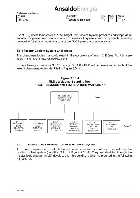
3.5.1 Reactor Coolant System Challenges<br />
The phenomenologies that could result in the occurrence of event [2.1] (see Fig 3.3-1) are<br />
listed in the level 3 MLD of the Fig. 3.5.1-1.<br />
In the following subsections 3.5.1.1 through 3.5.1.6 a MLD will be developed for each of the<br />
level 3 phenomenologies identified in Figure 3.5.1-1.<br />
Figure 3.5.1-1<br />
MLD development starting from<br />
" RCS PRESSURE and TEMPERATURE VARIATION "<br />
[2.1]<br />
RCS PRESSURE or<br />
TEMPERATURE<br />
VARIATION<br />
level 2<br />
[2.1.1]<br />
INCREASE in<br />
HEAT<br />
REMOVAL<br />
from RCS<br />
[2.1.2]<br />
DECREASE in<br />
HEAT<br />
REMOVAL<br />
from RCS<br />
[2.1.3]<br />
DECREASE in<br />
PRIMARY<br />
COOLANT<br />
FLOWRATE<br />
[2.1.4]<br />
INCREASE in<br />
PRIMARY<br />
COOLANT<br />
FLOWRATE<br />
[2.1.5]<br />
DECREASE of<br />
PRIMARY<br />
Pb-Bi<br />
INVENTORY<br />
[2.1.6]<br />
INCREASE of<br />
RCS<br />
PRESSURE<br />
level 3<br />
3.5.1.1 Increase in Heat Removal from Reactor Coolant System<br />
There are a number of events that could result in an increase of heat removal from the<br />
reactor coolant system (condition 2.1.1 of Figure 3.5.1-1). They are identified through the<br />
master logic diagram (MLD) developed for this condition, which is reported in the following<br />
Fig. 3.5.1-2.<br />
DNU 020/1