Conveying with ease Fitting and operational manual Declaration of ...
Conveying with ease Fitting and operational manual Declaration of ...
Conveying with ease Fitting and operational manual Declaration of ...

Create successful ePaper yourself
Turn your PDF publications into a flip-book with our unique Google optimized e-Paper software.
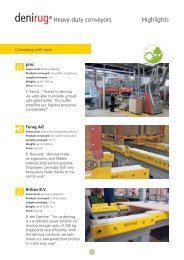
<strong>Conveying</strong> <strong>with</strong> <strong>ease</strong><br />
deniroll ® curve support<br />
<strong>Fitting</strong> <strong>and</strong> <strong>operational</strong> <strong>manual</strong><br />
<strong>Declaration</strong> <strong>of</strong> incorporation
Contents<br />
Page<br />
1 General ··································································· 2<br />
2 Safety ······································································ 3<br />
2.1 Proper usage ··························································· 3<br />
2.2 General safety instructions ······································· 3<br />
2.3 Operational conditions ············································· 3<br />
3 Outline ···································································· 4<br />
3.1 Principle/structure ···················································· 4<br />
3.2 Main body/technical details ····································· 4<br />
3.3 Types/included <strong>with</strong> product ···································· 4<br />
3.4 Storage ··································································· 5<br />
4 Assembly ································································· 6<br />
4.1 Assembly instructions ·············································· 6<br />
4.2 Assembly tolerances ················································ 6<br />
4.3 Retr<strong>of</strong>i tting procedure ············································· 7<br />
1 General<br />
All these instructions have been drawn up exclusively by<br />
assembly, <strong>operational</strong> <strong>and</strong> maintenance personnel that are<br />
technically qualifi ed. Pl<strong>ease</strong> read these instructions carefully<br />
before fi tting the deniroll ® curve support <strong>and</strong> commissioning<br />
the conveyor in question. This document includes safety<br />
instructions.<br />
The specifi cations in the order confi rmation list the exact<br />
technical data on the deniroll ® curve support you have been<br />
supplied <strong>with</strong>.<br />
The assembly <strong>of</strong> the deniroll ® curve support is the same for<br />
all conveying angles <strong>and</strong> widths. The size shown in the fi gures<br />
(curve angle 90°) was only selected to make the drawing<br />
easier to underst<strong>and</strong>.<br />
5 Operation ································································ 8<br />
5.1 Commissioning/recommissioning ····························· 8<br />
5.2 Shutting down ························································ 8<br />
5.3 Disposal ··································································· 8<br />
6 Maintenance/cleaning ············································· 8<br />
6.1 Maintenance ··························································· 8<br />
6.2 Cleaning ·································································· 8<br />
7 Repair ······································································ 9<br />
7.1 Exchanging the roller belt in curve supports<br />
<strong>with</strong> insertion opening ············································· 9<br />
7.2 Exchanging the roller belt in curve supports<br />
<strong>with</strong>out insertion opening ······································ 10<br />
8 <strong>Declaration</strong> <strong>of</strong> incorporation<br />
for incomplete machinery ······································· 11<br />
Important instructions in the text appear as follows:<br />
Comment<br />
In this case, the user must respect unusual technical features.<br />
Attention<br />
In this case, working procedures must be adhered to precisely<br />
to avoid damaging the machinery.<br />
Caution<br />
In this case, working procedures must be adhered to precisely<br />
to exclude the possibility <strong>of</strong> damaging the machinery <strong>and</strong>/or<br />
putting the user or other persons at risk.<br />
bmaKA_V1_E_2009.09_1000<br />
2
2 Safety<br />
2.1 Proper usage<br />
The deniroll ® curve support is a roller component to provide<br />
horizontal support to the inner curve in curved modular belts.<br />
The support can be retr<strong>of</strong>i tted into existing conveyors. All<br />
other purposes are not considered proper usage.<br />
2.2 General safety instructions<br />
The deniroll ® curve support is state <strong>of</strong> the art <strong>and</strong> complies<br />
<strong>with</strong> recognised technical safety regulations. If used improperly,<br />
risks can occur. The deniroll ® curve support may only<br />
be used when in perfect condition. To exclude the possibility<br />
<strong>of</strong> putting the user or other persons at risk <strong>and</strong> to avoid<br />
damage, the deniroll ® curve support may only be assembled,<br />
maintained, repaired <strong>and</strong> operated by technically trained<br />
personnel.<br />
All work on <strong>and</strong> operation <strong>of</strong> the deniroll ® curve support must<br />
only be carried out when the following are complied <strong>with</strong>:<br />
– This stipulation<br />
– The conveyor/conveyor system‘s technical documentation<br />
– All relevant statutory stipulations <strong>and</strong> regulations<br />
regarding technical safety.<br />
Figure 2.2.1<br />
➊<br />
3 bmaKA_V1_E_2009.09_1000<br />
Caution<br />
Before carrying out any assembly, maintenance <strong>and</strong><br />
repair work, the main switch on the conveyor must be<br />
switched <strong>of</strong>f <strong>and</strong> prevented from being switched on<br />
again.<br />
Caution<br />
Do not reach into the deniroll ® curve support when<br />
the conveyor is being operated. Particularly at the<br />
beginning <strong>of</strong> the inner radius <strong>of</strong> the curve (1), parts<br />
<strong>of</strong> the body <strong>and</strong> items <strong>of</strong> clothing can be pulled in<br />
between the modular belt <strong>and</strong> the curve support.<br />
There is a risk <strong>of</strong> injuring yourself (fi g. 2.2.1).<br />
2.3 Operational conditions<br />
The deniroll ® curve support consists <strong>of</strong> several components<br />
<strong>and</strong> materials. A separate list on the deniroll ® curve support’s<br />
resistance states its resistance to different contact media.<br />
deniroll ® curve supports are all suitable for contact <strong>with</strong> water.<br />
All materials used are resistant to hydrolysis. The deniroll ®<br />
curve supports are not explosion protected <strong>and</strong> are operated<br />
under the following ambient conditions:<br />
– Ambient temperature in line <strong>with</strong> instructions in<br />
the data sheet<br />
– Normal atmosphere (no oil or gas atmospheres,<br />
no corrosive atmospheric components).<br />
There is no guarantee that the curve support will function<br />
properly if used in temperatures below or above those<br />
specifi ed. In certain conditions, static build-up can occur<br />
when using deniroll ® curve support. In environments <strong>with</strong><br />
explosion risks, the appropriate regulations for components<br />
used in such environments must be taken into account.
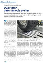
3 Outline<br />
3.1 Principle/structure<br />
The deniroll ® curve support is a roller component to provide<br />
horizontal support to the inner curve in curved modular<br />
belts (fi g. 3.1.1). The rotating rollers are contained in a roller<br />
belt (3) that is guided in both guidance plates (1 <strong>and</strong> 2) in a<br />
groove (5) (fi g. 3.1.2). The structure shown is an example <strong>and</strong><br />
the design can be different, while the principle <strong>of</strong> how it<br />
works is the same.<br />
The support can be retr<strong>of</strong>i tted in existing conveyors.<br />
➍<br />
Fig. 3.1.2<br />
b K<br />
➋<br />
➌<br />
➊<br />
➎<br />
u K<br />
Fig. 3.2 – view from the middle <strong>of</strong> the curve<br />
α<br />
r M<br />
r K<br />
Fig. 3.1.1 – view <strong>of</strong> the inner radius <strong>of</strong> the curve<br />
1 Bottom <strong>of</strong> guidance plate <strong>with</strong> guidance groove (5)<br />
2 Top <strong>of</strong> guidance plate<br />
3 Roller belt <strong>with</strong> rollers<br />
4 Connecting screws<br />
3.2 Main body/technical details<br />
α curve angle (specifi c to order)<br />
r curve radius K (specifi c to order =<br />
inner radius <strong>of</strong> the modular belt)<br />
r assembly radius M (r – 30 mm;<br />
K<br />
assembly drill holes specifi c to<br />
order M6 or M8)<br />
b width K 56 mm<br />
u length <strong>of</strong> the curve protrusion (specifi c to order)<br />
K<br />
Main body <strong>of</strong> the deniroll ® curve support which is specifi c to<br />
the order concerned is stated in the order confi rmation from<br />
denipro.<br />
bmaKA_V1_E_2009.09_1000<br />
4
3.3 Types/included <strong>with</strong> product<br />
The deniroll ® curve support is one <strong>of</strong> the three types shown.<br />
The types are different in the way the guidance plate<br />
protrudes (fi gs. 3.3.1 – 3.3.3).<br />
Fig. 3.3.1 – VB type<br />
(guidance plate protrudes on both sides)<br />
Fig. 3.3.2 – VO type<br />
(guidance plate protrudes at the top)<br />
Fig. 3.3.3 – RB type<br />
(guidance plate is retracted on both sides)<br />
5 bmaKA_V1_E_2009.09_1000<br />
Fig. 3.3.4 – (Insertion opening for the roller belt)<br />
Depending on the geometry <strong>of</strong> the curves, deniroll ® curve<br />
supports are supplied <strong>with</strong> or <strong>with</strong>out insertion opening for<br />
the roller belt (fi g. 3.3.4).<br />
3.4 Storage<br />
deniroll ® curve supports should only be stored in the<br />
following conditions:<br />
– No direct exposure to the sun,<br />
– Temperature +10 to +40°C,<br />
– 50% humidity,<br />
– Without any chemical or mechanical interference
4 Assembly<br />
4.1 Assembly instructions<br />
The deniroll ® curve support (1) is affi xed <strong>with</strong> metal brackets<br />
(2) or other components to the frame <strong>of</strong> the curve (3)<br />
(fi g. 4.1.1). Metal brackets <strong>with</strong> long holes make positioning<br />
easier.<br />
Fig. 4.1.1<br />
➊<br />
➋<br />
Attention<br />
The components used to affi x the curve support must<br />
be designed in such a way that they reliably absorb the<br />
radial forces <strong>and</strong> the moments that occur as a result<br />
<strong>with</strong>out deforming.<br />
4.2 Assembly tolerances<br />
Attention<br />
The conveying line must be geometrically correctly<br />
positioned for the deniroll ® curve support to work<br />
reliably.<br />
The following fault tolerances must be complied <strong>with</strong> during<br />
fi tting:<br />
– Angle fault a to the curve path ≤ 1° (Fig. 4.2.1)<br />
– Angle fault ß to the conveying level ≤ 0,5° (Fig. 4.2.2)<br />
– Maximum height difference between all contact points<br />
mass a ≤ 1 mm (Fig. 4.2.3)<br />
➌<br />
Fig. 4.2.1<br />
Fig. 4.2.2<br />
Fig. 4.2.3<br />
α<br />
β<br />
a<br />
bmaKA_V1_E_2009.09_1000<br />
6
Fig. 4.3.1<br />
Fig. 4.3.2<br />
Fig. 4.3.3<br />
Fig. 4.3.4<br />
➌<br />
➋<br />
➊<br />
➍<br />
7 bmaKA_V1_E_2009.09_1000<br />
➎<br />
➊<br />
4.3 Retr<strong>of</strong>i tting procedure<br />
1. Switch <strong>of</strong>f the conveyor <strong>and</strong> secure from being switched<br />
on again.<br />
Caution<br />
Before carrying out any assembly, maintenance <strong>and</strong><br />
repair work, the main switch on the conveyor must<br />
be switched <strong>of</strong>f <strong>and</strong> prevented from being switched<br />
on again.<br />
2 Open the modular belt around the curve in accordance<br />
<strong>with</strong> the conveyor manufacturer’s instructions <strong>and</strong> if<br />
necessary remove the old guidance section.<br />
Comment<br />
In the inner radius, the conveyor frame can be in the way<br />
<strong>of</strong> the deniroll ® curve support <strong>and</strong> if this is the case a<br />
notch must be applied.<br />
3 Mark out the exact positions <strong>of</strong> the drill holes on an<br />
auxiliary plate (1). Make drill holes to fi t the diameter <strong>of</strong><br />
the screws (fi g. 4.3.1).<br />
4 Position <strong>and</strong> affi x, or adequately weight down the<br />
auxiliary plate (1) on the curve’s slider bed (2) or the<br />
sliding strips in accordance <strong>with</strong> section 4.2. (fi g. 4.3.2).<br />
5 Provisionally affi x the components concerned (3) – in<br />
this case the brackets – in the right position. The right<br />
distance from the top edge <strong>of</strong> the slider bed can be<br />
achieved by applying spacers that are thick enough (4).<br />
Fit fi xing components (3) to the inner radius <strong>of</strong> the curve<br />
(fi g. 4.3.3).<br />
Comment<br />
The fi tting height must be selected so that the modular<br />
belt does not come into contact <strong>with</strong> any fi xed parts <strong>of</strong><br />
the deniroll ® curve support <strong>and</strong> so that as much as<br />
possible <strong>of</strong> the areas at the side runs on the rollers.<br />
6 Loosen the screws between the fastening components<br />
<strong>and</strong> the auxiliary plate. Remove the auxiliary plate <strong>and</strong><br />
spacers.<br />
7 Assemble the deniroll ® curve support (5). Check the<br />
positioning <strong>of</strong> the curve support in accordance <strong>with</strong><br />
section 4.1 <strong>and</strong> correct if necessary (fi g. 4.3.4).<br />
8 Close the belt in the curve according to the conveyor<br />
manufacturer’s instructions.<br />
9 Check the positioning <strong>of</strong> the deniroll ® curve support again<br />
<strong>and</strong> adjust if necessary.<br />
– The play in the whole <strong>of</strong> the curve should be<br />
constant between the modular belts <strong>and</strong> any<br />
protruding guidance plates.<br />
– The modular belt must not come into contact <strong>with</strong> any<br />
fi xed parts on the deniroll ® curve support.<br />
10 Commission the conveyor according to the conveyor<br />
manufacturer’s instructions.
5 Operation<br />
5.1 Commissioning/re-commissioning<br />
Examine the inner radius <strong>of</strong> the curve to ensure there are no<br />
foreign bodies <strong>and</strong> if necessary remove these. Switch on the<br />
conveyor <strong>and</strong> observe. If the deniroll ® curve support is not<br />
operating evenly <strong>and</strong> <strong>with</strong>out vibrating, switch <strong>of</strong>f the<br />
conveyor <strong>and</strong> eliminate the problems. One <strong>of</strong> the causes <strong>of</strong><br />
uneven tracking can be assembly faults <strong>and</strong> foreign bodies.<br />
5.2 Shutting down<br />
To shut down, the system must be switched <strong>of</strong>f at the main<br />
switch <strong>and</strong> secured from being switched on again.<br />
Caution<br />
The machinery must be shut down in particular before<br />
all assembly, maintenance <strong>and</strong> repair work is carried<br />
out.<br />
5.3 Disposal<br />
Disposal must be carried out in line <strong>with</strong> valid stipulations.<br />
6 Maintenance/cleaning<br />
6.1 Maintenance<br />
The deniroll ® curve support needs no maintenance <strong>and</strong> must<br />
never be lubricated.<br />
6.2 Cleaning<br />
Soiling can lead to incr<strong>ease</strong>d wear <strong>and</strong> tear on the deniroll ®<br />
curve support <strong>and</strong> other components on the conveyor. To<br />
guarantee the curve support works perfectly, we recommend<br />
you clean it regularly. Cleaning intervals <strong>and</strong> methods depend<br />
on the level <strong>of</strong> soiling <strong>and</strong> the specifi cations from the conveyor<br />
manufacturer. Cleaning can be carried out in the<br />
following ways:<br />
– By water jet <strong>with</strong> low rinsing pressure or<br />
– Carefully, from a distance <strong>with</strong> a water jet at high pressure<br />
(fl at fan nozzle).<br />
In both cases, commonly available mild cleaning agents can<br />
be used.<br />
Attention<br />
Particularly in the food industry, hygiene regulations,<br />
the relevant statutory specifi cations <strong>and</strong> the regulations<br />
laid down by the machinery manufacturers must be<br />
complied <strong>with</strong>.<br />
bmaKA_V1_E_2009.09_1000<br />
8
7 Repair<br />
The appearance <strong>of</strong> the roller belt should be checked at<br />
regular intervals, e. g. when maintenance is carried out<br />
on the conveyor. If there are any signs <strong>of</strong> wear <strong>and</strong> tear,<br />
the roller belt must be exchanged.<br />
Fig. 7.1.1<br />
Fig. 7.1.2<br />
Fig. 7.1.3<br />
Fig. 7.1.4<br />
➌<br />
➊<br />
➋<br />
➊<br />
9 bmaKA_V1_E_2009.09_1000<br />
Signs <strong>of</strong> an incr<strong>ease</strong> in wear <strong>and</strong> tear are elongation<br />
<strong>of</strong> the roller belt, uneven tracking, as well as other<br />
indications <strong>of</strong> wear <strong>and</strong> tear such as for example<br />
abrasion.<br />
7.1 Exchanging the roller belt in curve supports<br />
<strong>with</strong> insertion opening<br />
1 Switch <strong>of</strong>f the conveyor <strong>and</strong> secure from being switched<br />
on again.<br />
Caution<br />
Before carrying out any assembly, maintenance <strong>and</strong><br />
repair work, the main switch on the conveyor must<br />
be switched <strong>of</strong>f <strong>and</strong> prevented from being switched<br />
on again.<br />
2 Close the belt in the curve according to the conveyor<br />
manufacturer’s instructions.<br />
3 Roll the overlap splice on the roller belt (1) by h<strong>and</strong><br />
towards the insertion opening (2) (fi g. 7.1.1).<br />
4 Open the overlap splice <strong>with</strong> a narrow screw driver<br />
(fi g. 7.1.2) <strong>and</strong> pull out the old roller belt (1) from the<br />
guidance groove (fi g. 7.1.3).<br />
5 Insert the new roller belt (3) in the guidance groove<br />
(fi g. 7.1.4) until the fi rst 3 rollers reappear in the opening<br />
(fi g. 7.1.5).<br />
Comment<br />
When exchanging the roller belt, the previous <strong>and</strong> new<br />
length must be the same. The roller belt must never be<br />
pre-tensioned or too long. The original direction <strong>of</strong> the<br />
overlap should be maintained.
Fig. 7.1.5<br />
Fig. 7.1.7<br />
Fig. 7.2.1<br />
➍<br />
➋<br />
➊<br />
Fig. 7.1.6<br />
6 Remove the last three rollers from the roller belt<br />
(fi g. 7.1.6).<br />
7 At the overlap, lift the roller belt fl aps (4) <strong>with</strong> a narrow<br />
screwdriver into the rollers on the inside (fi g. 7.1.7).<br />
8 Close the belt in the curve according to the conveyor<br />
manufacturer’s instructions.<br />
9 Check by h<strong>and</strong> that the roller chain moves easily.<br />
10 Commission according to section 5.<br />
7.2 Exchanging the roller belt in curve supports<br />
<strong>with</strong>out insertion opening<br />
1 Switch <strong>of</strong>f the conveyor <strong>and</strong> secure from being switched<br />
on again.<br />
Caution<br />
Before carrying out any assembly, maintenance <strong>and</strong><br />
repair work, the main switch on the conveyor must<br />
be switched <strong>of</strong>f <strong>and</strong> prevented from being switched<br />
on again.<br />
2 Open the belt in the curve according to the conveyor<br />
manufacturer’s instructions.<br />
3 Where the curve protrudes, unscrew the screws (1) on the<br />
top guidance plate segment (2) <strong>and</strong> remove the segment<br />
(fi g. 7.2.1).<br />
4 Exchange the roller chain as for steps 3 <strong>and</strong> 7 in<br />
section 7.1.<br />
5 Affi x the guidance plate (2).<br />
6 Check by h<strong>and</strong> that the roller chain moves easily.<br />
7 Close the belt in the curve according to the conveyor<br />
manufacturer’s instructions.<br />
8 Commission according to section 5.<br />
bmaKA_V1_E_2009.09_1000<br />
10
8 <strong>Declaration</strong> <strong>of</strong> incorporation for incomplete machinery<br />
Assembly declaration in line <strong>with</strong> EC machine directive 2006/42/EC, appendix II b<br />
Incomplete machine: deniroll ® Kurvenabstützung;<br />
roller element for horizontal support <strong>of</strong> curved modular belts.<br />
Designation: deniroll ® curve support<br />
Manufacturer: Denipro AG<br />
Tannenwiesenstrasse 5<br />
CH-8570 Weinfelden<br />
Person authorised to compile the<br />
assembly <strong>and</strong> operating instructions: Marco de Angelis<br />
Denipro AG<br />
Tannenwiesenstrasse 5<br />
CH-8570 Weinfelden<br />
The manufacturer declares that the above-mentioned incomplete machine complies <strong>with</strong> the basic health <strong>and</strong> safety requirements <strong>of</strong><br />
the EC machine directive 2006/42/EC, appendix 1.<br />
The technical documentation <strong>of</strong> this incomplete machine was drawn up in accordance <strong>with</strong> the EC machine directive 2006/42/EC,<br />
appendix VII part B.<br />
The manufacturer undertakes to forward these technical documents to government bodies if good reasons are given.<br />
Commissioning <strong>of</strong> the incomplete machine is prohibited until the incomplete machine is inserted into a machine <strong>and</strong> such machine<br />
complies <strong>with</strong> the regulations set out in the EC machine directive <strong>and</strong> an EC declaration <strong>of</strong> compliance in accordance <strong>with</strong> appendix II A<br />
has been obtained.<br />
Denipro AG<br />
CH-8570 Weinfelden, 30.8.2009<br />
Marco de Angelis<br />
(Head <strong>of</strong> development)<br />
11 bmaKA_V1_E_2009.09_1000
Denipro AG<br />
Tannenwiesenstrasse 5<br />
CH-8570 Weinfelden<br />
Telefon +41 71 626 47 47<br />
Fax +41 71 626 48 48<br />
info@denipro.com<br />
www.denipro.com<br />
bmaKA_V1_E_2009.09_1000