Operation and Maintenance Manual
Engine - JLG
Engine - JLG
- No tags were found...

Create successful ePaper yourself
Turn your PDF publications into a flip-book with our unique Google optimized e-Paper software.
SEBU8180-01<br />
March 2008<br />
<strong>Operation</strong> <strong>and</strong><br />
<strong>Maintenance</strong><br />
<strong>Manual</strong><br />
C4.4 Industrial Engine<br />
4441-Up (Engine)<br />
SAFETY.CAT.COM
Important Safety Information<br />
i01658146<br />
Most accidents that involve product operation, maintenance <strong>and</strong> repair are caused by failure to observe<br />
basic safety rules or precautions. An accident can often be avoided by recognizing potentially hazardous<br />
situations before an accident occurs. A person must be alert to potential hazards. This person should also<br />
have the necessary training, skills <strong>and</strong> tools to perform these functions properly.<br />
Improper operation, lubrication, maintenance or repair of this product can be dangerous <strong>and</strong><br />
could result in injury or death.<br />
Do not operate or perform any lubrication, maintenance or repair on this product, until you have<br />
read <strong>and</strong> understood the operation, lubrication, maintenance <strong>and</strong> repair information.<br />
Safety precautions <strong>and</strong> warnings are provided in this manual <strong>and</strong> on the product. If these hazard warnings<br />
are not heeded, bodily injury or death could occur to you or to other persons.<br />
The hazards are identified by the “Safety Alert Symbol” <strong>and</strong> followed by a “Signal Word” such as<br />
“DANGER”, “WARNING” or “CAUTION”. The Safety Alert “WARNING” label is shown below.<br />
The meaning of this safety alert symbol is as follows:<br />
Attention! Become Alert! Your Safety is Involved.<br />
The message that appears under the warning explains the hazard <strong>and</strong> can be either written or pictorially<br />
presented.<br />
<strong>Operation</strong>s that may cause product damage are identified by “NOTICE” labels on the product <strong>and</strong> in<br />
this publication.<br />
Caterpillar cannot anticipate every possible circumstance that might involve a potential hazard.<br />
The warnings in this publication <strong>and</strong> on the product are, therefore, not all inclusive. If a tool,<br />
procedure, work method or operating technique that is not specifically recommended by Caterpillar<br />
is used, you must satisfy yourself that it is safe for you <strong>and</strong> for others. You should also ensure that<br />
the product will not be damaged or be made unsafe by the operation, lubrication, maintenance or<br />
repair procedures that you choose.<br />
The information, specifications, <strong>and</strong> illustrations in this publication are on the basis of information that<br />
was available at the time that the publication was written. The specifications, torques, pressures,<br />
measurements, adjustments, illustrations, <strong>and</strong> other items can change at any time. These changes can<br />
affect the service that is given to the product. Obtain the complete <strong>and</strong> most current information before you<br />
start any job. Caterpillar dealers have the most current information available.<br />
When replacement parts are required for this<br />
product Caterpillar recommends using Caterpillar<br />
replacement parts or parts with equivalent<br />
specifications including, but not limited to, physical<br />
dimensions, type, strength <strong>and</strong> material.<br />
Failure to heed this warning can lead to premature<br />
failures, product damage, personal injury or<br />
death.
SEBU8180-01 3<br />
Table of Contents<br />
Table of Contents<br />
Foreword ................................................................. 4<br />
Safety Section<br />
Safety Messages .................................................... 6<br />
General Hazard Information ................................... 8<br />
Burn Prevention ..................................................... 11<br />
Fire Prevention <strong>and</strong> Explosion Prevention ............ 12<br />
Crushing Prevention <strong>and</strong> Cutting Prevention ........ 14<br />
Mounting <strong>and</strong> Dismounting ................................... 14<br />
<strong>Maintenance</strong> Interval Schedule ............................ 61<br />
Warranty Section<br />
Warranty Information .......................................... 102<br />
Reference Information Section<br />
Engine Ratings ................................................... 103<br />
Customer Service ............................................... 104<br />
Reference Materials ............................................ 106<br />
Index Section<br />
Index .................................................................... 110<br />
High Pressure Fuel Lines ..................................... 14<br />
Before Starting Engine .......................................... 16<br />
Engine Starting ..................................................... 16<br />
Engine Stopping ................................................... 17<br />
Electrical System .................................................. 17<br />
Engine Electronics ................................................ 18<br />
Product Information Section<br />
General Information .............................................. 19<br />
Model Views ......................................................... 20<br />
Product Identification Information ........................ 25<br />
<strong>Operation</strong> Section<br />
Lifting <strong>and</strong> Storage ................................................ 28<br />
Gauges <strong>and</strong> Indicators .......................................... 29<br />
Features <strong>and</strong> Controls .......................................... 31<br />
Engine Diagnostics ............................................... 38<br />
Engine Starting ..................................................... 42<br />
Engine <strong>Operation</strong> .................................................. 45<br />
Engine Stopping ................................................... 47<br />
Cold Weather <strong>Operation</strong> ....................................... 49<br />
<strong>Maintenance</strong> Section<br />
Refill Capacities .................................................... 54
4 SEBU8180-01<br />
Foreword<br />
Foreword<br />
Literature Information<br />
This manual contains safety, operation instructions,<br />
lubrication <strong>and</strong> maintenance information. This<br />
manual should be stored in or near the engine area<br />
in a literature holder or literature storage area. Read,<br />
study <strong>and</strong> keep it with the literature <strong>and</strong> engine<br />
information.<br />
English is the primary language for all Caterpillar<br />
publications. The English used facilitates translation<br />
<strong>and</strong> consistency in electronic media delivery.<br />
Some photographs or illustrations in this manual<br />
show details or attachments that may be different<br />
from your engine. Guards <strong>and</strong> covers may have<br />
been removed for illustrative purposes. Continuing<br />
improvement <strong>and</strong> advancement of product design<br />
may have caused changes to your engine which are<br />
not included in this manual. Whenever a question<br />
arises regarding your engine, or this manual, please<br />
consult with your Caterpillar dealer for the latest<br />
available information.<br />
Safety<br />
This safety section lists basic safety precautions.<br />
In addition, this section identifies hazardous,<br />
warning situations. Read <strong>and</strong> underst<strong>and</strong> the basic<br />
precautions listed in the safety section before<br />
operating or performing lubrication, maintenance <strong>and</strong><br />
repair on this product.<br />
<strong>Operation</strong><br />
Operating techniques outlined in this manual are<br />
basic. They assist with developing the skills <strong>and</strong><br />
techniques required to operate the engine more<br />
efficiently <strong>and</strong> economically. Skill <strong>and</strong> techniques<br />
develop as the operator gains knowledge of the<br />
engine <strong>and</strong> its capabilities.<br />
The operation section is a reference for operators.<br />
Photographs <strong>and</strong> illustrations guide the operator<br />
through procedures of inspecting, starting, operating<br />
<strong>and</strong> stopping the engine. This section also includes a<br />
discussion of electronic diagnostic information.<br />
<strong>Maintenance</strong><br />
The maintenance section is a guide to engine care.<br />
The illustrated, step-by-step instructions are grouped<br />
by fuel consumption, service hours <strong>and</strong>/or calendar<br />
time maintenance intervals. Items in the maintenance<br />
schedule are referenced to detailed instructions that<br />
follow.<br />
Use fuel consumption or service hours to determine<br />
intervals. Calendar intervals shown (daily, annually,<br />
etc.) may be used instead of service meter intervals<br />
if they provide more convenient schedules <strong>and</strong><br />
approximate the indicated service meter reading.<br />
Recommended service should be performed at the<br />
appropriate intervals as indicated in the <strong>Maintenance</strong><br />
Interval Schedule. The actual operating environment<br />
of the engine also governs the <strong>Maintenance</strong> Interval<br />
Schedule. Therefore, under extremely severe,<br />
dusty, wet or freezing cold operating conditions,<br />
more frequent lubrication <strong>and</strong> maintenance than is<br />
specified in the <strong>Maintenance</strong> Interval Schedule may<br />
be necessary.<br />
The maintenance schedule items are organized for<br />
a preventive maintenance management program. If<br />
the preventive maintenance program is followed, a<br />
periodic tune-up is not required. The implementation<br />
of a preventive maintenance management program<br />
should minimize operating costs through cost<br />
avoidances resulting from reductions in unscheduled<br />
downtime <strong>and</strong> failures.<br />
<strong>Maintenance</strong> Intervals<br />
Perform maintenance on items at multiples of the<br />
original requirement. Each level <strong>and</strong>/or individual<br />
items in each level should be shifted ahead or back<br />
depending upon your specific maintenance practices,<br />
operation <strong>and</strong> application. We recommend that<br />
the maintenance schedules be reproduced <strong>and</strong><br />
displayed near the engine as a convenient reminder.<br />
We also recommend that a maintenance record be<br />
maintained as part of the engine’s permanent record.<br />
See the section in the <strong>Operation</strong> <strong>and</strong> <strong>Maintenance</strong><br />
<strong>Manual</strong>, “<strong>Maintenance</strong> Records” for information<br />
regarding documents that are generally accepted<br />
as proof of maintenance or repair. Your authorized<br />
Caterpillar dealer can assist you in adjusting your<br />
maintenance schedule to meet the needs of your<br />
operating environment.<br />
Overhaul<br />
Major engine overhaul details are not covered in the<br />
<strong>Operation</strong> <strong>and</strong> <strong>Maintenance</strong> <strong>Manual</strong> except for the<br />
interval <strong>and</strong> the maintenance items in that interval.<br />
Major repairs are best left to trained personnel or<br />
an authorized Caterpillar dealer. Your Caterpillar<br />
dealer offers a variety of options regarding overhaul<br />
programs. If you experience a major engine failure,<br />
there are also numerous after failure overhaul options<br />
available from your Caterpillar dealer. Consult with<br />
your dealer for information regarding these options.
SEBU8180-01 5<br />
Foreword<br />
California Proposition 65 Warning<br />
Diesel engine exhaust <strong>and</strong> some of its constituents<br />
are known to the State of California to cause cancer,<br />
birth defects, <strong>and</strong> other reproductive harm.<br />
Battery posts, terminals <strong>and</strong> related accessories<br />
contain lead <strong>and</strong> lead compounds. Wash h<strong>and</strong>s<br />
after h<strong>and</strong>ling.
6 SEBU8180-01<br />
Safety Section<br />
Safety Messages<br />
Safety Section<br />
Safety Messages<br />
SMCS Code: 1000; 7405<br />
i02872106<br />
The Universal Warning label (1) is located on both<br />
sides of the valve mechanism cover base. Refer to<br />
illustration 2.<br />
There may be several specific warning signs on your<br />
engine. The exact location <strong>and</strong> a description of the<br />
warning signs are reviewed in this section. Please<br />
become familiar with all warning signs.<br />
Ensure that all of the warning signs are legible. Clean<br />
the warning signs or replace the warning signs if<br />
the words cannot be read or if the illustrations are<br />
not visible. Use a cloth, water, <strong>and</strong> soap to clean<br />
the warning signs. Do not use solvents, gasoline, or<br />
other harsh chemicals. Solvents, gasoline, or harsh<br />
chemicals could loosen the adhesive that secures the<br />
warning signs. The warning signs that are loosened<br />
could drop off of the engine.<br />
Replace any warning sign that is damaged or<br />
missing.Ifawarningsignisattachedtoapartofthe<br />
engine that is replaced, install a new warning sign<br />
on the replacement part. Your Caterpillar dealer can<br />
provide new warning signs.<br />
(1) Universal Warning<br />
Do not operate or work on this equipment unless<br />
you have read <strong>and</strong> underst<strong>and</strong> the instructions<br />
<strong>and</strong> warnings in the <strong>Operation</strong> <strong>and</strong> <strong>Maintenance</strong><br />
<strong>Manual</strong>s. Failure to follow the instructions or<br />
heed the warnings could result in serious injury<br />
or death.<br />
Illustration 1<br />
Typical example<br />
g01154807
SEBU8180-01 7<br />
Safety Section<br />
Safety Messages<br />
Illustration 2<br />
(1) Universal warning<br />
(2) H<strong>and</strong> (High Pressure)<br />
g01268960<br />
The warning label for the H<strong>and</strong> (High Pressure) (2)<br />
is located on the top of the fuel manifold. Refer to<br />
illustration 4.<br />
Contact with high pressure fuel may cause fluid<br />
penetration <strong>and</strong> burn hazards. High pressure fuel<br />
spray may cause a fire hazard. Failure to follow<br />
these inspection, maintenance <strong>and</strong> service instructions<br />
may cause personal injury or death.<br />
Illustration 3<br />
Typical example<br />
g01154858
8 SEBU8180-01<br />
Safety Section<br />
General Hazard Information<br />
Illustration 4<br />
(2) H<strong>and</strong> (High Pressure) (3) Ether<br />
(3) Ether<br />
g01430275<br />
Note: The position of this label will depend on the<br />
application on the engine.<br />
Do not use aerosol types of starting aids such as<br />
ether. Such use could result in an explosion <strong>and</strong><br />
personal injury.<br />
i02344741<br />
General Hazard Information<br />
SMCS Code: 1000; 7405<br />
Illustration 5<br />
Typical example<br />
g01154809<br />
Illustration 6<br />
g00104545<br />
The ether warning label (3) is located on the cover of<br />
the inlet manifold. Refer to illustration 4.
SEBU8180-01 9<br />
Safety Section<br />
General Hazard Information<br />
Attach a “Do Not Operate” warning tag or a similar<br />
warning tag to the start switch or to the controls<br />
before the engine is serviced or before the engine is<br />
repaired. These warning tags (Special Instruction,<br />
SEHS7332) are available from your Caterpillar<br />
dealer. Attach the warning tags to the engine <strong>and</strong> to<br />
each operator control station. When it is appropriate,<br />
disconnect the starting controls.<br />
Do not allow unauthorized personnel on the engine,<br />
or around the engine when the engine is being<br />
serviced.<br />
Engine exhaust contains products of combustion<br />
which may be harmful to your health. Always start the<br />
engine <strong>and</strong> operate the engine in a well ventilated<br />
area. If the engine is in an enclosed area, vent the<br />
engine exhaust to the outside.<br />
Cautiously remove the following parts. To help<br />
prevent spraying or splashing of pressurized fluids,<br />
holdaragover the part that is being removed.<br />
• Filler caps<br />
• Grease fittings<br />
• Pressure taps<br />
• Breathers<br />
• Drain plugs<br />
Use caution when cover plates are removed.<br />
Gradually loosen, but do not remove the last two<br />
bolts or nuts that are located at opposite ends of<br />
the cover plate or the device. Before removing the<br />
last two bolts or nuts, pry the cover loose in order to<br />
relieve any spring pressure or other pressure.<br />
• Do not wear loose clothing or jewelry that can snag<br />
on controls or on other parts of the engine.<br />
• Ensure that all protective guards <strong>and</strong> all covers are<br />
securedinplaceontheengine.<br />
• Never put maintenance fluids into glass containers.<br />
Glass containers can break.<br />
• Use all cleaning solutions with care.<br />
• Report all necessary repairs.<br />
Unless other instructions are provided, perform<br />
the maintenance under the following conditions:<br />
• The engine is stopped. Ensure that the engine<br />
cannot be started.<br />
• Disconnect the batteries when maintenance<br />
is performed or when the electrical system is<br />
serviced. Disconnect the battery ground leads.<br />
Tape the leads in order to help prevent sparks.<br />
• Do not attempt any repairs that are not understood.<br />
Use the proper tools. Replace any equipment that<br />
is damaged or repair the equipment.<br />
Pressurized Air <strong>and</strong> Water<br />
Pressurized air <strong>and</strong>/or water can cause debris<br />
<strong>and</strong>/or hot water to be blown out. This could result in<br />
personal injury.<br />
When pressurized air <strong>and</strong>/or pressurized water is<br />
used for cleaning, wear protective clothing, protective<br />
shoes, <strong>and</strong> eye protection. Eye protection includes<br />
goggles or a protective face shield.<br />
The maximum air pressure for cleaning purposes<br />
must be below 205 kPa (30 psi). The maximum<br />
water pressure for cleaning purposes must be below<br />
275 kPa (40 psi).<br />
Fluid Penetration<br />
Pressure can be trapped in the hydraulic circuit long<br />
after the engine has been stopped. The pressure can<br />
cause hydraulic fluid or items such as pipe plugs to<br />
escape rapidly if the pressure is not relieved correctly.<br />
Illustration 7<br />
g00702020<br />
• Wear a hard hat, protective glasses, <strong>and</strong> other<br />
protective equipment, as required.<br />
• When work is performed around an engine that is<br />
operating, wear protective devices for ears in order<br />
to help prevent damage to hearing.<br />
Do not remove any hydraulic components or parts<br />
until pressure has been relieved or personal injury<br />
may occur. Do not disassemble any hydraulic<br />
components or parts until pressure has been relieved<br />
or personal injury may occur. Refer to the OEM<br />
information for any procedures that are required to<br />
relieve the hydraulic pressure.
10 SEBU8180-01<br />
Safety Section<br />
General Hazard Information<br />
Asbestos Information<br />
Illustration 8<br />
g00687600<br />
Always use a board or cardboard when you check<br />
for a leak. Leaking fluid that is under pressure can<br />
penetrate body tissue. Fluid penetration can cause<br />
serious injury <strong>and</strong> possible death. A pin hole leak can<br />
cause severe injury. If fluid is injected into your skin,<br />
you must get treatment immediately. Seek treatment<br />
from a doctor that is familiar with this type of injury.<br />
Containing Fluid Spillage<br />
Care must be taken in order to ensure that fluids<br />
are contained during performance of inspection,<br />
maintenance, testing, adjusting <strong>and</strong> repair of the<br />
engine. Prepare to collect the fluid with suitable<br />
containers before opening any compartment or<br />
disassembling any component that contains fluids.<br />
Refer to Special Publication, NENG2500, “Dealer<br />
Service Tool Catalog” for the following items:<br />
• Tools that are suitable for collecting fluids <strong>and</strong><br />
equipment that is suitable for collecting fluids<br />
• Tools that are suitable for containing fluids <strong>and</strong><br />
equipment that is suitable for containing fluids<br />
Obey all local regulations for the disposal of liquids.<br />
Illustration 9<br />
g00702022<br />
Caterpillar equipment <strong>and</strong> replacement parts that are<br />
shipped from Caterpillar are asbestos free. Caterpillar<br />
recommends the use of only genuine Caterpillar<br />
replacement parts. Use the following guidelines<br />
when you h<strong>and</strong>le any replacement parts that contain<br />
asbestos or when you h<strong>and</strong>le asbestos debris.<br />
Use caution. Avoid inhaling dust that might be<br />
generated when you h<strong>and</strong>le components that contain<br />
asbestos fibers. Inhaling this dust can be hazardous<br />
to your health. The components that may contain<br />
asbestos fibers are brake pads, brake b<strong>and</strong>s, lining<br />
material, clutch plates, <strong>and</strong> some gaskets. The<br />
asbestos that is used in these components is usually<br />
bound in a resin or sealed in some way. Normal<br />
h<strong>and</strong>ling is not hazardous unless airborne dust that<br />
contains asbestos is generated.<br />
If dust that may contain asbestos is present, there<br />
are several guidelines that should be followed:<br />
• Never use compressed air for cleaning.<br />
• Avoid brushing materials that contain asbestos.<br />
• Avoid grinding materials that contain asbestos.<br />
• Useawetmethodinordertocleanupasbestos<br />
materials.<br />
• A vacuum cleaner that is equipped with a high<br />
efficiency particulate air filter (HEPA) can also be<br />
used.<br />
• Use exhaust ventilation on permanent machining<br />
jobs.<br />
• Wear an approved respirator if there is no other<br />
way to control the dust.
SEBU8180-01 11<br />
Safety Section<br />
Burn Prevention<br />
• Comply with applicable rules <strong>and</strong> regulations<br />
for the work place. In the United States, use<br />
Occupational Safety <strong>and</strong> Health Administration<br />
(OSHA) requirements. These OSHA requirements<br />
can be found in “29 CFR 1910.1001”.<br />
• Obey environmental regulations for the disposal<br />
of asbestos.<br />
• Stay away from areas that might have asbestos<br />
particles in the air.<br />
Dispose of Waste Properly<br />
Allow the pressure to be purged in the air system, in<br />
the hydraulic system, in the lubrication system, or in<br />
the cooling system before any lines, fittings or related<br />
items are disconnected.<br />
Coolant<br />
When the engine is at operating temperature, the<br />
engine coolant is hot. The coolant is also under<br />
pressure. The radiator <strong>and</strong> all lines to the heaters or<br />
to the engine contain hot coolant.<br />
Any contact with hot coolant or with steam can cause<br />
severe burns. Allow cooling system components to<br />
cool before the cooling system is drained.<br />
Check the coolant level after the engine has stopped<br />
<strong>and</strong> the engine has been allowed to cool.<br />
Ensure that the filler cap is cool before removing the<br />
filler cap. The filler cap must be cool enough to touch<br />
with a bare h<strong>and</strong>. Remove the filler cap slowly in<br />
order to relieve pressure.<br />
Cooling system conditioner contains alkali. Alkali can<br />
cause personal injury. Do not allow alkali to contact<br />
the skin, the eyes, or the mouth.<br />
Illustration 10<br />
g00706404<br />
Improperly disposing of waste can threaten the<br />
environment. Potentially harmful fluids should be<br />
disposed of according to local regulations.<br />
Always use leakproof containers when you drain<br />
fluids. Do not pour waste onto the ground, down a<br />
drain, or into any source of water.<br />
Oils<br />
Hot oil <strong>and</strong> hot lubricating components can cause<br />
personal injury. Do not allow hot oil to contact the<br />
skin. Also, do not allow hot components to contact<br />
the skin.<br />
Batteries<br />
Burn Prevention<br />
SMCS Code: 1000; 7405<br />
i02344742<br />
Electrolyte is an acid. Electrolyte can cause personal<br />
injury. Do not allow electrolyte to contact the skin or<br />
the eyes. Always wear protective glasses for servicing<br />
batteries. Wash h<strong>and</strong>s after touching the batteries<br />
<strong>and</strong> connectors. Use of gloves is recommended.<br />
Do not touch any part of an operating engine.<br />
Allow the engine to cool before any maintenance is<br />
performed on the engine.<br />
Contact with high pressure fuel may cause fluid<br />
penetration <strong>and</strong> burn hazards. High pressure fuel<br />
spray may cause a fire hazard. Failure to follow<br />
these inspection, maintenance <strong>and</strong> service instructions<br />
may cause personal injury or death.<br />
After the engine has stopped, you must wait for 60<br />
seconds in order to allow the fuel pressure to be<br />
purged from the high pressure fuel lines before any<br />
service or repair is performed on the engine fuel lines.
12 SEBU8180-01<br />
Safety Section<br />
Fire Prevention <strong>and</strong> Explosion Prevention<br />
i02328452<br />
Fire Prevention <strong>and</strong> Explosion<br />
Prevention<br />
SMCS Code: 1000; 7405<br />
Do not weld on lines or tanks that contain flammable<br />
fluids. Do not flame cut lines or tanks that contain<br />
flammable fluid. Clean any such lines or tanks<br />
thoroughly withanonflammable solvent prior to<br />
welding or flame cutting.<br />
Wiring must be keptingoodcondition.Allelectrical<br />
wires must be properly routed <strong>and</strong> securely attached.<br />
Check all electrical wires daily. Repair any wires<br />
that are loose or frayed before you operate the<br />
engine. Clean all electrical connections <strong>and</strong> tighten<br />
all electrical connections.<br />
Illustration 11<br />
g00704000<br />
Eliminate all wiring that is unattached or unnecessary.<br />
Do not use any wires or cables that are smaller than<br />
the recommended gauge. Do not bypass any fuses<br />
<strong>and</strong>/or circuit breakers.<br />
Arcing or sparking could cause a fire. Secure<br />
connections, recommended wiring, <strong>and</strong> properly<br />
maintained battery cables will help to prevent arcing<br />
or sparking.<br />
All fuels, most lubricants, <strong>and</strong> some coolant mixtures<br />
are flammable.<br />
Flammable fluids that are leaking or spilled onto hot<br />
surfaces or onto electrical components can cause<br />
a fire. Fire may cause personal injury <strong>and</strong> property<br />
damage.<br />
A flash fire may result if the covers for the engine<br />
crankcase are removed within fifteen minutes after<br />
an emergency shutdown.<br />
Determine whether the engine will be operated in an<br />
environment that allows combustible gases to be<br />
drawn into the air inlet system. These gases could<br />
cause the engine to overspeed. Personal injury,<br />
property damage, or engine damage could result.<br />
If the application involves the presence of combustible<br />
gases, consult your Caterpillar dealer for additional<br />
information about suitable protection devices.<br />
Remove all flammable materials such as fuel, oil, <strong>and</strong><br />
debris from the engine. Do not allow any flammable<br />
materials to accumulate on the engine.<br />
Contact with high pressure fuel may cause fluid<br />
penetration <strong>and</strong> burn hazards. High pressure fuel<br />
spray may cause a fire hazard. Failure to follow<br />
these inspection, maintenance <strong>and</strong> service instructions<br />
may cause personal injury or death.<br />
After the engine has stopped, you must wait for 60<br />
seconds in order to allow the fuel pressure to be<br />
purged from the high pressure fuel lines before any<br />
service or repair is performed on the engine fuel lines.<br />
Inspect all lines <strong>and</strong> hoses for wear or for<br />
deterioration. The hoses must be properly routed.<br />
The lines <strong>and</strong> hoses must have adequate support<br />
<strong>and</strong> secure clamps. Tighten all connections to the<br />
recommended torque. Leaks can cause fires.<br />
Oil filters <strong>and</strong> fuel filters must be properly installed.<br />
The filter housings must be tightened to the proper<br />
torque.<br />
Store fuels <strong>and</strong> lubricants in properly marked<br />
containers away from unauthorized persons. Store<br />
oily rags <strong>and</strong>anyflammable materials in protective<br />
containers. Do not smoke in areas that are used for<br />
storing flammable materials.<br />
Do not expose the engine to any flame.<br />
Exhaust shields (if equipped) protect hot exhaust<br />
components from oil or fuel spray in case of a line,<br />
a tube, or a seal failure. Exhaust shields must be<br />
installed correctly.
SEBU8180-01 13<br />
Safety Section<br />
Fire Prevention <strong>and</strong> Explosion Prevention<br />
Improper jumper cable connections can cause<br />
an explosion that can result in injury. Refer to<br />
the <strong>Operation</strong> Section of this manual for specific<br />
instructions.<br />
Do not charge a frozen battery. This may cause an<br />
explosion.<br />
The batteries must be kept clean. The covers<br />
(if equipped) must be kept on the cells. Use the<br />
recommended cables, connections, <strong>and</strong> battery box<br />
covers when the engine is operated.<br />
Fire Extinguisher<br />
Make sure that a fire extinguisher is available. Be<br />
familiar with the operation of the fire extinguisher.<br />
Inspect the fire extinguisher <strong>and</strong> service the fire<br />
extinguisher regularly. Obey the recommendations<br />
on the instruction plate.<br />
Illustration 12<br />
g00704059<br />
Use caution when you are refueling an engine. Do<br />
not smoke while you are refueling an engine. Do not<br />
refuel an engine near open flames or sparks. Always<br />
stop the engine before refueling.<br />
Ether<br />
Ether is flammable <strong>and</strong> poisonous.<br />
Use ether in well ventilated areas. Do not smoke<br />
while you are replacing an ether cylinder or while you<br />
are using an ether spray.<br />
Do not store ether cylinders in living areas or in the<br />
engine compartment. Do not store ether cylinders<br />
in direct sunlight or in temperatures above 49 °C<br />
(120 °F). Keep ether cylinders away from open<br />
flames or sparks.<br />
Dispose of used ether cylinders properly. Do not<br />
puncture an ether cylinder. Keep ether cylinders<br />
away from unauthorized personnel.<br />
Do not spray ether into an engine if the engine is<br />
equipped with a thermal starting aid for cold weather<br />
starting.<br />
Lines, Tubes <strong>and</strong> Hoses<br />
Illustration 13<br />
g00704135<br />
Gases from a battery can explode. Keep any open<br />
flames or sparks away from the top of a battery. Do<br />
not smoke in battery charging areas.<br />
Never check the battery charge by placing a metal<br />
object across the terminal posts. Use a voltmeter or<br />
ahydrometer.<br />
Do not bend highpressurelines.Donotstrikehigh<br />
pressure lines. Do not install any lines that are bent<br />
or damaged.<br />
Repair any lines that are loose or damaged. Leaks<br />
can cause fires. Consult your Caterpillar dealer for<br />
repair or for replacement parts.<br />
Check lines, tubes <strong>and</strong> hoses carefully. Do not use<br />
your bare h<strong>and</strong>tocheckforleaks.Useaboardor<br />
cardboard to check for leaks. Tighten all connections<br />
to the recommended torque.<br />
Replace the parts if any of the following conditions<br />
are present:
14 SEBU8180-01<br />
Safety Section<br />
Crushing Prevention <strong>and</strong> Cutting Prevention<br />
• High pressure fuel line or lines are removed.<br />
• End fittings are damaged or leaking.<br />
• Outer coverings are chafed or cut.<br />
• Wires are exposed.<br />
• Outer coverings are ballooning.<br />
• Flexible part of the hoses are kinked.<br />
• Outer covers have embedded armoring.<br />
• End fittings are displaced.<br />
Make sure that all clamps, guards, <strong>and</strong> heat shields<br />
are installed correctly. During engine operation, this<br />
will help to prevent vibration, rubbing against other<br />
parts, <strong>and</strong> excessive heat.<br />
Crushing Prevention <strong>and</strong><br />
Cutting Prevention<br />
SMCS Code: 1000; 7405<br />
i01359666<br />
Support the component properly when work beneath<br />
the component is performed.<br />
Unless other maintenance instructions are provided,<br />
never attempt adjustments while the engine is<br />
running.<br />
Mount the engine <strong>and</strong> dismount the engine only at<br />
locations that have steps <strong>and</strong>/or h<strong>and</strong>holds. Do not<br />
climb on the engine, <strong>and</strong> do not jump off the engine.<br />
Face the engine in order to mount the engine or<br />
dismount the engine. Maintain a three-point contact<br />
with the steps <strong>and</strong> h<strong>and</strong>holds. Use two feet <strong>and</strong> one<br />
h<strong>and</strong> or use one foot <strong>and</strong> two h<strong>and</strong>s. Do not use any<br />
controls as h<strong>and</strong>holds.<br />
Do not st<strong>and</strong> on components which cannot support<br />
your weight. Use an adequate ladder or use a work<br />
platform. Secure the climbing equipment so that the<br />
equipment will not move.<br />
Do not carry tools or supplies when you mount the<br />
engine or when you dismount the engine. Use a h<strong>and</strong><br />
line to raise <strong>and</strong> lower tools or supplies.<br />
High Pressure Fuel Lines<br />
SMCS Code: 1274<br />
i02861106<br />
Contact with high pressure fuel may cause fluid<br />
penetration <strong>and</strong> burn hazards. High pressure fuel<br />
spray may cause a fire hazard. Failure to follow<br />
these inspection, maintenance <strong>and</strong> service instructions<br />
may cause personal injury or death.<br />
Stay clear of all rotating parts <strong>and</strong> of all moving<br />
parts. Leave the guards in place until maintenance<br />
is performed. After the maintenance is performed,<br />
reinstall the guards.<br />
Keep objects away from moving fan blades. The fan<br />
blades will throw objects or cut objects.<br />
When objects are struck, wear protective glasses in<br />
order to avoid injury to the eyes.<br />
Chips or other debris may fly off objects when objects<br />
are struck. Before objects are struck, ensure that no<br />
one will be injured by flying debris.<br />
i01372247<br />
Mounting <strong>and</strong> Dismounting<br />
SMCS Code: 1000; 7405<br />
Inspect the steps, the h<strong>and</strong>holds, <strong>and</strong> the work area<br />
before mounting the engine. Keep these items clean<br />
<strong>and</strong> keep these items in good repair.
SEBU8180-01 15<br />
Safety Section<br />
High Pressure Fuel Lines<br />
Illustration 14<br />
(1)Highpressureline<br />
(2)Highpressureline<br />
(3) High pressure line<br />
(4) High pressure line<br />
(5) High pressure fuel manifold (rail)<br />
(6) High pressure line<br />
g01425090<br />
The high pressure fuel lines are the fuel lines that<br />
are between the high pressure fuel pump <strong>and</strong> the<br />
high pressure fuel manifold <strong>and</strong> the fuel lines that are<br />
between the fuel manifold <strong>and</strong> cylinder head. These<br />
fuel lines are different from fuel lines on other fuel<br />
systems.<br />
This is because of the following differences:<br />
• The high pressure fuel lines are constantly charged<br />
with high pressure.<br />
• The internal pressures of the high pressure fuel<br />
lines are higher than other types of fuel system.<br />
• The high pressure fuel lines are formed to shape<br />
<strong>and</strong> then strengthened by a special process.<br />
Do not step on the high pressure fuel lines. Do not<br />
deflect the high pressure fuel lines. Do not bend or<br />
strike the high pressure fuel lines. Deformation or<br />
damage of the high pressure fuel lines may cause a<br />
point of weakness <strong>and</strong> potential failure.<br />
Do not check the high pressure fuel lines with the<br />
engine or the starting motor in operation. After the<br />
engine has stopped allow 60 seconds to pass in order<br />
to allow the pressure to be purged before any service<br />
or repair is performed on the engine fuel lines.<br />
Do not loosen the high pressure fuel lines in order<br />
to remove air from the fuel system. This procedure<br />
is not required.<br />
Visually inspect the high pressure fuel lines before<br />
the engine is started. This inspection should be each<br />
day.<br />
If you inspect the engine in operation, always use<br />
the proper inspection procedure in order to avoid<br />
a fluid penetration hazard. Refer to <strong>Operation</strong> <strong>and</strong><br />
<strong>Maintenance</strong> <strong>Manual</strong>, “General Hazard Information”.<br />
• Inspect the high pressure for the following:<br />
damage, deformation, a nick, a cut, a crease, or<br />
adent
16 SEBU8180-01<br />
Safety Section<br />
Before Starting Engine<br />
• Do not operate the engine with a fuel leak. If there<br />
isaleakdonottightentheconnectioninorder<br />
to stop the leak. The connection must only be<br />
tightened to the recommended torque. Refer to<br />
Disassembly <strong>and</strong> Assembly <strong>Manual</strong>, “Fuel Injection<br />
Lines - Remove <strong>and</strong> Fuel Injection Lines - Install”.<br />
• If the high pressure fuel lines are torqued correctly<br />
<strong>and</strong> the high pressure fuel lines are leaking the<br />
high pressure fuel lines must be replaced.<br />
• Ensure that all clips on the high pressure fuel lines<br />
areinplace.Do not operate the engine with clips<br />
that are damaged, missing or clips that are loose.<br />
• Do not attach any other item to the high pressure<br />
fuel lines.<br />
• Loosened high pressure fuel lines must be<br />
replaced. Also removed high pressure fuel lines<br />
must be replaced. Refer to Disassembly <strong>and</strong><br />
Assembly <strong>Manual</strong>, “ Fuel Injection Lines - Install”.<br />
Before Starting Engine<br />
SMCS Code: 1000<br />
i01805780<br />
NOTICE<br />
For initial start-up of a new or rebuilt engine, <strong>and</strong> for<br />
start-up of an engine that has been serviced, make<br />
provision to shut the engine off should an overspeed<br />
occur. This may be accomplished by shutting off the<br />
air <strong>and</strong>/or fuel supply to the engine.<br />
Overspeed shutdown should occur automatically.<br />
If automatic shutdown does not occur, press the<br />
emergency stop button in order to cut the fuel <strong>and</strong>/or<br />
air to the engine.<br />
Inspect the engine for potential hazards.<br />
Before starting the engine, ensure that no one is on,<br />
underneath, or close to the engine. Ensure that the<br />
area is free of personnel.<br />
If equipped, ensure that the lighting system for the<br />
engine is suitable for the conditions. Ensure that all<br />
lights work properly, if equipped.<br />
All protective guards <strong>and</strong> all protective covers must<br />
be installed if the engine must be started in order<br />
to perform service procedures. To help prevent an<br />
accident that is caused by parts in rotation, work<br />
around the parts carefully.<br />
Do not bypass the automatic shutoff circuits. Do not<br />
disable the automatic shutoff circuits. The circuits are<br />
provided in order to help prevent personal injury. The<br />
circuits are also provided in order to help prevent<br />
engine damage.<br />
See the Service <strong>Manual</strong> for repairs <strong>and</strong> for<br />
adjustments.<br />
Engine Starting<br />
SMCS Code: 1000<br />
i02344744<br />
Do not use aerosol types of starting aids such as<br />
ether. Such use could result in an explosion <strong>and</strong><br />
personal injury.<br />
If a warning tag is attached to the engine start switch<br />
or to the controls DO NOT start the engine or move<br />
the controls. Consult with the person that attached<br />
the warning tag before the engine is started.<br />
All protective guards <strong>and</strong> all protective covers must<br />
be installed if the engine must be started in order<br />
to perform service procedures. To help prevent an<br />
accident that is caused by parts in rotation, work<br />
around the parts carefully.<br />
Start the engine from the operator’s compartment or<br />
from the engine start switch.<br />
Always start the engine according to the procedure<br />
that is described in the <strong>Operation</strong> <strong>and</strong> <strong>Maintenance</strong><br />
<strong>Manual</strong>, “Engine Starting” topic in the <strong>Operation</strong><br />
Section. Knowing the correct procedure will help to<br />
prevent major damage to the engine components.<br />
Knowing the procedure will also help to prevent<br />
personal injury.<br />
To ensure that the jacket water heater (if equipped)<br />
<strong>and</strong>/or the lube oil heater (if equipped) is working<br />
correctly, check the water temperature gauge<br />
<strong>and</strong>/or the oil temperature gauge during the heater<br />
operation.<br />
Engine exhaust contains products of combustion<br />
which can be harmful to your health. Always start the<br />
engine <strong>and</strong> operate the engine in a well ventilated<br />
area. If the engine is started in an enclosed area,<br />
vent the engine exhaust to the outside.
SEBU8180-01 17<br />
Safety Section<br />
Engine Stopping<br />
Note: The engine is equipped with a device for cold<br />
starting. If the engine will be operated in very cold<br />
conditions, then an extra cold starting aid may be<br />
required. Normally, the engine will be equipped with<br />
the correct type of starting aid for your region of<br />
operation.<br />
Grounding Practices<br />
These engines are equipped with a glow plug starting<br />
aid in each individual cylinder that heats the intake<br />
air in order to improvestarting.<br />
Engine Stopping<br />
i02328530<br />
SMCS Code: 1000<br />
To avoid overheating of the engine <strong>and</strong> accelerated<br />
wear of the engine components, stop the engine<br />
according to this <strong>Operation</strong> <strong>and</strong> <strong>Maintenance</strong> <strong>Manual</strong>,<br />
“Engine Stopping” topic (<strong>Operation</strong> Section).<br />
Use the Emergency Stop Button (if equipped)<br />
ONLY in an emergency situation. DO NOT use the<br />
Emergency Stop Button for normal engine stopping.<br />
After an emergency stop, DO NOT start the engine<br />
until the problem that caused the emergency stop<br />
has been corrected.<br />
On the initial start-up of a new engine or an engine<br />
that has been serviced, make provisions to stop the<br />
engine if an overspeed condition occurs.<br />
To stop an electronic controlled engine, cut the power<br />
to the engine <strong>and</strong>/or the air supply to the engine.<br />
Illustration 15<br />
Typical example<br />
(1) Starting motor to engine block<br />
(2) Ground to starting motor<br />
(3) Ground to battery<br />
g01162916<br />
Electrical System<br />
i02234878<br />
SMCS Code: 1000; 1400<br />
Never disconnect any charging unit circuit or battery<br />
circuit cable from the battery when the charging unit<br />
is operating. A spark can cause the combustible<br />
gases that are produced by some batteries to ignite.<br />
To help prevent sparks from igniting combustible<br />
gases that are produced by some batteries, the<br />
negative “−” cable should be connected last from the<br />
external power source to the negative “−” terminal<br />
of the starting motor. If the starting motor is not<br />
equipped with a negative “−” terminal, connect the<br />
cable to the engine block.<br />
Check the electrical wires daily for wires that<br />
are loose or frayed. Tighten all loose electrical<br />
connections before the engine is started. Repair all<br />
frayed electrical wires before the engine is started.<br />
See the <strong>Operation</strong> <strong>and</strong> <strong>Maintenance</strong> <strong>Manual</strong> for<br />
specific starting instructions.<br />
Illustration 16<br />
Typical example<br />
(4) Ground to engine<br />
(5) Ground to battery<br />
g01162918<br />
Correct grounding for the engine electrical system<br />
is necessary for optimum engine performance<br />
<strong>and</strong> reliability. Incorrect grounding will result in<br />
uncontrolled electrical circuit paths <strong>and</strong> in unreliable<br />
electrical circuit paths.
18 SEBU8180-01<br />
Safety Section<br />
Engine Electronics<br />
Uncontrolled electrical circuit paths can result in<br />
damage to the crankshaft bearing journal surfaces<br />
<strong>and</strong> to aluminum components.<br />
Engines that are installed without engine-to-frame<br />
ground straps can be damaged by electrical<br />
discharge.<br />
To ensure that the engine <strong>and</strong> the engine electrical<br />
systems function correctly, an engine-to-frame<br />
ground strap with a direct path to the battery must be<br />
used. This path may be provided by way of a direct<br />
engine ground totheframe.<br />
The connections for the grounds should be tight <strong>and</strong><br />
free of corrosion. The engine alternator must be<br />
grounded to the negative “-” battery terminal with<br />
a wire that is adequate to h<strong>and</strong>le the full charging<br />
current of the alternator.<br />
The power supply connections <strong>and</strong> the ground<br />
connections for the engine electronics should always<br />
be from the isolator to the battery.<br />
Engine Electronics<br />
SMCS Code: 1000; 1400; 1900<br />
i02652709<br />
• Derate<br />
• Shutdown<br />
The following monitored engine operating conditions<br />
have the ability to limit engine speed <strong>and</strong>/or the<br />
engine power:<br />
• Engine Coolant Temperature<br />
• Engine Oil Pressure<br />
• Engine Speed<br />
• Intake Manifold Air Temperature<br />
The Engine Monitoring package can vary for different<br />
engine models <strong>and</strong> different engine applications.<br />
However, the monitoring system <strong>and</strong> the engine<br />
monitoring control will be similar for all engines.<br />
Note: Many of the engine control systems <strong>and</strong> display<br />
modules that are available for Caterpillar Engines<br />
will work in unison with the Engine Monitoring<br />
System. Together, the two controls will provide the<br />
engine monitoring function for the specific engine<br />
application. Refer to the Troubleshooting for more<br />
information on the Engine Monitoring System.<br />
Tampering with the electronic system installation<br />
or the OEM wiring installation can be dangerous<br />
<strong>and</strong> could result in personal injury or death <strong>and</strong>/or<br />
engine damage.<br />
Electrical Shock Hazard. The electronic unit injectors<br />
use DC voltage. The ECM sends this voltage<br />
to the electronic unit injectors. Do not come in<br />
contact with the harness connector for the electronic<br />
unit injectors while the engine is operating.<br />
Failure to follow this instruction could result in<br />
personal injury or death.<br />
This engine has a comprehensive, programmable<br />
Engine Monitoring System. The Electronic Control<br />
Module (ECM) has the ability to monitor the engine<br />
operating conditions. If any of the engine parameters<br />
extend outside an allowable range, the ECM will<br />
initiate an immediate action.<br />
The following actions are available for engine<br />
monitoring control:<br />
• Warning
SEBU8180-01 19<br />
Product Information Section<br />
General Information<br />
Product Information<br />
Section<br />
General Information<br />
Welding on Engines with<br />
Electronic Controls<br />
i02668476<br />
SMCS Code: 1000<br />
NOTICE<br />
Because the strength of the frame may decrease,<br />
some manufacturers do not recommend welding onto<br />
a chassis frame or rail. Consult the OEM of the equipment<br />
or your Caterpillar dealer regarding welding on<br />
achassisframeorrail.<br />
Proper welding procedures are necessary in order<br />
to avoid damage to the engine’s ECM, sensors,<br />
<strong>and</strong> associated components. When possible,<br />
remove the component from the unit <strong>and</strong> then<br />
weld the component. If removal of the component<br />
is not possible, the following procedure must be<br />
followed when you weld on a unit that is equipped<br />
with a Caterpillar Electronic Engine. The following<br />
procedure is considered to be the safest procedure to<br />
weld on a component. This procedure should provide<br />
a minimum risk of damage to electronic components.<br />
NOTICE<br />
Do not ground the welder to electrical components<br />
such as the ECM or sensors. Improper grounding can<br />
cause damage to the drive train bearings, hydraulic<br />
components, electrical components, <strong>and</strong> other components.<br />
Clamp the ground cable from the welder to the component<br />
that will be welded. Place the clamp as close<br />
as possible to the weld. This will help reduce the possibility<br />
of damage.<br />
1. Stop the engine. Turn the switched power to the<br />
OFF position.<br />
2. Disconnect the negative battery cable from the<br />
battery. If a battery disconnect switch is provided,<br />
open the switch.<br />
3. Disconnect the J1/P1 <strong>and</strong> J2/P2 connectors from<br />
theECM.Movetheharnesstoapositionthatwill<br />
not allow the harness to accidentally move back<br />
<strong>and</strong> make contact with any of the ECM pins.<br />
g01075639<br />
Illustration 17<br />
Use the example above. The current flow from the welder to<br />
the ground clamp of the welder will not cause damage to any<br />
associated components.<br />
(1) Engine<br />
(2) Welding electrode<br />
(3) Keyswitch in the OFF position<br />
(4) Battery disconnect switch in the open position<br />
(5) Disconnected battery cables<br />
(6) Battery<br />
(7) Electrical/Electronic component<br />
(8) Minimum distance between the component that is being welded<br />
<strong>and</strong> any electrical/electronic component<br />
(9) The component that is being welded<br />
(10) Current path of the welder<br />
(11) Ground clamp for the welder<br />
4. Connect the welding ground cable directly to the<br />
part that will be welded. Place the ground cable as<br />
close as possible to the weld in order to reduce the<br />
possibility of welding current damage to bearings,<br />
hydraulic components, electrical components, <strong>and</strong><br />
ground straps.<br />
Note: If electrical/electronic components are used<br />
as a ground for the welder, or electrical/electronic<br />
components are located between the welder ground<br />
<strong>and</strong> the weld, current flow from the welder could<br />
severely damage the component.<br />
5. Protect the wiring harness from welding debris<br />
<strong>and</strong> spatter.<br />
6. Use st<strong>and</strong>ard welding practices to weld the<br />
materials.
20 SEBU8180-01<br />
Product Information Section<br />
Model Views<br />
Model Views<br />
Model View Illustrations<br />
i02872107<br />
SMCS Code: 1000<br />
The following model views show typical features<br />
of the engines. Due to individual applications, your<br />
engine may appear different from the illustrations.<br />
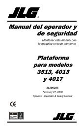
Illustration 18<br />
Engine view of a turbocharged aftercooled engine<br />
g01430279
SEBU8180-01 21<br />
Product Information Section<br />
Model Views<br />
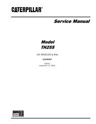
Illustration 19<br />
Engine view of a turbocharged engine<br />
Front left engine view<br />
(1) Front lifting eye<br />
(2) Water outlet<br />
(3) Rear lifting eye<br />
(4) Fuel manifold (rail)<br />
(5) Electronic control module<br />
(6) Secondary fuel filter<br />
(7) Water pump<br />
(8) Oil Filler<br />
(9) Oil gauge<br />
(10) Oil sampling valve<br />
(11) Oil filter<br />
(12) Crankshaft pulley<br />
(13) Drive Belt<br />
(14) Belt tensioner<br />
g01430281
22 SEBU8180-01<br />
Product Information Section<br />
Model Views<br />
Illustration 20<br />
Rear right engine view<br />
(15) Alternator<br />
(16) Exhaust manifold<br />
(17) Turbocharger<br />
(18) Wastegate solenoid<br />
Note: The primary fuel filter may be mounted off the<br />
engine.<br />
Engine Description<br />
SMCS Code: 1000<br />
The Caterpillar C-4.4 Industrial Engine has the<br />
following characteristics:<br />
• In-Line4cylinder<br />
• Four stroke cycle<br />
• Turbocharged<br />
• Turbocharged aftercooled<br />
(19) Drain plug or coolant sampling valve<br />
(20) Starting Motor<br />
(21) Oil drain plug<br />
(22) Primary fuel filter<br />
i02872108<br />
(23) H<strong>and</strong> fuel priming pump<br />
(24) Flywheel<br />
(25) Flywheel housing<br />
Engine Specifications<br />
g01430282<br />
Note: The front end of the engine is opposite the<br />
flywheel end of the engine. The left <strong>and</strong> the right<br />
sides of the engine are determined from the flywheel<br />
end. The number 1 cylinder is the front cylinder.
SEBU8180-01 23<br />
Product Information Section<br />
Model Views<br />
• Engine monitoring<br />
• Engine speed governing<br />
• Control of injection pressure<br />
• Cold start strategy<br />
• Automatic air/fuel ratio control<br />
• Torque rise shaping<br />
• Injection timing control<br />
• System diagnostics<br />
For more information on electronic engine features,<br />
refer to the <strong>Operation</strong> <strong>and</strong> <strong>Maintenance</strong> <strong>Manual</strong>,<br />
“Engine Features <strong>and</strong> Controls” topic (<strong>Operation</strong><br />
Section).<br />
Illustration 21<br />
(A) Exhaust valve<br />
(B) Inlet valve<br />
Table 1<br />
C-4.4EngineSpecifications<br />
Operating Range (rpm) 700 to 2640 (1)<br />
Arrangement <strong>and</strong><br />
Cylinders<br />
Bore<br />
Stroke<br />
Aspiration<br />
In-Line 4 cylinder<br />
105 mm (4.13 inch)<br />
127 mm (5 inch)<br />
g01187485<br />
Turbocharged,<br />
Turbocharged aftercooled<br />
Compression Ratio 16.2:1<br />
Displacement 4.4 L (269 in 3 )<br />
Firing Order 1-3-4-2<br />
Rotation (flywheel end)<br />
Valve Lash (inlet)<br />
Valve Lash (exhaust)<br />
Counterclockwise<br />
0.35 mm (0.013 inch)<br />
0.35 mm (0.013 inch)<br />
(1) The operating rpm is dependent on the engine rating, the<br />
application <strong>and</strong> the configuration of the throttle.<br />
Electronic Engine Features<br />
The Caterpillar C-4.4 Engine is designed for<br />
electronic controls. The integral on board computer<br />
controls the operation of the engine. Current<br />
operating conditions are monitored. The Electronic<br />
Control Module (ECM) controls the response of the<br />
engine to these conditions <strong>and</strong> to the dem<strong>and</strong>s of the<br />
operator. These conditions <strong>and</strong> operator dem<strong>and</strong>s<br />
determine the precise control of fuel injection by the<br />
ECM. The electronic engine control system provides<br />
the following features:<br />
Engine Diagnostics<br />
The engine has built-in diagnostics in order to ensure<br />
that the engine systems are functioning correctly.<br />
The operator will be informed of any change to a<br />
programmed limit. The operator will be alerted to<br />
the condition by a “Stop or Warning” lamp that is<br />
mounted on the dashboard. Under certain conditions,<br />
the engine horsepower <strong>and</strong> the vehicle speed may<br />
be limited. The Caterpillar Electronic Technician (ET)<br />
maybeusedtodisplaythediagnosticcodes.<br />
There are three types of codes: active diagnostic,<br />
logged diagnostic, <strong>and</strong> event.<br />
Most of the diagnostic codes are logged <strong>and</strong> stored<br />
in the ECM. For additional information, refer to<br />
the <strong>Operation</strong> <strong>and</strong> <strong>Maintenance</strong> <strong>Manual</strong>, “Engine<br />
Diagnostics” topic (<strong>Operation</strong> Section).<br />
The ECM provides an electronic governor that<br />
controls the injector output in order to maintain the<br />
desired engine rpm.<br />
Engine Cooling <strong>and</strong> Lubrication<br />
The cooling system consists of the following<br />
components:<br />
• Gear-driven centrifugal water pump<br />
• Water temperature regulator which regulates the<br />
engine coolant temperature<br />
• Gear-driven oil pump<br />
• Oil cooler
24 SEBU8180-01<br />
Product Information Section<br />
Model Views<br />
The engine lubricating oil is supplied by a rotor type<br />
oil pump. The engine lubricating oil is cooled <strong>and</strong> the<br />
engine lubricating oil is filtered. The bypass valves<br />
can provide unrestricted flow of lubrication oil to<br />
the engine if the oil filter element should become<br />
plugged.<br />
Engine efficiency, efficiency of emission controls, <strong>and</strong><br />
engine performance depend on adherence to proper<br />
operation <strong>and</strong> maintenance recommendations.<br />
Engine performance <strong>and</strong> efficiency also depend on<br />
the use of recommended fuels, lubrication oils, <strong>and</strong><br />
coolants. Refer to this <strong>Operation</strong> <strong>and</strong> <strong>Maintenance</strong><br />
<strong>Manual</strong>, “<strong>Maintenance</strong> Interval Schedule” for more<br />
information on maintenance items.<br />
Engine Service Life<br />
Engine efficiency <strong>and</strong> maximum utilization of engine<br />
performance depend on the adherence to proper<br />
operation <strong>and</strong> maintenance recommendations. In<br />
addition, use recommended fuels, coolants <strong>and</strong><br />
lubricants. Use the <strong>Operation</strong> <strong>and</strong> <strong>Maintenance</strong><br />
<strong>Manual</strong> as a guide for required engine maintenance.<br />
Expected engine life is generally predicted by the<br />
average power that is dem<strong>and</strong>ed. The average power<br />
that is dem<strong>and</strong>ed is based on fuel consumption of<br />
the engine over a period of time. Reduced hours of<br />
operation at full throttle <strong>and</strong>/or operating at reduced<br />
throttle settings result in a lower average power<br />
dem<strong>and</strong>. Reduced hours of operation will increase<br />
the length of operating time before an engine<br />
overhaul is required. For more information, refer to<br />
the <strong>Operation</strong> <strong>and</strong> <strong>Maintenance</strong> <strong>Manual</strong>, “Overhaul<br />
Considerations” topic (<strong>Maintenance</strong> Section).<br />
Aftermarket Products <strong>and</strong><br />
Caterpillar Engines<br />
When auxiliary devices, accessories, or consumables<br />
(filters, additives, catalysts, etc) which are made<br />
by other manufacturers are used on Caterpillar<br />
products, the Caterpillar warranty is not affected<br />
simply because of such use.<br />
Welding <strong>and</strong> Caterpillar Electronic<br />
Engines<br />
NOTICE<br />
Because the strength of the frame may decrease,<br />
some manufacturers do not recommend welding onto<br />
a chassis frame or rail. Consult the OEM of the equipment<br />
or your Caterpillar dealer regarding welding on<br />
a chassis frame or rail.<br />
To help avoid damage to the electronic controls,<br />
proper welding procedures are necessary. Before<br />
welding on an engine that is equipped with an<br />
electronic engine, observe the following precautions:<br />
1. Turn off the engine. Place the key start switch in<br />
the OFF position.<br />
2. If the machine has a battery disconnect switch,<br />
open the switch. Otherwise, disconnect the<br />
negative “-” battery cable from the battery of the<br />
vehicle.<br />
NOTICE<br />
Do not ground the welder to electrical components<br />
such as the ECM or sensors. Improper grounding can<br />
cause damage to the drive train bearings, hydraulic<br />
components, electrical components, <strong>and</strong> other components.<br />
Clamp the ground cable from the welder to the component<br />
that will be welded. Place the clamp as close<br />
as possible to the weld. This will help reduce the possibility<br />
of damage.<br />
3. Clamp the ground cable from the welder to the<br />
component that will be welded. Place the clamp<br />
as close as possible to the weld.<br />
4. Protect wiring harnesses from welding debris <strong>and</strong><br />
spatter. Use proper welding procedures.<br />
However, failures that result from the installation<br />
or use of other manufacturers’ devices,<br />
accessories, or consumables are NOT Caterpillar<br />
defects. Therefore, the defects are NOT covered<br />
under the Caterpillar warranty.
SEBU8180-01 25<br />
Product Information Section<br />
Product Identification Information<br />
Product Identification<br />
Information<br />
Plate Locations <strong>and</strong> Film<br />
Locations<br />
i02499733<br />
SMCS Code: 1000<br />
Illustration 23<br />
Serial number plate<br />
g01258789<br />
Reference Numbers<br />
i00610276<br />
SMCS Code: 1000<br />
Information for the following items may be needed to<br />
order parts. Locate the information for your engine.<br />
Record the information on the appropriate space.<br />
Make a copy of this list for a record. Retain the<br />
information for future reference.<br />
Record for Reference<br />
Engine Model _______________________________________________<br />
Engine Serial No. __________________________________________<br />
Engine Arrangement No. _________________________________<br />
Illustration 22<br />
Location of the serial number plate<br />
Serial Number Plate (1)<br />
g01248563<br />
Modification No. ____________________________________________<br />
Engine Low Idle rpm ______________________________________<br />
Engine Full Load rpm _____________________________________<br />
Theengineserialnumberplateislocatedontheleft<br />
side of the cylinder block to the rear of the engine.<br />
Caterpiller dealers need all of these numbers in order<br />
to determine the components that were included with<br />
the engine. This permits accurate identification of<br />
replacement part numbers.<br />
Performance Specification No. _________________________<br />
Primary Fuel Filter No. ____________________________________<br />
Water Separator Element No. ___________________________<br />
Secondary Fuel Filter Element No. ____________________<br />
Lubrication Oil Filter Element No. ______________________<br />
Auxiliary Oil Filter Element No. _________________________<br />
Supplemental Coolant Additive <strong>Maintenance</strong> Element<br />
No. (Optional) _______________________________________________<br />
Total Lubrication System Capacity _____________________
26 SEBU8180-01<br />
Product Information Section<br />
Product Identification Information<br />
Total Cooling System Capacity _________________________<br />
Air Cleaner Element No. _________________________________<br />
Fan Drive Belt No. _________________________________________<br />
Alternator Belt No. _________________________________________<br />
i02894858<br />
Emissions Certification Film<br />
SMCS Code: 1000; 7405<br />
This information is pertinent in the United States <strong>and</strong><br />
in Canada.<br />
Illustration 24<br />
Typical example<br />
g01440937<br />
Customer Specified<br />
Parameters<br />
SMCS Code: 1000<br />
To record programmed specifications, use the<br />
following blanks.<br />
Customer Passwords<br />
i02238153<br />
• First Password ___________________________________________<br />
• Second Password ______________________________________<br />
Power Rating (hp at rpm) ______________________________<br />
Rating Selection (A-E) __________________________________<br />
PTO Governor Parameters<br />
• PTO Engine Speed Ramp Rate __________ rpm/sec<br />
Engine Parameters<br />
• Top Engine Limit (TEL) at 100 percent load (If<br />
Applicable) _______________________________________________<br />
• Torque Limit ______________________________________________<br />
• High Idle (If Applicable) ________________________________<br />
• Low Idle ___________________________________________________<br />
• Intermediate Speed ____________________________________<br />
Engine Monitoring Mode<br />
• “OFF” ______________________________________________________
SEBU8180-01 27<br />
Product Information Section<br />
Product Identification Information<br />
• “Warning” _________________________________________________<br />
• “Warning/Derate” ________________________________________<br />
• “Warning/Derate/Shutdown” __________________________<br />
• “Coolant Level Sensor Enable/Disable” ____________<br />
• “Fuel Pressure Sensor Enable/Disable” ___________<br />
• “Inlet Manifold Air Temperature Sensor<br />
Enable/Disable” _________________________________________<br />
Equipment ID<br />
<strong>Maintenance</strong> Indicator<br />
• <strong>Manual</strong>-Hours<br />
• Auto-Hours<br />
• <strong>Manual</strong>-Fuel<br />
• Auto-Fuel<br />
Auxiliary Pressure<br />
• High Warning Set Point ________________________________<br />
Auxiliary Temperature<br />
• High Warning Set Point ________________________________
28 SEBU8180-01<br />
<strong>Operation</strong> Section<br />
Lifting <strong>and</strong> Storage<br />
<strong>Operation</strong> Section<br />
Lifting <strong>and</strong> Storage<br />
Product Lifting<br />
SMCS Code: 1000; 1404; 7002<br />
i02437864<br />
Product Storage<br />
SMCS Code: 1000; 1404; 7002<br />
i02068367<br />
If the engine will not be started for several weeks, the<br />
lubricating oil will drain from the cylinder walls <strong>and</strong><br />
from the piston rings. Rust can form on the cylinder<br />
liner surface. Rust on the cylinder liner surface will<br />
cause increased engine wear <strong>and</strong> a reduction in<br />
engine service life.<br />
To help prevent excessive engine wear, use the<br />
following guidelines:<br />
• Complete all of the lubrication recommendations<br />
that are listed in this <strong>Operation</strong> <strong>and</strong> <strong>Maintenance</strong><br />
<strong>Manual</strong>, “<strong>Maintenance</strong> Interval Schedule”<br />
(<strong>Maintenance</strong> Section).<br />
• If freezing temperatures are expected, check the<br />
cooling system for adequate protection against<br />
freezing. See this <strong>Operation</strong> <strong>and</strong> <strong>Maintenance</strong><br />
<strong>Manual</strong>, “Refill Capacities <strong>and</strong> Recommendations”<br />
(<strong>Maintenance</strong> Section).<br />
Illustration 25<br />
g00103219<br />
NOTICE<br />
Never bend the eyebolts <strong>and</strong> the brackets. Only load<br />
the eyebolts <strong>and</strong> the brackets under tension. Remember<br />
that the capacity of an eyebolt is less as the angle<br />
between the supporting members <strong>and</strong> the object becomes<br />
less than 90 degrees.<br />
When it is necessary to remove a component at an<br />
angle, only use a link bracket that is properly rated for<br />
the weight.<br />
If an engine is out of operation <strong>and</strong> if use of the engine<br />
is not planned, special precautions should be made.<br />
If the engine will be stored for more than one month,<br />
a complete protection procedure is recommended.<br />
For more detailed information on engine storage, see<br />
Special Instruction, SEHS9031, “Storage Procedure<br />
For Caterpillar Products”.<br />
Your Caterpillar dealer can assist in preparing the<br />
engine for extended storage periods.<br />
Use a hoist to remove heavy components. Use<br />
an adjustable lifting beam to lift the engine. All<br />
supporting members (chains <strong>and</strong> cables) should be<br />
parallel to each other. The chains <strong>and</strong> cables should<br />
be perpendicular to the top of the object that is being<br />
lifted.<br />
Some removals require lifting the fixtures in order to<br />
obtain proper balance <strong>and</strong> safety.<br />
ToremovetheengineONLY,usetheliftingeyesthat<br />
are on the engine.<br />
Lifting eyes are designed <strong>and</strong> installed for the specific<br />
engine arrangement. Alterations to the lifting eyes<br />
<strong>and</strong>/or the engine make the lifting eyes <strong>and</strong> the lifting<br />
fixtures obsolete. If alterations are made, ensure<br />
that proper lifting devices are provided. Consult your<br />
Caterpillar dealer for information regarding fixtures<br />
for proper engine lifting.
SEBU8180-01 29<br />
<strong>Operation</strong> Section<br />
Gauges <strong>and</strong> Indicators<br />
Gauges <strong>and</strong> Indicators<br />
Gauges <strong>and</strong> Indicators<br />
SMCS Code: 1900; 7450<br />
i02724238<br />
Your engine may not have the same gauges or all of<br />
the gauges that are described. For more information<br />
about the gauge package, see the OEM information.<br />
Gauges provide indications of engine performance.<br />
Ensure that the gauges are in good working order.<br />
Determine the normal operating range by observing<br />
the gauges over a period of time.<br />
Noticeable changes in gauge readings indicate<br />
potential gauge or engine problems. Problems may<br />
also be indicated by gauge readings that change<br />
even if the readings are within specifications.<br />
Determine <strong>and</strong> correct the cause of any significant<br />
change in the readings. Consult your Caterpillar<br />
dealer for assistance.<br />
Some engine applications are equipped with Indicator<br />
Lamps. Indicator lamps can be used as a diagnostic<br />
aid. There are two lamps. One lamp has an orange<br />
lens <strong>and</strong> the other lamp has a red lens.<br />
These indicator lamps can be used in two ways:<br />
• The indicatorlampscanbeusedtoidentifythe<br />
current operational status of the engine. The<br />
indicator lamps can also indicate that the engine<br />
has a fault. This system is automatically operated<br />
via the ignition switch.<br />
• The indicator lamps can be used to identify active<br />
diagnostic codes. This system is activated by<br />
pressing the Flash Code button.<br />
Refer to the Troubleshooting Guide, “Indicator<br />
Lamps” for further information.<br />
NOTICE<br />
If no oil pressure is indicated, STOP the engine. If<br />
maximum coolant temperature is exceeded, STOP<br />
the engine. Engine damage can result.<br />
Engine Oil Pressure – The oil pressure<br />
should be greatest after a cold engine is<br />
started. The typical engine oil pressure with<br />
SAE10W40is350to450kPa(50to65psi)atrated<br />
rpm.<br />
A lower oil pressure is normal at low idle. If the load<br />
is stable <strong>and</strong> the gauge reading changes, perform<br />
the following procedure:<br />
1. Remove the load.<br />
2. Stop the engine.<br />
3. Check <strong>and</strong> maintain the oil level.<br />
Jacket Water Coolant Temperature –<br />
Typical temperature range is 83° to 95°C<br />
(181.4° to 171°F). The maximum allowable<br />
temperature at sea level with the pressurized cooling<br />
system at 48 kPa (7 psi) is 103 °C (217.4 °F). Higher<br />
temperatures may occur under certain conditions.<br />
The water temperature reading may vary according<br />
to load. The temperature reading should never<br />
exceed 7 °C (44.6 °F) below the boiling point for the<br />
pressurized system that is being used.<br />
A 100 kPa (14.5 psi) radiator cap may be installed on<br />
the cooling system. The temperature of this cooling<br />
system must not exceed 112 °C (233.6 °F).<br />
If the engine is operating above the normal range<br />
<strong>and</strong> steam becomes apparent, perform the following<br />
procedure:<br />
1. Reduce the load <strong>and</strong> the engine rpm.<br />
2. Determine if the engine must be shut down<br />
immediately or if the engine can be cooled by<br />
reducing the load.<br />
3. Inspect the cooling system for leaks.<br />
Tachometer – This gauge indicates engine<br />
speed (rpm). When the throttle control lever<br />
ismovedtothefullthrottlepositionwithout<br />
load, the engine is running at high idle. The engine is<br />
running at thefullloadrpmwhenthethrottlecontrol<br />
lever is at the full throttle position with maximum<br />
rated load.<br />
NOTICE<br />
To help prevent engine damage, never exceed the<br />
high idle rpm. Overspeeding can result in serious<br />
damage to the engine. <strong>Operation</strong> at speeds exceeding<br />
high idle rpm should be kept to a minimum.<br />
Ammeter – This gauge indicates the<br />
amount of charge or discharge in the<br />
battery charging circuit. <strong>Operation</strong> of the<br />
indicator should be to the “+” side of “0” (zero).<br />
Fuel Level – This gauge indicates the fuel<br />
level in the fuel tank. The fuel level gauge<br />
operates when the “START/STOP” switch<br />
is in the “on” position.
30 SEBU8180-01<br />
<strong>Operation</strong> Section<br />
Gauges <strong>and</strong> Indicators<br />
Service Hour Meter – The gauge indicates<br />
total operating hours of the engine.
SEBU8180-01 31<br />
<strong>Operation</strong> Section<br />
Features <strong>and</strong> Controls<br />
Features <strong>and</strong> Controls<br />
Monitoring System<br />
i02330192<br />
SMCS Code: 1900; 7400; 7402; 7450; 7451<br />
Table 2<br />
Warning<br />
Lamp<br />
ON<br />
OFF<br />
ON<br />
ON<br />
FLASHING<br />
FLASHING<br />
ON<br />
Shutdown<br />
Lamp<br />
ON<br />
OFF<br />
OFF<br />
FLASHING<br />
OFF<br />
FLASHING<br />
ON<br />
Lamp Status Description of lamp status Engine Status<br />
Lamp check<br />
When the engine start switch is turned to the<br />
“ON” position both lamps will illuminate for 2<br />
seconds only.<br />
The engine has not been<br />
started.<br />
No faults There are no active diagnostic faults. Theengineisrunning<br />
normally.<br />
Active<br />
diagnostic<br />
fault<br />
Active<br />
diagnostic<br />
fault<br />
Warning<br />
Derate <strong>and</strong><br />
warning<br />
Engine<br />
shutdown<br />
An active diagnostic fault has been detected.<br />
A serious active diagnostic fault has been<br />
detected <strong>and</strong> an engine derate has been<br />
invoked.<br />
One or more of the engine protection values<br />
has been exceeded.<br />
One or more of the engine protection values<br />
has been exceeded.<br />
One or more of the engine protection values has<br />
been exceeded or a serious active diagnostic<br />
fault has been detected.<br />
The engine is running<br />
normally.<br />
Theengineisrunning<br />
but the engine has been<br />
derated.<br />
Theengineis running<br />
normally.<br />
Theengineisrunning<br />
but the engine has been<br />
derated.<br />
The engine is shutdown or<br />
shutdown is imminent.<br />
Monitoring System<br />
SMCS Code: 1900; 7400; 7402; 7450; 7451<br />
i02724323<br />
• Coolant temperature<br />
• Intake manifold air temperature<br />
• Intake manifold air pressure<br />
• Oil pressure<br />
If the Shutdown mode has been selected <strong>and</strong> the<br />
warning indicator activates, engine shutdown may<br />
take as little as 20 seconds from the time the warning<br />
indicator is activated. Depending on the application,<br />
special precautions should be taken to<br />
avoid personal injury. The engine can be restarted<br />
following shutdown for emergency maneuvers, if<br />
necessary.<br />
• Pressure in the fuel rail<br />
• Engine speed/timing<br />
Programmable Options <strong>and</strong><br />
Systems <strong>Operation</strong><br />
NOTICE<br />
The Engine Monitoring System is not a guarantee<br />
against catastrophic failures. Programmed delays<br />
<strong>and</strong> derate schedules are designed to minimize false<br />
alarms <strong>and</strong> provide time for the operator to stop the<br />
engine.<br />
If the Warning/Derate/Shutdown mode has been<br />
selected <strong>and</strong> the warning indicator activates,<br />
bring the engine to a stop whenever possible. Depending<br />
on the application, special precautions<br />
should be taken to avoid personal injury.<br />
The following parameters are monitored:
32 SEBU8180-01<br />
<strong>Operation</strong> Section<br />
Features <strong>and</strong> Controls<br />
Theenginecanbe programmed to the following<br />
modes:<br />
“Warning”<br />
Sensors <strong>and</strong> Electrical<br />
Components<br />
i02861773<br />
The “Warning” lamp <strong>and</strong> the warning signal (orange<br />
lamp) turn “ON” <strong>and</strong> the warning signal is activated<br />
continuously in order to alert the operator that one or<br />
more of the engine parameters is not within normal<br />
operating range.<br />
“Warning/Derate”<br />
The “Diagnostic” lamp turns “ON” <strong>and</strong> the warning<br />
signal (red lamp) is activated. After the warning, the<br />
engine power will be derated. The warning lamp will<br />
begin to flash when the derating occurs.<br />
SMCS Code: 1900; 7400<br />
Sensor Locations<br />
Illustration 26 shows the typical locations of the<br />
sensors <strong>and</strong> the ECM on the engine. Specific engines<br />
may appear different from the illustration due to<br />
differences in applications.<br />
The engine will be derated if the engine exceeds<br />
preset operational limits. The engine derate is<br />
achieved by restricting the amount of fuel that is<br />
available for each injection. The amount of this<br />
reduction of fuel is dependent on the severity of the<br />
fault that has caused the engine derate, typically up<br />
to a limit of 50%. This reduction in fuel results in a<br />
predetermined reduction in engine power.<br />
“Warning/Derate/Shutdown”<br />
The “Diagnostic” lamp turns “ON” <strong>and</strong> the warning<br />
signal (red lamp) is activated. After the warning,<br />
the engine power will be derated. The engine will<br />
continue at the rpm of the set derate until a shutdown<br />
of the engine occurs. The engine can be restarted<br />
after a shutdown for use in an emergency.<br />
Ashutdown of the engine may occur in as little<br />
as 20 seconds. The engine can be restarted after<br />
ashutdownforuseinanemergency.However,<br />
the cause of the initial shutdown may still exist.<br />
The engine may shut down again in as little as 20<br />
seconds.<br />
If there is a signal for low oil pressure or for coolant<br />
temperature, there will be a two second delay in<br />
order to verify the condition.<br />
For each of the programmed modes, refer to<br />
Troubleshooting Guide, “Indicator Lamps” for more<br />
information on Indicator Lamps.<br />
For more information or assistance for repairs,<br />
consult your Caterpillar dealer.
SEBU8180-01 33<br />
<strong>Operation</strong> Section<br />
Features <strong>and</strong> Controls<br />
Illustration 26<br />
(1) Coolant temperature sensor<br />
(2) Intake manifold pressure sensor<br />
(3) Inlet air temperature sensor<br />
(4) Fuel pressure sensor<br />
(5) Electronic control module<br />
(6) Primary position sensor<br />
(7) Secondary position sensor<br />
(8) Engine oil pressure sensor<br />
g01425443<br />
Illustration 27 shows the sensors <strong>and</strong> the ECM in<br />
position on the engine.
34 SEBU8180-01<br />
<strong>Operation</strong> Section<br />
Features <strong>and</strong> Controls<br />
Illustration 27<br />
Failure of Sensors<br />
All Sensors<br />
A failure of any of the sensors may be caused by one<br />
of the following malfunctions:<br />
• Sensor output is open.<br />
• Sensor output is shorted to “- battery” or “+ battery”.<br />
• Measured reading of the sensor is out of the<br />
specification.<br />
g01425468<br />
Programmable Monitoring System<br />
(PMS)<br />
The Programmable Monitoring System determines<br />
the level of action that is taken by the Electronic<br />
Control Module (ECM) in response to a condition<br />
that can damage the engine. These conditions are<br />
identified by the ECM from the signals that are<br />
produced from the following sensors.<br />
• Coolant Temperature Sensor<br />
• Intake manifold Air Temperature Sensor<br />
• Intake manifold Pressure Sensor<br />
• Fuel Pressure Sensor
SEBU8180-01 35<br />
<strong>Operation</strong> Section<br />
Features <strong>and</strong> Controls<br />
• Engine Oil Pressure Sensor<br />
• Primary Speed/Timing Sensor<br />
• Secondary Speed/Timing Sensor<br />
Coolant Temperature Sensor 1<br />
The coolant temperature sensor monitors engine<br />
coolant temperature. The output of the ECM (5) can<br />
indicate a high coolant temperature through a relay<br />
or a lamp. The coolant temperature sensor is used<br />
by the ECM to determine initiation of the Cold Start<br />
Condition.<br />
Failure of the Coolant Temperature<br />
Sensor<br />
The ECM (5) will detect a failure of the coolant<br />
temperature sensor. The diagnostic lamp will warn the<br />
operator about the status of the coolant temperature<br />
sensor. A failure of the coolant temperature sensor<br />
will not cause a shutdown of the engine or any<br />
horsepower change. In order to check the correct<br />
operation of the sensor, refer to Troubleshooting,<br />
“Engine Temperature Sensor Circuit - Test”.<br />
Intake Manifold Air Temperature<br />
Sensor 2<br />
Note: This sensor can have two different locations.<br />
The location will depend on the type of engine.<br />
The intake manifold air temperature sensor measures<br />
the intake air temperature. A signal is sent to the<br />
ECM (5). The intake manifold air temperature sensor<br />
is also used by the ECM to determine initiation of the<br />
Cold Start Strategy.<br />
In order to check the correct operation of the sensor,<br />
refer to Troubleshooting, “EngineTemperature Sensor<br />
Circuit - Test”.<br />
Intake Manifold Pressure Sensor 3<br />
The intake manifold pressure sensor measures<br />
pressure in the manifold. A signal is sent to the ECM<br />
(5).<br />
Fuel Pressure Sensor 4<br />
The fuel pressure sensor measures the fuel pressure<br />
in the fuel manifold. A signal is sent to the ECM (5).<br />
Electronic Control Module 5<br />
The ECM is the control computer of the engine. The<br />
ECM provides power to the electronics. The ECM<br />
monitors data that is input from the sensors of the<br />
engine. The ECM acts as a governor in order to<br />
control the speed <strong>and</strong> the power of the engine.<br />
The ECM adjusts injection timing <strong>and</strong> fuel pressure<br />
for the best engine performance, the best fuel<br />
economy <strong>and</strong> the best control of exhaust emissions.<br />
Primary Speed/Timing Sensor 6<br />
If the ECM (5) does not receive a signal from the<br />
primary speed/timing sensor , the “DIAGNOSTIC”<br />
lamp will indicate a diagnostic fault code which will be<br />
logged in the ECM memory.<br />
If the ECM does not receive a signal from the primary<br />
speed/timing sensor (7), the ECM will read the signal<br />
from the secondary speed/timing sensor (8). The<br />
ECM continually checks in order to determine if there<br />
is a signal from both sensors.<br />
Intermittent failure of the sensors will cause erratic<br />
engine control.<br />
Failure of the Primary Speed/Timing<br />
Sensor<br />
Correct operation of the primary speed/timing<br />
sensor is essential. Software in the ECM protects<br />
against reverse running of the engine. If the primary<br />
speed/timing sensor fails there is no automatic<br />
protection against reverse running. In some<br />
applications, it is possible for the transmission to<br />
run the engine in reverse. In this event, Stop the<br />
engineimmediately.Turnthekeyswitchtothe“OFF”<br />
position.<br />
In order to check the correct operation of the sensor,<br />
refer to Troubleshooting, “Engine speed/Timing<br />
sensor - Test”.<br />
Secondary Speed/Timing Sensor 7<br />
The signal from the secondary speed/timing sensor<br />
is used by the ECM (5) on engine start-up in order<br />
to check the stroke of the pistons. The secondary<br />
speed/timing sensor may be used by the ECM<br />
in order to operate the engine if the primary<br />
speed/timing sensor is faulty.<br />
In order to check the correct operation of the sensor,<br />
refer to Troubleshooting, “Engine speed/Timing<br />
sensor-Test”.
36 SEBU8180-01<br />
<strong>Operation</strong> Section<br />
Features <strong>and</strong> Controls<br />
Engine Oil Pressure Sensor 8<br />
Note: This sensor can have two different locations.<br />
The location will depend on the type of engine.<br />
The engine oil pressure sensor is an absolute<br />
pressure sensor that measures the engine oil<br />
pressure in the main oil gallery. The engine oil<br />
pressure sensor detects engine oil pressure for<br />
diagnostic purposes. The engine oil pressure sensor<br />
sends a signal to the ECM (5).<br />
Low Oil Pressure Warning<br />
The setpoint for the low pressure warning is<br />
dependent upon the engine speed. The fault will be<br />
active <strong>and</strong> logged only if the engine has been running<br />
for more than 8 seconds.<br />
Very Low Oil Pressure Warning<br />
The very low oil pressure setpoint is dependent<br />
upon the engine speed. If the DERATE mode of the<br />
engine monitoring system is selected, the ECM (5)<br />
will derate the engine power. The engine horsepower<br />
will be limited.<br />
Failure of the Engine Oil Pressure Sensor<br />
The ECM (5) will detect failure of the engine oil<br />
pressure sensor. The diagnostic lamp warns the user<br />
about the status of the engine oil pressure sensor.<br />
The engine oil pressure related strategies will be<br />
disabled in the event of a failure of the engine oil<br />
pressure sensor. A failure of the engine oil pressure<br />
sensor will not cause a shutdown of the engine or<br />
any horsepower change. In order to check the correct<br />
operation of the sensor, refer to Troubleshooting, “5<br />
Volt Sensor Supply Circuit - Test”.<br />
i02858345<br />
Engine Shutoffs <strong>and</strong> Engine<br />
Alarms<br />
SMCS Code: 1900; 7400; 7418<br />
Shutoffs<br />
The shutoffs are electrically operated or mechanically<br />
operated. The electrically operated shutoffs are<br />
controlled by the ECM.<br />
Shutoffs are set at critical levels for the following<br />
items:<br />
• Operating temperature<br />
• Operating level<br />
• Operating rpm<br />
The particular shutoff may need to be reset before<br />
theenginewillstart.<br />
NOTICE<br />
Always determine the cause of the engine shutdown.<br />
Make necessary repairs before attempting to restart<br />
the engine.<br />
Be familiar with the following items:<br />
• Types <strong>and</strong> locations of shutoff<br />
• Conditions which cause each shutoff to function<br />
• The resetting procedure that is required to restart<br />
the engine<br />
Alarms<br />
The alarms are electrically operated. The operation<br />
of the alarms are controlled by the ECM.<br />
The alarm is operated by a sensor or by a switch.<br />
When the sensor or the switch is activated a signal<br />
is sent to the ECM. An event code is created by<br />
the ECM. The ECM will send a signal in order to<br />
illuminate the lamp.<br />
Your engine may be equipped with the following<br />
sensors or switches:<br />
Coolant level – The low coolant level switch<br />
indicates when the coolant level is low.<br />
Coolant temperature – The coolant temperature<br />
sensor indicates high jacket water coolant<br />
temperature.<br />
Intake manifold air temperature – The intake<br />
manifold air temperature sensor indicates high intake<br />
air temperature.<br />
Intake manifold pressure – The intake manifold<br />
pressure sensor checks the rated pressure in the<br />
engine manifold.<br />
Fuel rail pressure – The fuel rail pressure sensor<br />
checks for high pressure or low pressure in the fuel<br />
rail.<br />
Engine oil pressure –The engine oil pressure<br />
sensor indicates when oil pressure drops below rated<br />
system pressure, at a set engine speed.<br />
• Operating pressure
SEBU8180-01 37<br />
<strong>Operation</strong> Section<br />
Features <strong>and</strong> Controls<br />
Engine overspeed – The primary speed/timing<br />
sensor checks the engine speed. The alarm is<br />
activated at 3000 RPM.<br />
Air filter restriction – The switch checks the air<br />
filter when the engine is operating.<br />
User defined switch – This switch can shut down<br />
the engine remotely.<br />
Water in fuel switch – This switch checks for water<br />
in the primary fuel filter when the engine is operating.<br />
Note: The sensing element of the coolant<br />
temperature switch must be submerged in coolant<br />
in order to operate.<br />
Engines may be equipped with alarms in order<br />
to alert the operator when undesirable operating<br />
conditions occur.<br />
NOTICE<br />
When an alarm is activated, corrective measures must<br />
be taken before the situation becomes an emergency<br />
in order to avoid possible engine damage.<br />
If corrective measures are not taken within a<br />
reasonable time, engine damage could result. The<br />
alarm will continue until the condition is corrected.<br />
The alarm may needtobereset.<br />
Testing<br />
Turning the keyswitch to the ON position will check<br />
the indicator lights on the control panel. All the<br />
indicator lights will be illuminated for two seconds<br />
after the keyswitch is operated. Replace suspect<br />
bulbs immediately.<br />
Refer to Troubleshooting for more information.<br />
Overspeed<br />
i02254118<br />
SMCS Code: 1900; 1907; 1912; 7427<br />
An overspeed condition is detected by the Electronic<br />
Control Module (ECM). The event code E0190 will be<br />
logged if the engine speed exceeds 3300 rpm. The<br />
“DIAGNOSTIC” lamp will indicate a diagnostic fault<br />
code. The diagnostic fault code will remain active<br />
until the engine speed drops to 2800 rpm.
38 SEBU8180-01<br />
<strong>Operation</strong> Section<br />
Engine Diagnostics<br />
Engine Diagnostics<br />
Self-Diagnostics<br />
SMCS Code: 1000; 1900; 1901; 1902<br />
i01796959<br />
Caterpillar Electronic Engines have the capability to<br />
perform a self-diagnostics test. When the system<br />
detects an active problem, a diagnostic lamp<br />
is activated. Diagnostic codes will be stored in<br />
permanent memory in the Electronic Control Module<br />
(ECM). The diagnostic codes can be retrieved by<br />
using Caterpillar electronic service tools.<br />
Some installations have electronic displays that<br />
provide direct readouts of the engine diagnostic<br />
codes. Refer to the manual that is provided by the<br />
OEM for more information on retrieving engine<br />
diagnostic codes.<br />
Active codes represent problems that currently exist.<br />
These problems should be investigated first.<br />
Logged codes represent the following items:<br />
• Intermittent problems<br />
• Recorded events<br />
• Performance history<br />
The problems may have been repaired since the<br />
logging of the code. These codes do not indicate that<br />
a repair is needed. The codes are guides or signals<br />
when a situation exists. Codes may be helpful to<br />
troubleshoot problems.<br />
When the problems have been corrected, the<br />
corresponding logged fault codes should be cleared.<br />
Diagnostic Lamp<br />
SMCS Code: 1000; 1900; 1901; 1902; 7451<br />
i02501517<br />
A diagnostic lamp is used to indicate the existence<br />
of an active fault. A fault diagnostic code will remain<br />
active until the problem is repaired. The diagnostic<br />
code may be retrieved by using Caterpillar electronic<br />
technician (ET).<br />
Diagnostic Flash Code<br />
Retrieval<br />
SMCS Code: 1000; 1900; 1901; 1902<br />
“Diagnostic” Lamp<br />
i02872126<br />
Use the “DIAGNOSTIC” Lamp or an electronic<br />
service tool to determine the diagnostic flash code.<br />
Usethefollowingproceduretoretrievetheflash<br />
codes if the engine is equipped with a “DIAGNOSTIC”<br />
lamp:<br />
1. Turn the keyswitch “ON/OFF” two times within 3<br />
seconds.<br />
A flashing“YELLOW” lamp indicates a 3 digit code for<br />
the engine. The sequence of flashes represents the<br />
system diagnostic message. Count the first sequence<br />
of flashes in order to determine the first digit of the<br />
flash code. After a two second pause, the second<br />
sequence of flashes will identify the second digit of<br />
the flash code. After the second pause, the third<br />
sequence of flashes will identify the flash code.<br />
Any additional flash codes will follow after a pause.<br />
These codes will be displayed in the same manner.<br />
Flash Code 551 indicates that No Detected Faults<br />
have occurred since the ignition keyswitch has been<br />
turned to the ON position.<br />
For further information, assistance for repairs, or<br />
troubleshooting, refer to the Service <strong>Manual</strong> or<br />
consult an authorized Caterpillar dealer.<br />
Table 3 lists the flash codes <strong>and</strong> the table also gives<br />
a brief description of the flash codes.<br />
Note: Table 3 indicates the potential effect on engine<br />
performance with “ACTIVE” flash codes.<br />
Some codes record events. Also, some codes<br />
may also indicate that a mechanical system needs<br />
attention. Troubleshooting is not required for code<br />
“551”. Code 001 will not display a flash code. Some<br />
codes will limit the operation or the performance of<br />
the engine.<br />
Table 3 indicates the potential effect on the engine<br />
performance with active flash codes. Table 3 also<br />
forms a list of Electronic diagnostic codes <strong>and</strong><br />
descriptions.
SEBU8180-01 39<br />
<strong>Operation</strong> Section<br />
Engine Diagnostics<br />
Table 3<br />
Diagnostic Flash Code<br />
Engine<br />
Misfire<br />
Flash Codes for the Industrial Engine<br />
Effect On Engine Performance (1)<br />
Low<br />
Power<br />
Reduced<br />
Engine<br />
Speed<br />
Engine<br />
Shutdown<br />
111 Cylinder 1 Fault X X X<br />
112 Cylinder 2 Fault X X X<br />
113 Cylinder 3 Fault X X X<br />
114 Cylinder 4 Fault X X X<br />
133<br />
141<br />
142<br />
143<br />
144<br />
151<br />
154<br />
155<br />
157<br />
159<br />
162<br />
168<br />
Intake Manifold<br />
Temperature sensor X X<br />
fault (5)<br />
Primary Speed/<br />
Timing Sensor Fault<br />
Secondary<br />
Speed/Timing<br />
Sensor Fault<br />
Timing Calibration<br />
Fault<br />
Engine <strong>Operation</strong><br />
Mode Selector<br />
Switch Fault<br />
High Air Filter<br />
Restriction<br />
Throttle Position<br />
sensor Fault<br />
Secondary Throttle<br />
Position sensor<br />
Fault<br />
X<br />
X<br />
X<br />
Oil Pressure Sensor<br />
Fault (5) X X X X X<br />
Fuel Rail Pressure<br />
Sensor Fault<br />
High Pressure Fuel<br />
Pump Fault<br />
Coolant<br />
Temperature Sensor<br />
Fault<br />
X<br />
X<br />
X<br />
X<br />
X X X<br />
X X X<br />
Suggested Operator Action<br />
Shut<br />
Schedule a<br />
Down the Service (3) Service.<br />
Engine (2) (4)<br />
169 Low Engine Coolant X X<br />
177<br />
185<br />
197<br />
199<br />
Wastegate Solenoid<br />
Fault<br />
High Exhaust<br />
Temperature<br />
Intake Manifold<br />
Pressure Sensor<br />
Fault<br />
Glow Plug Start<br />
Relay Fault<br />
X<br />
X<br />
X<br />
X<br />
X<br />
X<br />
X<br />
X<br />
X<br />
X<br />
X<br />
X<br />
X<br />
X<br />
(continued)
40 SEBU8180-01<br />
<strong>Operation</strong> Section<br />
Engine Diagnostics<br />
(Table 3, contd)<br />
Diagnostic Flash Code<br />
415<br />
426<br />
Incorrect Engine<br />
Software<br />
Machine Security<br />
System Module<br />
Fault (6)<br />
Engine<br />
Misfire<br />
Flash Codes for the Industrial Engine<br />
Effect On Engine Performance (1)<br />
Low<br />
Power<br />
Reduced<br />
Engine<br />
Speed<br />
Engine<br />
Shutdown<br />
X X X<br />
Suggested Operator Action<br />
Shut<br />
Schedule a<br />
Down the Service (3) Service.<br />
Engine (2) (4)<br />
429 Keyswitch Fault X<br />
511<br />
514<br />
516<br />
517<br />
527<br />
Intermittent Battery<br />
Power to ECM<br />
SAE J1939 Data<br />
Link Fault<br />
X X X X<br />
X<br />
5 Volt Sensor DC<br />
Power Supply<br />
X X<br />
Fault (5)<br />
8 Volt Sensor DC<br />
Power Supply Fault<br />
Check Customer<br />
Parameters or<br />
System Parameters<br />
(5)<br />
X<br />
X X X<br />
(1) An “X” indicates that the effect on engine performance may occur if the code is active.<br />
(2) Shut Down the Engine: Operate the engine cautiously. Get immediate service. Severe engine damage may result.<br />
(3) The operator should go to the nearest location that has a qualified service program.<br />
(4) Schedule Service: The problem should be investigated when the operator has access to a qualified service program.<br />
(5) These Flash Codes may affect the system under specific environmental conditions such as engine start-up at cold temperature <strong>and</strong><br />
cold weather operation at high altitudes.<br />
(6) The engine will not start.<br />
X<br />
X<br />
X<br />
Fault Logging<br />
i02512380<br />
SMCS Code: 1000; 1900; 1901; 1902<br />
The system provides the capability of Fault Logging.<br />
When the Electronic Control Module (ECM)<br />
generates an active diagnostic code, the code will be<br />
logged in the memory of the ECM. The codes that<br />
have been logged in the memory of the ECM can<br />
be retrieved with Caterpillar electronic service tools.<br />
The codes that have been logged can be cleared<br />
with Caterpillar electronic service tools. The codes<br />
that have been logged in the memory of the ECM<br />
will be automatically cleared from the memory after<br />
100 hours. The following faults can not be cleared<br />
from the memory of the ECM without using a factory<br />
password: overspeed, low engine oil pressure, <strong>and</strong><br />
high engine coolant temperature.
SEBU8180-01 41<br />
<strong>Operation</strong> Section<br />
Engine Diagnostics<br />
i01797045<br />
Engine <strong>Operation</strong> with Active<br />
Diagnostic Codes<br />
SMCS Code: 1000; 1900; 1901; 1902<br />
If a diagnostic lamp illuminates during normal engine<br />
operation, the system has identified a situation that is<br />
not within the specification. Use Caterpillar electronic<br />
service tools to check the active diagnostic codes.<br />
Note: If the customer has selected “DERATE” <strong>and</strong> if<br />
there is a low oil pressure condition, the Electronic<br />
Control Module (ECM) will limit the engine power<br />
until the problem is corrected. If the oil pressure is<br />
within the normal range, the engine may be operated<br />
at the rated speed <strong>and</strong> load. However, maintenance<br />
should be performed as soon as possible.<br />
The active diagnostic code should be investigated.<br />
Thecauseofthe problem should be corrected as<br />
soon as possible. If the cause of the active diagnostic<br />
code is repaired <strong>and</strong> there is only one active<br />
diagnostic code, the diagnostic lamp will turn off.<br />
<strong>Operation</strong> of the engine <strong>and</strong> performance of the<br />
engine can be limited as a result of the active<br />
diagnostic code that is generated. Acceleration<br />
rates may be significantly slower. Refer to the<br />
Troubleshooting Guide for more information on the<br />
relationship between these active diagnostic codes<br />
<strong>and</strong> engine performance.<br />
i01797063<br />
Engine <strong>Operation</strong> with<br />
Intermittent Diagnostic Codes<br />
SMCS Code: 1000; 1900; 1901; 1902<br />
If a diagnostic lamp illuminates during normal engine<br />
operation <strong>and</strong> the diagnostic lamp shuts off, an<br />
intermittent fault may have occurred. If a fault has<br />
occurred, the fault will be logged into the memory of<br />
the Electronic Control Module (ECM).<br />
In most cases, it is not necessary to stop the engine<br />
because of an intermittent code. However, the<br />
operator should retrieve the logged fault codes<br />
<strong>and</strong> the operator should reference the appropriate<br />
information in order to identify the nature of the event.<br />
The operator should log any observation that could<br />
have caused the lamp to light.<br />
• Low power<br />
• Limits of the engine speed<br />
• Excessive smoke, etc<br />
This information can be useful to help troubleshoot<br />
thesituation.Theinformationcanalsobeusedfor<br />
future reference. For more information on diagnostic<br />
codes, refer to the Troubleshooting Guide for this<br />
engine.
42 SEBU8180-01<br />
<strong>Operation</strong> Section<br />
Engine Starting<br />
Engine Starting<br />
Before Starting Engine<br />
SMCS Code: 1000; 1400; 1450<br />
i02837427<br />
Perform the required daily maintenance <strong>and</strong> other<br />
periodic maintenance before the engine is started.<br />
Inspect the engine compartment. This inspection can<br />
help prevent major repairs at a later date. Refer to the<br />
<strong>Operation</strong> <strong>and</strong> <strong>Maintenance</strong> <strong>Manual</strong>, “<strong>Maintenance</strong><br />
Interval Schedule” for more information.<br />
• Ensure that the engine has an adequate fuel<br />
supply.<br />
• Open the fuel supply valve (if equipped).<br />
NOTICE<br />
All valves in the fuel return line must be open before<br />
<strong>and</strong> during engine operation to help prevent high fuel<br />
pressure. High fuel pressure may cause filter housing<br />
failure or other damage.<br />
If the engine has not been started for several weeks,<br />
fuel may have drained from the fuel system. Air<br />
may have entered the filter housing. Also, when fuel<br />
filters have been changed, some air pockets will be<br />
trapped in the engine. In these instances, prime the<br />
fuel system. Refer to the <strong>Operation</strong> <strong>and</strong> <strong>Maintenance</strong><br />
<strong>Manual</strong>, “Fuel System - Prime” for more information<br />
on priming the fuel system.<br />
Engine exhaust contains products of combustion<br />
which may be harmful to your health. Always start<br />
<strong>and</strong> operate the engine in a well ventilated area<br />
<strong>and</strong>, if in an enclosed area, vent the exhaust to the<br />
outside.<br />
• Do not start the engine or move any of the controls<br />
if there is a “DO NOT OPERATE” warning tag or<br />
similar warning tag attached to the start switch or<br />
to the controls.<br />
Starting the Engine<br />
SMCS Code: 1000; 1450<br />
i02322203<br />
Note: Do not adjust the engine speed control during<br />
start-up. The electronic control module (ECM) will<br />
control the engine speed during start-up.<br />
Starting the Engine<br />
1. Disengage any equipment that is driven by the<br />
engine.<br />
2. Turn the keyswitch to the RUN position. Leave the<br />
keyswitchintheRUNpositionuntilthewarning<br />
light for the glow plugs is extinguished.<br />
3. When the warning light for the glow plugs is<br />
extinguished turnthekeyswitchtotheSTART<br />
position in order to engage the electric starting<br />
motor <strong>and</strong> crank the engine.<br />
Note: The operating period of the warning light for<br />
the glow plugs will change due to the temperature<br />
of the engine.<br />
NOTICE<br />
Do not engage the starting motor when flywheel is<br />
turning. Do not start the engine under load.<br />
If the engine fails to start within 30 seconds, release<br />
the starter switch or button <strong>and</strong> wait two minutes to<br />
allow the starting motor to cool before attempting to<br />
start the engine again.<br />
4. Allow the keyswitch to return to the RUN position<br />
after the engine starts.<br />
5. Repeat step 2 through step 4 if the engine fails<br />
to start.<br />
Cold Weather Starting<br />
i02325155<br />
SMCS Code: 1000; 1250; 1450; 1453; 1456; 1900<br />
• Reset all of the shutoffs or alarm components.<br />
• Ensure that any driven equipment has been<br />
disengaged. Minimize electrical loads or remove<br />
any electrical loads.<br />
Do not use aerosol types of starting aids such as<br />
ether. Such use could result in an explosion <strong>and</strong><br />
personal injury.<br />
Startability will be improved at temperatures below<br />
−18 °C (0 °F) from the use of a jacket water heater<br />
or extra battery capacity.
SEBU8180-01 43<br />
<strong>Operation</strong> Section<br />
Engine Starting<br />
When Group 2 diesel fuel is used, the following items<br />
provide a means of minimizing starting problems<br />
<strong>and</strong> fuel problems in cold weather: Engine oil pan<br />
heaters, jacket water heaters, fuel heaters, <strong>and</strong> fuel<br />
line insulation.<br />
Use the procedure that follows for cold weather<br />
starting.<br />
Starting with Jump Start<br />
Cables<br />
SMCS Code: 1000; 1401; 1402; 1900<br />
i02344933<br />
Note: Do not adjust the engine speed control during<br />
start-up. The electronic control module (ECM) will<br />
control the engine speed during start-up.<br />
1. Disengage any driven equipment.<br />
2. Turn the keyswitch to the RUN position. Leave the<br />
keyswitch in the RUN position until the warning<br />
light for the glow plugs is extinguished.<br />
NOTICE<br />
Do not engage the starting motor when flywheel is<br />
turning. Do not start the engine under load.<br />
If the engine fails to start within 30 seconds, release<br />
the starter switch or button <strong>and</strong> wait two minutes to<br />
allow the starting motor to cool before attempting to<br />
start the engine again.<br />
3. When the warning light for the glow plugs is<br />
extinguished turn the keyswitch to the START<br />
position in order to engage the electric starting<br />
motor <strong>and</strong> crank the engine.<br />
Note: The operating period of the warning light for<br />
the glow plugs will change due to the temperature<br />
of the engine.<br />
4. Allow the keyswitch to return to the RUN position<br />
after the engine starts.<br />
5. Repeat step 2 through step 4 if the engine fails<br />
to start.<br />
Note: The engine should not be “raced” in order to<br />
speed up the warm up process.<br />
6. Allow the engine to idle for three to five minutes, or<br />
allow the engine to idle until the water temperature<br />
indicator begins to rise. When idling after the<br />
engine has started in cold weather, increase the<br />
engine rpm from 1000 to 1200 rpm. This will<br />
warm up the engine more quickly. Maintaining<br />
an elevated low idle speed for extended periods<br />
will be easier with the installation of a h<strong>and</strong><br />
throttle. Allow the white smoke to disperse before<br />
proceeding with normal operation.<br />
Improper jump start cable connections can cause<br />
an explosion resulting in personal injury.<br />
Prevent sparks near the batteries. Sparks could<br />
cause vapors to explode. Do not allow jump start<br />
cable ends to contact each other or the engine.<br />
If the installation is not equipped with a backup<br />
battery system, it may be necessary to start the<br />
engine from an external electrical source.<br />
For information on troubleshooting the charging<br />
system, refer to Special Instruction, REHS0354,<br />
“Charging System Troubleshooting”.<br />
Many batteries which are considered unusable are<br />
still rechargeable. After jump starting, the alternator<br />
may not be able to fully recharge batteries that<br />
are severely discharged. The batteries must be<br />
charged to the proper voltage with a battery charger.<br />
For information on testing <strong>and</strong> charging, refer to<br />
the Special Instruction, SEHS7633, “Battery Test<br />
Procedure”.<br />
NOTICE<br />
Using a battery source with the same voltage as the<br />
electric starting motor. Use ONLY equal voltage for<br />
jump starting. The use of higher voltage will damage<br />
the electrical system.<br />
Do not reverse the battery cables. The alternator can<br />
be damaged. Attach ground cable last <strong>and</strong> remove<br />
first.<br />
When using an external electrical source to start the<br />
engine, turn the generator set control switch to the<br />
“OFF” position. Turn all electrical accessories OFF before<br />
attaching the jump start cables.<br />
Ensure that the main power switch is in the OFF position<br />
before attaching the jump start cables to the engine<br />
being started.<br />
1. Turn the start switch on the stalled engine to the<br />
OFF position. Turn off all the engine’s accessories.<br />
7. Operate the engine at low load until all systems<br />
reach operating temperature. Check the gauges<br />
during the warm-up period.
44 SEBU8180-01<br />
<strong>Operation</strong> Section<br />
Engine Starting<br />
2. Connect one positive end of the jump start cable<br />
to the positive cable terminal of the discharged<br />
battery. Connect the other positive end of the jump<br />
start cable to the positive cable terminal of the<br />
electrical source.<br />
After Starting Engine<br />
SMCS Code: 1000<br />
i02330138<br />
3. Connect one negative end of the jump start cable<br />
to the negative cable terminal of the electrical<br />
source. Connect the other negative end of the<br />
jump start cable to the engine block or to the<br />
chassis ground. This procedure helps to prevent<br />
potential sparks from igniting the combustible<br />
gases that are produced by some batteries.<br />
4. Start the engine.<br />
5. Immediately after the engine is started, disconnect<br />
the jump start cables in reverse order.<br />
After jump starting, the alternator may not be able to<br />
fully recharge batteries that are severely discharged.<br />
The batteries must be replaced or charged to the<br />
proper voltage with a battery charger after the engine<br />
is stopped. Many batteries which are considered<br />
unusable are still rechargeable. Refer to <strong>Operation</strong><br />
<strong>and</strong> <strong>Maintenance</strong> <strong>Manual</strong>, “Battery - Replace” <strong>and</strong><br />
Testing <strong>and</strong> Adjusting <strong>Manual</strong>, “Battery - Test”.<br />
Refer to the Electrical Schematic for your engine.<br />
Consult your Caterpillar dealer for more information.<br />
Note: In ambient temperatures from 0 to 60°C<br />
(32 to 140°F), the warm-up time is approximately<br />
three minutes. In temperatures below 0°C (32°F),<br />
additional warm-up time may be required.<br />
When the engine idles during warm-up, observe the<br />
following conditions:<br />
Do not check the high pressure fuel lines with the<br />
engine or the starting motor in operation. If you<br />
inspect the engine in operation, always use the<br />
proper inspection procedure in order to avoid a<br />
fluid penetration hazard. Refer to <strong>Operation</strong> <strong>and</strong><br />
<strong>Maintenance</strong> <strong>Manual</strong>, “General hazard Information”.<br />
• Check for any fluid or for any air leaks at idle rpm<br />
<strong>and</strong> at one-half full rpm (no load on the engine)<br />
before operating the engine under load. This is not<br />
possible in some applications.<br />
• Allow the engine to idle for three to five minutes, or<br />
allow the engine to idle until the water temperature<br />
indicator begins to rise. Check all gauges during<br />
the warm-up period.<br />
Note: Gauge readings should be observed <strong>and</strong><br />
the data should be recorded frequently while the<br />
engine is operating. Comparing the data over time<br />
will help to determine normal readings for each<br />
gauge. Comparing data over time will also help<br />
detect abnormal operating developments. Significant<br />
changes in the readings should be investigated.
SEBU8180-01 45<br />
<strong>Operation</strong> Section<br />
Engine <strong>Operation</strong><br />
Engine <strong>Operation</strong><br />
Engine <strong>Operation</strong><br />
SMCS Code: 1000<br />
i01646252<br />
Proper operation <strong>and</strong> maintenance are key factors<br />
in obtaining the maximum life <strong>and</strong> economy of<br />
the engine. If the directions in the <strong>Operation</strong> <strong>and</strong><br />
<strong>Maintenance</strong> <strong>Manual</strong> are followed, costs can be<br />
minimized <strong>and</strong> engine service life can be maximized.<br />
Thetimethatis needed for the engine to reach<br />
normal operating temperature can be less than the<br />
time taken for a walk-around inspection of the engine.<br />
The engine can be operated at the rated rpm after<br />
the engine is started <strong>and</strong> after the engine reaches<br />
operating temperature. The engine will reach normal<br />
operating temperature sooner during a low engine<br />
speed (rpm) <strong>and</strong> during a low power dem<strong>and</strong>. This<br />
procedure is more effective than idling the engine<br />
at no load. The engine should reach operating<br />
temperature in a few minutes.<br />
Gauge readings should be observed <strong>and</strong> the data<br />
should be recorded frequently while the engine<br />
is operating. Comparing the data over time will<br />
help to determine normal readings for each gauge.<br />
Comparing data over time will also help detect<br />
abnormal operating developments. Significant<br />
changes in the readings should be investigated.<br />
Engaging the Driven<br />
Equipment<br />
SMCS Code: 1000<br />
i01646335<br />
1. Operate the engine at one-half of the rated rpm,<br />
when possible.<br />
2. Engage the driven equipment without a load on<br />
the equipment, when possible.<br />
Interrupted starts put excessive stress on the drive<br />
train. Interrupted starts also waste fuel. To get the<br />
driven equipment in motion, engage the clutch<br />
smoothly with no load on the equipment. This<br />
method should produce a start that is smooth <strong>and</strong><br />
easy. The engine rpm should not increase <strong>and</strong> the<br />
clutch should not slip.<br />
3. Ensure that the ranges of the gauges are normal<br />
when the engine is operating at one-half of<br />
the rated rpm. Ensure that all gauges operate<br />
properly.<br />
4. Increase the engine rpm to the rated rpm. Always<br />
increase the engine rpm to the rated rpm before<br />
the load is applied.<br />
5. Apply the load. Begin operating the engine at low<br />
load. Check the gauges <strong>and</strong> equipment for proper<br />
operation. After normal oil pressure is reached<br />
<strong>and</strong> the temperature gauge begins to move,<br />
the engine may be operated at full load. Check<br />
the gauges <strong>and</strong> equipment frequently when the<br />
engine is operated under load.<br />
Extended operation at low idle or at reduced load<br />
may cause increased oil consumption <strong>and</strong> carbon<br />
buildup in the cylinders. This carbon buildup<br />
results in a loss of power <strong>and</strong>/or poor performance.
46 SEBU8180-01<br />
<strong>Operation</strong> Section<br />
Engine <strong>Operation</strong><br />
i01457002<br />
Fuel Conservation Practices<br />
SMCS Code: 1000; 1250<br />
The efficiency of the engine can affect the fuel<br />
economy. Caterpillar’s design <strong>and</strong> technology in<br />
manufacturing provides maximum fuel efficiency in<br />
all applications. Follow the recommended procedures<br />
in order to attain optimum performance for the life<br />
of the engine.<br />
• Avoid spilling fuel.<br />
Fuel exp<strong>and</strong>s when the fuel is warmed up. The fuel<br />
may overflow from the fuel tank. Inspect fuel lines for<br />
leaks. Repair the fuel lines, as needed.<br />
• Be aware of the properties of the different fuels.<br />
Use only the recommended fuels. Refer to the<br />
<strong>Operation</strong>s <strong>and</strong> <strong>Maintenance</strong> <strong>Manual</strong>, “Fuel<br />
Recommendations”for further information.<br />
• Avoid unnecessary idling.<br />
Shut off the engine rather than idle for long periods of<br />
time.<br />
• Observe the service indicator frequently. Keep the<br />
air cleaner elements clean.<br />
• Ensure that the turbocharger is operating correctly<br />
so that the proper air/fuel ratio is maintained. Clean<br />
exhaust indicates proper functioning.<br />
• Maintain a good electrical system.<br />
One faulty battery cell will overwork the alternator.<br />
This will consume excess power <strong>and</strong> excess fuel.<br />
• Ensure that the belts are properly adjusted. The<br />
belts should be in good condition. Refer to the<br />
Specifications manual for further information.<br />
• Ensure that all of the connections of the hoses are<br />
tight. The connections should not leak.<br />
• Ensure that the driven equipment is in good<br />
working order.<br />
• Cold engines consume excess fuel. Utilize heat<br />
from the jacket water system <strong>and</strong> the exhaust<br />
system, when possible. Keep cooling system<br />
components clean <strong>and</strong> keep cooling system<br />
components in good repair. Never operate the<br />
engine without water temperature regulators.<br />
All of these items will help maintain operating<br />
temperatures.
SEBU8180-01 47<br />
<strong>Operation</strong> Section<br />
Engine Stopping<br />
Engine Stopping<br />
Stopping the Engine<br />
SMCS Code: 1000; 7000<br />
i02334873<br />
NOTICE<br />
Stopping the engine immediately after it has been<br />
working under load, can result in overheating <strong>and</strong> accelerated<br />
wear of the engine components.<br />
Avoid accelerating the engine prior to shutting it down.<br />
Avoiding hot engine shutdowns will maximize turbocharger<br />
shaft <strong>and</strong> bearing life.<br />
Emergency Stopping<br />
SMCS Code: 1000; 7418<br />
i02255774<br />
NOTICE<br />
Emergency shutoff controls are for EMERGENCY use<br />
ONLY. DO NOT use emergency shutoff devices or<br />
controls for normal stopping procedure.<br />
Ensure that any components for the external system<br />
that support the engine operation are secured after<br />
the engine is stopped.<br />
Emergency Stop Button<br />
Note: Individual applications will have different<br />
control systems. Ensure that the shutoff procedures<br />
are understood. Use the following general guidelines<br />
in order to stop the engine.<br />
1. Remove the load from the engine. Reduce the<br />
engine speed (rpm) to low idle. Allow the engine<br />
to idle for five minutes in order to cool the engine.<br />
2. Stop the engine after the cool down period<br />
according to the shutoff system on the engine <strong>and</strong><br />
turn the ignition key switch to the OFF position.<br />
If necessary, refer to the instructions that are<br />
provided by the OEM.<br />
Illustration 28<br />
Typical emergency stop button<br />
g00104303<br />
The emergency stop button is in the OUT position for<br />
normal engine operation. Push the emergency stop<br />
button. The engine will not start when the button is<br />
locked. Turn the button clockwise in order to reset.<br />
Refer to <strong>Operation</strong> <strong>and</strong> <strong>Maintenance</strong> <strong>Manual</strong>,<br />
“Features <strong>and</strong> Controls” for the location <strong>and</strong> the<br />
operation of the emergency stop button.<br />
After Stopping Engine<br />
i02330274<br />
SMCS Code: 1000<br />
Note: Before you check the engine oil, do not operate<br />
the engine for at least 10 minutes in order to allow<br />
the engine oil to return to the oil pan.
48 SEBU8180-01<br />
<strong>Operation</strong> Section<br />
Engine Stopping<br />
Contact with high pressure fuel may cause fluid<br />
penetration <strong>and</strong> burn hazards. High pressure fuel<br />
spray may cause a fire hazard. Failure to follow<br />
these inspection, maintenance <strong>and</strong> service instructions<br />
may cause personal injury or death.<br />
• After the engine has stopped, you must wait for<br />
60 seconds in order to allow the fuel pressure to<br />
be purged from the high pressure fuel lines before<br />
any service or repair is performed on the engine<br />
fuel lines. If necessary, perform minor adjustments.<br />
Repair any leaks from the low pressure fuel<br />
system <strong>and</strong> from the cooling, lubrication or air<br />
systems. Replace any high pressure fuel line that<br />
has leaked. Refer to Disassembly <strong>and</strong> assembly<br />
<strong>Manual</strong>, “Fuel Injection Lines - Install”.<br />
• Check the crankcase oil level. Maintain the oil level<br />
between the “MIN” mark <strong>and</strong> the “MAX” mark on<br />
the engine oil level gauge.<br />
• If the engine is equipped with a service hour meter,<br />
note the reading. Perform the maintenance that<br />
is in the <strong>Operation</strong> <strong>and</strong> <strong>Maintenance</strong> <strong>Manual</strong>,<br />
“<strong>Maintenance</strong> Interval Schedule”.<br />
• Fill the fuel tank in order to help prevent<br />
accumulation of moisture in the fuel. Do not overfill<br />
the fuel tank.<br />
NOTICE<br />
Only use antifreeze/coolant mixtures recommended in<br />
the Coolant Specifications that are in the <strong>Operation</strong><br />
<strong>and</strong> <strong>Maintenance</strong> <strong>Manual</strong>. Failure to do so can cause<br />
engine damage.<br />
Pressurized System: Hot coolant can cause serious<br />
burns. To open the cooling system filler cap,<br />
stop the engine <strong>and</strong> wait until the cooling system<br />
components are cool. Loosen the cooling system<br />
pressure cap slowly in order to relieve the pressure.<br />
• Allow the engine to cool. Check the coolant level.<br />
• Check the coolant for correct antifreeze protection<br />
<strong>and</strong> the correct corrosion protection. Add the<br />
correct coolant/water mixture, if necessary.<br />
• Perform all required periodic maintenance on all<br />
driven equipment. This maintenance is outlined in<br />
the instructions from the OEM.
SEBU8180-01 49<br />
<strong>Operation</strong> Section<br />
Cold Weather <strong>Operation</strong><br />
Cold Weather <strong>Operation</strong><br />
Cold Weather <strong>Operation</strong><br />
SMCS Code: 1000; 1250<br />
i02724382<br />
Caterpillar Diesel Engines can operate effectively in<br />
cold weather. During cold weather, the starting <strong>and</strong><br />
the operation of the diesel engine is dependent on<br />
the following items:<br />
• The type of fuel that is used<br />
• The viscosity of the engine oil<br />
• The operation of the glow plugs<br />
• Optional Cold starting aid<br />
• Battery condition<br />
Refer to Special Publication, SEBU5898, “Cold<br />
Weather Recommendations for Caterpillar<br />
Machines”.<br />
This section will cover the following information:<br />
• Potential problems that are caused by cold weather<br />
operation<br />
• Suggest steps which can be taken in order to<br />
minimize starting problems <strong>and</strong> operating problems<br />
when the ambient air temperature is between<br />
0° to −40 °C (32° to 40 °F).<br />
The operation <strong>and</strong> maintenance of an engine in<br />
freezing temperatures is complex . This is because<br />
of the following conditions:<br />
• Weather conditions<br />
• Engine applications<br />
Recommendations from your Carerpillar dealer are<br />
based on past proven practices. The information that<br />
is contained in this section provides guidelines for<br />
cold weather operation.<br />
Hints for Cold Weather <strong>Operation</strong><br />
• If the engine will start, operate the engine until a<br />
minimum operating temperature of 81 °C (177.8 °F)<br />
is achieved. Achieving operating temperature will<br />
help prevent the intake valves <strong>and</strong> exhaust valves<br />
from sticking.<br />
• The cooling system <strong>and</strong> the lubrication system<br />
for the engine do not lose heat immediately upon<br />
shutdown. This means that an engine can be shut<br />
down for a period of time <strong>and</strong> the engine can still<br />
have the ability to start readily.<br />
• Install the correct specification of engine lubricant<br />
before the beginning of cold weather.<br />
• Check all rubber parts (hoses, fan drive belts, etc)<br />
weekly.<br />
• Check all electrical wiring <strong>and</strong> connections for any<br />
fraying or damaged insulation.<br />
• Keep all batteries fully charged <strong>and</strong> warm.<br />
• Fill the fuel tank at the end of each shift.<br />
• Check the air cleaners <strong>and</strong> the air intake daily.<br />
Check the air intake more often when you operate<br />
in snow.<br />
• Ensure that the glow plugs are in working order.<br />
Refer to Testing <strong>and</strong> Adjusting <strong>Manual</strong>, “Glow Plug<br />
-Test”.<br />
Personal injury or property damage can result<br />
from alcohol or starting fluids.<br />
Alcohol or starting fluids are highly flammable <strong>and</strong><br />
toxic <strong>and</strong> if improperly stored could result in injury<br />
or property damage.<br />
Do not use aerosol types of starting aids such as<br />
ether. Such use could result in an explosion <strong>and</strong><br />
personal injury.<br />
• Forjumpstartingwithcablesincoldweather,<br />
refer to the <strong>Operation</strong> <strong>and</strong> <strong>Maintenance</strong> <strong>Manual</strong>,<br />
“Starting with Jump Start Cables.” for instructions.<br />
Viscosity of the Engine Lubrication<br />
Oil<br />
Correct engine oil viscosity is essential. Oil viscosity<br />
affects the amount of torque that is needed to<br />
crank the engine. Refer to this <strong>Operation</strong> <strong>and</strong><br />
<strong>Maintenance</strong> <strong>Manual</strong>, “Fluid Recommendations” for<br />
the recommended viscosity of oil.
50 SEBU8180-01<br />
<strong>Operation</strong> Section<br />
Cold Weather <strong>Operation</strong><br />
Recommendations for the Coolant<br />
Provide cooling system protection for the lowest<br />
expected outside temperature. Refer to this <strong>Operation</strong><br />
<strong>and</strong> <strong>Maintenance</strong> <strong>Manual</strong>, “Fluid Recommendations”<br />
for the recommended coolant mixture.<br />
In cold weather, check the coolant often for the<br />
correct glycol concentration in order to ensure<br />
adequate freeze protection.<br />
Engine Block Heaters<br />
Engine block heaters (if equipped) heat the<br />
engine jacket water that surrounds the combustion<br />
chambers. This provides the following functions:<br />
• Startability is improved.<br />
• Warm up time is reduced.<br />
An electric block heater can be activated once<br />
the engine is stopped. An effective block heater is<br />
typically a 1250/1500 W unit. Consult your Caterpillar<br />
dealer for more information.<br />
Idling the Engine<br />
When idling after the engine is started in cold<br />
weather, increase the engine rpm from 1000 to 1200<br />
rpm. This will warm up the engine more quickly.<br />
Maintaining an elevated low idle speed for extended<br />
periods will be easier with the installation of a h<strong>and</strong><br />
throttle. The engine should not be “raced” in order to<br />
speed up the warm up process.<br />
While the engine is idling, the application of a light<br />
load (parasitic load) will assist in achieving the<br />
minimum operating temperature. The minimum<br />
operating temperature is 82 °C (179.6 °F).<br />
Recommendations for Coolant<br />
Warm Up<br />
Warm up an engine that has cooled below normal<br />
operating temperatures due to inactivity. This should<br />
be performed before the engine is returned to full<br />
operation. During operation in very cold temperature<br />
conditions, damage to engine valve mechanisms can<br />
result from engine operation for short intervals. This<br />
can happen if the engine is started <strong>and</strong> the engine is<br />
stopped many times without being operated in order<br />
to warm up completely.<br />
When the engine is operated below normal operating<br />
temperatures, fuel <strong>and</strong> oil are not completely burned<br />
in the combustion chamber. This fuel <strong>and</strong> oil causes<br />
soft carbon deposits to form on the valve stems.<br />
Generally, the deposits do not cause problems <strong>and</strong><br />
the deposits are burned off during operation at<br />
normal engine operating temperatures.<br />
When the engine is started <strong>and</strong> the engine is stopped<br />
many times without being operated in order to warm<br />
up completely, the carbon deposits become thicker.<br />
This can cause the following problems:<br />
• Free operation of the valves is prevented.<br />
• Valves become stuck.<br />
• Pushrods may become bent.<br />
• Other damage to valve train components can<br />
result.<br />
For this reason, when the engine is started,<br />
the engine must be operated until the coolant<br />
temperature is71°C(160°F)minimum.Carbon<br />
deposits on the valve stems will be kept at a minimum<br />
<strong>and</strong> the free operation of the valves <strong>and</strong> the valve<br />
components will be maintained.<br />
In addition, the engine must be thoroughly warmed in<br />
order to keep other engine parts in better condition<br />
<strong>and</strong> the service life of the engine will be generally<br />
extended. Lubrication will be improved. There will be<br />
less acid <strong>and</strong> less sludge in the oil. This will provide<br />
longer service life for the engine bearings, the piston<br />
rings, <strong>and</strong> other parts. However, limit unnecessary<br />
idle time to ten minutes in order to reduce wear <strong>and</strong><br />
unnecessary fuel consumption.<br />
The Water Temperature Regulator <strong>and</strong><br />
Insulated Heater Lines<br />
The engine is equipped with a water temperature<br />
regulator. When the engine coolant is below the<br />
correct operating temperature jacket water circulates<br />
through the engine cylinder block <strong>and</strong> into the<br />
engine cylinder head. The coolant then returns to the<br />
cylinder block via an internal passage that bypasses<br />
the valve of the coolant temperature regulator. This<br />
ensures that coolant flows around the engine under<br />
cold operating conditions. The water temperature<br />
regulator begins to open when the engine jacket<br />
water has reached the correct minimum operating<br />
temperature. As the jacket water coolant temperature<br />
rises above the minimum operating temperature the<br />
water temperature regulator opens further allowing<br />
more coolant through the radiator to dissipate excess<br />
heat.
SEBU8180-01 51<br />
<strong>Operation</strong> Section<br />
Cold Weather <strong>Operation</strong><br />
The progressive opening of the water temperature<br />
regulator operates the progressive closing of the<br />
bypass passage between the cylinder block <strong>and</strong><br />
head. This ensures maximum coolant flow to<br />
the radiator in order to achieve maximum heat<br />
dissipation.<br />
Note: Caterpillar discourages the use of all air<br />
flow restriction devices such as radiator shutters.<br />
Restriction of the air flow can result in the following:<br />
high exhaust temperatures, power loss, excessive<br />
fan usage, <strong>and</strong> reduction in fuel economy.<br />
A cab heater is beneficial in very cold weather. The<br />
feed from the engine <strong>and</strong> the return lines from the<br />
cab should be insulated in order to reduce heat loss<br />
to the outside air.<br />
Insulating the Air Inlet <strong>and</strong> Engine<br />
Compartment<br />
When temperatures below −18 °C (−0 °F)willbe<br />
frequently encountered, an air cleaner inlet that<br />
is located in the engine compartment may be<br />
specified. An air cleaner that is located in the engine<br />
compartment may also minimize the entry of snow<br />
into the air cleaner. Also, heat that is rejected by the<br />
engine helps to warm the intake air.<br />
Additional heat can be retained around the engine by<br />
insulating the engine compartment.<br />
Radiator Restrictions<br />
SMCS Code: 1353; 1396<br />
i01457051<br />
Caterpillar discourages the use of airflow restriction<br />
devices that are mounted in front of radiators. Airflow<br />
restriction can cause the following conditions:<br />
• High exhaust temperatures<br />
• Power loss<br />
• Excessive fan usage<br />
• Reduction in fuel economy<br />
If an airflow restrictiondevicemustbeused,the<br />
device should have a permanent opening directly<br />
in line with the fan hub. The device must have a<br />
minimum opening dimension of at least 770 cm 2<br />
(120 in 2 ).<br />
Acenteredopening that is directly in line with the fan<br />
hub is specified in order to prevent an interrupted<br />
airflow on the fan blades. Interrupted airflow on the<br />
fan blades could cause a fan failure.<br />
Caterpillar recommends a warning device for the<br />
inlet manifold temperature <strong>and</strong>/or the installation of<br />
an inlet air temperature gauge. The warning device<br />
for the inlet manifold temperature should be set at<br />
75 °C (167 °F). The inlet manifold air temperature<br />
should not exceed 75 °C (167 °F). Temperatures that<br />
exceed this limit can cause power loss <strong>and</strong> potential<br />
engine damage.<br />
i02237624<br />
Fuel <strong>and</strong> the Effect from Cold<br />
Weather<br />
SMCS Code: 1000; 1250<br />
The following fuels are the grades that are available<br />
for Caterpillar engines:<br />
• No. 1<br />
• No. 2<br />
• Blend of No. 1 <strong>and</strong> No. 2<br />
No. 2 diesel fuel is the most commonly used fuel.<br />
Either No. 1 diesel fuel or a blend of No. 1 <strong>and</strong> No. 2<br />
is best suited for cold weather operation.
52 SEBU8180-01<br />
<strong>Operation</strong> Section<br />
Cold Weather <strong>Operation</strong><br />
Quantities of No. 1 diesel fuel are limited. No. 1 diesel<br />
fuels are usually available during the months of the<br />
winter in the colder climates. During cold weather<br />
operation, if No. 1 diesel fuel is not available, use No.<br />
2 diesel fuel, if necessary.<br />
There are three major differences between No. 1 <strong>and</strong><br />
No. 2 diesel fuel. No. 1 diesel fuel has the following<br />
properties:<br />
• Lower cloud point<br />
• Lower pour point<br />
• Lower rating of kJ (BTU) per unit volume of fuel<br />
When No. 1 diesel fuel is used, a decrease in power<br />
<strong>and</strong>infuelefficiency may be noticed. Other operating<br />
effects should not be experienced.<br />
The cloud point is the temperature when a cloud of<br />
wax crystals begins to form in the fuel. These crystals<br />
cancausethefuelfilters to plug. The pour point is<br />
the temperature when diesel fuel will thicken. The<br />
diesel fuel becomes more resistant to flow through<br />
fuel pumps <strong>and</strong> through fuel lines.<br />
Be aware of these values when diesel fuel is<br />
purchased. Anticipate the average ambient<br />
temperature of the area. Engines that are fueled in<br />
one climate may not operate well if the engines are<br />
moved to another climate. Problems can result due<br />
to changes in temperature.<br />
Before troubleshooting for low power or for poor<br />
performance in the winter, check the type of fuel that<br />
is being used.<br />
When No. 2 diesel fuel is used the following<br />
components provide a means of minimizing problems<br />
in cold weather:<br />
• Starting aids<br />
• Engine oil pan heaters<br />
• Engine coolant heaters<br />
• Fuel heaters<br />
• Fuel line insulation<br />
For more information on cold weather operation,<br />
see Special Publication, SEBU5898, “Cold Weather<br />
Recommendations”.<br />
i02785732<br />
Fuel Related Components in<br />
Cold Weather<br />
SMCS Code: 1000; 1250<br />
Fuel Tanks<br />
Condensation can form in partially filled fuel tanks.<br />
Top off the fuel tanks after you operate the engine.<br />
Fuel tanks should contain some provision for draining<br />
water <strong>and</strong> sediment from the bottom of the tanks.<br />
Some fuel tanks use supply pipes that allow water<br />
<strong>and</strong> sediment to settle below the end of the fuel<br />
supply pipe.<br />
Some fuel tanks use supply lines that take fuel<br />
directly from the bottom of the tank. If the engine is<br />
equipped with this system, regular maintenance of<br />
the fuel system filter is important.<br />
Drain the water <strong>and</strong> sediment from any fuel storage<br />
tank at the following intervals: weekly, service<br />
intervals, <strong>and</strong> refueling of the fuel tank. This will help<br />
prevent water <strong>and</strong>/or sediment from being pumped<br />
from the fuel storage tank <strong>and</strong> into the engine fuel<br />
tank.<br />
Fuel Filters<br />
After you change the fuel filter, always prime the fuel<br />
system in order to remove air bubbles from the fuel<br />
system. Refer to the <strong>Operation</strong> <strong>and</strong> <strong>Maintenance</strong><br />
<strong>Manual</strong> in the <strong>Maintenance</strong> Section for more<br />
informationonprimingthefuelsystem.<br />
The micron rating <strong>and</strong> the location of a primary fuel<br />
filter is important in cold weather operation. The<br />
primary fuel filter <strong>and</strong> the fuel supply line are the most<br />
common components that are affected by cold fuel.<br />
NOTICE<br />
In order to maximize fuel system life <strong>and</strong> prevent premature<br />
wear out from abrasive particles in the fuel, a<br />
four micron[c] absolute high efficiency fuel filter is required<br />
for all Caterpillar Hydraulic Electronic Unit Injectors.<br />
Caterpillar High Efficiency Fuel Filters meet<br />
these requirements. Consult your Caterpillar dealer<br />
for the proper part numbers.<br />
Fuel Heaters<br />
Fuel heaters help to prevent fuel filters from plugging<br />
in cold weather due to waxing. A fuel heater should<br />
be installed in the fuel system before the primary<br />
fuel filter.
SEBU8180-01 53<br />
<strong>Operation</strong> Section<br />
Cold Weather <strong>Operation</strong><br />
The following fuel heaters are recommended for<br />
Caterpillar engines:<br />
• 7C-3557 Fuel Heater Group<br />
• 7C-3558 Heater Kit<br />
For further information on fuel heaters, consult your<br />
Caterpillar dealer.<br />
Disconnect the fuel heater in warm weather.<br />
Note: Fuel heaters that are controlled by the water<br />
temperature regulator or self-regulating fuel heaters<br />
should be used with this engine. Fuel heaters that<br />
are not controlled by the water temperature regulator<br />
can heat the fuel in excess of 65°C (149°F). A loss of<br />
engine power can occur if the fuel supply temperature<br />
exceeds 37°C (100°F).<br />
Note: Heat exchanger type fuel heaters should have<br />
abypassprovision in order to prevent overheating of<br />
the fuel in warm weather operation.
54 SEBU8180-01<br />
<strong>Maintenance</strong> Section<br />
Refill Capacities<br />
<strong>Maintenance</strong> Section<br />
Refill Capacities<br />
Table 4<br />
Current<br />
CH-4 (1)<br />
CI-4<br />
API Classifications<br />
Obsolete<br />
CE, CC, CD<br />
Refill Capacities <strong>and</strong><br />
Recommendations<br />
SMCS Code: 1348; 1395; 7560<br />
Engine Oil<br />
i02872195<br />
NOTICE<br />
These recommendations are subject to change without<br />
notice. Contact your local Caterpillar dealer for the<br />
most up to date recommendations.<br />
API Oils<br />
The Engine Oil Licensing <strong>and</strong> Certification System by<br />
the American Petroleum Institute (API) is recognized<br />
by Caterpillar. For detailed information about this<br />
system, see the latest edition of the “API publication<br />
No. 1509”. Engine oils that bear the API symbol are<br />
authorized by API.<br />
- CD-2 (2)<br />
(1) API CH-4 <strong>and</strong> CI-4 oils are acceptable if the requirements<br />
of Caterpillar’s ECF-1 (Engine Crankcase Fluid<br />
specification-1) are met. CH-4 <strong>and</strong> CI-4 oils that have not<br />
met the requirements of Caterpillar’s ECF-1 Specification<br />
may cause reduced engine life.<br />
(2) The oil CD-2 is for a two-cycle diesel engine. Caterpillar does<br />
not sell engines that utilize CD-2 oil.<br />
Note: When oil meets more than one API<br />
classification, the applicable footnote is determined<br />
by the highest API classification that is met.<br />
Example – An oil meets both the API CH-4 <strong>and</strong> the<br />
API CF oil classifications. In this case, the API CH-4<br />
applies.<br />
Cat DEO (Diesel Engine Oil)<br />
Caterpillar Oils have been developed <strong>and</strong> tested in<br />
order to provide the full performance <strong>and</strong> service<br />
life that has been designed <strong>and</strong> built into Caterpillar<br />
Engines. Caterpillar Oils are currently used to fill<br />
diesel engines at the factory. These oils are offered<br />
by Caterpillar dealers for continued use when the<br />
engine oil is changed. Consult your Caterpillar dealer<br />
for more information on these oils.<br />
Due to significant variations in the quality <strong>and</strong> in<br />
the performance of commercially available oils,<br />
Caterpillar makes the following recommendations:<br />
• Cat DEO (Diesel Engine Oil) (10W-30)<br />
• Cat DEO (Diesel Engine Oil) (15W-40)<br />
Illustration 29<br />
Typical API symbol<br />
g00546535<br />
Diesel engine oils CC, CD, CD-2, <strong>and</strong> CE have not<br />
been API authorized classifications since 1 January<br />
1996.<br />
Caterpillar multigrade DEO is formulated with the<br />
correct amounts of detergents, dispersants, <strong>and</strong><br />
alkalinity in order to provide superior performance in<br />
Caterpillar Diesel Engines.<br />
Caterpillar multigrade DEO is available in various<br />
viscosity grades that include SAE 10W-30 <strong>and</strong> SAE<br />
15W-40. To choose the correct viscosity grade for<br />
the ambient temperature, see Table 6. Multigrade<br />
oils provide the correct viscosity for a broad range of<br />
operating temperatures.<br />
Multigrade oils are effective in maintaining low oil<br />
consumption <strong>and</strong> low levels of piston deposits.
SEBU8180-01 55<br />
<strong>Maintenance</strong> Section<br />
Refill Capacities<br />
Caterpillar multigrade DEO can be used in other<br />
diesel engines <strong>and</strong> in gasoline engines. See the<br />
engine manufacturer’s guide for the recommended<br />
specifications. Compare the specifications to the<br />
specifications of Caterpillar multigrade DEO. The<br />
current industry st<strong>and</strong>ards for Caterpillar DEO are<br />
listed on the product label <strong>and</strong> on the data sheets<br />
for the product.<br />
Consult your Caterpillar dealer for part numbers <strong>and</strong><br />
for available sizes of containers.<br />
Note: Caterpillar SAE 15W-40 multigrade DEO<br />
exceeds the performance requirements for the<br />
following API classifications: CI-4, CH-4, CG-4, CF-4,<br />
<strong>and</strong> CF. The Caterpillar multigrade DEO exceeds the<br />
requirements of the Caterpillar specification that is<br />
ECF-1 (Engine Crankcase Fluid-1). The Caterpillar<br />
SAE 15W-40 multigrade DEO passes the following<br />
proprietary tests: sticking of the piston ring, oil control<br />
tests, wear tests, <strong>and</strong> soot tests. Proprietary tests<br />
help ensure that Caterpillar multigrade oil provides<br />
superior performance in Caterpillar Diesel Engines.<br />
In addition, Caterpillar multigrade oil exceeds<br />
many of the performance requirements of other<br />
manufacturers of diesel engines. Therefore, this oil is<br />
an excellent choice for many mixed fleets. True high<br />
performance oil is produced with a combination<br />
of the following factors: industry st<strong>and</strong>ard tests,<br />
proprietary tests, field tests, <strong>and</strong> prior experience<br />
with similar formulations. The design <strong>and</strong> the<br />
development of Caterpillar lubricants that are<br />
both high performance <strong>and</strong> high quality are<br />
based on these factors.<br />
Note: Non-Caterpillar commercial oils are second<br />
choice oils.<br />
Commercial Oils<br />
In order to select the correct engine oil for the C-4.4<br />
electronic engine, you must refer to table 5.<br />
Table 5<br />
API Classifications for the C-4.4 electronic<br />
Industrial Engine<br />
Oil Specification<br />
CH-4/CI-4<br />
CI-4<br />
CG-4<br />
<strong>Maintenance</strong><br />
Interval<br />
500 Hours<br />
500 Hours<br />
250 Hours<br />
Note: If Caterpillar Multigrade DEO is not used,<br />
use only commercial oils that meet the following<br />
classifications.<br />
• API CH-4 multigrade oils <strong>and</strong> API CI-4 multigrade<br />
oils are acceptable if the requirements of<br />
Caterpillar’s ECF-1 (Engine Crankcase Fluid<br />
specification-1) are met. CH-4 oils <strong>and</strong> CI-4 oils<br />
that have not met the requirements of Caterpillar’s<br />
ECF-1 Specification may cause reduced engine<br />
life.<br />
• API CF-4 multigrade oils are not recommended for<br />
this series of diesel engines. For all other smaller<br />
commercial diesel engines, the oil drain interval<br />
should not exceed 50 percent of the st<strong>and</strong>ard oil<br />
drain interval for your engine.<br />
NOTICE<br />
In selecting oil for any engine application, both the oil<br />
viscosity <strong>and</strong> oil performance classification/specification<br />
as specified by the engine manufacturer must be<br />
defined <strong>and</strong> satisfied. Using only one of these parameters<br />
will not sufficiently define oil for an engine application.<br />
In order to make the proper choice of a commercial<br />
oil, refer to the following explanations:<br />
API CI-4 – API CI-4 oils were developed in order<br />
to meet the requirements of high performance<br />
diesel engines that use cooled Exhaust Gas<br />
Recirculation (EGR). API CI-4 oils are acceptable<br />
if the requirements of Caterpillar’s ECF-1 (Engine<br />
Crankcase Fluid specification-1) are met.<br />
API CH-4 – API CH-4 oils were developed in order<br />
to protect low emissions diesel engines that use a<br />
0.05 percent level of fuel sulfur. However, API CH-4<br />
oils may be used with higher sulfur fuels. API CH-4<br />
oils are acceptable if the requirements of Caterpillar’s<br />
ECF-1 (Engine Crankcase Fluid specification-1) are<br />
met.<br />
Note: CH-4 oils <strong>and</strong> CI-4 oils that have not met the<br />
requirements of Caterpillar’s ECF-1 Specification<br />
may cause reduced engine life.<br />
NOTICE<br />
Failure to follow these oil recommendations can cause<br />
shortened engine service life due to deposits <strong>and</strong>/or<br />
excessive wear.<br />
Note: Refer to Special Publication, SEBU6251,<br />
“Caterpillar Commercial Diesel Engine Fluids<br />
Recommendations” for additional information that<br />
relates to lubrication for your engine.<br />
Lubricant Viscosity Recommendations<br />
The proper SAE viscosity grade of oil is determined<br />
by the minimum ambient temperature during<br />
cold engine start-up, <strong>and</strong> the maximum ambient<br />
temperature during engine operation.
56 SEBU8180-01<br />
<strong>Maintenance</strong> Section<br />
Refill Capacities<br />
Refer to Table 6 (minimum temperature) in order to<br />
determine the required oil viscosity for starting a cold<br />
engine.<br />
Refer to Table 6 (maximum temperature) in order to<br />
select the oil viscosity for engine operation at the<br />
highest ambient temperature that is anticipated.<br />
Note: Generally, use the highest oil viscosity that is<br />
available to meet the requirement for the temperature<br />
at start-up.<br />
If ambient temperature conditions at engine start-up<br />
require the use of multigrade SAE 0W oil, SAE<br />
0W-40 viscosity grade is preferred over SAE 0W-20<br />
or SAE 0W-30.<br />
Table 6<br />
Engine Oil Viscosities for Ambient Temperatures<br />
Ambient Temperature<br />
Viscosity Grade Minimum Maximum<br />
SAE 0W-20 −40 °C (−40 °F) 10 °C (50 °F)<br />
SAE 0W-30 −40 °C (−40 °F) 30 °C (86 °F)<br />
SAE 0W-40 −40 °C (−40 °F) 40 °C (104 °F)<br />
SAE 5W-30 −30 °C (−22 °F) 30 °C (86 °F)<br />
SAE 5W-40 −30 °C (−22 °F) 50 °C (122 °F)<br />
SAE 10W-30 −18 °C (0 °F) 40 °C (104 °F)<br />
SAE 10W-40 −18 °C (0 °F) 50 °C (122 °F)<br />
SAE 15W-40 −9.5 °C (15 °F) 50 °C (122 °F)<br />
Note: Supplemental heat is recommended below the<br />
minimum recommended ambient temperature.<br />
S·O·S Oil Analysis<br />
Caterpillar has developed a tool for maintenance<br />
management that evaluates oil degradation <strong>and</strong> the<br />
tool also detects the early signs of wear on internal<br />
components. The Caterpillar tool for oil analysis is<br />
called S·O·S Oil Analysis <strong>and</strong> the tool is part of the<br />
S·O·S Services program. S·O·S Oil Analysis divides<br />
oil analysis into three categories:<br />
• Wear Analysis<br />
• Oil condition<br />
• Additional tests<br />
The wear analysis monitors metal particles, some oil<br />
additives, <strong>and</strong> some contaminants.<br />
Oil condition uses infrared (IR) analysis to evaluate<br />
the chemistry of the oil. Infrared analysis is also used<br />
to detect certain types of contamination.<br />
Additional testsareusedtomeasurecontamination<br />
levels from water, fuel, or coolant. Oil viscosity <strong>and</strong><br />
corrosion protection can be evaluated, as needed.<br />
Refer to Special Publication, SEBU6251, “Caterpillar<br />
Commercial Diesel Engine Fluids Recommendations”<br />
or contact your local Caterpillar dealer for additional<br />
information concerning the S·O·S Oil Analysis<br />
program.<br />
Refill Capacities for the Lubrication<br />
System<br />
The refill capacities for the engine crankcase reflect<br />
the approximate capacity of the crankcase or sump<br />
plus st<strong>and</strong>ard oil filters. Auxiliary oil filter systems will<br />
require additional oil. Refer to the OEM specifications<br />
for the capacity of the auxiliary oil filter.<br />
Table 7<br />
Engine<br />
Refill Capacities<br />
Compartment or System Minimum Maximum<br />
Crankcase Oil Sump (1)<br />
5 L<br />
(5.2834 qt)<br />
7 L<br />
(7.3968<br />
qt)<br />
(1) These values are the approximate capacities for the crankcase<br />
oil sump (aluminum) which includes the st<strong>and</strong>ard factory<br />
installed oil filters. Engines with auxiliary oil filters will require<br />
additional oil. Refer to the OEM specifications for the capacity<br />
of the auxiliary oil filter.<br />
Lubricating Grease<br />
Caterpillar provides a range of moderate greases<br />
to extremely high performance greases in order to<br />
service the entire line of Caterpillar products that<br />
operate throughout the wide variety of climates.<br />
From this variety of Caterpillar grease products, you<br />
will find at least one of the Caterpillar greases that<br />
will satisfy the performance requirements for any<br />
machine or equipment application.<br />
Before selecting a grease for any application, the<br />
performance requirements must be determined.<br />
Consult the grease recommendations that are made<br />
by the OEM for the equipment when the equipment is<br />
operated in the expected conditions. Then, consult<br />
with your Caterpillar dealer for a list of greases <strong>and</strong><br />
the following related characteristics.<br />
• Performance specifications<br />
• Available sizes of containers<br />
• Part numbers<br />
Always choose a grease that satisfies the<br />
recommendations that are specified by the<br />
equipment manufacturer for the application.
SEBU8180-01 57<br />
<strong>Maintenance</strong> Section<br />
Refill Capacities<br />
Note: If it is necessary to choose a single grease<br />
to use for all of the equipment at one site, always<br />
chooseagreasethatsatisfies the requirements<br />
of the most dem<strong>and</strong>ing application.<br />
Do not use the cost per pound as the only factor<br />
when you choose a grease. Use the grease that<br />
yields the lowest total cost of operation. The cost<br />
analysis should include the following factors:<br />
• Parts<br />
• Labor<br />
• Downtime<br />
• Cost of the grease<br />
Greases that barely meet the minimum performance<br />
requirements can be expected to barely produce the<br />
minimum life of the parts.<br />
Note: Take care when you change the type of grease.<br />
Take care when you change to a different supplier of<br />
grease. Some greases are not chemically compatible.<br />
Some br<strong>and</strong>s of grease can not be interchanged. If<br />
you are in doubt about the compatibility of the<br />
old grease <strong>and</strong> the new grease, purge all of the<br />
old grease from the joint. Consult your supplier in<br />
order to determine if the greases are compatible.<br />
Note: All Caterpillar br<strong>and</strong> of greases are<br />
compatible with each other.<br />
Note: Refer to Special Publication, SEBU6251,<br />
“Caterpillar Commercial Diesel Engine Fluids<br />
Recommendations” for additional information that<br />
relates to lubrication for your engine.<br />
General Fuel Information<br />
Diesel fuels that meet the Caterpillar Specification<br />
for Distillate Diesel Fuel are recommended. These<br />
fuels will help to provide maximum engine service life<br />
<strong>and</strong> performance. In North America, diesel fuel that<br />
is identified as No. 1-D or No. 2-D in “ASTM D975”<br />
generally meet the specifications. Diesel fuels from<br />
other sources could exhibit detrimental properties<br />
that are not defined or controlled by this specification.<br />
NOTICE<br />
Operating with fuels that do not meet Caterpillar’s recommendations<br />
can cause the following effects: starting<br />
difficulty, poor combustion, deposits in the fuel injectors,<br />
reduced service life of the fuel system, deposits<br />
in the combustion chamber, <strong>and</strong> reduced service<br />
life of the engine.<br />
Note: Refer to Special Publication, SEBU6251,<br />
“Caterpillar Commercial Diesel Engine Fluids<br />
Recommendations” for the Caterpillar Specification<br />
for distillate fuel <strong>and</strong> for additional information that<br />
relates to fuel for your engine.<br />
Refill Capacities for the Fuel System<br />
Refer to the <strong>Operation</strong> <strong>and</strong> <strong>Maintenance</strong> <strong>Manual</strong> that<br />
is provided by the OEM for capacities of the fuel<br />
system.<br />
General Coolant Information<br />
NOTICE<br />
These recommendations are subject to change without<br />
notice. Contact your local Caterpillar dealer for the<br />
most up to date fluids recommendations.<br />
NOTICE<br />
Never add coolant to an overheated engine. Engine<br />
damage could result. Allow the engine to cool first.<br />
NOTICE<br />
If the engine is to be stored in, or shipped to an area<br />
with below freezing temperatures, the cooling system<br />
must be either protected to the lowest outside temperature<br />
or drained completely to prevent damage.<br />
NOTICE<br />
Frequently check the specific gravity of the coolant for<br />
proper freeze protection or for anti-boil protection.<br />
Clean the cooling system for the following reasons:<br />
• Contamination of the cooling system<br />
• Overheating of the engine<br />
• Foaming of the coolant<br />
Note: Air pockets can form in the cooling system if<br />
the cooling system is filled at a rate that is greater<br />
than 5 L (1.3 US gal) per minute.<br />
After you drain the cooling system <strong>and</strong> after you refill<br />
the cooling system, operate the engine. Operate the<br />
engine without the filler cap until the coolant reaches<br />
normal operating temperature <strong>and</strong> the coolant level<br />
stabilizes. Ensure that the coolant is maintained to<br />
the proper level.
58 SEBU8180-01<br />
<strong>Maintenance</strong> Section<br />
Refill Capacities<br />
NOTICE<br />
Never operate an engine without water temperature<br />
regulators in the cooling system. Water temperature<br />
regulators help to maintain the engine coolant at the<br />
proper operating temperature. Cooling system problems<br />
can develop without water temperature regulators.<br />
Refer to Special Instruction, SEBD0518, “Know<br />
Your Cooling System” <strong>and</strong> Special Instruction,<br />
SEBD0970, “Coolant <strong>and</strong> Your Engine” for more<br />
detailed information.<br />
Many engine failures are related to the cooling<br />
system. The following problems are related to cooling<br />
system failures: overheating, leakage of the water<br />
pump, plugged radiators or heat exchangers, <strong>and</strong><br />
pitting of the cylinder liners.<br />
These failures can be avoided with proper cooling<br />
system maintenance. Cooling system maintenance is<br />
as important as maintenance of the fuel system <strong>and</strong><br />
the lubrication system. Quality of the coolant is as<br />
important as the quality of the fuel <strong>and</strong> the lubricating<br />
oil.<br />
Coolant is normally composed of three elements:<br />
water, additives, <strong>and</strong> glycol.<br />
Water<br />
NOTICE<br />
Never use water alone without Supplemental Coolant<br />
Additives (SCA) or without inhibited coolant. Water<br />
alone is corrosive at engine operating temperatures.<br />
Water alone does not provide adequate protection<br />
against boiling or freezing.<br />
Water is used in the cooling system in order to<br />
transfer heat.<br />
Distilled water or deionized water is<br />
recommended for use in engine cooling systems.<br />
DO NOT use the following types of water in cooling<br />
systems: hard water, softened water that has been<br />
conditioned with salt, <strong>and</strong> sea water.<br />
If distilled water or deionized water is not available,<br />
use water with the properties that are listed in Table 8.<br />
Table 8<br />
Caterpillar Minimum Acceptable Water Requirements<br />
Property Maximum Limit ASTM Test<br />
Chloride (Cl)<br />
Sulfate (SO 4)<br />
Total Hardness<br />
Total Solids<br />
40 mg/L<br />
(2.4 grains/US gal)<br />
100 mg/L<br />
(5.9 grains/US gal)<br />
170 mg/L<br />
(10 grains/US gal)<br />
340 mg/L<br />
(20 grain/US gal)<br />
“D512”,<br />
“D4327”<br />
“D516”<br />
“D1126”<br />
“D1888”<br />
Acidity pH of 5.5 to 9.0 “D1293”<br />
For a water analysis, consult one of the following<br />
sources:<br />
• Caterpillar dealer<br />
• Local water utility company<br />
• Agricultural agent<br />
• Independent laboratory<br />
Additives<br />
Additives help to protect the metal surfaces of<br />
the cooling system. A lack of coolant additives or<br />
insufficient amounts of additives enable the following<br />
conditions to occur:<br />
• Corrosion<br />
• Formation of mineral deposits<br />
• Rust<br />
• Scale<br />
• Pitting <strong>and</strong> erosion from cavitation of the cylinder<br />
liner<br />
• Foaming of the coolant<br />
Many additives are depleted during engine operation.<br />
These additives must be replaced periodically.<br />
This can be done by adding Supplemental Coolant<br />
Additives (SCA) to Diesel Engine Antifreeze/Coolant<br />
(DEAC) or by adding ELC Extender to Extended Life<br />
Coolant (ELC).<br />
Additives must be added at the proper concentration.<br />
Overconcentration of additives can cause the<br />
inhibitors to drop out-of-solution. The deposits can<br />
enable the following problems to occur:<br />
• Formation of gel compounds
SEBU8180-01 59<br />
<strong>Maintenance</strong> Section<br />
Refill Capacities<br />
• Reduction of heat transfer<br />
• Leakage of the water pump seal<br />
• Plugging of radiators, coolers, <strong>and</strong> small passages<br />
Glycol<br />
Glycol in the coolant helps to provide protection<br />
against the following conditions:<br />
• Boiling<br />
• Freezing<br />
• Cavitation of the water pump <strong>and</strong> the cylinder liner<br />
For optimum performance, Caterpillar recommends a<br />
1:1 mixture of a water/glycol solution.<br />
Note: Use a mixture that will provide protection<br />
against the lowest ambient temperature.<br />
Note: 100 percent pure glycol will freeze at a<br />
temperature of −23 °C (−9 °F).<br />
Most conventional heavy-duty antifreezes use<br />
ethylene glycol. Propylene glycol may also be used.<br />
In a 1:1 mixture with water, ethylene <strong>and</strong> propylene<br />
glycol provide similar protection against freezing <strong>and</strong><br />
boiling. See Tables 9 <strong>and</strong> 10.<br />
Table 9<br />
Concentration<br />
Ethylene Glycol<br />
Freeze<br />
Protection<br />
Boil<br />
Protection<br />
50 Percent −36 °C (−33 °F) 106 °C (223 °F)<br />
60 Percent −51 °C (−60 °F) 111 °C (232 °F)<br />
NOTICE<br />
Do not use propylene glycol in concentrations that exceed<br />
50 percent glycol because of propylene glycol’s<br />
reduced heat transfer capability. Use ethylene glycol<br />
in conditions that require additional protection against<br />
boiling or freezing.<br />
Table 10<br />
Concentration<br />
Propylene Glycol<br />
Freeze<br />
Protection<br />
Anti-Boil<br />
Protection<br />
50 Percent −29 °C (−20 °F) 106 °C (223 °F)<br />
To check the concentration of glycol, use the<br />
1U-7298 Coolant/Battery Tester (Degrees Celsius)<br />
or use the 1U-7297 Coolant/Battery Tester (Degrees<br />
Fahrenheit). The testers give readings that are<br />
immediate <strong>and</strong> accurate. The testers can be used<br />
with ethylene or propylene glycol.<br />
Coolant Recommendations<br />
NOTICE<br />
Do not use a commercial coolant/antifreeze that only<br />
meets the ASTM D3306 specification. This type of<br />
coolant/antifreeze is made for light duty automotive<br />
applications.<br />
The following two coolants are used in Caterpillar<br />
diesel engines:<br />
Preferred – Caterpillar Extended Life Coolant (ELC)<br />
or a commercial extended life coolant that meets the<br />
Caterpillar EC-1 specification<br />
Acceptable – Caterpillar Diesel Engine Antifreeze<br />
(DEAC) or a commercial heavy-duty antifreeze<br />
that meets “ASTM D4985”, or “ASTM D6210”<br />
specifications<br />
Caterpillar recommends a 1:1 mixture of water <strong>and</strong><br />
glycol. This mixture of water <strong>and</strong> glycol will provide<br />
optimum heavy-duty performance as a antifreeze.<br />
Note: Caterpillar DEAC does not require a treatment<br />
with an SCA at the initial fill. A commercial heavy-duty<br />
antifreeze that meets “ASTM D4985” or “ASTM<br />
D6210” specifications MAY require a treatment with<br />
an SCA at the initial fill. These coolants WILL require<br />
a treatment with an SCA on a maintenance basis.<br />
Refer to Special Publication, SEBU6251, “Caterpillar<br />
Commercial Diesel Engine Fluids Recommendations”<br />
for additional information that relates to coolant.<br />
S·O·S Coolant Analysis<br />
Table 11<br />
Recommended Interval<br />
Type of Coolant Level 1 Level 2<br />
DEAC Every 250 Hours Yearly (1)<br />
ELC Not Required Yearly<br />
(1) The Level 2 Coolant Analysis should be performed sooner if a<br />
problem is identified by a Level 1 Coolant Analysis.<br />
S·O·S Coolant Analysis (Level 1)<br />
A coolant analysis (Level 1) is a test of the properties<br />
of the coolant.<br />
The following properties of the coolant are tested:
60 SEBU8180-01<br />
<strong>Maintenance</strong> Section<br />
Refill Capacities<br />
• Glycol concentration for freeze protection <strong>and</strong> boil<br />
protection<br />
• Ability to protect from erosion <strong>and</strong> corrosion<br />
• pH<br />
• Conductivity<br />
• Visual analysis<br />
• Odor analysis<br />
The results are reported, <strong>and</strong> appropriate<br />
recommendations are made.<br />
Refer to the <strong>Maintenance</strong> Interval Schedule in<br />
this <strong>Operation</strong> <strong>and</strong> <strong>Maintenance</strong> <strong>Manual</strong>, “Cooling<br />
System Coolant Sample (Level 1) - Obtain” for a<br />
sampling location <strong>and</strong> the maintenance interval for<br />
collecting the coolant samples.<br />
S·O·S Coolant Analysis (Level 2)<br />
A coolant analysis (Level 2) is a comprehensive<br />
chemical evaluation of the coolant. This analysis is<br />
also a check of the overall condition of the inside of<br />
the cooling system.<br />
The S·O·S Coolant Analysis has the following<br />
features:<br />
• Full coolant analysis (Level 1)<br />
• Identification of the source of metal corrosion <strong>and</strong><br />
of contaminants<br />
• Water hardness<br />
• Identification of buildup of the impurities that cause<br />
corrosion<br />
Testing the engine coolant is important to ensure that<br />
the engine is protected from internal cavitation <strong>and</strong><br />
from corrosion. The analysis also tests the ability of<br />
the coolant to protect the engine from boiling <strong>and</strong><br />
from freezing. The S·O·S Coolant Analysis can be<br />
done at your Caterpillar dealer. Caterpillar S·O·S<br />
Coolant Analysis is the best way to monitor the<br />
condition of your coolant <strong>and</strong> your cooling system.<br />
S·O·S Coolant Analysis is a program that is based<br />
on periodic samples.<br />
Refer to Special Publication, SEBU6251, “Caterpillar<br />
Commercial Diesel Engine Fluids Recommendations”<br />
for additional information.<br />
Refill Capacity of the Cooling<br />
System<br />
To maintain the cooling system, the Total Cooling<br />
System capacity must be known. The approximate<br />
capacity for the “Engine Only” cooling system is<br />
listed. External System capacities will vary among<br />
applications. Refer to the OEM specifications for the<br />
External System capacity. This capacity information<br />
will be needed in order to determine the amount<br />
of antifreeze that is required for the Total Cooling<br />
System.<br />
Table 12<br />
Engine Only<br />
Engine<br />
Refill Capacities<br />
Compartment or System<br />
External System Per OEM (1)<br />
Liters<br />
7 L<br />
(7.3968 qt)<br />
(1) The External System includes a radiator or an expansion<br />
tank with the following components: heat exchanger <strong>and</strong><br />
piping. Refer to the OEM specifications. Enter the value for the<br />
capacity of the External System in this row.<br />
• Identification of buildup of the impurities that cause<br />
scaling<br />
The results are reported, <strong>and</strong> appropriate<br />
recommendations are made.<br />
Refer to the <strong>Maintenance</strong> Interval Schedule in<br />
this <strong>Operation</strong> <strong>and</strong> <strong>Maintenance</strong> <strong>Manual</strong>, “Cooling<br />
System Coolant Sample (Level 2) - Obtain” for a<br />
sampling location <strong>and</strong> the maintenance interval for<br />
collecting the coolant samples.
SEBU8180-01 61<br />
<strong>Maintenance</strong> Section<br />
<strong>Maintenance</strong> Interval Schedule<br />
i02872160<br />
<strong>Maintenance</strong> Interval Schedule<br />
SMCS Code: 1000; 7500<br />
When Required<br />
Battery - Replace .................................................. 64<br />
Battery or Battery Cable - Disconnect .................. 65<br />
Engine - Clean ...................................................... 74<br />
Engine Air Cleaner Element (Dual Element) -<br />
Clean/Replace .................................................... 74<br />
Fuel System - Prime ............................................. 84<br />
Severe Service Application - Check ..................... 97<br />
Daily<br />
Alternator Belt - Inspect/Adjust/Replace ............... 63<br />
Cooling System Coolant Level - Check ................ 69<br />
Driven Equipment - Check .................................... 73<br />
Engine Air Cleaner Service Indicator - Inspect ..... 77<br />
Engine Air Precleaner - Check/Clean ................... 78<br />
Engine Oil Level - Check ...................................... 78<br />
Fuel System Primary Filter/Water Separator -<br />
Drain ................................................................... 85<br />
Hoses <strong>and</strong> Clamps - Inspect/Replace .................. 92<br />
V-Belts - Inspect/Adjust/Replace .......................... 99<br />
Walk-Around Inspection ...................................... 100<br />
Every50ServiceHours or Weekly<br />
Fuel Tank Water <strong>and</strong> Sediment - Drain ................. 92<br />
Every 250 Service Hours<br />
Cooling System Coolant Sample (Level 1) -<br />
Obtain ................................................................. 70<br />
Engine Oil Sample - Obtain .................................. 79<br />
Engine Oil <strong>and</strong> Filter - Change ............................. 82<br />
Initial 500 Service Hours<br />
Engine Valve Lash - Inspect/Adjust ...................... 82<br />
Every 500 Service Hours<br />
Fan Clearance - Check ......................................... 83<br />
V-Belts - Inspect/Adjust/Replace .......................... 99<br />
Every 500 Service Hours or 2 Months<br />
Crankcase Breather (Canister) - Replace ............. 73<br />
Every 500 Service Hours or 1 Year<br />
Battery Electrolyte Level - Check .......................... 64<br />
Cooling System Supplemental Coolant Additive<br />
(SCA) - Test/Add ................................................. 71<br />
Engine Air Cleaner Element (Dual Element) -<br />
Clean/Replace .................................................... 74<br />
Engine Air Cleaner Element (Single Element) -<br />
Replace ............................................................... 77<br />
Engine Oil <strong>and</strong> Filter - Change ............................. 79<br />
Fuel System Primary Filter (Water Separator)<br />
Element - Replace .............................................. 86<br />
Fuel System Secondary Filter - Replace .............. 89<br />
Radiator - Clean .................................................... 96<br />
Every 1000 Service Hours<br />
Engine Valve Lash - Inspect/Adjust ...................... 82<br />
Every 2000 Service Hours<br />
Aftercooler Core - Inspect ..................................... 62<br />
Belt Tensioner - Inspect ........................................ 65<br />
Exhaust Manifold - Inspect ................................... 82<br />
Starting Motor - Inspect ........................................ 97<br />
Turbocharger - Inspect .......................................... 98<br />
Water Pump - Inspect ......................................... 101<br />
Every 2000 Service Hours or 1 Year<br />
Alternator-Inspect ............................................... 63<br />
Engine Mounts - Inspect ....................................... 78<br />
Every Year<br />
Cooling System Coolant Sample (Level 2) -<br />
Obtain ................................................................. 71<br />
Every 3000 Service Hours<br />
Alternator Belt - Inspect/Adjust/Replace ............... 63<br />
Every 3000 ServiceHoursor2Years<br />
Cooling System Coolant (DEAC) - Change .......... 65<br />
Cooling System Water Temperature Regulator -<br />
Replace ............................................................... 72<br />
Every 4000 Service Hours<br />
Aftercooler Core - Clean/Test ............................... 62<br />
Every 6000 Service Hours or 3 Years<br />
Cooling System Coolant Extender (ELC) - Add .... 69<br />
Every 12 000 Service Hours or 6 Years<br />
Cooling System Coolant (ELC) - Change ............. 67<br />
Overhaul<br />
Overhaul Considerations ...................................... 93<br />
Commissioning<br />
Fan Clearance - Check ......................................... 83
62 SEBU8180-01<br />
<strong>Maintenance</strong> Section<br />
Aftercooler Core - Clean/Test<br />
i01546702<br />
Aftercooler Core - Clean/Test<br />
SMCS Code: 1064-070; 1064-081<br />
1. Remove the core. Refer to the Service <strong>Manual</strong><br />
for the procedure.<br />
2. Turn the aftercooler core upside-down in order to<br />
remove debris.<br />
NOTICE<br />
Do not use a high concentration of caustic cleaner to<br />
clean the core. A high concentration of caustic cleaner<br />
can attack the internal metals of the core <strong>and</strong> cause<br />
leakage. Only use the recommended concentration of<br />
cleaner.<br />
3. Back flush the core with cleaner.<br />
Caterpillar recommends the use of Hydrosolv<br />
liquid cleaner. Table 13 lists Hydrosolv liquid<br />
cleaners that are available from your Caterpillar<br />
dealer.<br />
Table 13<br />
Part<br />
Number<br />
Hydrosolv Liquid Cleaners (1)<br />
Description<br />
Size<br />
1U-5490 Hydrosolv 4165 19L(5USgallon)<br />
174-6854 Hydrosolv 100 19L(5USgallon)<br />
(1) Useatwotofive percent concentration of the cleaner<br />
at temperatures up to 93°C (200°F). Refer to Application<br />
Guide, NEHS0526 or consult your Caterpillar dealer for more<br />
information.<br />
4. Steam clean the core in order to remove any<br />
residue. Flush the fins of the aftercooler core.<br />
Remove any other trapped debris.<br />
5. Wash the core with hot, soapy water. Rinse the<br />
core thoroughly with clean water.<br />
Personal injury can result from air pressure.<br />
Personal injury can result without following proper<br />
procedure. When using pressure air, wear a protective<br />
face shield <strong>and</strong> protective clothing.<br />
Maximum air pressure at the nozzle must be less<br />
than 205 kPa (30 psi) for cleaning purposes.<br />
7. Inspect the core in order to ensure cleanliness.<br />
Pressure test the core. Many shops that service<br />
radiators are equipped to perform pressure tests.<br />
If necessary, repair the core.<br />
8. Install the core. Refer to the Service <strong>Manual</strong> for<br />
the procedure.<br />
For more information on cleaning the core, consult<br />
your Caterpillar dealer.<br />
Aftercooler Core - Inspect<br />
SMCS Code: 1064-040<br />
i01468985<br />
Note: Adjust the frequency of cleaning according to<br />
the effects of the operating environment.<br />
Inspect the aftercooler for these items: damaged fins,<br />
corrosion, dirt, grease, insects, leaves, oil, <strong>and</strong> other<br />
debris. Clean the aftercooler, if necessary.<br />
For air-to-air aftercoolers, use the same methods that<br />
are used for cleaning radiators.<br />
Personal injury can result from air pressure.<br />
Personal injury can result without following proper<br />
procedure. When using pressure air, wear a protective<br />
face shield <strong>and</strong> protective clothing.<br />
Maximum air pressure at the nozzle must be less<br />
than 205 kPa (30 psi) for cleaning purposes.<br />
Pressurized air is the preferred method for removing<br />
loosedebris.Directtheairintheoppositedirection<br />
of the fan’s air flow. Hold the nozzle approximately<br />
6 mm (.25 inch) away from the fins. Slowly move the<br />
air nozzle in a direction that is parallel with the tubes.<br />
This will remove debris that is between the tubes.<br />
Pressurized water may also be used for cleaning.<br />
The maximum water pressure for cleaning purposes<br />
must be less than 275 kPa (40 psi). Use pressurized<br />
water in order to soften mud. Clean the core from<br />
both sides.<br />
Use a degreaser <strong>and</strong> steam for removal of oil <strong>and</strong><br />
grease. Clean both sides of the core. Wash the core<br />
with detergent <strong>and</strong> hot water. Thoroughly rinse the<br />
core with clean water.<br />
6. Dry the core with compressed air. Direct the air in<br />
the reverse direction of the normal flow.
SEBU8180-01 63<br />
<strong>Maintenance</strong> Section<br />
Alternator - Inspect<br />
After cleaning, start the engine <strong>and</strong> accelerate the<br />
engine to high idle rpm. This will help in the removal<br />
of debris <strong>and</strong> drying of the core. Stop the engine.<br />
Use a light bulb behind the core in order to inspect<br />
the core for cleanliness. Repeat the cleaning, if<br />
necessary.<br />
Alternator Belt -<br />
Inspect/Adjust/Replace<br />
(Poly V-Belt)<br />
i02491869<br />
Inspect the fins for damage. Bent fins may be opened<br />
with a “comb”.<br />
Note: If parts of the aftercooler system are repaired<br />
or replaced, a leak test is highly recommended. The<br />
FT1984 Aftercooler Testing Group is used to perform<br />
leak tests on the aftercooler. Refer to the Systems<br />
<strong>Operation</strong>/Testing <strong>and</strong> Adjusting, “Aftercooler - Test”<br />
<strong>and</strong> the Special Instruction, SEHS8622 for the proper<br />
testing procedure.<br />
Inspect these items for good condition: welds,<br />
mounting brackets, air lines, connections, clamps,<br />
<strong>and</strong> seals. Make repairs, if necessary.<br />
SMCS Code: 1357-036; 1357-510<br />
Inspection<br />
To maximize the engine performance, inspect the belt<br />
(1) for wear <strong>and</strong> for cracking. Replace the belt if the<br />
belt is worn or damaged.<br />
• If the belt (1) has more than four cracks per<br />
25.4000 mm (1 inch) the belt must be replaced.<br />
• Check the belt of cracks, splits, glazing, grease,<br />
<strong>and</strong> splitting.<br />
For more detailed information on cleaning <strong>and</strong><br />
inspection, see Special Publication, SEBD0518,<br />
“Know Your Cooling System”.<br />
Alternator - Inspect<br />
i02676048<br />
SMCS Code: 1405-040<br />
Caterpillar recommends a scheduled inspection<br />
of the alternator. Inspect the alternator for loose<br />
connections <strong>and</strong> proper battery charging. Inspect the<br />
ammeter (if equipped) during engine operation in<br />
order to ensure proper battery performance <strong>and</strong>/or<br />
proper performance of the electrical system. Make<br />
repairs, as required.<br />
Check the alternator <strong>and</strong> the battery charger for<br />
proper operation. If the batteries are properly<br />
charged, the ammeter reading should be very near<br />
zero. All batteries should be kept charged. The<br />
batteries should be kept warm because temperature<br />
affects the cranking power. If the battery is too cold,<br />
the battery will not crank the engine. The battery will<br />
not crank the engine, even if the engine is warm.<br />
When the engine is not run for long periods of time<br />
or if the engine is run for short periods, the batteries<br />
may not fully charge. A battery with a low charge will<br />
freeze more easily than a battery with a full charge.<br />
Illustration 30<br />
Typical example<br />
Adjustment<br />
This type of belt has an automatic belt tensioner.<br />
Replace<br />
Refer to Disassembly <strong>and</strong> Assembly manual,<br />
“Alternator Belt - Remove <strong>and</strong> Install”.<br />
g01251375
64 SEBU8180-01<br />
<strong>Maintenance</strong> Section<br />
Battery - Replace<br />
Battery - Replace<br />
i02322315<br />
8. Connect the NEGATIVE “-” cable to the NEGATIVE<br />
“-” battery terminal.<br />
SMCS Code: 1401-510<br />
Batteries give off combustible gases which can<br />
explode. A spark can cause the combustible gases<br />
to ignite. This can result in severe personal injury<br />
or death.<br />
Ensure proper ventilation for batteries that are in<br />
an enclosure. Follow the proper procedures in order<br />
to help prevent electrical arcs <strong>and</strong>/or sparks<br />
near batteries. Do not smoke when batteries are<br />
serviced.<br />
i02724529<br />
Battery Electrolyte Level -<br />
Check<br />
SMCS Code: 1401-535<br />
When the engine is not run for long periods of time or<br />
when the engine is run for short periods, the batteries<br />
may not fully recharge. Ensure a full charge in order<br />
to help prevent the battery from freezing. If batteries<br />
are properly charged, ammeter reading should be<br />
very near zero,when the engine is in operation.<br />
The battery cables or the batteries should not be<br />
removed with the battery cover in place. The battery<br />
cover should be removed before any servicing<br />
is attempted.<br />
Removing the battery cables or the batteries with<br />
the cover in place may cause a battery explosion<br />
resulting in personal injury.<br />
1. Switch the engine to the OFF position. Remove<br />
all electrical loads.<br />
2. Turn off any battery chargers. Disconnect any<br />
battery chargers.<br />
3. The NEGATIVE “-” cable connects the NEGATIVE<br />
“-” battery terminal to the NEGATIVE “-” terminal<br />
on the starting motor. Disconnect the cable from<br />
the NEGATIVE “-” battery terminal.<br />
4. The POSITIVE “+” cable connects the POSITIVE<br />
“+” battery terminal to the POSITIVE “+” terminal<br />
on the starting motor. Disconnect the cable from<br />
the POSITIVE “+” battery terminal.<br />
Note: Always recycle a battery. Never discard a<br />
battery. Dispose of used batteries to an appropriate<br />
recycling facility.<br />
5. Remove the used battery.<br />
6. Install the new battery.<br />
Note: Before the cables are connected, ensure that<br />
the engine start switch is OFF.<br />
All lead-acid batteries contain sulfuric acid which<br />
can burn the skin <strong>and</strong> clothing. Always wear a face<br />
shield <strong>and</strong> protective clothing when working on or<br />
near batteries.<br />
1. Remove the filler caps. Maintain the electrolyte<br />
level to the “FULL” mark on the battery.<br />
If the addition of water is necessary, use distilled<br />
water. If distilled water is not available use clean<br />
water that is low in minerals. Do not use artificially<br />
softened water.<br />
2. Check the condition of the electrolyte with the<br />
245-5829 Coolant Battery Tester Refractometer.<br />
3. Keep the batteries clean.<br />
Clean the battery case with one of the following<br />
cleaning solutions:<br />
• Use a solution of 0.1 kg (0.2 lb) baking soda<br />
<strong>and</strong> 1 L (1 qt) of clean water.<br />
• Use a solution of ammonium hydroxide.<br />
Thoroughly rinse the battery case with clean water.<br />
Use a fine grade of s<strong>and</strong>paper to clean the<br />
terminals <strong>and</strong> the cable clamps. Clean the items<br />
until the surfaces are bright or shiny. DO NOT<br />
remove material excessively. Excessive removal<br />
of material can cause the clamps to not fit properly.<br />
Coat the clamps <strong>and</strong> the terminals with 5N-5561<br />
Silicone Lubricant, petroleum jelly or MPGM.<br />
7. Connect the cable from the starting motor to the<br />
POSITIVE “+” battery terminal.
SEBU8180-01 65<br />
<strong>Maintenance</strong> Section<br />
Battery or Battery Cable - Disconnect<br />
Battery or Battery Cable -<br />
Disconnect<br />
SMCS Code: 1402-029<br />
i02323088<br />
Belt Tensioner - Inspect<br />
SMCS Code: 1358-040<br />
i02870187<br />
The battery cables or the batteries should not be<br />
removed with the battery cover in place. The battery<br />
cover should be removed before any servicing<br />
is attempted.<br />
Removing the battery cables or the batteries with<br />
the cover in place may cause a battery explosion<br />
resulting in personal injury.<br />
1. Turn the start switch to the OFF position. Turn the<br />
ignition switch (if equipped) to the OFF position<br />
<strong>and</strong> remove the key <strong>and</strong> all electrical loads.<br />
2. Disconnect the negative battery terminal. Ensure<br />
that the cable cannot contact the terminal. When<br />
four 12 volt batteries are involved, two negative<br />
connection must be disconnected.<br />
3. Remove the positive connection.<br />
4. Clean all disconnected connection <strong>and</strong> battery<br />
terminals.<br />
5. Use a fine grade of s<strong>and</strong>paper to clean the<br />
terminals <strong>and</strong> the cable clamps. Clean the items<br />
until the surfaces are bright or shiny. DO NOT<br />
remove material excessively. Excessive removal<br />
ofmaterialcancausetheclampstonotfit<br />
correctly. Coat the clamps <strong>and</strong> the terminals with<br />
a suitable silicone lubricant or petroleum jelly.<br />
6. Tape the cable connections in order to help<br />
prevent accidental starting.<br />
Illustration 31<br />
Typical example<br />
g01429637<br />
Remove the belt. Refer to Disassembly <strong>and</strong><br />
Assembly, “Alternator Belt - Remove <strong>and</strong> Install”.<br />
Ensure that the belt tensioner is securely installed.<br />
Visually inspect the belt tensioner (1) for damage.<br />
Check that the roller on the tensioner rotates freely.<br />
Some engines have a guide roller (2). Ensure that<br />
the guide roller is securely installed. Visually inspect<br />
the guide roller for damage. Ensure that the guide<br />
roller can rotate freely.<br />
Install the belt. Refer to Disassembly <strong>and</strong> Assembly,<br />
“Alternator Belt - Remove <strong>and</strong> Install”.<br />
7. Proceed with necessary system repairs.<br />
8. In order to connect the battery, connect the<br />
positive connection before the negative connector.<br />
Cooling System Coolant<br />
(DEAC)-Change<br />
SMCS Code: 1350-070; 1395-044<br />
i02789695<br />
Clean the cooling system <strong>and</strong> flush the cooling<br />
system before the recommended maintenance<br />
interval if the following conditions exist:<br />
• The engine overheats frequently.<br />
• Foaming is observed.<br />
• The oil has entered the cooling system <strong>and</strong> the<br />
coolant is contaminated.
66 SEBU8180-01<br />
<strong>Maintenance</strong> Section<br />
Cooling System Coolant (DEAC) - Change<br />
• The fuel has entered the cooling system <strong>and</strong> the<br />
coolant is contaminated.<br />
NOTICE<br />
Use of commercially available cooling system cleaners<br />
may cause damage to cooling system components.<br />
Use only cooling system cleaners that are approved<br />
for Caterpillar engines.<br />
Note: Inspect the water pump <strong>and</strong> the water<br />
temperature regulator after the cooling system has<br />
been drained. This is a good opportunity to replace<br />
the water pump, the water temperature regulator <strong>and</strong><br />
the hoses, if necessary.<br />
Drain<br />
Pressurized System: Hot coolant can cause serious<br />
burns. To open the cooling system filler cap,<br />
stop the engine <strong>and</strong> wait until the cooling system<br />
components are cool. Loosen the cooling system<br />
pressure cap slowly in order to relieve the pressure.<br />
1. Stop the engine <strong>and</strong> allow the engine to cool.<br />
Loosen the cooling system filler cap slowly in<br />
order to relieve any pressure. Remove the cooling<br />
system filler cap.<br />
Note: Refer to <strong>Operation</strong> <strong>and</strong> <strong>Maintenance</strong> <strong>Manual</strong>,<br />
“General Hazard Information” for information on<br />
Containing Fluid Spillage.<br />
2. Open the cooling system drain valve (if equipped).<br />
If the cooling system is not equipped with a drain<br />
valve, remove one of the drain plugs.<br />
Allow the coolant to drain into a suitable container.<br />
3. Properly dispose of the drained material. Obey<br />
local regulations for the disposal of the material.<br />
NOTICE<br />
Dispose of used engine coolant properly or recycle.<br />
Various methods have been proposed to reclaim used<br />
coolant for reuse in engine cooling systems. The full<br />
distillation procedure is the only method acceptable by<br />
Caterpillartoreclaimtheusedcoolant.<br />
Flush<br />
1. Flush the cooling system with clean water in order<br />
to remove any debris.<br />
2. Close the drain valve (if equipped). Clean the<br />
drain plugs. Install the drain plugs. Refer to Torque<br />
Specifications, SENR3130 for more information<br />
on the correct torques.<br />
NOTICE<br />
Do not fill the cooling system faster than 5 L<br />
(1.3 US gal) per minute to avoid air locks.<br />
Cooling system air locks may result in engine damage.<br />
3. Fill the cooling system with a mixture of clean<br />
water <strong>and</strong> Caterpillar Fast Acting Cooling System<br />
Cleaner. Add 0.5 L (1 pint) of cleaner per 15 L<br />
(4 US gal) of the cooling system capacity. Install<br />
the cooling system filler cap.<br />
4. Start <strong>and</strong> run the engine at low idle for a minimum<br />
of 30 minutes. The coolant temperature should be<br />
at least 82 °C (180 °F).<br />
NOTICE<br />
Improper or incomplete rinsing of the cooling system<br />
can result in damage to copper <strong>and</strong> other metal components.<br />
To avoid damage to the cooling system, make sure<br />
to completely flush the cooling system with clear water.<br />
Continue to flush the system until all signs of the<br />
cleaning agent are gone.<br />
5. Stop the engine <strong>and</strong> allow the engine to cool.<br />
Loosen the cooling system filler cap slowly<br />
in order to relieve any pressure. Remove the<br />
cooling system filler cap. Open the drain valve<br />
(if equipped) or remove the cooling system drain<br />
plugs. Allow the water to drain. Flush the cooling<br />
system with clean water. Close the drain valve (if<br />
equipped). Clean the drain plugs. Install the drain<br />
plugs. Refer to Torque Specifications, SENR3130<br />
for more information on the correct torques.<br />
Cooling Systems with Heavy<br />
Deposits or Plugging<br />
Note: For the following procedure to be effective,<br />
theremustbesomeactiveflow through the cooling<br />
system components.<br />
1. Flush the cooling system with clean water in order<br />
to remove any debris.<br />
2. Close the drain valve (if equipped). Clean the<br />
drain plugs. Install the drain plugs. Refer to Torque<br />
Specifications, SENR3130 for more information<br />
on the correct torques.
SEBU8180-01 67<br />
<strong>Maintenance</strong> Section<br />
Cooling System Coolant (ELC) - Change<br />
NOTICE<br />
Do not fill the cooling system faster than 5 L<br />
(1.3 US gal) per minute to avoid air locks.<br />
Cooling system air locks may result in engine damage.<br />
3. Fillthecoolingsystemwithamixtureofclean<br />
water <strong>and</strong> Caterpillar Fast Acting Cooling System<br />
Cleaner. Add 0.5 L (1 pint) of cleaner per<br />
3.8to7.6L(1to2USgal)ofthecoolingsystem<br />
capacity. Install the cooling system filler cap.<br />
4. Start <strong>and</strong> run the engine at low idle for a minimum<br />
of 90 minutes. The coolant temperature should be<br />
at least 82 °C (180 °F).<br />
NOTICE<br />
Improper or incomplete rinsing of the cooling system<br />
can result in damage to copper <strong>and</strong> other metal components.<br />
To avoid damage to the cooling system, make sure<br />
to completely flush the cooling system with clear water.<br />
Continue toflush the system until all signs of the<br />
cleaning agent are gone.<br />
5. Stop the engine <strong>and</strong> allow the engine to cool.<br />
Loosen the cooling system filler cap slowly<br />
in order to relieve any pressure. Remove the<br />
cooling system filler cap. Open the drain valve<br />
(if equipped) or remove the cooling system drain<br />
plugs. Allow the water to drain. Flush the cooling<br />
system with clean water. Close the drain valve (if<br />
equipped). Clean the drain plugs. Install the drain<br />
plugs. Refer to Torque Specifications, SENR3130<br />
for more information on the correct torques.<br />
Fill<br />
NOTICE<br />
Do not fill the cooling system faster than 5 L<br />
(1.3 US gal) per minute to avoid air locks.<br />
Cooling system air locks may result in engine damage.<br />
1. Fill the cooling system with the coolant/antifreeze.<br />
Refer to this <strong>Operation</strong> <strong>and</strong> <strong>Maintenance</strong> <strong>Manual</strong>,<br />
“Refill Capacities <strong>and</strong> Recommendations” topic<br />
(<strong>Maintenance</strong> Section) for more information on<br />
cooling system specifications. Do not install the<br />
cooling system filler cap.<br />
3. Check the coolant level. Maintain the coolant level<br />
within 13 mm (0.5 inch) below the bottom of the<br />
pipe for filling. Maintain the coolant level within<br />
13 mm (0.5 inch) to the proper level on the sight<br />
glass (if equipped).<br />
4. Clean the cooling system filler cap. Inspect the<br />
gasket that is on the cooling system filler cap. If<br />
the gasket that is on the cooling system filler cap<br />
is damaged, discardtheoldcoolingsystemfiller<br />
cap <strong>and</strong> install a new cooling system filler cap.<br />
If the gasket that is on the cooling system filler<br />
cap is not damaged, perform a pressure test. A<br />
9S-8140 Pressurizing Pump is used to perform<br />
the pressure test. The correct pressure for the<br />
cooling system filler cap is stamped on the face of<br />
the cooling system filler cap. If the cooling system<br />
filler cap does not retain the correct pressure,<br />
install a new cooling system filler cap.<br />
5. Start the engine. Inspect the cooling system for<br />
leaks <strong>and</strong> for the correct operating temperature.<br />
i02822203<br />
Cooling System Coolant (ELC)<br />
-Change<br />
SMCS Code: 1350-070; 1395-044<br />
Clean the cooling system <strong>and</strong> flush the cooling<br />
system before the recommended maintenance<br />
interval if the following conditions exist:<br />
• The engine overheats frequently.<br />
• Foaming is observed.<br />
• The oil has entered the cooling system <strong>and</strong> the<br />
coolant is contaminated.<br />
• The fuel has entered the cooling system <strong>and</strong> the<br />
coolant is contaminated.<br />
Note: When the cooling system is cleaned, only<br />
clean water is needed when the ELC is drained <strong>and</strong><br />
replaced.<br />
Note: Inspect the water pump <strong>and</strong> the water<br />
temperature regulator after the cooling system has<br />
been drained. This is a good opportunity to replace<br />
the water pump, the water temperature regulator <strong>and</strong><br />
the hoses, if necessary.<br />
2. Start <strong>and</strong> run the engine at low idle. Increase the<br />
engine rpm to 1500 rpm. Run the engine at high<br />
idle for one minute in order to purge the air from<br />
the cavities of the engine block. Stop the engine.
68 SEBU8180-01<br />
<strong>Maintenance</strong> Section<br />
Cooling System Coolant (ELC) - Change<br />
Drain<br />
Pressurized System: Hot coolant can cause serious<br />
burns. To open the cooling system filler cap,<br />
stop the engine <strong>and</strong> wait until the cooling system<br />
components are cool. Loosen the cooling system<br />
pressure cap slowly in order to relieve the pressure.<br />
1. Stop the engine <strong>and</strong> allow the engine to cool.<br />
Loosen the cooling system filler cap slowly in<br />
order to relieve any pressure. Remove the cooling<br />
system filler cap.<br />
2. Open the cooling system drain valve (if equipped).<br />
If the cooling system is not equipped with a drain<br />
valve, remove the cooling system drain plugs.<br />
Allow the coolant to drain.<br />
NOTICE<br />
Dispose of used engine coolant properly or recycle.<br />
Various methods have been proposed to reclaim used<br />
coolant for reuse in engine cooling systems. The full<br />
distillation procedure is the only method acceptable by<br />
Caterpillar toreclaimtheusedcoolant.<br />
For information regarding the disposal <strong>and</strong> the<br />
recycling of used coolant, consult your Caterpillar<br />
dealer or consult Dealer Service Tools.<br />
Flush<br />
1. Flush the cooling system with clean water in order<br />
to remove any debris.<br />
2. Close the drain valve (if equipped). Clean the<br />
drain plugs. Install the drain plugs. Refer to Torque<br />
Specifications, SENR3130 for more information<br />
on the correct torques.<br />
NOTICE<br />
Do not fill the cooling system faster than 5 L<br />
(1.3 US gal) per minute to avoid air locks.<br />
Cooling system air locks may result in engine damage.<br />
3. Fill the cooling system with clean water. Install the<br />
cooling system filler cap.<br />
5. Stop the engine <strong>and</strong> allow the engine to cool.<br />
Loosen the cooling system filler cap slowly<br />
in order to relieve any pressure. Remove the<br />
cooling system filler cap. Open the drain valve<br />
(if equipped) or remove the cooling system drain<br />
plugs. Allow the water to drain. Flush the cooling<br />
system with clean water. Close the drain valve (if<br />
equipped). Clean the drain plugs. Install the drain<br />
plugs. Refer to Torque Specifications, SENR3130<br />
for more information on the correct torques.<br />
Fill<br />
NOTICE<br />
Do not fill the cooling system faster than 5 L<br />
(1.3 US gal) per minute to avoid air locks.<br />
Cooling system air locks may result in engine damage.<br />
1. Fill the cooling system with Extended Life Coolant<br />
(ELC). Refer to this <strong>Operation</strong> <strong>and</strong> <strong>Maintenance</strong><br />
<strong>Manual</strong>, “Refill Capacities <strong>and</strong> Recommendations”<br />
topic (<strong>Maintenance</strong> Section) for more information<br />
on cooling system specifications. Do not install the<br />
cooling system filler cap.<br />
2. Start <strong>and</strong> run the engine at low idle. Increase the<br />
engine rpm to high idle. Run the engine at high<br />
idle for one minute in order to purge the air from<br />
the cavities of the engine block. Stop the engine.<br />
3. Check the coolant level. Maintain the coolant level<br />
within 13 mm (0.5 inch) below the bottom of the<br />
pipe for filling. Maintain the coolant level within<br />
13 mm (0.5 inch) to the proper level on the sight<br />
glass (if equipped).<br />
4. Clean the cooling system filler cap. Inspect the<br />
gasket that is on the cooling system filler cap. If<br />
the gasket that is on the cooling system filler cap<br />
is damaged, discard the old cooling system filler<br />
cap <strong>and</strong> install a new cooling system filler cap. If<br />
the gasket that is on the cooling system filler cap is<br />
not damaged, use a 9S-8140 Pressurizing Pump<br />
in order to pressure test the cooling system filler<br />
cap. The correct pressure for the cooling system<br />
filler cap is stamped on the face of the cooling<br />
system filler cap. If the cooling system filler cap<br />
does not retain the correct pressure, install a new<br />
cooling system filler cap.<br />
5. Start the engine. Inspect the cooling system for<br />
leaks <strong>and</strong> for proper operating temperature.<br />
4. Start <strong>and</strong> run the engine at low idle until the<br />
temperature reaches 49 to 66 °C (120 to 150 °F).
SEBU8180-01 69<br />
<strong>Maintenance</strong> Section<br />
Cooling System Coolant Extender (ELC) - Add<br />
Cooling System Coolant<br />
Extender (ELC) -Add<br />
SMCS Code: 1352-045; 1395-081<br />
i02482066<br />
Cat ELC (Extended Life Coolant) does not require<br />
the frequent additions of any supplemental cooling<br />
additives which are associated with the present<br />
conventional coolants. The Cat ELC Extender only<br />
needs to be added once.<br />
NOTICE<br />
Use only Cat Extended Life Coolant (ELC) Extender<br />
with Cat ELC.<br />
Do NOT use conventional supplemental coolant additive<br />
(SCA) with Cat ELC. Mixing Cat ELC with conventional<br />
coolants <strong>and</strong>/or conventional SCA reduces the<br />
Cat ELC service life.<br />
Check the cooling system only when the engine is<br />
stopped <strong>and</strong> cool.<br />
Personal injury can result from hot coolant, steam<br />
<strong>and</strong> alkali.<br />
At operating temperature, engine coolant is hot<br />
<strong>and</strong> under pressure. The radiator <strong>and</strong> all lines<br />
to heaters or the engine contain hot coolant or<br />
steam. Any contact can cause severe burns.<br />
Remove cooling system pressure cap slowly to<br />
relieve pressure only when engine is stopped <strong>and</strong><br />
cooling system pressure cap is cool enough to<br />
touch with your bare h<strong>and</strong>.<br />
Do not attempt to tighten hose connections when<br />
the coolant is hot, the hose can come off causing<br />
burns.<br />
Cooling System Coolant Additive contains alkali.<br />
Avoid contact with skin <strong>and</strong> eyes.<br />
NOTICE<br />
Care must be taken to ensure that fluids are contained<br />
during performance of inspection, maintenance, testing,<br />
adjusting <strong>and</strong> repair of the product. Be prepared to<br />
collect the fluid with suitable containers before opening<br />
any compartment or disassembling any component<br />
containing fluids.<br />
Refer to Special Publication, NENG2500, “Caterpillar<br />
Dealer Service Tool Catalog” for tools <strong>and</strong> supplies<br />
suitable to collect <strong>and</strong> contain fluids on Caterpillar<br />
products.<br />
Dispose of all fluids according to local regulations <strong>and</strong><br />
m<strong>and</strong>ates.<br />
1. Loosen the cooling system filler cap slowly in<br />
order to relieve pressure. Remove the cooling<br />
system filler cap.<br />
2. It may be necessary to drain enough coolant from<br />
the cooling system in order to add the Cat ELC<br />
Extender.<br />
3. Add Cat ELC Extender according to the<br />
requirements for your engine’s cooling system<br />
capacity. Refer to the <strong>Operation</strong> <strong>and</strong> <strong>Maintenance</strong><br />
<strong>Manual</strong>, “Refill Capacities <strong>and</strong> Recommendations”<br />
article for more information.<br />
4. Clean the cooling system filler cap. Inspect the<br />
gaskets on the cooling system filler cap. Replace<br />
the cooling system filler cap if the gaskets are<br />
damaged. Install the cooling system filler cap.<br />
i01197583<br />
Cooling System Coolant Level<br />
- Check<br />
SMCS Code: 1395-082<br />
Check the coolant level when the engine is stopped<br />
<strong>and</strong> cool.
70 SEBU8180-01<br />
<strong>Maintenance</strong> Section<br />
Cooling System Coolant Sample (Level 1) - Obtain<br />
Cooling System Coolant<br />
Sample (Level 1)-Obtain<br />
i02837191<br />
Illustration 32<br />
Cooling system filler cap<br />
g00285520<br />
SMCS Code: 1350-008; 1395-008; 1395-554; 7542<br />
Note: Obtaining a Coolant Sample (Level 1) is<br />
optional if the cooling system is filled with Cat<br />
ELC (Extended Life Coolant). Cooling systems that<br />
are filled with Cat ELC should have a Coolant Sample<br />
(Level 2) that is obtained at the recommended interval<br />
that is stated in the <strong>Maintenance</strong> Interval Schedule.<br />
Note: Obtain a Coolant Sample (Level 1) if the<br />
cooling system is filled with any other coolant<br />
instead of Cat ELC. This includes the following<br />
types of coolants:<br />
Pressurized System: Hot coolant can cause serious<br />
burns. To open the cooling system filler cap,<br />
stop the engine <strong>and</strong> wait until the cooling system<br />
components are cool. Loosen the cooling system<br />
pressure cap slowly in order to relieve the pressure.<br />
1. Remove the cooling system filler cap slowly in<br />
order to relieve pressure.<br />
2. Maintain the coolant level within 13 mm (0.5 inch)<br />
of the bottom of the filler pipe. If the engine is<br />
equipped with a sight glass, maintain the coolant<br />
level to the proper level in the sight glass.<br />
• Commercial long life coolants that meet the<br />
Caterpillar Engine Coolant Specification -1<br />
(Caterpillar EC-1)<br />
• Cat DEAC (Diesel Engine Antifreeze/Coolant)<br />
• Commercial heavy-duty coolant/antifreeze<br />
Table 14<br />
Recommended Interval<br />
Type of Coolant Level 1 Level 2<br />
Cat DEAC<br />
Every 250<br />
Hours (1) Yearly (1)(2)<br />
Cat ELC Optional (2) Yearly (2)<br />
(1) This is the recommended interval for coolant samples for all<br />
conventional heavy-duty coolant/antifreeze. This is also the<br />
recommended interval for coolant samples of commercial<br />
coolants that meet the Cat EC-1 specification for engine<br />
coolant.<br />
(2) The Level 2 Coolant Analysis should be performed sooner if a<br />
problem is suspected or identified.<br />
Illustration 33<br />
Typical filler cap gaskets<br />
g00103639<br />
3. Clean the cooling system filler cap <strong>and</strong> check the<br />
condition of the filler cap gaskets. Replace the<br />
cooling system filler cap if the filler cap gaskets are<br />
damaged. Reinstall the cooling system filler cap.<br />
NOTICE<br />
Always use a designated pump for oil sampling, <strong>and</strong><br />
use a separate designated pump for coolant sampling.<br />
Using the same pump for both types of samples may<br />
contaminate the samples that are being drawn. This<br />
contaminate may cause a false analysis <strong>and</strong> an incorrect<br />
interpretation that could lead to concerns by both<br />
dealers <strong>and</strong> customers.<br />
Note: Level 1 results may indicate a need for<br />
Level 2 Analysis.<br />
4. Inspect the cooling system for leaks.
SEBU8180-01 71<br />
<strong>Maintenance</strong> Section<br />
Cooling System Coolant Sample (Level 2) - Obtain<br />
Obtain the sample of the coolant as close as possible<br />
to the recommended sampling interval. In order<br />
to receive the full effect of S·O·S analysis, you<br />
must establish a consistent trend of data. In order<br />
to establish a pertinent history of data, perform<br />
consistent samplings that are evenly spaced.<br />
Supplies for collecting samples can be obtained from<br />
your Caterpillar dealer.<br />
Use the following guidelines for proper sampling of<br />
the coolant:<br />
• Complete the information on the label for the<br />
sampling bottle before you begin to take the<br />
samples.<br />
• Keep the unused sampling bottles stored in plastic<br />
bags.<br />
• Obtain coolant samples directly from the coolant<br />
sample port. You should not obtain the samples<br />
from any other location.<br />
• Keep the lids on empty sampling bottles until you<br />
are ready to collect the sample.<br />
• Place the sample in the mailing tube immediately<br />
after obtaining the sample in order to avoid<br />
contamination.<br />
• Never collect samples from expansion bottles.<br />
• Never collect samples from the drain for a system.<br />
Submit the sample for Level 1 analysis.<br />
For additional information about coolant analysis,<br />
see this <strong>Operation</strong> <strong>and</strong> <strong>Maintenance</strong> <strong>Manual</strong>, “Refill<br />
Capacities <strong>and</strong> Recommendations” or consult your<br />
Caterpillar dealer.<br />
Cooling System Coolant<br />
Sample (Level 2) - Obtain<br />
i01987714<br />
SMCS Code: 1350-008; 1395-008; 1395-554; 7542<br />
NOTICE<br />
Always use a designated pump for oil sampling, <strong>and</strong><br />
use a separate designated pump for coolant sampling.<br />
Using the same pump for both types of samples may<br />
contaminate the samples that are being drawn. This<br />
contaminate may cause a false analysis <strong>and</strong> an incorrect<br />
interpretation that could lead to concerns by both<br />
dealers <strong>and</strong> customers.<br />
Submit the sample for Level 2 analysis.<br />
For additional information about coolant<br />
analysis, see Special Publication, SEBU6251,<br />
“Caterpillar Commercial Diesel Engines Fluids<br />
Recommendations” or consult your Caterpillar dealer.<br />
i02456600<br />
Cooling System Supplemental<br />
Coolant Additive (SCA) -<br />
Test/Add<br />
SMCS Code: 1352-045; 1395-081<br />
Cooling system coolant additive contains alkali.<br />
To help prevent personal injury, avoid contact with<br />
the skin <strong>and</strong> the eyes. Do not drink cooling system<br />
coolant additive.<br />
Note: Test the concentration of the Supplemental<br />
Coolant Additive (SCA) or test the SCA concentration<br />
as part of an S·O·S Coolant Analysis.<br />
Test for SCA Concentration<br />
Coolant <strong>and</strong> SCA<br />
NOTICE<br />
Do not exceed the recommended six percent supplemental<br />
coolant additive concentration.<br />
Use the 8T-5296 Coolant Conditioner Test Kit<br />
or use the 4C-9301 Coolant Conditioner Test Kit<br />
in order to check the concentration of the SCA.<br />
Refer to this <strong>Operation</strong> <strong>and</strong> <strong>Maintenance</strong> <strong>Manual</strong>,<br />
“Refill Capacities <strong>and</strong> Recommendations” for more<br />
information.<br />
Water <strong>and</strong> SCA<br />
NOTICE<br />
Do not exceed the recommended eight percent supplemental<br />
coolant additive concentration.<br />
Test the concentration of the SCA with the 8T-5296<br />
Coolant Conditioner Test Kit. Refer to the Special<br />
Publication, SEBU6251, “Caterpillar Commercial<br />
Diesel Engine Fluids Recommendations” for more<br />
information.<br />
Refer to <strong>Operation</strong> <strong>and</strong> <strong>Maintenance</strong> <strong>Manual</strong>,<br />
“Cooling System Coolant Sample (Level 1) - Obtain”<br />
for the guidelines for proper sampling of the coolant.
72 SEBU8180-01<br />
<strong>Maintenance</strong> Section<br />
Cooling System Water Temperature Regulator - Replace<br />
S·O·S Coolant Analysis<br />
S·O·S coolant samples can be analyzed at your<br />
Caterpillar dealer. S·O·S Coolant Analysis is a<br />
program that is based on periodic samples.<br />
Level 1<br />
Level 1 is a basic analysis of the coolant. The<br />
following items are tested:<br />
• Glycol Concentration<br />
• Concentration of SCA<br />
• pH<br />
• Conductivity<br />
The results are reported, <strong>and</strong> recommendations<br />
are made according to the results. Consult your<br />
Caterpillar dealer for information on the benefits of<br />
managing your equipment with an S·O·S Coolant<br />
Analysis.<br />
Level 2<br />
This level coolant analysis is recommended when the<br />
engine is overhauled. Refer to this <strong>Operation</strong>s <strong>and</strong><br />
<strong>Maintenance</strong> <strong>Manual</strong>, “Overhaul Considerations” for<br />
further information.<br />
Add the SCA, If Necessary<br />
NOTICE<br />
Do not exceed the recommended amount of supplemental<br />
coolant additive concentration. Excessive<br />
supplemental coolant additive concentration can form<br />
deposits on the higher temperature surfaces of the<br />
cooling system, reducing the engine’s heat transfer<br />
characteristics. Reduced heat transfer could cause<br />
cracking of the cylinder head <strong>and</strong> other high temperature<br />
components. Excessive supplemental coolant<br />
additive concentration could also result in radiator<br />
tube blockage, overheating, <strong>and</strong>/or accelerated water<br />
pump seal wear. Never use both liquid supplemental<br />
coolant additive <strong>and</strong> the spin-on element (if equipped)<br />
at the same time. The use of those additives together<br />
could result in supplemental coolant additive concentration<br />
exceeding the recommended maximum.<br />
Pressurized System: Hot coolant can cause serious<br />
burns. To open the cooling system filler cap,<br />
stop the engine <strong>and</strong> wait until the cooling system<br />
components are cool. Loosen the cooling system<br />
pressure cap slowly in order to relieve the pressure.<br />
1. Slowly loosen the cooling system filler cap in<br />
order to relieve the pressure. Remove the cooling<br />
system filler cap.<br />
Note: Always discard drained fluids according to<br />
local regulations.<br />
2. If necessary, drain some coolant from the cooling<br />
system into a suitable container in order to allow<br />
space for the extra SCA.<br />
3. Add the proper amount of SCA. Refer<br />
to the Special Publication, SEBU6251,<br />
“Caterpillar Commercial Diesel Engines Fluids<br />
Recommendations” for more information on SCA<br />
requirements.<br />
4. Clean the cooling system filler cap. Inspect the<br />
gaskets of the cooling system filler cap. If the<br />
gaskets are damaged, replace the old cooling<br />
system filler cap with a new cooling system filler<br />
cap. Install the cooling system filler cap.<br />
Cooling System Water<br />
Temperature Regulator -<br />
Replace<br />
SMCS Code: 1355-510<br />
i02623972<br />
Replace the water temperature regulator before<br />
the water temperature regulator fails. This is a<br />
recommended preventive maintenance practice.<br />
Replacing the water temperature regulator reduces<br />
the chances for unscheduled downtime.<br />
A water temperature regulator that fails in a<br />
partially opened position can cause overheating or<br />
overcooling of the engine.<br />
A water temperature regulator that fails in the closed<br />
position can cause excessive overheating. Excessive<br />
overheating could result in cracking of the cylinder<br />
head or piston seizure problems.
SEBU8180-01 73<br />
<strong>Maintenance</strong> Section<br />
Crankcase Breather (Canister) - Replace<br />
A water temperature regulator that fails in the open<br />
position will cause the engine operating temperature<br />
to be too low during partial load operation. Low<br />
engine operating temperatures during partial loads<br />
could cause an excessive carbon buildup inside the<br />
cylinders. This excessive carbon buildup could result<br />
in an accelerated wear of the piston rings <strong>and</strong> wear<br />
of the cylinder liner.<br />
NOTICE<br />
Failure to replace your water temperature regulator<br />
on a regularly scheduled basis could cause severe<br />
engine damage.<br />
Caterpillar engines incorporate a shunt design cooling<br />
system <strong>and</strong> require operating the engine with a water<br />
temperature regulator installed.<br />
If the water temperature regulator is installed incorrectly,<br />
the engine may overheat, causing cylinder head<br />
damage. Ensure that the new water temperature regulator<br />
is installed in the original position. Ensure that<br />
the water temperature regulator vent hole is open.<br />
Do not use liquid gasket material on the gasket or<br />
cylinder head surface.<br />
Refer to two articles in the Disassembly <strong>and</strong><br />
Assembly <strong>Manual</strong>, “Water Temperature Regulators<br />
- Remove <strong>and</strong> Water Temperature Regulators -<br />
Install” for the replacement procedure of the water<br />
temperature regulator, or consult your Caterpillar<br />
dealer.<br />
Note: If only the water temperature regulators are<br />
replaced, drain the coolant from the cooling system to<br />
a level that is below the water temperature regulator<br />
housing.<br />
i02866782<br />
Crankcase Breather (Canister)<br />
- Replace<br />
SMCS Code: 1317-510<br />
NOTICE<br />
Ensure that the engine is stopped before any servicing<br />
or repair is performed.<br />
Note: The breather assembly is not installed on all<br />
engines.<br />
1. Place a container under the canister (1).<br />
2. Clean the outside of the canister. Use a suitable<br />
tool in order to remove the canister.<br />
Illustration 34<br />
Typical example<br />
g01428096<br />
3. Lubricate the O ring seal (2) on the new canister<br />
(3) with clean engine lubricating oil. Install the new<br />
canister. Tighten the canister to 12 N·m (8 lb ft).<br />
Do not overtighten the canister.<br />
4. Remove the container. Dispose of the old canister<br />
<strong>and</strong> any split oil in a safe place.<br />
Driven Equipment - Check<br />
SMCS Code: 3279-535<br />
i00174798<br />
Refer to the OEM specifications for more information<br />
on the following maintenance recommendations for<br />
thedrivenequipment:<br />
• Inspection<br />
• Adjustment<br />
• Lubrication<br />
• Other maintenance recommendations<br />
Perform any maintenance for the driven equipment<br />
which is recommended by the OEM.
74 SEBU8180-01<br />
<strong>Maintenance</strong> Section<br />
Engine - Clean<br />
Engine - Clean<br />
SMCS Code: 1000-070<br />
i02345750<br />
i01553486<br />
Engine Air Cleaner Element<br />
(Dual Element) - Clean/Replace<br />
SMCS Code: 1054-037; 1054-510<br />
Personal injury or death can result from high voltage.<br />
Moisture can create paths of electrical conductivity.<br />
Make sure that the electrical system is OFF. Lock<br />
out the starting controls <strong>and</strong> tag the controls “DO<br />
NOT OPERATE”.<br />
NOTICE<br />
Accumulatedgrease<strong>and</strong>oilonanengineisafire hazard.<br />
Keep the engine clean. Remove debris <strong>and</strong> fluid<br />
spills whenever a significant quantity accumulates on<br />
the engine.<br />
Periodic cleaning of the engine is recommended.<br />
Steam cleaning the engine will remove accumulated<br />
oil <strong>and</strong> grease. A clean engine provides the following<br />
benefits:<br />
• Easy detection of fluid leaks<br />
• Maximum heat transfer characteristics<br />
• Ease of maintenance<br />
Note: Cautionmustbeusedinordertoprevent<br />
electrical components from being damaged by<br />
excessive water when the engine is cleaned.<br />
Pressure washers <strong>and</strong> steam cleaners should not be<br />
directed at any electrical connectors or the junction of<br />
cables into the rear of the connectors. Avoid electrical<br />
components such as the alternator, the starter, <strong>and</strong><br />
the ECM. Protect the fuel injection pump from fluids<br />
in order to wash the engine.<br />
NOTICE<br />
Never run the engine without an air cleaner element<br />
installed. Never run the engine with a damaged air<br />
cleaner element. Do not use air cleaner elements with<br />
damaged pleats, gaskets or seals. Dirt entering the<br />
engine causes premature wear <strong>and</strong> damage to engine<br />
components. Air cleaner elements help to prevent airborne<br />
debris from entering the air inlet.<br />
NOTICE<br />
Never service the air cleaner element with the engine<br />
running since this will allow dirt to enter the engine.<br />
Servicing the Air Cleaner Elements<br />
If the air cleaner element becomes plugged, the air<br />
can split the material of the air cleaner element.<br />
Unfiltered air will drastically accelerate internal engine<br />
wear. Your Caterpillar dealer has the proper air<br />
cleaner elements for your application. Consult your<br />
Caterpillar dealer for the correct air cleaner element.<br />
• Check the precleaner (if equipped) daily for<br />
accumulation of dirt <strong>and</strong> debris. Remove any dirt<br />
<strong>and</strong> debris, as needed.<br />
• Operating conditions (dust, dirt <strong>and</strong> debris) may<br />
require more frequent service of the air cleaner<br />
element.<br />
• The air cleaner element may be cleaned up to<br />
six times if the element is properly cleaned <strong>and</strong><br />
inspected.<br />
• The air cleaner element should be replaced at least<br />
onetimeper year. This replacement should be<br />
performed regardless of the number of cleanings.<br />
Replace the dirty paper air cleaner elements with<br />
clean air cleaner elements. Before installation, the<br />
air cleaner elements should be thoroughly checked<br />
for tears <strong>and</strong>/or holes in the filter material. Inspect<br />
the gasket or the seal of the air cleaner element for<br />
damage. Maintain a supply of suitable air cleaner<br />
elements for replacement purposes.
SEBU8180-01 75<br />
<strong>Maintenance</strong> Section<br />
Engine Air Cleaner Element (Dual Element) - Clean/Replace<br />
Dual Element Air Cleaners<br />
The dual element air cleaner contains a primary<br />
aircleanerelement <strong>and</strong> a secondary air cleaner<br />
element. The primary air cleaner element can be<br />
used up to six times if the element is properly cleaned<br />
<strong>and</strong> inspected. The primary air cleaner element<br />
should be replaced at least one time per year. This<br />
replacement should be performed regardless of the<br />
number of cleanings.<br />
The secondary air cleaner element is not serviceable<br />
or washable. The secondary air cleaner element<br />
should be removed <strong>and</strong> discarded for every three<br />
cleanings of the primary air cleaner element. When<br />
the engine is operating in environments that are<br />
dusty or dirty, air cleaner elements may require more<br />
frequent replacement.<br />
Cleaning the Primary Air Cleaner<br />
Elements<br />
NOTICE<br />
Caterpillar recommends certified air filter cleaning services<br />
that are available at Caterpillar dealers. The<br />
Caterpillar cleaning process uses proven procedures<br />
to assure consistent quality <strong>and</strong> sufficient filter life.<br />
Observe the following guidelines if you attempt to<br />
clean the filter element:<br />
Donottaporstrikethefilter element in order to remove<br />
dust.<br />
Do not wash the filter element.<br />
Use low pressure compressed air in order to remove<br />
the dust from the filter element. Air pressure must not<br />
exceed 207 kPa (30 psi). Direct the air flow up the<br />
pleats <strong>and</strong> down the pleats from the inside of the filter<br />
element. Take extreme care in order to avoid damage<br />
to the pleats.<br />
Do not use air filters with damaged pleats, gaskets, or<br />
seals. Dirt entering the engine will cause damage to<br />
engine components.<br />
Illustration 35<br />
(1) Cover<br />
(2) Primary air cleaner element<br />
(3) Secondary air cleaner element<br />
(4) Turbocharger air inlet<br />
1. Remove the cover. Remove the primary air<br />
cleaner element.<br />
g00736431<br />
2. The secondary air cleaner element should be<br />
removed <strong>and</strong> discarded for every three cleanings<br />
of the primary air cleaner element.<br />
Note: Refer to “Cleaning the Primary Air Cleaner<br />
Elements”.<br />
3. Cover the turbocharger air inlet with tape in order<br />
to keep dirt out.<br />
4. Clean the inside of the air cleaner cover <strong>and</strong> body<br />
with a clean, dry cloth.<br />
5. Remove the tape for the turbocharger air inlet.<br />
Install the secondary air cleaner element. Install a<br />
primary air cleaner element that is new or cleaned.<br />
6. Install the air cleaner cover.<br />
The primary air cleaner element can be used up<br />
to six times if the element is properly cleaned <strong>and</strong><br />
inspected. When the primary air cleaner element is<br />
cleaned, check for rips or tears in the filter material.<br />
The primary air cleaner element should be replaced<br />
at least one time per year. This replacement should<br />
be performed regardless of the number of cleanings.<br />
Use clean primary air cleaner elements while dirty<br />
elements are being cleaned.<br />
NOTICE<br />
Do not clean the air cleaner elements by bumping or<br />
tapping. This could damage the seals. Do not use elements<br />
with damaged pleats, gaskets or seals. Damaged<br />
elements will allow dirt to pass through. Engine<br />
damage could result.<br />
Visually inspect the primary air cleaner elements<br />
before cleaning. Inspect the air cleaner elements for<br />
damage to the seal, the gaskets, <strong>and</strong> the outer cover.<br />
Discard any damaged air cleaner elements.<br />
There are two common methods that are used to<br />
clean primary air cleaner elements:<br />
• Pressurized air<br />
• Vacuum cleaning<br />
7. Reset the air cleaner service indicator.
76 SEBU8180-01<br />
<strong>Maintenance</strong> Section<br />
Engine Air Cleaner Element (Dual Element) - Clean/Replace<br />
Pressurized Air<br />
Pressurizedaircanbeusedtocleanprimaryair<br />
cleaner elements that have not been cleaned more<br />
than two times. Pressurized air will not remove<br />
deposits of carbon <strong>and</strong> oil. Use filtered, dry air with a<br />
maximum pressure of 207 kPa (30 psi).<br />
Inspecting the Primary Air Cleaner<br />
Elements<br />
Illustration 37<br />
g00281693<br />
Illustration 36<br />
g00281692<br />
Note: When the primary air cleaner elements are<br />
cleaned, always begin with the clean side (inside)<br />
in order to force dirt particles toward the dirty side<br />
(outside).<br />
Aim the hose so that the air flows inside the element<br />
along the length of the filter in order to help prevent<br />
damage to the paper pleats. Do not aim the stream<br />
of air directly at the primary air cleaner element. Dirt<br />
could be forced further into the pleats.<br />
Note: Refer to “Inspecting the Primary Air Cleaner<br />
Elements”.<br />
Vacuum Cleaning<br />
Vacuum cleaning is a good method for cleaning<br />
primary air cleaner elements which require daily<br />
cleaning because of a dry, dusty environment.<br />
Cleaning with pressurized air is recommended prior<br />
to vacuum cleaning. Vacuum cleaning will not remove<br />
deposits of carbon <strong>and</strong> oil.<br />
Inspect the clean, dry primary air cleaner element.<br />
Use a 60 watt blue light in a dark room or in a similar<br />
facility. Place the blue light in the primary air cleaner<br />
element. Rotate the primary air cleaner element.<br />
Inspect the primary air cleaner element for tears<br />
<strong>and</strong>/or holes. Inspect the primary air cleaner element<br />
for light that may show through the filter material. If it<br />
is necessary in order to confirm the result, compare<br />
the primary air cleaner element to a new primary air<br />
cleaner element that has the same part number.<br />
Do not use a primary air cleaner element that has<br />
any tears <strong>and</strong>/or holes in the filter material. Do not<br />
use a primary air cleaner element with damaged<br />
pleats, gaskets or seals. Discard damaged primary<br />
air cleaner elements.<br />
Storing Primary Air Cleaner Elements<br />
If a primary air cleaner element that passes inspection<br />
will not be used, the primary air cleaner element can<br />
be stored for future use.<br />
Note: Refer to “Inspecting the Primary Air Cleaner<br />
Elements”.<br />
Illustration 38<br />
g00281694
SEBU8180-01 77<br />
<strong>Maintenance</strong> Section<br />
Engine Air Cleaner Element (Single Element) - Replace<br />
Do not use paint, a waterproof cover, or plastic as a<br />
protective covering for storage. An airflow restriction<br />
may result. To protect against dirt <strong>and</strong> damage, wrap<br />
the primary air cleaner elements in Volatile Corrosion<br />
Inhibited (VCI) paper.<br />
Place the primary air cleaner element into a box<br />
for storage. For identification, mark the outside of<br />
the box <strong>and</strong> mark the primary air cleaner element.<br />
Include the following information:<br />
• Date of cleaning<br />
• Number of cleanings<br />
Store the box inadrylocation.<br />
i02242500<br />
Engine Air Cleaner Element<br />
(Single Element) - Replace<br />
SMCS Code: 1051; 1054-510<br />
i02335405<br />
Engine Air Cleaner Service<br />
Indicator - Inspect<br />
SMCS Code: 7452-040<br />
Some engines may be equipped with a different<br />
service indicator.<br />
Some engines are equipped with a differential gauge<br />
for inlet air pressure. The differential gauge for inlet<br />
air pressure displays the difference in the pressure<br />
that is measured before the air cleaner element <strong>and</strong><br />
the pressure that is measured after the air cleaner<br />
element. As the air cleaner element becomes dirty,<br />
the pressure differential rises. If your engine is<br />
equipped with a different type of service indicator,<br />
follow the OEM recommendations in order to service<br />
the air cleaner service indicator.<br />
The service indicator may be mounted on the air<br />
cleaner element or in a remote location.<br />
NOTICE<br />
Never service the air cleaner element with the engine<br />
running since this will allow dirt to enter the engine.<br />
Illustration 40<br />
Typical service indicator<br />
g00103777<br />
Illustration 39<br />
(1) Air cleaner element. (2) Clamp.<br />
g00109823<br />
1. Loosen clamp (2) which fastens air cleaner<br />
element (1) to the air inlet. Remove the dirty air<br />
cleaner element <strong>and</strong> clamp.<br />
2. Install clamp (2) on new air cleaner element (1).<br />
3. Install new air cleaner element (1) to the air<br />
inlet <strong>and</strong> tighten clamp (2). Refer to Torque<br />
Specifications, SENR3130 for the correct torque.<br />
Observe the service indicator. The air cleaner<br />
element should be cleaned or the air cleaner element<br />
should be replaced when one of the following<br />
conditions occur:<br />
• The yellow diaphragm enters the red zone.<br />
• The red piston locks in the visible position.<br />
Test the Service Indicator<br />
Service indicators are important instruments.<br />
• Check for ease of resetting. The service indicator<br />
should reset in less than three pushes.<br />
• Check the movement of the yellow core when<br />
the engine is accelerated to the engine rated<br />
speed. The yellow core should latch at the greatest<br />
vacuum that is attained.
78 SEBU8180-01<br />
<strong>Maintenance</strong> Section<br />
Engine Air Precleaner - Check/Clean<br />
If the service indicator does not reset easily, or if the<br />
yellow core does not latch at the greatest vacuum,<br />
the service indicator should be replaced. If the new<br />
service indicator will not reset, the hole for the service<br />
indicator may be restricted.<br />
The service indicator may need to be replaced<br />
frequently in environments that are severely dusty.<br />
Engine Air Precleaner -<br />
Check/Clean<br />
SMCS Code: 1055-070; 1055-535<br />
i02927289<br />
Any engine mount that shows deterioration should be<br />
replaced. Refer to Special Publication, SENR3130,<br />
“Torque Specifications” for the recommended<br />
torques. Refer to the OEM recommendations for<br />
more information.<br />
Engine Oil Level - Check<br />
SMCS Code: 1348-535-FLV<br />
i02335785<br />
Hot oil <strong>and</strong> hot components can cause personal<br />
injury. Do not allow hot oil or hot components to<br />
contact the skin.<br />
Illustration 41<br />
Typical engine air precleaner<br />
(1) Wing nut<br />
(2) Cover<br />
(3) Body<br />
g01453058<br />
Illustration 42<br />
(Y) “Min” mark. (X) “Max” mark.<br />
g01165836<br />
Remove wing nut (1) <strong>and</strong> cover (2). Check for an<br />
accumulation of dirt <strong>and</strong> debris in body (3). Clean the<br />
body, if necessary.<br />
After cleaning the precleaner, install cover (2) <strong>and</strong><br />
wing nut (1).<br />
Note: When the engine is operated in dusty<br />
applications, more frequent cleaning is required.<br />
Engine Mounts - Inspect<br />
SMCS Code: 1152-040<br />
i02456872<br />
Inspect the engine mounts for deterioration <strong>and</strong> for<br />
proper bolt torque. Engine vibration can be caused<br />
by the following conditions:<br />
• Improper mounting of the engine<br />
• Deterioration of the engine mounts<br />
NOTICE<br />
Perform this maintenance with the engine stopped.<br />
Note: Ensure that the engine is either level or that<br />
the engine is in the normal operating position in order<br />
to obtain a true level indication.<br />
Note: After the engine has been switched OFF, wait<br />
for ten minutes in order to allow the engine oil to drain<br />
to the oil pan before checking the oil level.<br />
1. Maintain the oil level between the “ADD” mark (Y)<br />
<strong>and</strong> the “FULL” mark (X) on the engine oil dipstick.<br />
Do not fill the crankcase above the “FULL” mark<br />
(X).<br />
NOTICE<br />
Operating your engine when the oil level is above the<br />
“FULL” mark could cause your crankshaft to dip into<br />
the oil. The air bubbles created from the crankshaft<br />
dipping into the oil reduces the oil’s lubricating characteristics<br />
<strong>and</strong> could result in the loss of power.
SEBU8180-01 79<br />
<strong>Maintenance</strong> Section<br />
Engine Oil Sample - Obtain<br />
2. Remove the oil filler cap <strong>and</strong> add oil, if necessary.<br />
Clean the oil filler cap. Install the oil filler cap.<br />
i01935337<br />
Engine Oil Sample - Obtain<br />
SMCS Code: 1000-008; 1348-554-SM;<br />
7542-554-OC, SM<br />
In addition to a good preventive maintenance<br />
program, Caterpillar recommends using S·O·S oil<br />
analysis at regularly scheduled intervals in order<br />
to monitor the condition of the engine <strong>and</strong> the<br />
maintenance requirements of the engine. S·O·S oil<br />
analysis provides infrared analysis, which is required<br />
for determining nitration <strong>and</strong> oxidation levels.<br />
Obtain the Sample <strong>and</strong> the Analysis<br />
Hot oil <strong>and</strong> hot components can cause personal<br />
injury. Do not allow hot oil or hot components to<br />
contact the skin.<br />
Before you take the oil sample, complete the Label,<br />
PEEP5031 for identification of the sample. In order<br />
to help obtain the most accurate analysis, provide<br />
the following information:<br />
• Engine model<br />
• Service hours on the engine<br />
• The number of hours that have accumulated since<br />
the last oil change<br />
• The amount of oil that has been added since the<br />
last oil change<br />
To ensure that the sample is representative of the<br />
oil in the crankcase, obtain a warm, well mixed oil<br />
sample.<br />
To avoid contamination of the oil samples, the tools<br />
<strong>and</strong> the supplies that are used for obtaining oil<br />
samples must be clean.<br />
Caterpillar recommends using the sampling valve<br />
in order to obtain oil samples. The quality <strong>and</strong> the<br />
consistency of the samples are better when the<br />
sampling valve is used. The location of the sampling<br />
valve allows oil that is flowing under pressure to be<br />
obtained during normal engine operation.<br />
The 169-8373 Fluid Sampling Bottle is<br />
recommended for use with the sampling valve. The<br />
fluid sampling bottle includes the parts that are<br />
needed for obtaining oil samples. Instructions are<br />
also provided.<br />
NOTICE<br />
Always use a designated pump for oil sampling, <strong>and</strong><br />
use a separate designated pump for coolant sampling.<br />
Using the same pump for both types of samples may<br />
contaminate the samples that are being drawn. This<br />
contaminate may cause a false analysis <strong>and</strong> an incorrect<br />
interpretation that could lead to concerns by both<br />
dealers <strong>and</strong> customers.<br />
If the engine is not equipped with a sampling valve,<br />
use the 1U-5718 Vacuum Pump. The pump is<br />
designed to accept sampling bottles. Disposable<br />
tubing must be attached to the pump for insertion<br />
into the sump.<br />
For instructions, see Special Publication, PEHP6001,<br />
“How To Take A Good Oil Sample”. Consult your<br />
Caterpillar dealer for complete information <strong>and</strong><br />
assistanceinestablishinganS·O·Sprogramforyour<br />
engine.<br />
i02873596<br />
Engine Oil <strong>and</strong> Filter - Change<br />
SMCS Code: 1318-510; 1348-044<br />
Hot oil <strong>and</strong> hot components can cause personal<br />
injury. Do not allow hot oil or hot components to<br />
contact the skin.<br />
NOTICE<br />
Care must be taken to ensure that fluids are contained<br />
during performance of inspection, maintenance, testing,<br />
adjusting <strong>and</strong> repair of the product. Be prepared to<br />
collect the fluid with suitable containers before opening<br />
any compartment or disassembling any component<br />
containing fluids.<br />
Dispose of all fluids according to local regulations <strong>and</strong><br />
m<strong>and</strong>ates.<br />
NOTICE<br />
Keep all parts clean from contaminants.<br />
Contaminants may cause rapid wear <strong>and</strong> shortened<br />
component life.
80 SEBU8180-01<br />
<strong>Maintenance</strong> Section<br />
Engine Oil <strong>and</strong> Filter - Change<br />
Do not drain the engine lubricating oil when the<br />
engine is cold. As the engine lubricating oil cools,<br />
suspended waste particles settle on the bottom of<br />
the oil pan. The waste particles are not removed with<br />
draining cold oil. Drain the oil pan with the engine<br />
stopped. Drain the oil pan with the oil warm. This<br />
draining method allows the waste particles that are<br />
suspended in the oil to be drained properly.<br />
Failuretofollow this recommended procedure will<br />
cause the waste particles to be recirculated through<br />
theenginelubricationsystemwiththenewoil.<br />
Drain the Engine Lubricating Oil<br />
Note: Ensure that the vessel that will be used is large<br />
enough to collect the waste oil.<br />
After the engine has been run at the normal operating<br />
temperature, stop the engine. Use one of the<br />
following methods to drain the engine oil pan:<br />
• If the engine is not equipped with a drain valve,<br />
remove the oil drain plug (1) in order to allow the oil<br />
to drain. If the engine is equipped with a shallow oil<br />
pan, remove the bottom oil drain plugs from both<br />
ends of the oil pan.<br />
After the oil has drained, the oil drain plugs should be<br />
cleaned <strong>and</strong> installed. If necessary, replace the O<br />
ring seal. Tighten the drain plug to 34 N·m (25 lb ft).<br />
Replace the Oil Filter<br />
NOTICE<br />
Caterpillar oil filters are manufactured to Caterpillar<br />
specifications. Use of an oil filter that is not recommended<br />
by Caterpillar could result in severe damage<br />
to the engine bearings, crankshaft, etc., as a result of<br />
the larger waste particles from unfiltered oil entering<br />
the engine lubricating system. Only use oil filters recommended<br />
by Caterpillar.<br />
1. Remove the oil filter with a 1U-8760 Chain<br />
Wrench.<br />
Note: Some oil filters may be installed horizontally.<br />
This type of oil filtercanbedrainedbeforethefilter<br />
is removed. The torque for this drain plug is 12 N·m<br />
(8 lb ft).<br />
Note: The following actions can be carried out as<br />
part of the preventive maintenance program.<br />
Illustration 43<br />
Typical example<br />
g01430582<br />
• If the engine is equipped with a drain valve, turn the<br />
drain valve knob counterclockwise in order to drain<br />
the oil. After the oil has drained, turn the drain valve<br />
knob clockwise in order to close the drain valve.<br />
Illustration 44<br />
Element with debris<br />
g00588944<br />
2. Cut the oil filter open with a 175-7546 Oil Filter<br />
Cutter . Break apart the pleats <strong>and</strong> inspect the<br />
oil filter for metal debris. An excessive amount<br />
of metal debris in the oil filter may indicate early<br />
wear or a pending failure.<br />
Useamagnet to differentiate between the ferrous<br />
metals <strong>and</strong> the nonferrous metals that are found in<br />
the oil filter element. Ferrous metals may indicate<br />
wear on the steel <strong>and</strong> cast iron parts of the engine.
SEBU8180-01 81<br />
<strong>Maintenance</strong> Section<br />
Engine Oil <strong>and</strong> Filter - Change<br />
Nonferrous metals may indicate wear on the<br />
aluminum parts, brass parts or bronze parts of<br />
the engine. Parts that may be affected include<br />
the following items: main bearings, rod bearings,<br />
turbocharger bearings, <strong>and</strong> cylinder heads.<br />
Horizontal Oil Filter<br />
Due to normal wear <strong>and</strong> friction, it is not<br />
uncommon to find small amounts of debris in the<br />
oil filter. Consult your Caterpillar dealer in order<br />
to arrange for a further analysis if an excessive<br />
amount of debris is found in the oil filter.<br />
Illustration 46<br />
Typical example<br />
g01430585<br />
Illustration 45<br />
Typical example<br />
g01187802<br />
3. Clean the sealing surface of the oil filter head (2).<br />
Ensure that the union is secure in the filter head.<br />
4. Apply clean engine oil to the O ring seal (3) for<br />
the new oil filter.<br />
Note: Some oil filters may be installed horizontally.<br />
Refer to the illustration . This type of oil filter assembly<br />
canbedrainedbeforethefilter is removed. The<br />
torque for this drain plug (4) is 12 N·m (8 lb ft). If<br />
necessary, install a new O ring seal (5). Start at step 1<br />
in order to remove the oil filter <strong>and</strong> install the oil filter.<br />
NOTICE<br />
Do not fill the oil filters with oil before installing them.<br />
This oil would not be filtered <strong>and</strong> could be contaminated.<br />
Contaminated oil can cause accelerated wear to<br />
engine components.<br />
5.<br />
Note: Some oil filters may be installed horizontally.<br />
Refer to illustration 46. This type of oil filter assembly<br />
canbedrainedbeforethefilter is removed. Start at<br />
step1inordertoremovetheoilfilter <strong>and</strong> install the<br />
oil filter.<br />
Fill the Oil Pan<br />
1. Remove the oil filler cap. Refer to this<br />
<strong>Operation</strong> <strong>and</strong> <strong>Maintenance</strong> <strong>Manual</strong>, “Fluid<br />
Recommendations” for more information on<br />
suitable oils. Fill the oil pan with the correct<br />
amount of new engine lubricating oil. Refer<br />
to this <strong>Operation</strong> <strong>and</strong> <strong>Maintenance</strong> <strong>Manual</strong>,<br />
“Refill Capacities” for more information on refill<br />
capacities.<br />
NOTICE<br />
If equipped with an auxilliary oil filter system or a remote<br />
filter system, follow the OEM or the filter manufacture’s<br />
remonmendations. Under filling or over filling<br />
the crankcase with oil can cause engine damage.<br />
2. Start the engine <strong>and</strong> run the engine at “LOW<br />
IDLE” for two minutes. Perform this procedure in<br />
order to ensure that the lubrication system has<br />
oil <strong>and</strong> that the oil filters are filled. Inspect the oil<br />
filter for oil leaks.
82 SEBU8180-01<br />
<strong>Maintenance</strong> Section<br />
Engine Oil <strong>and</strong> Filter - Change<br />
3. Stop the engine <strong>and</strong> allow the oil to drain back to<br />
the oil pan for a minimum of ten minutes.<br />
Ensure that the engine can not be started while<br />
this maintenance is being performed. To help prevent<br />
possible injury, do not use the starting motor<br />
to turn the flywheel.<br />
Hot engine components can cause burns. Allow<br />
additional time for the engine to cool before measuring/adjusting<br />
valve lash clearance.<br />
Illustration 47<br />
Typical example<br />
g01165836<br />
Ensure that the engine is stopped before measuring<br />
the valve lash. To obtain an accurate measurement,<br />
allow the valves to cool before this maintenance is<br />
performed.<br />
Refer to the Service <strong>Manual</strong> for more information.<br />
4. Remove the engine oil level gauge in order to<br />
check the oil level. Maintain the oil level between<br />
the “MIN” <strong>and</strong> “MAX” marks on the engine oil level<br />
gauge.<br />
i02862580<br />
Exhaust Manifold - Inspect<br />
SMCS Code: 1059-040<br />
i02869394<br />
Engine Oil <strong>and</strong> Filter - Change<br />
(CG-4 Oil)<br />
SMCS Code: 1318-510; 1348-044<br />
CG-4 engine oil may be used. If this grade of engine<br />
oil is used a 250 hour service interval is required for<br />
theengineoil<strong>and</strong>theengineoilfilter.<br />
Engine Valve Lash -<br />
Inspect/Adjust<br />
i02519453<br />
SMCS Code: 1102-025<br />
This maintenance is recommended by Caterpillar<br />
as part of a lubrication <strong>and</strong> preventive maintenance<br />
schedule in order to help provide maximum engine<br />
life.<br />
NOTICE<br />
Only qualified service personnel should perform this<br />
maintenance. Refer to the Service <strong>Manual</strong> or your<br />
Caterpillar dealer for the complete valve lash adjustment<br />
procedure.<br />
<strong>Operation</strong> of Caterpillar engines with improper valve<br />
adjustments can reduce engine efficiency. This reduced<br />
efficiency could result in excessive fuel usage<br />
<strong>and</strong>/or shortened engine component life.<br />
Illustration 48<br />
g01425829<br />
1. Inspect the exhaust manifold for damage. If<br />
necessary, replace the exhaust manifold. Refer to<br />
Disassembly <strong>and</strong> Assembly, “Exhaust Manifold<br />
- Remove <strong>and</strong> Install”.<br />
2. Check the torque on all the bolts (1). The bolts<br />
must be tightened in the sequence that is shown<br />
in illustration 49.
SEBU8180-01 83<br />
<strong>Maintenance</strong> Section<br />
Fan Clearance - Check<br />
Illustration 49<br />
g01363916<br />
3. Tighten the bolts to the following torque 40 N·m<br />
(29.5lbft).<br />
Fan Clearance - Check<br />
i02683336<br />
SMCS Code: 1356; 1359; 1360<br />
There are different types of cooling systems. Refer to<br />
the OEM for information on clearance for the fan.<br />
Ensure that the engine is stopped. Ensure that the<br />
cooling system is full. The clearance between the<br />
cover (1) <strong>and</strong> the fan (2) will require checking. The<br />
gap (A) between the edge of the cover <strong>and</strong> the tip of<br />
the fan blade must be checked in four equally spaced<br />
positions.
84 SEBU8180-01<br />
<strong>Maintenance</strong> Section<br />
Fuel System - Prime<br />
Illustration 50<br />
Adjustment of the cover will change the clearance<br />
(gap) between the edge of the cover <strong>and</strong> the tip of<br />
the fan blade. Ensure that the cover is centralized to<br />
the fan.<br />
The maximum clearance is 12.5 mm (0.4921 inch).<br />
The minimum clearance is 6 mm (0.2362 inch).<br />
Fuel System - Prime<br />
SMCS Code: 1258-548<br />
i02871014<br />
Contact with high pressure fuel may cause fluid<br />
penetration <strong>and</strong> burn hazards. High pressure fuel<br />
spray may cause a fire hazard. Failure to follow<br />
these inspection, maintenance <strong>and</strong> service instructions<br />
may cause personal injury or death.<br />
g01348394<br />
Refer to the <strong>Operation</strong> <strong>and</strong> <strong>Maintenance</strong> <strong>Manual</strong> ,<br />
“General Hazard Information <strong>and</strong> High Pressure Fuel<br />
Lines” before adjustments <strong>and</strong> repairs are performed.<br />
Note: Refer to Systems <strong>Operation</strong>, Testing<br />
<strong>and</strong> Adjusting, “Cleanliness of Fuel System<br />
Components” for detailed information on the<br />
st<strong>and</strong>ards of cleanliness that must be observed<br />
during ALL work on the fuel system.<br />
Ensure that all adjustments <strong>and</strong> repairs are performed<br />
by authorized personnel that have had the correct<br />
training.<br />
NOTICE<br />
Do not crank the engine continuously for more than<br />
30 seconds. Allow the starting motor to cool for two<br />
minutes before cranking the engine again.<br />
If air enters the fuel system, the air must be purged<br />
from the fuel system before the engine can be<br />
started. Air can enter the fuel system when the<br />
following events occur:
SEBU8180-01 85<br />
<strong>Maintenance</strong> Section<br />
Fuel System Primary Filter/Water Separator - Drain<br />
• The fuel tank is empty or the fuel tank has been<br />
partially drained.<br />
• The low pressure fuel lines are disconnected.<br />
• A leak exists in the low pressure fuel system.<br />
Note: Operating the engine for this period of time will<br />
help ensure that the fuel system is free of air.<br />
Note: Do not loosen the high pressure fuel line<br />
in order to purge air from the fuel system. This<br />
procedure is not required.<br />
• The fuel filter has been replaced.<br />
H<strong>and</strong> Fuel Priming Pump<br />
Use the following procedures in order to remove air<br />
from the fuel system:<br />
1. Ensure that the fuel system is in working order.<br />
Check that the fuel supply valve (if equipped) is in<br />
the “ON” position.<br />
Contact with high pressure fuel may cause fluid<br />
penetration <strong>and</strong> burn hazards. High pressure fuel<br />
spray may cause a fire hazard. Failure to follow<br />
these inspection, maintenance <strong>and</strong> service instructions<br />
may cause personal injury or death.<br />
After the engine has stopped, you must wait for<br />
60 seconds in order to allow the fuel pressure to<br />
be purged from the high pressure fuel lines before<br />
any service or repair is performed on the engine<br />
fuel lines. If necessary, perform minor adjustments.<br />
Repair any leaks from the low pressure fuel system<br />
<strong>and</strong> from the cooling, lubrication or air systems.<br />
Replace any high pressure fuel line that has leaked.<br />
Refer to Disassembly <strong>and</strong> Assembly <strong>Manual</strong>, “Fuel<br />
Injection Lines - Install”.<br />
If you inspect the engine in operation, always use<br />
the proper inspection procedure in order to avoid<br />
a fluid penetration hazard. Refer to <strong>Operation</strong> <strong>and</strong><br />
<strong>Maintenance</strong> <strong>Manual</strong>, “General hazard Information”.<br />
i02869410<br />
Fuel System Primary<br />
Filter/Water Separator - Drain<br />
SMCS Code: 1260-543; 1263-543<br />
Illustration 51<br />
Typical example<br />
g01476592<br />
Fuel leaked or spilled onto hot surfaces or electrical<br />
components can cause a fire. To help prevent<br />
possible injury, turn the start switch off when<br />
changing fuel filters or water separator elements.<br />
Clean up fuel spills immediately.<br />
2. Operate the fuel priming pump (1). Count the<br />
number of operations of the fuel priming pump.<br />
After 100 depressions of the fuel priming pump<br />
stop.<br />
NOTICE<br />
Ensure that the engine is stopped before any servicing<br />
or repair is performed.<br />
3. The engine fuel system should now be primed <strong>and</strong><br />
the engine should now be able to start.<br />
4. Operate the engine starter <strong>and</strong> crank the engine.<br />
After the engine has started, operate the engine at<br />
low idle for a minimum of five minutes, immediately<br />
after air has been removed from the fuel system.
86 SEBU8180-01<br />
<strong>Maintenance</strong> Section<br />
Fuel System Primary Filter (Water Separator) Element - Replace<br />
After the engine has stopped, you must wait for<br />
60 seconds in order to allow the fuel pressure to<br />
be purged from the high pressure fuel lines before<br />
any service or repair is performed on the engine<br />
fuel lines. If necessary, perform minor adjustments.<br />
Repair any leaks from the low pressure fuel system<br />
<strong>and</strong> from the cooling, lubrication or air systems.<br />
Replace any high pressure fuel line that has leaked.<br />
Refer to Disassembly <strong>and</strong> Assembly <strong>Manual</strong>, “Fuel<br />
Injection Lines - Install”.<br />
Primary Filter with a Vent Screw<br />
NOTICE<br />
The water separator can be under suction during normal<br />
engine operation. Ensure that the drain valve is<br />
tightened securely to help prevent air from entering<br />
the fuel system.<br />
1. Place a suitable container under the water<br />
separator in order to catch any fuel that might spill.<br />
Cleanupanyspilled fuel.<br />
Illustration 53<br />
Typical example<br />
g01371846<br />
Note: Not all primary filters require vent screw (2).<br />
This primary fuel filter that has a vent screw may be<br />
installed on a fuel system that has a low fuel tank.<br />
1. Install a suitable tube onto drain (1). Loosen vent<br />
screw (2).<br />
2. Open drain (1). Allow the fluidtodrainintothe<br />
container.<br />
3. Tighten drain (1) by h<strong>and</strong> pressure only. Remove<br />
the tube <strong>and</strong> dispose of the drained fluidinasafe<br />
place.<br />
4. Tighten vent screw to 6 N·m (53 lb in).<br />
Illustration 52<br />
Typical example<br />
g01476633<br />
2. Install a suitable tube onto the drain (1). Open the<br />
drain (1). Allow the fluid to drain into the container.<br />
3. Tighten the drain (1) by h<strong>and</strong> pressure only.<br />
Remove the tube <strong>and</strong> dispose of the drained fluid<br />
inasafeplace.<br />
i02873617<br />
Fuel System Primary Filter<br />
(Water Separator) Element -<br />
Replace<br />
SMCS Code: 1260-510-FQ; 1263-510-FQ<br />
Type One<br />
Fuel leaked or spilled onto hot surfaces or electrical<br />
components can cause a fire. To help prevent<br />
possible injury, turn the start switch off when<br />
changing fuel filters or water separator elements.<br />
Cleanupfuelspillsimmediately.
SEBU8180-01 87<br />
<strong>Maintenance</strong> Section<br />
Fuel System Primary Filter (Water Separator) Element - Replace<br />
Note: Refer to Testing <strong>and</strong> Adjusting <strong>Manual</strong><br />
, “Cleanliness of Fuel System Components”<br />
for detailed information on the st<strong>and</strong>ards of<br />
cleanliness that must be observed during ALL<br />
work on the fuel system.<br />
NOTICE<br />
Ensure that the engine is stopped before any servicing<br />
or repair is performed.<br />
6. Hold the glass bowl (3) <strong>and</strong> remove the screw (2).<br />
Remove the glass bowl (3) from the canister (4).<br />
7. Use a 1U-8760 Chain Wrench in order to remove<br />
the canister (4). Discard the old seals (5 <strong>and</strong> 6)<br />
<strong>and</strong> the canister in a safe place.<br />
8. Clean the glass bowl (3).<br />
After the engine has stopped, you must wait for<br />
60 seconds in order to allow the fuel pressure to<br />
be purged from the high pressure fuel lines before<br />
any service or repair is performed on the engine<br />
fuel lines. If necessary, perform minor adjustments.<br />
Repair any leaks from the low pressure fuel system<br />
<strong>and</strong> from the cooling, lubrication or air systems.<br />
Replace any high pressure fuel line that has leaked.<br />
Refer to Disassembly <strong>and</strong> assembly <strong>Manual</strong>, “Fuel<br />
Injection Lines - Install”.<br />
1. Turn the fuel supply valve (if equipped) to the OFF<br />
position before performing this maintenance.<br />
2. Place a suitable container under the water<br />
separator in order to catch any fuel that might<br />
spill. Clean up any spilled fuel. Clean the outside<br />
of the water separator.<br />
Illustration 55<br />
Typical example<br />
g01259366<br />
9. Install the new canister. Do not use a tool in order<br />
to install the canister. Tighten the canister by h<strong>and</strong>.<br />
10. Install the new O ring seal (5) onto the setscrew<br />
(2). Install the new O ring seal (6) into the glass<br />
bowl.<br />
11. Align the glass bowl to the canister. Ensure that<br />
the sensor (if equipped) is in the correct position.<br />
Install the setscrew (2). Tighten the setscrew to a<br />
torqueof5N·m(44lbin).<br />
12. If equipped, install the wiring harness to the<br />
sensor.<br />
13. Remove the container <strong>and</strong> dispose of the fuel in<br />
asafeplace.<br />
Illustration 54<br />
Typical example<br />
g01259363<br />
3. Install a suitable tube onto the drain (1). Open the<br />
drain (1). Allow the fluid to drain into the container.<br />
Remove the tube.<br />
14. The secondary filter must be replaced at the same<br />
time as the primary filter. Refer to the <strong>Operation</strong><br />
<strong>and</strong> <strong>Maintenance</strong> <strong>Manual</strong> , “Fuel System Filter -<br />
Replace”.<br />
4. Tighten the drain (1) by h<strong>and</strong> pressure only.<br />
5. If equipped, remove the wiring harness from the<br />
sensor on the bottom of the glass bowl.
88 SEBU8180-01<br />
<strong>Maintenance</strong> Section<br />
Fuel System Primary Filter (Water Separator) Element - Replace<br />
Type Two<br />
Note: Refer to Testing <strong>and</strong> Adjusting <strong>Manual</strong><br />
, “Cleanliness of Fuel System Components”<br />
for detailed information on the st<strong>and</strong>ards of<br />
cleanliness that must be observed during ALL<br />
work on the fuel system.<br />
After the engine has stopped, you must wait for<br />
60 seconds in order to allow the fuel pressure to<br />
be purged from the high pressure fuel lines before<br />
any service or repair is performed on the engine<br />
fuel lines. If necessary, perform minor adjustments.<br />
Repair any leaks from the low pressure fuel system<br />
<strong>and</strong> from the cooling, lubrication or air systems.<br />
Replace any high pressure fuel line that has leaked.<br />
Refer to Disassembly <strong>and</strong> assembly <strong>Manual</strong>, “Fuel<br />
Injection Lines - Install”.<br />
3. Install a suitable tube onto drain (1). Open drain<br />
(1). Allow the fluid to drain into the container.<br />
Remove the tube.<br />
4. Tighten drain (1) by h<strong>and</strong> pressure only.<br />
5. If equipped, remove the wiring harness from the<br />
sensor on the bottom of the bowl .<br />
NOTICE<br />
Ensure that the engine is stopped before any servicing<br />
or repair is performed.<br />
1. Turn the fuel supply valve (if equipped) to the OFF<br />
position before performing this maintenance.<br />
2. Place a suitable container under the water<br />
separator in order to catch any fuel that might<br />
spill. Clean up any spilled fuel. Clean the outside<br />
of the water separator.<br />
Illustration 57<br />
g01430591<br />
6. Rotate bowl (3) counterclockwise in order to<br />
remove the bowl. Remove O ring seal (2). Clean<br />
the bowl.<br />
Illustration 56<br />
g01430590
SEBU8180-01 89<br />
<strong>Maintenance</strong> Section<br />
Fuel System Secondary Filter - Replace<br />
8. Lubricate O ring seal (5 ) with clean engine oil on<br />
the new canister. Install new canister (6). Spin<br />
on the canister until the O ring seal contacts the<br />
sealing surface. Then rotate the canister 360<br />
degree in order to tighten the canister correctly.<br />
9. Remove cap (8) from the threaded end of the new<br />
canister <strong>and</strong> remove new O ring seal (7). Install<br />
the new O ring seal into bowl (3).<br />
10. Lubricate O ring seal (7) with clean engine oil.<br />
Install the bowl onto the new canister. Tighten the<br />
bowlto15N·m(11lbft).<br />
11. If equipped, install the wiring harness to the<br />
sensor. Open the fuel supply valve.<br />
12. Remove the container <strong>and</strong> dispose of the fluid in<br />
asafeplace.<br />
13. The secondary filter must be replaced at the same<br />
time as the primary filter. Refer to the <strong>Operation</strong><br />
<strong>and</strong> <strong>Maintenance</strong> <strong>Manual</strong> , “Fuel System Filter -<br />
Replace”.<br />
Illustration 58<br />
g01430594<br />
7. Use 1U-8760 Chain Wrench in order to remove<br />
old canister (4).<br />
i02873623<br />
Fuel System Secondary Filter -<br />
Replace<br />
SMCS Code: 1261-510-SE<br />
Type One<br />
Fuel leaked or spilled onto hot surfaces or electrical<br />
components can cause a fire. To help prevent<br />
possible injury, turn the start switch off when<br />
changing fuel filters or water separator elements.<br />
Clean up fuel spills immediately.<br />
Note: Refer to Testing <strong>and</strong> Adjusting <strong>Manual</strong><br />
, “Cleanliness of Fuel System Components”<br />
for detailed information on the st<strong>and</strong>ards of<br />
cleanliness that must be observed during ALL<br />
work on the fuel system.<br />
NOTICE<br />
Ensure that the engine is stopped before any servicing<br />
or repair is performed.<br />
Note: This fuel filter can be identified by the six drain<br />
holes in the filter. Refer to illustration 60.<br />
Illustration 59<br />
g01430595
90 SEBU8180-01<br />
<strong>Maintenance</strong> Section<br />
Fuel System Secondary Filter - Replace<br />
Illustration 60<br />
g01430615<br />
After the engine has stopped, you must wait for<br />
60 seconds in order to allow the fuel pressure to<br />
be purged from the high pressure fuel lines before<br />
any service or repair is performed on the engine<br />
fuel lines. If necessary, perform minor adjustments.<br />
Repair any leaks from the low pressure fuel system<br />
<strong>and</strong> from the cooling, lubrication or air systems.<br />
Replace any high pressure fuel line that has leaked.<br />
Refer to Disassembly <strong>and</strong> assembly <strong>Manual</strong>, “Fuel<br />
Injection Lines - Install”.<br />
NOTICE<br />
Do not allow dirt to enter the fuel system. Thoroughly<br />
clean the area around a fuel system component that<br />
will be disconnected. Fit a suitable cover over disconnected<br />
fuel system component.<br />
1. Ensure that the fuel supply valve (if equipped) is in<br />
the OFF position. Place a suitable container under<br />
the fuel filter in order to catch any fuel that might<br />
spill. Clean up any spilled fuel.<br />
Illustration 61<br />
Typical example<br />
g01430609<br />
2. Clean the outside of the fuel filter. Use 1U-8760<br />
ChainWrenchinordertoremovethecanister(1)<br />
from the engine <strong>and</strong> dispose of the canister in a<br />
safe place.<br />
3. Ensure that dirt can not enter the new canister. Do<br />
not fill the canister with fuel before the canister is<br />
installed. Lubricate the O ring seal (1) with clean<br />
engine oil on the new canister.<br />
4. Install the new canister. Do not use a tool in order<br />
to install the canister. Tighten the canister by h<strong>and</strong>.<br />
5. Spin on the canister until the O ring seal contacts<br />
the sealing surface. The canister will require a ¾ of<br />
a full turn in order to tighten the canister correctly.<br />
6. Prime the fuel system. Refer to the <strong>Operation</strong> <strong>and</strong><br />
<strong>Maintenance</strong> <strong>Manual</strong>, “Fuel System - Prime” for<br />
more information.<br />
Type Two<br />
Fuel leaked or spilled onto hot surfaces or electrical<br />
components can cause a fire. To help prevent<br />
possible injury, turn the start switch off when<br />
changing fuel filters or water separator elements.<br />
Cleanupfuelspillsimmediately.
SEBU8180-01 91<br />
<strong>Maintenance</strong> Section<br />
Fuel System Secondary Filter - Replace<br />
Note: Refer to Testing <strong>and</strong> Adjusting <strong>Manual</strong><br />
, “Cleanliness of Fuel System Components”<br />
for detailed information on the st<strong>and</strong>ards of<br />
cleanliness that must be observed during ALL<br />
work on the fuel system.<br />
NOTICE<br />
Ensure that the engine is stopped before any servicing<br />
or repair is performed.<br />
Illustration 63<br />
Typical example<br />
g01430620<br />
2. Clean the outside of the fuel filter. Use 1U-8760<br />
ChainWrenchinordertoremovethecanister(2)<br />
from the engine <strong>and</strong> dispose of the canister in a<br />
safe place.<br />
Illustration 62<br />
g01430619<br />
This fuel filtercanbeidentified by the 12 drain holes<br />
in the filter. Refer to illustration 62.<br />
After the engine has stopped, you must wait for<br />
60 seconds in order to allow the fuel pressure to<br />
be purged from the high pressure fuel lines before<br />
any service or repair is performed on the engine<br />
fuel lines. If necessary, perform minor adjustments.<br />
Repair any leaks from the low pressure fuel system<br />
<strong>and</strong> from the cooling, lubrication or air systems.<br />
Replace any high pressure fuel line that has leaked.<br />
Refer to Disassembly <strong>and</strong> Assembly <strong>Manual</strong>, “Fuel<br />
Injection Lines - Install”.<br />
1. Ensure that the fuel supply valve (if equipped) is in<br />
the OFF position. Place a suitable container under<br />
the fuel filter in order to catch any fuel that might<br />
spill. Clean up any spilled fuel.<br />
3. Ensure that dirt can not enter the new canister. Do<br />
not fill the canister with fuel before the canister is<br />
installed. Lubricate the O ring seal (1) with clean<br />
engine oil on the new canister.<br />
4. Install the new canister. Do not use a tool in order<br />
to install the canister. Tighten the canister by h<strong>and</strong>.<br />
5. Spin on the canister until the O ring seal contacts<br />
the sealing surface. Then rotate the canister 360<br />
degree in order to tighten the canister correctly.<br />
6. Remove the container <strong>and</strong> dispose of the fuel in a<br />
safe place. If equipped, open the fuel supply valve.<br />
7. Prime the fuel system. Refer to the <strong>Operation</strong> <strong>and</strong><br />
<strong>Maintenance</strong> <strong>Manual</strong>, “Fuel System - Prime” for<br />
more information.
92 SEBU8180-01<br />
<strong>Maintenance</strong> Section<br />
Fuel Tank Water <strong>and</strong> Sediment - Drain<br />
i02348492<br />
Fuel Tank Water <strong>and</strong> Sediment<br />
-Drain<br />
SMCS Code: 1273-543-M&S<br />
NOTICE<br />
Care must be taken to ensure that fluids are contained<br />
during performance of inspection, maintenance, testing,<br />
adjusting, <strong>and</strong> repair of the product. Be prepared<br />
to collect the fluid with suitable containers before<br />
opening any compartment or disassembling any component<br />
containing fluids.<br />
Dispose of all fluids according to local regulations <strong>and</strong><br />
m<strong>and</strong>ates.<br />
Fuel Tank<br />
Fuel quality is critical to the performance <strong>and</strong> to the<br />
service life of the engine. Water in the fuel can cause<br />
excessive wear to the fuel system.<br />
Water can be introduced into the fuel tank when the<br />
fuel tank is being filled.<br />
Condensation occurs during the heating <strong>and</strong> cooling<br />
of fuel. The condensation occurs as the fuel passes<br />
through the fuel system <strong>and</strong> the fuel returns to the<br />
fuel tank. This causes water to accumulate in fuel<br />
tanks. Draining the fuel tank regularly <strong>and</strong> obtaining<br />
fuel from reliable sources can help to eliminate water<br />
in the fuel.<br />
Drain the Water <strong>and</strong> the Sediment<br />
Fuel tanks should contain some provision for draining<br />
water <strong>and</strong> draining sediment from the bottom of the<br />
fuel tanks.<br />
Open the drain valve on the bottom of the fuel tank<br />
in order to drain the water <strong>and</strong> the sediment. Close<br />
the drain valve.<br />
Check the fuel daily. Allow five minutes after the<br />
fuel tank has been filled before draining water <strong>and</strong><br />
sediment from the fuel tank.<br />
Fill the fuel tank after operating the engine in<br />
order to drive out moist air. This will help prevent<br />
condensation. Do not fill the tank to the top. The<br />
fuel exp<strong>and</strong>s as the fuel gets warm. The tank may<br />
overflow.<br />
Some fuel tanks use supply pipes that allow water<br />
<strong>and</strong> sediment to settle below the end of the fuel<br />
supply pipe. Some fuel tanks use supply lines that<br />
take fuel directly from the bottom of the tank. If<br />
the engine is equipped with this system, regular<br />
maintenance of the fuel system filter is important.<br />
Fuel Storage Tanks<br />
Drain the water <strong>and</strong> the sediment from the fuel<br />
storage tank at the following intervals:<br />
• Weekly<br />
• Service intervals<br />
• Refill of the tank<br />
This will help prevent water or sediment from being<br />
pumped from the storage tank into the engine fuel<br />
tank.<br />
If a bulk storage tank has been refilled or moved<br />
recently, allow adequate time for the sediment to<br />
settle before filling the engine fuel tank. Internal<br />
baffles in the bulk storage tank will also help trap<br />
sediment. Filtering fuel that is pumped from the<br />
storage tank helps to ensure the quality of the fuel.<br />
When possible, water separators should be used.<br />
Hoses <strong>and</strong> Clamps -<br />
Inspect/Replace<br />
SMCS Code: 7554-040; 7554-510<br />
i02518232<br />
Contact with high pressure fuel may cause fluid<br />
penetration <strong>and</strong> burn hazards. High pressure fuel<br />
spray may cause a fire hazard. Failure to follow<br />
these inspection, maintenance <strong>and</strong> service instructions<br />
may cause personal injury or death.<br />
If you inspect the engine in operation, always use<br />
the proper inspection procedure in order to avoid<br />
a fluid penetration hazard. Refer to <strong>Operation</strong> <strong>and</strong><br />
<strong>Maintenance</strong> <strong>Manual</strong>, “General hazard Information”.<br />
Inspect all hoses for leaks that are caused by the<br />
following conditions:<br />
• Cracking<br />
• Softness<br />
• Loose clamps
SEBU8180-01 93<br />
<strong>Maintenance</strong> Section<br />
Overhaul Considerations<br />
Replace hoses that are cracked or soft. Tighten any<br />
loose clamps.<br />
Check for the following conditions:<br />
• End fittings that are damaged or leaking<br />
• Outer covering that is chafed or cut<br />
• Exposed wire that is used for reinforcement<br />
• Outer covering that is ballooning locally<br />
• Flexible part of the hose that is kinked or crushed<br />
• Armoring that is embedded in the outer covering<br />
A constant torque hose clamp can be used in place<br />
of any st<strong>and</strong>ard hose clamp. Ensure that the constant<br />
torque hose clamp is the same size as the st<strong>and</strong>ard<br />
clamp.<br />
Due to extreme temperature changes, the hose will<br />
harden. Hardening of the hoses will cause hose<br />
clamps to loosen. This can result in leaks. A constant<br />
torque hose clamp will help to prevent loose hose<br />
clamps.<br />
Each installation application can be different. The<br />
differences depend on the following factors:<br />
• Type of hose<br />
• Type of fitting material<br />
• Anticipated expansion <strong>and</strong> contraction of the hose<br />
• Anticipated expansion <strong>and</strong> contraction of the<br />
fittings<br />
Replace the Hoses <strong>and</strong> the Clamps<br />
Refer to the OEM information for further information<br />
on removing <strong>and</strong> replacing fuel hoses (if equipped).<br />
The following text describes a typical method<br />
of replacing coolant hoses. Refer to the OEM<br />
information for further information on the coolant<br />
system <strong>and</strong> the hoses for the coolant system.<br />
Pressurized System: Hot coolant can cause serious<br />
burns. To open the cooling system filler cap,<br />
stop the engine <strong>and</strong> wait until the cooling system<br />
components are cool. Loosen the cooling system<br />
pressure cap slowly in order to relieve the pressure.<br />
2. Loosen the cooling system filler cap slowly in<br />
order to relieve any pressure. Remove the cooling<br />
system filler cap.<br />
Note: Drain the coolant into a suitable, clean<br />
container. The coolant can be reused.<br />
3. Drain the coolant from the cooling system to a<br />
level that is below the hose that is being replaced.<br />
4. Removethehoseclamps.<br />
5. Disconnect the old hose.<br />
6. Replace the old hose with a new hose.<br />
7. Install the hose clamps with a torque wrench.<br />
Note: For the correct coolant, see this <strong>Operation</strong> <strong>and</strong><br />
<strong>Maintenance</strong> <strong>Manual</strong>, “Fluid Recommendations”.<br />
8. Refill the cooling system. Refer to the OEM<br />
information for further information on refilling the<br />
cooling system.<br />
9. Clean the cooling system filler cap. Inspect the<br />
cooling system filler cap’s seals. Replace the<br />
cooling system filler cap if the seals are damaged.<br />
Install the cooling system filler cap.<br />
10. Start the engine. Inspect the cooling system for<br />
leaks.<br />
Overhaul Considerations<br />
SMCS Code: 7595-043<br />
i01515272<br />
Reduced hours of operation at full load will result in a<br />
lower average power dem<strong>and</strong>. A decreased average<br />
power dem<strong>and</strong> should increase both the engine<br />
servicelife<strong>and</strong>theoverhaulinterval.<br />
The need for an overhaul is generally indicated by<br />
increased fuel consumption <strong>and</strong> by reduced power.<br />
The following factors are important when a decision<br />
is being made on the proper time for an engine<br />
overhaul:<br />
• The need for preventive maintenance<br />
• The quality of the fuel that is being used<br />
• The operating conditions<br />
• The results of the S·O·S analysis<br />
1. Stop the engine. Allow the engine to cool.
94 SEBU8180-01<br />
<strong>Maintenance</strong> Section<br />
Overhaul Considerations<br />
Oil Consumption as an Overhaul<br />
Indicator<br />
Oil consumption, fuel consumption, <strong>and</strong> maintenance<br />
information can be used to estimate the total<br />
operating cost for your Caterpillar engine. Oil<br />
consumption can also be used to estimate the<br />
required capacity of a makeup oil tank that is suitable<br />
for the maintenance intervals.<br />
Oil consumption is in proportion to the percentage<br />
of the rated engine load. As the percentage of the<br />
engine load is increased, the amount of oil that is<br />
consumed per hour also increases.<br />
The oil consumption rate (brake specific oil<br />
consumption) is measured in grams per kW/h (lb per<br />
bhp). The brake specific oil consumption (BSOC)<br />
depends on the engine load. Consult your Caterpillar<br />
dealer for assistance in determining the typical oil<br />
consumption rate for your engine.<br />
When an engine’s oil consumption has risen to three<br />
times the original oil consumption rate due to normal<br />
wear, an engine overhaul should be scheduled.<br />
There may be a corresponding increase in blowby<br />
<strong>and</strong> a slight increase in fuel consumption.<br />
Overhaul Options<br />
Before Failure Overhaul<br />
A planned overhaul before failure may be the best<br />
value for the following reasons:<br />
• Costly unplanned downtime can be avoided.<br />
• Many original parts can be reused according to the<br />
st<strong>and</strong>ards for reusable parts.<br />
• The engine’s service life can be extended without<br />
the risk of a major catastrophe due to engine<br />
failure.<br />
• The best cost/value relationship per hour of<br />
extended life can be attained.<br />
After Failure Overhaul<br />
If a major engine failure occurs <strong>and</strong> the engine<br />
must be removed, many options are available. An<br />
overhaul should be performed if the engine block or<br />
the crankshaft needs to be repaired.<br />
If the engine block is repairable <strong>and</strong>/or the crankshaft<br />
is repairable, the overhaul cost should be between 40<br />
percent <strong>and</strong> 50 percent of the cost of a new engine<br />
with a similar exchange core.<br />
This lower cost can be attributed to three aspects:<br />
• Specially designed Caterpillar engine features<br />
• Caterpillar dealer exchange components<br />
• Caterpillar Inc. remanufactured exchange<br />
components<br />
Overhaul Recommendation<br />
To minimize downtime, Caterpillar Inc. recommends<br />
a scheduled engine overhaul by your Caterpillar<br />
dealer before the engine fails. This will provide you<br />
with the best cost/value relationship.<br />
Note: Overhaul programs vary according to the<br />
engine application <strong>and</strong> according to the dealer that<br />
performs the overhaul. Consult your Caterpillar<br />
dealer for specific information about the available<br />
overhaul programs <strong>and</strong> about overhaul services for<br />
extending the engine life.<br />
If an overhaul is performed without overhaul service<br />
from your Caterpillar dealer, be aware of the following<br />
maintenance recommendations.<br />
Rebuild or Exchange<br />
Cylinder Head Assembly, Oil Pump, <strong>and</strong> Fuel<br />
Transfer Pump<br />
These components should be inspected according to<br />
the instructions that are found in various Caterpillar<br />
reusability publications. The Special Publication,<br />
SEBF8029 lists the reusability publications that are<br />
needed for inspecting the engine parts.<br />
If the parts comply with the established inspection<br />
specifications that are expressed in the reusable<br />
parts guideline, the parts should be reused.<br />
Parts that are not within the established inspection<br />
specifications should be dealt with in one of the<br />
following manners:<br />
• Salvaging<br />
• Repairing<br />
• Replacing<br />
Using out-of-spec parts can result in the following<br />
problems:<br />
• Unscheduled downtime<br />
• Costly repairs<br />
• Damage to other engine parts<br />
• Reduced engine efficiency
SEBU8180-01 95<br />
<strong>Maintenance</strong> Section<br />
Overhaul Considerations<br />
• Increased fuel consumption<br />
Reducedengineefficiency <strong>and</strong> increased fuel<br />
consumption translates into higher operating costs.<br />
Therefore, Caterpillar Inc. recommends repairing<br />
out-of-spec parts or replacing out-of-spec parts.<br />
Inspection <strong>and</strong>/or Replacement<br />
Crankshaft Bearings <strong>and</strong> Crankshaft Seals<br />
The following components may not last until the<br />
second overhaul.<br />
• Thrust bearings<br />
• Main bearings<br />
• Rod bearings<br />
• Crankshaft seals<br />
Caterpillar Inc. recommends the installation of new<br />
parts at each overhaul period.<br />
Inspect these parts while the engine is disassembled<br />
for an overhaul.<br />
Inspect the crankshaft for any of the following<br />
conditions:<br />
• Deflection<br />
• Damage to the journals<br />
• Bearing material that has seized to the journals<br />
Check the journal taper <strong>and</strong> the profile of the<br />
crankshaft journals. Check these components by<br />
interpreting the wear patterns on the following<br />
components:<br />
• Rod bearing<br />
• Main bearings<br />
Inspect the camshaft for damage to the journals <strong>and</strong><br />
to the lobes.<br />
Note: If the camshaft is removed for any reason, use<br />
the magnetic particle inspection process to check for<br />
cracks in the camshaft.<br />
Caterpillar Inc. recommends replacing the crankshaft<br />
vibration damper.<br />
Oil Cooler Core<br />
During an overhaul, Caterpillar Inc. recommends the<br />
removal of the oil cooler core. Clean the oil cooler<br />
core. Then, pressure test the oil cooler core.<br />
NOTICE<br />
Do not use caustic cleaners to clean the core.<br />
Caustic cleaners can attack the internal metals of the<br />
core <strong>and</strong> cause leakage.<br />
Note: Usethiscleaningproceduretocleantheoil<br />
cooler core.<br />
1. Remove the oil cooler core.<br />
2. Remove any debris from the oil cooler core. To<br />
remove debris from the oil cooler core, turn the oil<br />
cooler core onto one end.<br />
3. Flush the oil cooler core internally with cleaner in<br />
order to loosen foreign substances. This will also<br />
help to remove oil from the oil cooler core.<br />
Note: Caterpillar Inc. recommends the use of<br />
Hydrosolv Liquid Cleaners. Table 15 lists the<br />
Hydrosolv Liquid Cleaners that are available from<br />
your Caterpillar dealer.<br />
Table 15<br />
Part<br />
Number<br />
Hydrosolv Liquid Cleaners<br />
Description<br />
Size<br />
1U-5490 Hydrosolv4165 19 L (5 US gal)<br />
1U-5492 Hydrosolv100 19L(5USgallon)<br />
4. Use steam to clean the oil cooler core. This<br />
removes any remaining residue from the cleaner.<br />
Flush the fins of the oil cooler core. Remove any<br />
other trapped debris.<br />
5. Wash the oil cooler core with hot, soapy water.<br />
Rinse the oil cooler core thoroughly with clean<br />
water.<br />
Inspect the following components for signs of wear or<br />
for signs of scuffing:<br />
• Camshaft bearings<br />
• Lifters
96 SEBU8180-01<br />
<strong>Maintenance</strong> Section<br />
Radiator - Clean<br />
• Identification of contaminants<br />
Personal injury can result from air pressure.<br />
Personal injury can result without following proper<br />
procedure. When using pressure air, wear a protective<br />
face shield <strong>and</strong> protective clothing.<br />
Maximum air pressure at the nozzle must be less<br />
than 205 kPa (30 psi) for cleaning purposes.<br />
6. Dry the oil cooler core with compressed air. Direct<br />
the air in the reverse direction of the normal flow.<br />
7. Inspect the components in order to ensure<br />
cleanliness. The oil cooler core should be<br />
pressure tested. Repair the oil cooler core, if<br />
necessary. Install the oil cooler core.<br />
For more information about cleaning the cores,<br />
consult your Caterpillar dealer.<br />
Obtain Coolant Analysis<br />
The concentration of supplemental coolant additive<br />
(SCA) should be checked regularly with test kits<br />
or with S·O·S Coolant Analysis (Level 1). Further<br />
coolant analysis is recommended when the engine<br />
is overhauled.<br />
For example, considerable deposits are found in the<br />
water jacket areas on the external cooling system, but<br />
the concentrations of coolant additives were carefully<br />
maintained. The coolant water probably contained<br />
minerals that were deposited on the engine over time.<br />
A coolant analysis can be conducted in order to verify<br />
the condition of the water that is being used in the<br />
cooling system. A full water analysis can be obtained<br />
by consulting your local water utility company or<br />
an agricultural agent. Private laboratories are also<br />
available for water analysis.<br />
Caterpillar Inc. recommends an S·O·S Coolant<br />
Analysis (Level 2).<br />
S·O·S Coolant Analysis (Level 2)<br />
An S·O·S Coolant Analysis (Level 2) is a<br />
comprehensive coolant analysis which completely<br />
analyzes the coolant <strong>and</strong> the effects on the cooling<br />
system. An S·O·S Coolant Analysis (Level 2) provides<br />
the following information:<br />
• Complete S·O·S Coolant Analysis (Level 1)<br />
• Identification of built up impurities (corrosion <strong>and</strong><br />
scale)<br />
S·O·S Coolant Analysis (Level 2) provides a report of<br />
the results of both the analysis <strong>and</strong> the maintenance<br />
recommendations.<br />
For more information about coolant analysis, see<br />
your Caterpillar dealer.<br />
Radiator - Clean<br />
SMCS Code: 1353-070<br />
i02559063<br />
Note: Adjust the frequency of cleaning according to<br />
the effects of the operating environment.<br />
Inspect the radiator for these items: damaged fins,<br />
corrosion, dirt, grease, insects, leaves, oil, <strong>and</strong> other<br />
debris. Clean the radiator, if necessary.<br />
Personal injury can result from air pressure.<br />
Personal injury can result without following proper<br />
procedure. When using pressure air, wear a protective<br />
face shield <strong>and</strong> protective clothing.<br />
The maximum air pressure for cleaning purposes<br />
must be reduced to 205 kPa (30 psi) when the air<br />
nozzle is deadheaded.<br />
Pressurized air is the preferred method for removing<br />
loosedebris.Directtheairintheoppositedirection<br />
of the fan’s air flow. Hold the nozzle approximately<br />
6 mm (0.25 inch) away from the fins. Slowly move the<br />
air nozzle in a direction that is parallel with the tubes.<br />
This will remove debris that is between the tubes.<br />
Pressurized water may also be used for cleaning.<br />
The maximum water pressure for cleaning purposes<br />
must be less than 275 kPa (40 psi). Use pressurized<br />
water in order to soften mud. Clean the core from<br />
both sides.<br />
Use a degreaser <strong>and</strong> steam for removal of oil <strong>and</strong><br />
grease. Clean both sides of the core. Wash the core<br />
with detergent <strong>and</strong> hot water. Thoroughly rinse the<br />
core with clean water.<br />
• Visual inspection of properties<br />
• Identification of metal corrosion
SEBU8180-01 97<br />
<strong>Maintenance</strong> Section<br />
Severe Service Application - Check<br />
After cleaning, start the engine <strong>and</strong> accelerate the<br />
engine to high idle rpm. This will help in the removal<br />
of debris <strong>and</strong> drying of the core. Stop the engine.<br />
Use a light bulb behind the core in order to inspect<br />
the core for cleanliness. Repeat the cleaning, if<br />
necessary.<br />
Inspect the fins for damage. Bent fins may be opened<br />
with a “comb”. Inspect these items for good condition:<br />
welds, mounting brackets, air lines, connections,<br />
clamps, <strong>and</strong> seals. Make repairs, if necessary.<br />
For more detailed information on cleaning <strong>and</strong><br />
inspection, refer to Special Publication, SEBD0518,<br />
“Know Your Cooling System”.<br />
i00151038<br />
Severe Service Application -<br />
Check<br />
SMCS Code: 1000-535<br />
Severe service is an application of an engine that<br />
exceeds current published st<strong>and</strong>ards for that engine.<br />
Caterpillar maintains st<strong>and</strong>ards for the following<br />
engine parameters:<br />
• Performance (power range, speed range, <strong>and</strong> fuel<br />
consumption)<br />
• Fuel quality<br />
• Altitude range<br />
• <strong>Maintenance</strong> intervals<br />
• Oil selection <strong>and</strong> maintenance<br />
• Coolant selection <strong>and</strong> maintenance<br />
• Environmental qualities<br />
• Installation<br />
Refer to the st<strong>and</strong>ards for the engine or consult with<br />
your Caterpillar dealer in order to determine if the<br />
engine is operating within the defined parameters.<br />
Severe service operation can accelerate component<br />
wear. Engines that operate under severe conditions<br />
may need more frequent maintenance intervals in<br />
order to ensure maximum reliability <strong>and</strong> retention of<br />
full service life.<br />
Due to individual applications, it is not possible to<br />
identify all of the factors which can contribute to<br />
severe service operation. Consult your Caterpillar<br />
dealer for the unique maintenance that is necessary<br />
for the engine.<br />
The operating environment, improper operating<br />
procedures <strong>and</strong> improper maintenance procedures<br />
canbefactorswhichcontributetosevereservice<br />
conditions.<br />
Environmental Factors<br />
Ambient temperatures – Theenginemaybe<br />
exposed to extended operation in extremely<br />
cold environments or hot environments. Valve<br />
components can be damaged by carbon buildup if<br />
the engine is frequently started <strong>and</strong> stopped in very<br />
cold temperatures. Extremely hot inlet air reduces<br />
engine performance.<br />
Air Quality – The engine may be exposed to<br />
extended operation in an environment that is dirty<br />
or dusty, unless the equipment is cleaned regularly.<br />
Mud, dirt <strong>and</strong> dust can encase components.<br />
<strong>Maintenance</strong> can be very difficult. The buildup can<br />
contain corrosive chemicals.<br />
Buildup – Compounds, elements, corrosive<br />
chemicals <strong>and</strong> salt can damage some components.<br />
Altitude – Problems can arise when the engine is<br />
operated at altitudes that are higher than the intended<br />
settings for that application. Necessary adjustments<br />
should be made.<br />
Improper Operating Procedures<br />
• Extended operation at low idle<br />
• Frequent hot shutdowns<br />
• Operating at excessive loads<br />
• Operating at excessive speeds<br />
• Operating outside the intended application<br />
Improper <strong>Maintenance</strong> Procedures<br />
• Extending the maintenance intervals<br />
• Failure to use recommended fuel, lubricants <strong>and</strong><br />
coolant/antifreeze<br />
Starting Motor - Inspect<br />
SMCS Code: 1451-040; 1453-040<br />
i02348493<br />
Caterpillar recommends a scheduled inspection of<br />
the starting motor. If the starting motor fails, the<br />
engine may not start in an emergency situation.
98 SEBU8180-01<br />
<strong>Maintenance</strong> Section<br />
Turbocharger - Inspect<br />
Check the starting motor for correct operation. Check<br />
the electrical connections <strong>and</strong> clean the electrical<br />
connections. Refer to the Systems <strong>Operation</strong>, Testing<br />
<strong>and</strong> Adjusting <strong>Manual</strong>, “Electric Starting System -<br />
Test” for more information on the checking procedure<br />
<strong>and</strong> for specifications or consult your Caterpillar<br />
dealer for assistance.<br />
Turbocharger -Inspect<br />
SMCS Code: 1052-040; 1052<br />
i02724929<br />
A regular visual inspection of the turbocharger is<br />
recommended. If the turbocharger fails during engine<br />
operation, damage to the turbocharger compressor<br />
wheel <strong>and</strong>/or to the engine may occur. Damage to the<br />
turbocharger compressor wheel can cause additional<br />
damage to the pistons, the valves, <strong>and</strong> the cylinder<br />
head.<br />
NOTICE<br />
Turbocharger bearing failures can cause large quantities<br />
of oil to enter the air intake <strong>and</strong> exhaust systems.<br />
Loss of engine lubricant can result in serious engine<br />
damage.<br />
Minor leakage of oil into a turbocharger under extended<br />
low idle operation should not cause problems as<br />
long as a turbocharger bearing failure has not occured.<br />
Whenaturbocharger bearing failure is accompanied<br />
by a significant engine performance loss (exhaust<br />
smoke or engine rpm up at no load), do not continue<br />
engine operation until the turbocharger is renewed.<br />
A visual inspection of the turbocharger can minimize<br />
unscheduled downtime. A visual inspection of the<br />
turbocharger can also reduce the chance for potential<br />
damage to other engine parts.<br />
Inspecting<br />
NOTICE<br />
The compressor housing for the turbocharger must<br />
not be removed from the turbocharger for inspection<br />
or removed for the cleaning of the compressor.<br />
1. Remove the pipe from the turbocharger exhaust<br />
outlet <strong>and</strong> remove the air intake pipe to the<br />
turbocharger. Visually inspect the piping for the<br />
presence of oil. Clean the interior of the pipes<br />
in order to prevent dirt from entering during<br />
reassembly.<br />
2. Check for obvious heat discoloration of the<br />
turbocharger. Check for any loose bolts or any<br />
missing bolts. Check for damage to the oil supply<br />
line <strong>and</strong> the oil drain line. Check for cracks in<br />
the housing of the turbocharger. Ensure that the<br />
compressor wheel can rotate freely.<br />
3. Check for the presence of oil. If oil is leaking from<br />
the back side of the compressor wheel, there is a<br />
possibility of a failed turbocharger oil seal.<br />
The presence of oil may be the result of extended<br />
engine operation at low idle. The presence of oil<br />
may also be the result of a restriction of the line<br />
for the intake air (clogged air filters), which causes<br />
the turbocharger to slobber.<br />
4. Inspect the bore of the housing of the turbine<br />
outlet for corrosion.<br />
5. Fasten the air intake pipe <strong>and</strong> the exhaust outlet<br />
pipe to the turbocharger housing. Ensure that all<br />
clamps are installed correctly <strong>and</strong> that all clamps<br />
are tightened securely.<br />
Removal <strong>and</strong> Installation<br />
Note: The turbochargers that are supplied are<br />
nonserviceable.<br />
For options regarding the removal, installation,<br />
<strong>and</strong> replacement, consult your Carerpillar dealer.<br />
Refer to the Disassembly <strong>and</strong> Assembly <strong>Manual</strong>,<br />
“Turbocharger - Remove <strong>and</strong> Turbocharger - Install”<br />
for further information.
SEBU8180-01 99<br />
<strong>Maintenance</strong> Section<br />
V-Belts - Inspect/Adjust/Replace<br />
V-Belts - Inspect/Adjust/<br />
Replace<br />
i02873707<br />
SMCS Code: 1357-025; 1357-040; 1357-510<br />
Inspection<br />
Illustration 65<br />
Typical example<br />
(1) Gauge<br />
g01003936<br />
Fit the gauge (1) at the center of the longest free<br />
length <strong>and</strong> check the tension. The correct tension for<br />
a used belt is 355 N (79.8 lb). If the tension of the<br />
belt is below 250 N (56 lb) adjust the belt to 355 N<br />
(79.8 lb).<br />
Illustration 64<br />
Arrangement for the V-belts<br />
g01476657<br />
To maximize the engine performance, inspect the<br />
belts for wear <strong>and</strong> for cracking. Replace belts that are<br />
worn or damaged.<br />
Note: The correct tension for a new belt or new belts<br />
is 535 N (120 lb). A higher tension is required in<br />
order to compensate for the stretch that is in a new<br />
belt. Only use the higher tension on a belt that has<br />
not been used. A used belt is a belt that has been in<br />
operation for 30 minutes or a longer period of time.<br />
If twin belts are installed, check <strong>and</strong> adjust the<br />
tensiononbothbelts.<br />
Adjustment<br />
For applications that require multiple drive belts,<br />
replace the belts in matched sets. Replacing only<br />
one belt of a matched set will cause the new belt to<br />
carry more load because the older belt is stretched.<br />
The additional load on the new belt could cause the<br />
new belt to break.<br />
If the belts are too loose, vibration causes<br />
unnecessary wear on the belts <strong>and</strong> pulleys. Loose<br />
belts may slip enough to cause overheating.<br />
To accurately check the belt tension, install<br />
144-0235 Belt Tension Gauge.<br />
Illustration 66<br />
Typical example<br />
g01430645
100 SEBU8180-01<br />
<strong>Maintenance</strong> Section<br />
Walk-Around Inspection<br />
1. Loosen The alternator pivot bolt (2) <strong>and</strong> the bolt<br />
(3).<br />
2. Move the alternator in order to increase or<br />
decrease the belt tension. Tighten the alternator<br />
pivot bolt <strong>and</strong> the link bolt to 22 N·m (16 lb ft).(1).<br />
Replace<br />
Refer to Disassembly <strong>and</strong> Assembly manual for more<br />
information.<br />
Walk-Around Inspection<br />
SMCS Code: 1000-040<br />
i02517579<br />
Inspect the Engine for Leaks <strong>and</strong><br />
for Loose Connections<br />
A walk-around inspection should only take a few<br />
minutes. When the time is taken to perform these<br />
checks, costly repairs <strong>and</strong> accidents can be avoided.<br />
For maximum engine service life, make a thorough<br />
inspection of the engine compartment before starting<br />
the engine. Look for items such as oil leaks or coolant<br />
leaks, loose bolts, worn belts, loose connections <strong>and</strong><br />
trash buildup. Make repairs, as needed:<br />
• The guards must be in the correct place. Repair<br />
damaged guards or replace missing guards.<br />
• Wipe all caps <strong>and</strong> plugs before the engine is<br />
serviced in order to reduce the chance of system<br />
contamination.<br />
NOTICE<br />
For any type of leak (coolant, lube, or fuel) clean up the<br />
fluid. If leaking is observed, find the source <strong>and</strong> correct<br />
the leak. If leaking is suspected, check the fluid levels<br />
more often than recommended until the leak is found<br />
or fixed, or until the suspicion of a leak is proved to be<br />
unwarranted.<br />
NOTICE<br />
Accumulated grease <strong>and</strong>/or oil on an engine is a fire<br />
hazard. Remove the accumulated grease <strong>and</strong> oil. Refer<br />
to this <strong>Operation</strong> <strong>and</strong> <strong>Maintenance</strong> <strong>Manual</strong>, “Engine<br />
- Clean” for more information.<br />
• Ensure that the cooling system hoses are correctly<br />
clamped <strong>and</strong> that the cooling system hoses are<br />
tight. Check for leaks. Check the condition of all<br />
pipes.<br />
• Inspect the water pump for coolant leaks.<br />
Note: The water pump seal is lubricated by the<br />
coolant in the cooling system. It is normal for a small<br />
amount of leakage to occur as the engine cools down<br />
<strong>and</strong> the parts contract.<br />
Excessive coolant leakage may indicate the need to<br />
replace the water pump. Remove the water pump.<br />
Refer to Disassembly <strong>and</strong> Assembly , “Water Pump -<br />
Remove <strong>and</strong> Install”. For more information, consult<br />
your Caterpillar dealer.<br />
• Inspect the lubrication system for leaks at the front<br />
crankshaft seal, the rear crankshaft seal, the oil<br />
pan, the oil filters <strong>and</strong> the rocker cover.<br />
• Inspect the piping for the air intake system <strong>and</strong> the<br />
elbows for cracks <strong>and</strong> for loose clamps. Ensure<br />
that hoses <strong>and</strong> tubes are not contacting other<br />
hoses, tubes, wiring harnesses, etc.<br />
• Ensure that the areas around the rotating parts are<br />
clear.<br />
• Inspect the alternator belts <strong>and</strong> any accessory<br />
drive belts for cracks, breaks or other damage.<br />
• Inspect the wiring harness for damage.<br />
Belts for multiple groove pulleys must be replaced as<br />
matched sets. If only one belt is replaced, the belt will<br />
carry more load than the belts that are not replaced.<br />
The older belts are stretched. The additional load on<br />
the new belt could cause the belt to break.<br />
High Pressure Fuel Lines<br />
Contact with high pressure fuel may cause fluid<br />
penetration <strong>and</strong> burn hazards. High pressure fuel<br />
spray may cause a fire hazard. Failure to follow<br />
these inspection, maintenance <strong>and</strong> service instructions<br />
may cause personal injury or death.<br />
After the engine has stopped, you must wait for<br />
60 seconds in order to allow the fuel pressure to<br />
be purged from the high pressure fuel lines before<br />
any service or repair is performed on the engine<br />
fuel lines. If necessary, perform minor adjustments.<br />
Repair any leaks from the low pressure fuel system<br />
<strong>and</strong> from the cooling, lubrication or air systems.<br />
Replace any high pressure fuel line that has leaked.<br />
Refer to Disassembly <strong>and</strong> assembly <strong>Manual</strong>, “Fuel<br />
Injection Lines - Install”.<br />
If you inspect the engine in operation, always use<br />
the proper inspection procedure in order to avoid<br />
a fluid penetration hazard. Refer to <strong>Operation</strong> <strong>and</strong><br />
<strong>Maintenance</strong> <strong>Manual</strong>, “General hazard Information”.
SEBU8180-01 101<br />
<strong>Maintenance</strong> Section<br />
Water Pump - Inspect<br />
Visually inspect the high pressure fuel lines for<br />
damage or signs of fuel leakage. Replace any<br />
damaged high pressure fuel lines or high pressure<br />
fuel lines that have leaked.<br />
Ensure that all clips on the high pressure fuel lines<br />
areinplace<strong>and</strong> that the clips are not loose.<br />
• Inspect the rest of the fuel system for leaks. Look<br />
for loose fuel lineclamps.<br />
• Drain the water <strong>and</strong> the sediment from the fuel<br />
tank on a daily basis in order to ensure that only<br />
clean fuel enters the fuel system.<br />
• Inspect the wiring <strong>and</strong> the wiring harnesses for<br />
loose connections <strong>and</strong> for worn wires or frayed<br />
wires. Check for any loose tie-wraps or missing<br />
tie-wraps.<br />
• Inspect the ground strap for a good connection <strong>and</strong><br />
for good condition.<br />
• Disconnect any battery chargers that are not<br />
protected against the current drain of the starting<br />
motor. Check the condition <strong>and</strong> the electrolyte level<br />
of the batteries, unless the engine is equipped with<br />
a maintenancefreebattery.<br />
• Check the condition of the gauges. Replace any<br />
gauges that are cracked. Replace any gauge that<br />
can not be calibrated.<br />
Water Pump - Inspect<br />
i02517764<br />
Illustration 67<br />
(1) Weep hole<br />
g01249453<br />
Note: The water pump seal is lubricated by the<br />
coolant in the cooling system. It is normal for a small<br />
amount of leakage to occur as the engine cools down<br />
<strong>and</strong> parts contract.<br />
Visually inspect the water pump for leaks. The water<br />
pump is not a serviceable item. In order to install<br />
a new water pump, refer to the Disassembly <strong>and</strong><br />
Assembly <strong>Manual</strong>, “Water Pump - Remove <strong>and</strong><br />
Install”, or contact your Caterpillar dealer.<br />
SMCS Code: 1361-040; 1361<br />
A failed water pump may cause severe engine<br />
overheating problems that could result in the following<br />
conditions:<br />
• Cracks in the cylinder head<br />
• Apistonseizure<br />
• Other potential damage to the engine
102 SEBU8180-01<br />
Warranty Section<br />
Warranty Information<br />
Warranty Section<br />
Warranty Information<br />
Emissions Warranty<br />
Information<br />
i01087950<br />
SMCS Code: 1000<br />
This engine may be certified to comply with exhaust<br />
emission st<strong>and</strong>ards <strong>and</strong> gaseous emission st<strong>and</strong>ards<br />
that are prescribed by law at the time of manufacture,<br />
<strong>and</strong> this engine may be covered by an Emissions<br />
Warranty. A detailed explanation of the Emissions<br />
Warranty that is applicable to emissions certified<br />
engines is found in Supplement, SEBU6981, “Federal<br />
Emissions Control Warranty Information”. Consult<br />
your authorized Caterpillar dealer to determine if your<br />
engine is emissions certified <strong>and</strong> if your engine is<br />
subject to an Emissions Warranty.
SEBU8180-01 103<br />
Reference Information Section<br />
Engine Ratings<br />
Reference Information<br />
Section<br />
Engine Ratings<br />
Engine Rating Conditions<br />
SMCS Code: 1000<br />
i02945156<br />
All engine ratings are in compliance with the following<br />
st<strong>and</strong>ard ambient air conditions of “SAE J1349”:<br />
• 99 kPa (29.3 inches of Inches Hg)<br />
• 30 percent relative humidity<br />
• A temperature of 25 °C (77 °F)<br />
Ratings relate to the st<strong>and</strong>ard conditions of<br />
“ISO8665”, of “ISO3046/1”, of “DIN6271”, <strong>and</strong> of<br />
“BS5514”.<br />
Power for the engine ratings is set on the following<br />
fuel specification:<br />
• Density 0.837 to 0.845 kg/l at 15 °C (59 °F)<br />
Engine Rating Definitions<br />
SMCS Code: 1000<br />
i02945155<br />
It is important to know the use of the engine so<br />
that the rating will match the operating profile. The<br />
proper rating selection is also important so that the<br />
customer’s perception of price <strong>and</strong> value is realized.<br />
In selecting a rating for a specific application, the<br />
most important consideration is the time that is spent<br />
at full throttle. The rating definitions identify the<br />
percent of time at full throttle. The definitions also<br />
identify the corresponding times below rated rpm.<br />
Note: For an exact determination of the appropriate<br />
rating, follow the OEM specifications or consult your<br />
Caterpillar dealer.<br />
There is five ratings from A to E. The rating for the<br />
C4.4 industrial engine is C.<br />
C – Intermittentserviceinconjunctionwithmaximum<br />
power <strong>and</strong>/or speed are cyclic. The engine at full load<br />
should not exceed 50 percent of the duty cycle.<br />
NOTICE<br />
Operating engines above the rating definitions can result<br />
in shorter service life before overhaul.<br />
• API Gravity 36 to 37.5 at 15 °C (59 °F)<br />
• Viscosity 2.6 to 2.8 mm^2 /sec at 40 °C (104.0 °F)<br />
• Cetane numbers of 48 to 52<br />
Gross Output Ratings – The total output capability<br />
of the engine that is equipped with st<strong>and</strong>ard<br />
accessories.<br />
St<strong>and</strong>ard accessories include the following<br />
components:<br />
• Oil pumps<br />
• Fuel pumps<br />
• Water pumps<br />
Subtract the power that is required to drive auxiliary<br />
components from the gross output. This will produce<br />
the net power that is available for the external load<br />
(flywheel).
104 SEBU8180-01<br />
Reference Information Section<br />
Customer Service<br />
Customer Service<br />
Customer Assistance<br />
SMCS Code: 1000<br />
USA <strong>and</strong> Canada<br />
i02097871<br />
When a problem arises concerning the operation of<br />
an engine or concerning the service of an engine,<br />
the problem will normally be managed by the dealer<br />
in your area.<br />
Your satisfaction is a primary concern to Caterpillar<br />
<strong>and</strong> to Caterpillar dealers. If you have a problem that<br />
has not been h<strong>and</strong>led to your complete satisfaction,<br />
follow these steps:<br />
1. Discuss your problem with a manager from the<br />
dealership.<br />
2. If your problem cannot be resolved at the dealer<br />
level without additional assistance, use the phone<br />
number that is listed below to talk with a Field<br />
Service Coordinator:<br />
1-800-447-4986<br />
Thenormalhoursarefrom8:00to4:30Monday<br />
through Friday Central St<strong>and</strong>ard Time.<br />
3. If your needs have not been met still, submit the<br />
matter in writing to the following address:<br />
Caterpillar Inc.<br />
Manager, Customer Service, Engine Division<br />
Mossville Bldg AC<br />
P.O. Box 610<br />
Mossville, Illinois 61552-0610<br />
Please keep in mind: probably, your problem will<br />
ultimately be solved at the dealership, using the<br />
dealership’s facilities, equipment, <strong>and</strong> personnel.<br />
Therefore, follow the steps in sequence when a<br />
problem is experienced.<br />
Outside of the USA <strong>and</strong> of Canada<br />
If a problem arises outside the USA <strong>and</strong> outside<br />
Canada, <strong>and</strong> if the problem cannot be resolved at the<br />
dealer level, consult the appropriate Caterpillar office.<br />
Latin America, Mexico, Carribean<br />
Caterpillar Americas Co.<br />
701 Waterford Way, Suite 200<br />
Miami, FL 33126-4670<br />
USA<br />
Phone: 305-476-6800<br />
Fax: 305-476-6801<br />
Europe, Africa, <strong>and</strong> Middle East<br />
Caterpillar Overseas S.A.<br />
76 Route de Frontenex<br />
P.O. Box 6000<br />
CH-1211 Geneva 6<br />
Switzerl<strong>and</strong><br />
Phone: 22-849-4444<br />
Fax: 22-849-4544<br />
Far East<br />
Caterpillar Asia Pte. Ltd.<br />
7TractorRoad<br />
Jurong, Singapore 627968<br />
Republic of Singapore<br />
Phone: 65-662-8333<br />
Fax: 65-662-8302<br />
China<br />
Caterpillar China Ltd.<br />
37/F., The Lee Gardens<br />
33 Hysan Avenue<br />
Causeway Bay<br />
G.P.O. Box 3069<br />
Hong Kong<br />
Phone: 852-2848-0333<br />
Fax: 852-2848-0440<br />
Japan<br />
Shin Caterpillar Mitsubishi Ltd.<br />
SBS Tower<br />
10-1, Yoga 4-Chome<br />
Setagaya-Ku, Tokyo 158-8530<br />
Japan<br />
Phone: 81-3-5717-1150<br />
Fax: 81-3-5717-1177<br />
Japan<br />
Caterpillar Power Systems, Inc.<br />
SBS Tower (14th floor)<br />
4-10-1, Yoga<br />
Setagaya-Ku, Tokyo 158-0097<br />
Phone: 81-3-5797-4300<br />
Fax: 81-3-5797-4359<br />
Australia <strong>and</strong> New Zeal<strong>and</strong><br />
Caterpillar of Australia Ltd.<br />
1 Caterpillar Drive<br />
Private Mail Bag 4<br />
Tullamarine, Victoria 3043<br />
Australia<br />
Phone: 03-9953-9333<br />
Fax: 03-9335-3366
SEBU8180-01 105<br />
Reference Information Section<br />
Customer Service<br />
i01028392<br />
Ordering Replacement Parts<br />
SMCS Code: 7567<br />
When replacement parts are required for this<br />
product Caterpillar recommends using Caterpillar<br />
replacement parts or parts with equivalent specifications<br />
including, but not limited to, physical<br />
dimensions, type, strength <strong>and</strong> material.<br />
Failure to heed this warning can lead to premature<br />
failures, product damage, personal injury or<br />
death.<br />
Quality Caterpillar replacement parts are available<br />
from Caterpillar dealers throughout the world.<br />
Caterpillar dealers’ parts inventories are up-to-date.<br />
The parts stocks include all of the parts that are<br />
normally needed to protect your Caterpillar engine<br />
investment.<br />
When you order parts, please specify the following<br />
information:<br />
• Part number<br />
• Part name<br />
• Quantity<br />
If there is a question concerning the part number,<br />
please provide your dealer with a complete<br />
description of the needed item.<br />
When a Caterpillar engine requires maintenance<br />
<strong>and</strong>/or repair, provide the dealer with all the<br />
information that is stamped on the Information Plate.<br />
This information is described in this <strong>Operation</strong> <strong>and</strong><br />
<strong>Maintenance</strong> <strong>Manual</strong> (Product Information Section).<br />
Discuss the problem with the dealer. Inform the<br />
dealer about the conditions of the problem <strong>and</strong> the<br />
nature of the problem. Inform the dealer about when<br />
the problem occurs. This will help the dealer in<br />
troubleshooting the problem <strong>and</strong> solving the problem<br />
faster.
106 SEBU8180-01<br />
Reference Information Section<br />
Reference Materials<br />
Reference Materials<br />
Reference Material<br />
SMCS Code: 1000<br />
i02518230<br />
• Special Publication, SEBD0970, “Coolant <strong>and</strong> Your<br />
Engine”<br />
• Label, PEEP5027, “Extended Life Coolant/<br />
Antifreeze”<br />
Miscellaneous<br />
The following literature can be obtained through any<br />
Caterpillar dealer.<br />
Lubricants<br />
• Special Publication, PEHP8038, “Data Sheet -<br />
Caterpillar Diesel Engine Oils (DEO) (CH-4) (North<br />
America)”<br />
• Special Publication, PEHP9536, “Data Sheet<br />
- Caterpillar Diesel Engine Oil (DEO) (CF-4)<br />
(International only)”<br />
• Special Publication, NEDG6022, “Cat Lubricating<br />
Grease”<br />
• Special Publication, PEHP0002, “Data Sheet -<br />
Molybdenum (MPGM) Grease”<br />
• Special Publication, NEHP6015, “Data Sheet -<br />
Caterpillar Special Purpose Grease (SPG)”<br />
• Special Publication, SEBD0640, “Oil <strong>and</strong> Your<br />
Engine”<br />
• <strong>Operation</strong> <strong>and</strong> <strong>Maintenance</strong> <strong>Manual</strong>, SEBU5898,<br />
“Cold Weather Recommendations”<br />
• <strong>Operation</strong> <strong>and</strong> <strong>Maintenance</strong> <strong>Manual</strong>, SEBU6251,<br />
“Caterpillar Commercial Diesel Engine Fluids<br />
Recomendations”<br />
• Special Publication, PEHP6001, “How To Take A<br />
Good Oil Sample”<br />
Fuels<br />
• Special Publication, SEBD0717, “Diesel Fuels <strong>and</strong><br />
Your Engine”<br />
Coolants<br />
• Special Publication, PEHP4036, “Data Sheet -<br />
Extended Life Coolant”<br />
• Service <strong>Manual</strong>, REG1139F, “Service <strong>Manual</strong><br />
Contents Microfiche”<br />
• Service <strong>Manual</strong>, KENR6217, “C4.4 Industrial<br />
Engines”<br />
• Systems <strong>Operation</strong>, Testing <strong>and</strong> Adjusting,<br />
RENR9965, “C4.4 Industrial Engines”<br />
• Specifications, RENR9961, “C4.4 Industrial<br />
Engines.”<br />
• Disassembly <strong>and</strong> Assembly, KENR6216, “C4.4<br />
Industrial Engines”<br />
• Specifications, SENR3130, “Torque Specifications”<br />
• Special Publication, PECP9067, “One Safe<br />
Source” English language for use in NACD<br />
• Special Publication, LEDM5615, “Caterpillar<br />
Marine Parts <strong>and</strong> Service Locations Directory”<br />
• Special Publication, SEBF8029, “Index to<br />
Guidelines for Reusable Parts <strong>and</strong> Salvage<br />
<strong>Operation</strong>s”<br />
• Special Publication, SEBF8062, “Procedure to<br />
Inspect <strong>and</strong> Clean Air Filters”<br />
• Special Instruction, SEHS9031, “Storage<br />
Procedure for Caterpillar Products”<br />
• Special Publication, NEHS0526, “Service<br />
Technician Application Guide”<br />
• Special Publication, SEBU6251, “Caterpillar<br />
Commercial Diesel Engine Fluids Recomendations”<br />
• Special Instruction, SEHS7633, “Battery Test<br />
Procedure”<br />
• Label, SEHS7332, “Danger Do Not Operate”<br />
• Special Publication, PEHP7057, “Data Sheet -<br />
S·O·S Coolant Analysis”<br />
• Special Publication, SEBD0518, “Know Your<br />
Cooling System”
SEBU8180-01 107<br />
Reference Information Section<br />
Reference Materials<br />
Emissions Warranty<br />
This engine may be Certified <strong>and</strong> this engine<br />
may be covered by an Emissions Warranty. A<br />
detailed explanation of the Emissions Warranty<br />
that is applicable to Certified engines is found<br />
in Supplement, SMBU6981, “Emissions Control<br />
Warranty Information”. The engine is Certified if<br />
the engine has a special label that verifies the<br />
certification. A Caterpillar dealer can also inform you<br />
iftheengineiscertified.<br />
European classifications are established by the<br />
Counseil International Des Machines a Combustion<br />
(CIMAC) (International Council on Combustion<br />
Engines).<br />
CIMAC Central Secretariat<br />
Lyoner Strasse 18<br />
60528 Frankfurt<br />
Germany<br />
Telephone: +49 6966031567<br />
Facsimile: +49 69 6603 1566<br />
i02780825<br />
Additional Reference Material<br />
SMCS Code: 1000<br />
<strong>Maintenance</strong> Records<br />
SMCS Code: 1000<br />
i00912149<br />
The “Society of Automotive Engineers (SAE)<br />
Specifications” can be found in your SAE h<strong>and</strong>book.<br />
This publication can also be obtained from the<br />
following locations: local technological society, local<br />
library, <strong>and</strong> local college. If necessary, consult SAE<br />
at the following address:<br />
SAE International<br />
400 Commonwealth Drive<br />
Warrendale, PA, USA 15096-0001<br />
Telephone: (724) 776-4841<br />
The “American Petroleum Institute Publication No.<br />
1509” can be obtained from the following locations:<br />
local technological society, local library, <strong>and</strong> local<br />
college. If necessary, consult API at the following<br />
address:<br />
American Petroleum Institute<br />
1220 L St. N.W.<br />
Washington, DC, USA 20005<br />
Telephone: (202) 682-8000<br />
The International Organization for St<strong>and</strong>ardization<br />
(ISO) offers information <strong>and</strong> customer service<br />
regarding international st<strong>and</strong>ards <strong>and</strong> st<strong>and</strong>ardizing<br />
activities. ISO can also supply information on the<br />
following subjects that are not controlled by ISO:<br />
national st<strong>and</strong>ards, regional st<strong>and</strong>ards, regulations,<br />
certification, <strong>and</strong> related activities. Consult the<br />
member of ISO in your country.<br />
International Organization for St<strong>and</strong>ardization<br />
(ISO)<br />
1, rue de Varembé<br />
Case postale 56<br />
CH-1211 Genève 20<br />
Switzerl<strong>and</strong><br />
Telephone: +41 22 749 01 11<br />
Facsimile: +41 22 733 34 30<br />
E-mail: central@iso.ch<br />
Web site: http://www.iso.ch<br />
Caterpillar Inc. recommends the retention of accurate<br />
maintenance records. Accurate maintenance records<br />
can be used for the following purposes:<br />
• Determine operating costs.<br />
• Establish maintenance schedules for other engines<br />
that are operated in the same environment.<br />
• Show compliance with the required maintenance<br />
practices <strong>and</strong> maintenance intervals.<br />
<strong>Maintenance</strong> records can be used for a variety of<br />
other business decisions that are related to engine<br />
maintenance.<br />
<strong>Maintenance</strong> records are a key element of a<br />
maintenance program that is well managed. Accurate<br />
maintenance records can help your Caterpillar dealer<br />
to fine tune the recommended maintenance intervals<br />
in order to meet the specific operating situation. This<br />
should result in a lower engine operating cost.<br />
Records should be kept for the following items:<br />
Fuel Consumption – A record of fuel consumption<br />
is essential in order to determine when the load<br />
sensitive components should be inspected or<br />
repaired. Fuel consumption also determines overhaul<br />
intervals.<br />
Service Hours – A record of service hours is<br />
essential to determine when the speed sensitive<br />
components should be inspected or repaired.<br />
Documents – These items should be easy to<br />
obtain, <strong>and</strong> these items should be kept in the engine<br />
history file. All of the documents should show this<br />
information: date, service hours, fuel consumption,<br />
unit number, <strong>and</strong> engine serial number. The following<br />
types of documents should be kept as proof of<br />
maintenance or repair for warranty:
108 SEBU8180-01<br />
Reference Information Section<br />
Reference Materials<br />
Keep the following types of documents as proof of<br />
maintenance for warranty. Also, keep these types of<br />
documents as proof of repair for warranty:<br />
• Dealer work orders <strong>and</strong> itemized bills<br />
• Owner’s repair costs<br />
• Owner’s receipts<br />
• <strong>Maintenance</strong> log
SEBU8180-01 109<br />
Reference Information Section<br />
Reference Materials<br />
<strong>Maintenance</strong> Log<br />
i01176304<br />
SMCS Code: 1000<br />
Table 16<br />
Engine Model<br />
Serial Number<br />
Service<br />
Hours<br />
Quantity<br />
Of Fuel<br />
Customer Identifier<br />
Arrangement Number<br />
Service Item Date Authorization
110 SEBU8180-01<br />
Index Section<br />
Index<br />
A<br />
Additional Reference Material ............................. 107<br />
After Starting Engine ............................................. 44<br />
After Stopping Engine............................................ 47<br />
Aftercooler Core - Clean/Test ................................ 62<br />
Aftercooler Core - Inspect...................................... 62<br />
Alternator - Inspect ................................................ 63<br />
Alternator Belt - Inspect/Adjust/Replace (Poly<br />
V-Belt).................................................................. 63<br />
Adjustment......................................................... 63<br />
Inspection........................................................... 63<br />
Replace.............................................................. 63<br />
B<br />
Battery - Replace................................................... 64<br />
Battery Electrolyte Level - Check .......................... 64<br />
Battery or Battery Cable - Disconnect ................... 65<br />
Before Starting Engine .................................... 16, 42<br />
Belt Tensioner - Inspect......................................... 65<br />
Burn Prevention...................................................... 11<br />
Batteries.............................................................. 11<br />
Coolant................................................................ 11<br />
Oils...................................................................... 11<br />
C<br />
Cold Weather <strong>Operation</strong>........................................ 49<br />
Hints for Cold Weather <strong>Operation</strong>...................... 49<br />
Idling the Engine ................................................ 50<br />
Recommendations for Coolant Warm Up .......... 50<br />
Recommendations for the Coolant .................... 50<br />
Viscosity of the Engine Lubrication Oil............... 49<br />
Cold Weather Starting ........................................... 42<br />
Cooling System Coolant (DEAC) - Change........... 65<br />
Cooling Systems with Heavy Deposits or<br />
Plugging ........................................................... 66<br />
Drain .................................................................. 66<br />
Fill ...................................................................... 67<br />
Flush .................................................................. 66<br />
Cooling System Coolant (ELC) - Change.............. 67<br />
Drain .................................................................. 68<br />
Fill ...................................................................... 68<br />
Flush .................................................................. 68<br />
Cooling System Coolant Extender (ELC) - Add..... 69<br />
Cooling System Coolant Level - Check ................. 69<br />
Cooling System Coolant Sample (Level 1) -<br />
Obtain .................................................................. 70<br />
Cooling System Coolant Sample (Level 2) -<br />
Obtain .................................................................. 71<br />
Cooling System Supplemental Coolant Additive<br />
(SCA) - Test/Add.................................................. 71<br />
Add the SCA, If Necessary ................................ 72<br />
S·O·S Coolant Analysis...................................... 72<br />
Test for SCA Concentration ............................... 71<br />
Cooling System Water Temperature Regulator -<br />
Replace................................................................ 72<br />
Crankcase Breather (Canister) - Replace ............. 73<br />
Crushing Prevention <strong>and</strong> Cutting Prevention ........ 14<br />
Customer Assistance........................................... 104<br />
Outside of the USA <strong>and</strong> of Canada.................. 104<br />
USA <strong>and</strong> Canada............................................. 104<br />
Customer Service................................................ 104<br />
Customer Specified Parameters............................ 26<br />
D<br />
Diagnostic Flash Code Retrieval ........................... 38<br />
“Diagnostic” Lamp.............................................. 38<br />
Diagnostic Lamp.................................................... 38<br />
Driven Equipment - Check..................................... 73<br />
E<br />
Electrical System................................................... 17<br />
Grounding Practices .......................................... 17<br />
Emergency Stopping ............................................. 47<br />
Emergency Stop Button..................................... 47<br />
Emissions Certification Film .................................. 26<br />
Emissions Warranty Information.......................... 102<br />
Engaging the Driven Equipment............................ 45<br />
Engine - Clean....................................................... 74<br />
Engine Air Cleaner Element (Dual Element) -<br />
Clean/Replace ..................................................... 74<br />
Cleaning the Primary Air Cleaner Elements ...... 75<br />
Servicing the Air Cleaner Elements ................... 74<br />
Engine Air Cleaner Element (Single Element) -<br />
Replace................................................................ 77<br />
Engine Air Cleaner Service Indicator - Inspect...... 77<br />
Test the Service Indicator................................... 77<br />
Engine Air Precleaner - Check/Clean.................... 78<br />
Engine Description ................................................ 22<br />
Aftermarket Products <strong>and</strong> Caterpillar Engines... 24<br />
Electronic Engine Features................................ 23<br />
Engine Cooling <strong>and</strong> Lubrication......................... 23<br />
Engine Service Life............................................ 24<br />
Engine Specifications......................................... 22<br />
Welding <strong>and</strong> Caterpillar Electronic Engines....... 24<br />
Engine Diagnostics................................................ 38<br />
Engine Electronics................................................. 18<br />
Engine Mounts - Inspect........................................ 78<br />
Engine Oil <strong>and</strong> Filter - Change .............................. 79<br />
Drain the Engine Lubricating Oil ........................ 80<br />
Fill the Oil Pan.................................................... 81<br />
Horizontal Oil Filter ............................................ 81<br />
Replace the Oil Filter ......................................... 80<br />
Engine Oil <strong>and</strong> Filter - Change (CG-4 Oil)............. 82<br />
Engine Oil Level - Check....................................... 78<br />
Engine Oil Sample - Obtain................................... 79<br />
Obtain the Sample <strong>and</strong> the Analysis.................. 79<br />
Engine <strong>Operation</strong>................................................... 45
SEBU8180-01 111<br />
Index Section<br />
Engine <strong>Operation</strong> with Active Diagnostic Codes ... 41<br />
Engine <strong>Operation</strong> with Intermittent Diagnostic<br />
Codes .................................................................. 41<br />
Engine Rating Conditions.................................... 103<br />
Engine Rating Definitions .................................... 103<br />
Engine Ratings .................................................... 103<br />
Engine Shutoffs <strong>and</strong> Engine Alarms...................... 36<br />
Alarms................................................................ 36<br />
Shutoffs.............................................................. 36<br />
Testing................................................................ 37<br />
Engine Starting................................................ 16, 42<br />
Engine Stopping .............................................. 17, 47<br />
Engine Valve Lash - Inspect/Adjust ....................... 82<br />
Exhaust Manifold - Inspect .................................... 82<br />
General Hazard Information .................................... 8<br />
Asbestos Information ......................................... 10<br />
Containing Fluid Spillage ................................... 10<br />
Dispose of Waste Properly ................................. 11<br />
Fluid Penetration.................................................. 9<br />
Pressurized Air <strong>and</strong> Water ................................... 9<br />
General Information............................................... 19<br />
H<br />
High Pressure Fuel Lines ...................................... 14<br />
Hoses <strong>and</strong> Clamps - Inspect/Replace ................... 92<br />
Replace the Hoses <strong>and</strong> the Clamps .................. 93<br />
F<br />
Fan Clearance - Check.......................................... 83<br />
Fault Logging......................................................... 40<br />
Features <strong>and</strong> Controls........................................... 31<br />
Fire Prevention <strong>and</strong> Explosion Prevention ............ 12<br />
Ether .................................................................. 13<br />
Fire Extinguisher ................................................ 13<br />
Lines, Tubes <strong>and</strong> Hoses .................................... 13<br />
Foreword ................................................................. 5<br />
California Proposition 65 Warning ....................... 5<br />
Literature Information........................................... 4<br />
<strong>Maintenance</strong> ........................................................ 4<br />
<strong>Maintenance</strong> Intervals.......................................... 4<br />
<strong>Operation</strong> ............................................................. 4<br />
Overhaul .............................................................. 4<br />
Safety................................................................... 4<br />
Fuel <strong>and</strong> the Effect from Cold Weather ................. 51<br />
Fuel Conservation Practices.................................. 46<br />
Fuel Related Components in Cold Weather .......... 52<br />
Fuel Filters ......................................................... 52<br />
Fuel Heaters ...................................................... 52<br />
Fuel Tanks.......................................................... 52<br />
Fuel System - Prime.............................................. 84<br />
H<strong>and</strong> Fuel Priming Pump................................... 85<br />
Fuel System Primary Filter (Water Separator)<br />
Element - Replace ............................................... 86<br />
Type One ........................................................... 86<br />
Type Two............................................................ 88<br />
Fuel System Primary Filter/Water Separator -<br />
Drain .................................................................... 85<br />
Primary Filter with a Vent Screw ........................ 86<br />
Fuel System Secondary Filter - Replace............... 89<br />
Type One ........................................................... 89<br />
Type Two............................................................ 90<br />
Fuel Tank Water <strong>and</strong> Sediment - Drain ................. 92<br />
Drain the Water <strong>and</strong> the Sediment..................... 92<br />
Fuel Storage Tanks............................................ 92<br />
Fuel Tank ........................................................... 92<br />
G<br />
I<br />
Important Safety Information ................................... 2<br />
L<br />
Lifting <strong>and</strong> Storage ................................................ 28<br />
M<br />
<strong>Maintenance</strong> Interval Schedule ............................. 61<br />
<strong>Maintenance</strong> Log................................................. 109<br />
<strong>Maintenance</strong> Records.......................................... 107<br />
<strong>Maintenance</strong> Section............................................. 54<br />
Model View Illustrations......................................... 20<br />
Model Views .......................................................... 20<br />
Monitoring System................................................. 31<br />
Programmable Options <strong>and</strong> Systems<br />
<strong>Operation</strong> ......................................................... 31<br />
Mounting <strong>and</strong> Dismounting.................................... 14<br />
O<br />
<strong>Operation</strong> Section.................................................. 28<br />
Ordering Replacement Parts............................... 105<br />
Overhaul Considerations....................................... 93<br />
Oil Consumption as an Overhaul Indicator ........ 94<br />
Overhaul Recommendation ............................... 94<br />
Overspeed............................................................. 37<br />
P<br />
Plate Locations <strong>and</strong> Film Locations....................... 25<br />
Serial Number Plate (1) ..................................... 25<br />
Product Identification Information.......................... 25<br />
Product Information Section .................................. 19<br />
Product Lifting........................................................ 28<br />
Product Storage..................................................... 28<br />
Gauges <strong>and</strong> Indicators .......................................... 29
112 SEBU8180-01<br />
Index Section<br />
R<br />
Radiator - Clean .................................................... 96<br />
Radiator Restrictions ............................................. 51<br />
Reference Information Section............................ 103<br />
Reference Material .............................................. 106<br />
Coolants........................................................... 106<br />
Emissions Warranty ......................................... 107<br />
Fuels ................................................................ 106<br />
Lubricants ........................................................ 106<br />
Miscellaneous .................................................. 106<br />
Reference Materials ............................................ 106<br />
Reference Numbers .............................................. 25<br />
Record for Reference......................................... 25<br />
Refill Capacities..................................................... 54<br />
Refill Capacities <strong>and</strong> Recommendations............... 54<br />
Coolant Recommendations................................ 59<br />
Engine Oil .......................................................... 54<br />
General Coolant Information.............................. 57<br />
General Fuel Information ................................... 57<br />
Lubricating Grease............................................. 56<br />
Refill Capacity of the Cooling System................ 60<br />
S·O·S Coolant Analysis...................................... 59<br />
Turbocharger - Inspect .......................................... 98<br />
Inspecting........................................................... 98<br />
Removal <strong>and</strong> Installation.................................... 98<br />
V<br />
V-Belts - Inspect/Adjust/Replace........................... 99<br />
Adjustment......................................................... 99<br />
Inspection........................................................... 99<br />
Replace............................................................ 100<br />
W<br />
Walk-Around Inspection ...................................... 100<br />
High Pressure Fuel Lines................................. 100<br />
Inspect the Engine for Leaks <strong>and</strong> for Loose<br />
Connections ................................................... 100<br />
Warranty Information ........................................... 102<br />
Warranty Section ................................................. 102<br />
Water Pump - Inspect.......................................... 101<br />
Welding on Engines with Electronic Controls ........ 19<br />
S<br />
Safety Messages..................................................... 6<br />
(1) Universal Warning .......................................... 6<br />
(2) H<strong>and</strong> (High Pressure)..................................... 7<br />
(3) Ether............................................................... 8<br />
Safety Section ......................................................... 6<br />
Self-Diagnostics..................................................... 38<br />
Sensors <strong>and</strong> Electrical Components ..................... 32<br />
Coolant Temperature Sensor 1.......................... 35<br />
Electronic Control Module 5............................... 35<br />
Engine Oil Pressure Sensor 8............................ 36<br />
Failure of Sensors.............................................. 34<br />
Fuel Pressure Sensor 4 ..................................... 35<br />
Intake Manifold Air Temperature Sensor 2......... 35<br />
Intake Manifold Pressure Sensor 3.................... 35<br />
Primary Speed/Timing Sensor 6 ........................ 35<br />
Programmable Monitoring System (PMS) ......... 34<br />
Secondary Speed/Timing Sensor 7 ................... 35<br />
Sensor Locations ............................................... 32<br />
Severe Service Application - Check ...................... 97<br />
Environmental Factors....................................... 97<br />
Improper <strong>Maintenance</strong> Procedures.................... 97<br />
Improper Operating Procedures ........................ 97<br />
Starting Motor - Inspect ......................................... 97<br />
Starting the Engine................................................ 42<br />
Starting the Engine ............................................ 42<br />
Starting with Jump Start Cables ............................ 43<br />
Stopping the Engine .............................................. 47<br />
T<br />
Table of Contents..................................................... 3
Product <strong>and</strong> Dealer Information<br />
Note: For product identification plate locations, see the section “Product Identification Information” in the <strong>Operation</strong><br />
<strong>and</strong> <strong>Maintenance</strong> <strong>Manual</strong>.<br />
Delivery Date:<br />
Product Information<br />
Model:<br />
Product Identification Number:<br />
Engine Serial Number:<br />
Transmission Serial Number:<br />
Generator Serial Number:<br />
Attachment Serial Numbers:<br />
Attachment Information:<br />
Customer Equipment Number:<br />
Dealer Equipment Number:<br />
Dealer Information<br />
Name:<br />
Branch:<br />
Address:<br />
Dealer Contact Phone Number Hours<br />
Sales:<br />
Parts:<br />
Service:
©2008 Caterpillar<br />
All Rights Reserved<br />
PrintedinU.S.A.