Masterpact NT and NW
Masterpact NT and NW - Schneider Electric
Masterpact NT and NW - Schneider Electric
- No tags were found...

You also want an ePaper? Increase the reach of your titles
YUMPU automatically turns print PDFs into web optimized ePapers that Google loves.
Switchboard-display functions<br />
Micrologic A/E/P/H control unit<br />
with COM option (BCM ULP)<br />
PB103582<br />
PB103581-31<br />
Micrologic measurement capabilities come into full play<br />
with the FDM121 switchboard display. It connects to<br />
COM option (BCM ULP) via a breaker ULP cord <strong>and</strong><br />
displays Micrologic information. The result is a true<br />
integrated unit combining a circuit breaker <strong>and</strong> a Power<br />
Meter. Additional operating assistance functions can<br />
also be displayed.<br />
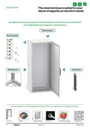
FDM121 display.<br />
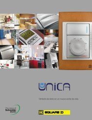
Connection with FDM121 display unit.<br />
PB103807-32<br />
Surface mount accessory.<br />
FDM121 switchboard display<br />
The FDM121 switchboard display unit can be connected to a Micrologic COM option<br />
(BCM ULP). It uses the sensors <strong>and</strong> processing capacity of the Micrologic control<br />
unit. It is easy to use <strong>and</strong> requires no special software or settings. It is immediately<br />
operational when connected to the COM option (BCM ULP) by a breaker ULP cord.<br />
The FDM121 is a large display, but requires very little depth. The anti-glare graphic<br />
screen is backlit for very easy reading even under poor ambient lighting <strong>and</strong> at sharp<br />
angles.<br />
Display of Micrologic measurements <strong>and</strong> trips<br />
The FDM121 is intended to display Micrologic A/E/P/H measurements, trips <strong>and</strong><br />
operating information. It cannot be used to modify the protection settings.<br />
Measurements may be easily accessed via a menu.<br />
Trips are automatically displayed.<br />
b A pop-up window displays the time-stamped description of the trip <strong>and</strong> the orange<br />
LED flashes<br />
Status indications<br />
When the circuit breaker is equipped with the COM option (BCM ULP) (including its<br />
set of sensors) the FDM121 display can also be used to view circuit breaker status<br />
conditions:<br />
b<br />
b<br />
b<br />
b<br />
O/F: ON/OFF<br />
SDE: Fault-trip indication (overload, short-circuit, ground fault).<br />
PF: ready to close<br />
CH: charged (spring loaded).<br />
Remote control<br />
When the circuit breaker is equipped with the COM option (BCM ULP) (including its<br />
kit for connection to XF <strong>and</strong> MX1 communication voltage releases), the FDM121<br />
display can also be used to control (open/close) the circuit breaker. Two operating<br />
mode are available.<br />
b local mode : open/close comm<strong>and</strong>s are enabled from FDM121 while disable from<br />
communication network<br />
b remote mode : open/close comm<strong>and</strong>s are disabled from FDM121 while, enabled<br />
from communication network.<br />
Main characteristics<br />
b 96 x 96 x 30 mm screen requiring 10 mm behind the door (or 20 mm when the<br />
24 volt power supply connector is used).<br />
b White backlighting.<br />
b Wide viewing angle: vertical ±60°, horizontal ±30°.<br />
b High resolution: excellent reading of graphic symbols.<br />
b Alarm LED: flashing orange for alarm pick-up, steady orange after operator reset if<br />
alarm condition persists.<br />
b Operating temperature range -10 °C to +55 °C.<br />
b CE / UL / CSA marking (pending).<br />
b 24 V DC power supply, with tolerances 24 V -20 % (19.2 V) to 24 V +10 % (26.4 V).<br />
When the FDM121 is connected to the communication network, the 24 V DC can be<br />
supplied by the communication system wiring system (see paragraph "Connection").<br />
b Consumption 40 mA.<br />
Mounting<br />
The FDM121 is easily installed in a switchboard.<br />
b St<strong>and</strong>ard door cut-out 92 x 92 mm.<br />
b Attached using clips.<br />
To avoid a cut-out in the door, an accessory is available for surface mounting by<br />
drilling only two 22 mm diameter holes.<br />
The FDM121 degree of protection is IP54 in front. IP54 is maintained after<br />
switchboard mounting by using the supplied gasket during installation.<br />
Connection<br />
The FDM121 is equipped with:<br />
b a 24 V DC terminal block:<br />
v plug-in type with 2 wire inputs per point for easy daisy-chaining<br />
v power supply range of 24 V DC -20 % (19.2 V) to 24 V DC +10 % (26.4 V).<br />
A 24 V DC type auxiliary power supply must be connected to a single point on the<br />
ULP system. The FDM121 display unit has a 2-point screw connector on the rear<br />
panel of the module for this purpose. The ULP module to which the auxiliary power<br />
supply is connected distributes the supply via the ULP cable to all the ULP modules<br />
connected to the system <strong>and</strong> therefore also to Micrologic.<br />
b two RJ45 jacks.<br />
The Micrologic connects to the internal communication terminal block on the<br />
<strong>Masterpact</strong> via the breaker ULP cord. Connection to one of the RJ45 connectors on<br />
the FDM121 automatically establishes communication between the Micrologic <strong>and</strong><br />
the FDM121 <strong>and</strong> supplies power to the Micrologic measurement functions.<br />
When the second connector is not used, it must be fitted with a line terminator.<br />
207E2200.indd<br />
version: 10.1<br />
A-25