Masterpact NT and NW
Masterpact NT and NW - Schneider Electric
Masterpact NT and NW - Schneider Electric
- No tags were found...

You also want an ePaper? Increase the reach of your titles
YUMPU automatically turns print PDFs into web optimized ePapers that Google loves.
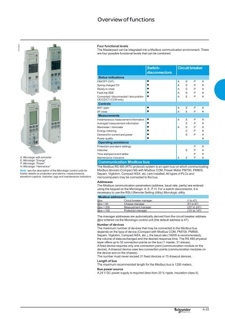
Overview of functions<br />
PB104804<br />
Four functional levels<br />
The <strong>Masterpact</strong> can be integrated into a Modbus communication environment. There<br />
are four possible functional levels that can be combined.<br />
A: Micrologic with ammeter<br />
E: Micrologic “Energy”<br />
P: Micrologic “Power”<br />
H: Micrologic “Harmonics”<br />
Note: see the description of the Micrologic control units for<br />
further details on protection <strong>and</strong> alarms, measurements,<br />
waveform capture, histories, logs <strong>and</strong> maintenance indicators.<br />
Switchdisconnectors<br />
Circuit breaker<br />
Status indications<br />
ON/OFF (O/F) b A E P H<br />
Spring charged CH b A E P H<br />
Ready to close b A E P H<br />
Fault-trip SDE b A E P H<br />
Connected / disconnected / test position b A E P H<br />
CE/CD/CT (CCM only)<br />
Controls<br />
MX1 open b A E P H<br />
XF close b A E P H<br />
Measurements<br />
Instantaneous measurement information b A E P H<br />
Averaged measurement information b E P H<br />
Maximeter / minimeter b A E P H<br />
Energy metering b E P H<br />
Dem<strong>and</strong> for current <strong>and</strong> power b E P H<br />
Power quality b H<br />
Operating assistance<br />
Protection <strong>and</strong> alarm settings P H<br />
Histories E P H<br />
Time stamped event tables P H<br />
Maintenance indicators A E P H<br />
Communication Modbus bus<br />
The Modbus RS 485 (RTU protocol) system is an open bus on which communicating<br />
Modbus devices (Compact NS with Modbus COM, Power Meter PM700, PM800,<br />
Sepam, Vigilohm, Compact NSX, etc.) are installed. All types of PLCs <strong>and</strong><br />
microcomputers may be connected to the bus.<br />
Addresses<br />
The Modbus communication parameters (address, baud rate, parity) are entered<br />
using the keypad on the Micrologic A, E, P, H. For a switch-disconnector, it is<br />
necessary to use the RSU (Remote Setting Utility) Micrologic utility.<br />
Modbus addresses<br />
@xx Circuit breaker manager (1 to 47)<br />
@xx + 50 Chassis manager (51 to 97)<br />
@xx + 200 Measurement manager (201 to 247)<br />
@xx + 100 Protection manager (101 to 147)<br />
The manager addresses are automatically derived from the circuit breaker address<br />
@xx entered via the Micrologic control unit (the default address is 47).<br />
Number of devices<br />
The maximum number of devices that may be connected to the Modbus bus<br />
depends on the type of device (Compact with Modbus COM, PM700, PM800,<br />
Sepam, Vigilohm, Compact NSX, etc.), the baud rate (19200 is recommended),<br />
the volume of data exchanged <strong>and</strong> the desired response time. The RS 485 physical<br />
layer offers up to 32 connection points on the bus (1 master, 31 slaves).<br />
A fixed device requires only one connection point (communication module on the<br />
device). A drawout device uses two connection points (communication modules on<br />
the device <strong>and</strong> on the chassis).<br />
The number must never exceed 31 fixed devices or 15 drawout devices.<br />
Length of bus<br />
The maximum recommended length for the Modbus bus is 1200 meters.<br />
Bus power source<br />
A 24 V DC power supply is required (less than 20 % ripple, insulation class II).<br />
207E2300.indd<br />
version: 10.1<br />
A-33