SPIDER® Rock protection system - Geobrugg AG
SPIDER® Rock protection system - Geobrugg AG
SPIDER® Rock protection system - Geobrugg AG

Create successful ePaper yourself
Turn your PDF publications into a flip-book with our unique Google optimized e-Paper software.
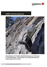
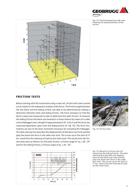
FRICTION TESTS<br />
Before starting with the actual tests using a rope net, friction tests were carried<br />
out as a basis for the subsequent analysis of the forces. The friction angle between<br />
the test block and the sliding surface was able to be determined by making a<br />
distinction between static and sliding friction. The force necessary to hold the<br />
block in place was measured in order to determine the static friction. To measure<br />
the sliding friction the block was lowered in a linear fashion by means of a cable<br />
crane (Habegger) over a length of approximately 0.20 - 0.25 m and the force was<br />
measured dependent upon time and displacement (cf. fi g. 19). The force fl uctuations<br />
are due to the lever movement necessary for actuating the Habegger.<br />
The dark staircase line describes the displacement of the block over time and the<br />
grey line shows the force in the cable over time. The curves up to the start at 17<br />
sec. result from the relieving of load via the chain hoist. The results from the fric-<br />
tion tests were as follows: for the static friction, a friction angle of ϕ = 28 – 29°<br />
H<br />
and for the sliding friction, a friction angle of ϕ = 24 – 25°.<br />
G<br />
Fig. 13: Central perspective side view<br />
showing the spatial position of the<br />
anchor<br />
Fig. 14: Friction tests<br />
Fig. 15: Result of a friction test for<br />
measuring the sliding friction. The dark<br />
staircase line describes the displacement<br />
of the block over time and the<br />
grey line shows the force in the cable<br />
over time. The curves up to the start at<br />
17 sec. result from the relieving of load<br />
via the chain hoist.<br />
7