The ERFA system prevents a collapse and protects ... - Geobrugg AG
The ERFA system prevents a collapse and protects ... - Geobrugg AG
The ERFA system prevents a collapse and protects ... - Geobrugg AG

You also want an ePaper? Increase the reach of your titles
YUMPU automatically turns print PDFs into web optimized ePapers that Google loves.
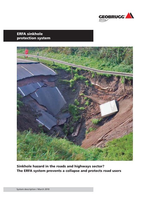
<strong>ERFA</strong> sinkhole<br />
protection <strong>system</strong><br />
Sinkhole hazard in the roads <strong>and</strong> highways sector?<br />
<strong>The</strong> <strong>ERFA</strong> <strong>system</strong> <strong>prevents</strong> a <strong>collapse</strong> <strong>and</strong> <strong>protects</strong> road users<br />
System description / March 2010
<strong>ERFA</strong> sinkhole protection <strong>system</strong> / System description / March 2010<br />
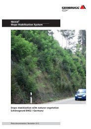
Sinkhole hazard in the roads <strong>and</strong> highways<br />
sector? <strong>The</strong> <strong>ERFA</strong> <strong>system</strong> <strong>prevents</strong> a <strong>collapse</strong><br />
<strong>and</strong> <strong>protects</strong> road usersd<br />
Photo on front page: State offi ce for<br />
geology <strong>and</strong> mining of Saxony-Anhalt /<br />
Germany<br />
2<br />
INTRODUCTION<br />
Sinkholes <strong>and</strong> depressions occur in connection with the leaching of soluble<br />
rock such as limestone, gypsum or salt or are the consequences of the <strong>collapse</strong><br />
of artifi cially created subterranean cavities for instance by the underground<br />
mining of brown coal or lignite. <strong>The</strong>y occur sporadically <strong>and</strong> are to date, diffi<br />
cult or impossible to predict.<br />
As existing road <strong>and</strong> highway networks must be constantly adapted <strong>and</strong> extended<br />
due to demographic development it is often unavoidable to cross<br />
areas with a high risk of sinkholes. Depending on specifi c project requirements<br />
<strong>and</strong> boundary conditions a highway routes run on dams, on more or less fl at<br />
terrain or in cuttings.<br />
With respect to actions for sinkhole prevention, a distinction is made between<br />
those providing full <strong>and</strong> partial protection.<br />
Protection methods already established on the market require either a correspondingly<br />
thick covering with spoil or rubble or the insertion of a massively<br />
reinforced concrete slab. Where a road is to be created on a proposed<br />
dam, the principal economic method is certainly the use of high tensile<br />
strength geoplastics. In this case there is a requirement for an adequate covering<br />
in order to activate the arching effect.<br />
Where – with the aim of full protection – very high requirements are to be<br />
satisfi ed with respect to maximum permissible deformations, for example for<br />
German Federal Railways high-speed train routes, then often only rigid protection<br />
measures are applicable, such as the installation of massively reinforced<br />
concrete slabs. Structure changing measures such as the use of explosives,<br />
dynamic intensive compression or the removal <strong>and</strong> replacement of the<br />
subsoil are outside the scope of this documentation.<br />
Numerous projects are now in existence which - for reasons of economy - favor<br />
the smallest possible covering with rubble for bridging areas with a risk<br />
of sinkholes (in cuttings for instance). Also the concept of partial protection<br />
is often preferred instead of cost-intensive full protection.<br />
<strong>The</strong> aim of <strong>Geobrugg</strong> <strong>AG</strong>, based upon its many years’ experience with protection<br />
measures in the sphere of natural hazards, such as rockfall, avalanches,<br />
earth slips or shallow l<strong>and</strong>slides is to offer an economic <strong>system</strong> for protecting<br />
roads <strong>and</strong> highways endangered by sinkholes. In the fi rst place, the required<br />
covering with spoil or rubble should be kept to a bare minimum, <strong>and</strong> secondly<br />
the rigidity of the <strong>system</strong> should be selected so as to be able to minimize<br />
the anticipated deformations as far as possible.
This technical documentation describes the newly developed <strong>system</strong> with its<br />
components, summarizes the results of the performed full-scale fi eld tests<br />
<strong>and</strong> informs on the installation <strong>and</strong> dimensioning.<br />
OBJECTIVES<br />
<strong>The</strong> <strong>ERFA</strong> <strong>system</strong> pursues the notion of partial protection with the aim of reducing<br />
the risk of sinkholes <strong>and</strong> the associated costs to an acceptable level<br />
through cost-effective <strong>and</strong> simple action. Here, in the case of an event the<br />
<strong>system</strong> may deform to the extent that a sinkhole is visually perceptible while<br />
protecting the safety of road users. Compared to a rigid structure, it can then<br />
react promptly to prevent a progressive breaking away of the subsoil.<br />
Installation should be able to take place simply <strong>and</strong> quickly <strong>and</strong> the required<br />
insertion depth kept to a minimum.<br />
Great emphasis is placed on the high degree of strength of the <strong>system</strong> elements,<br />
thereby enabling insertion damage to be prevented or kept to a bare minimum.<br />
<strong>The</strong> <strong>system</strong> is to be conceived <strong>and</strong> structured on a modular basis to permit<br />
simple adaptation to different project requirements <strong>and</strong> changing boundary<br />
conditions.<br />
It must be determined whether existing dimensioning concepts are compatible<br />
with the effective load bearing behavior of the new protection <strong>system</strong>. Where<br />
necessary an adequate dimensioning concept is to be elaborated.<br />
Special attention should be paid to corrosion protection <strong>and</strong> thus adapted to<br />
project-specifi c requirements.<br />
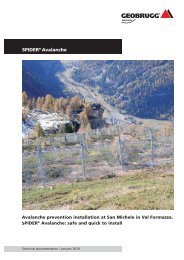
Fig. 1: Examples of sinkholes: Pizza Hut<br />
in Bearver County, Pennsylvania, USA<br />
(above) <strong>and</strong> Munich, Germany (left)<br />
3
<strong>ERFA</strong> sinkhole protection <strong>system</strong> / System description / March 2010<br />
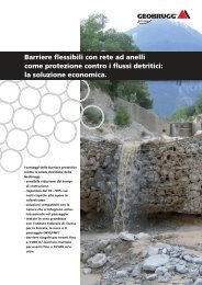
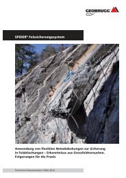
Fig.2: Photos from the full-scale fi eld<br />
test in Goldach SG, Switzerl<strong>and</strong><br />
4<br />
<strong>ERFA</strong> SINKHOLE PROTECTION SYSTEM<br />
<strong>The</strong> <strong>ERFA</strong> sinkhole protection <strong>system</strong> is characterized by linear, rigid bearing<br />
elements combined with a high-strength diamond-shaped steel mesh acting<br />
as a fl at force spreading element.<br />
Serving for load transfer in the road longitudinal axis are st<strong>and</strong>ard reinforce-<br />
ment steel str<strong>and</strong>s of high-tensile steel wire. As a result of the high deformation<br />
rigidity, the linear load bearing elements can transfer considerable forces with<br />
very slight defl ection. A force transfer of 2 000 – 2 500 kN/m is possible without<br />
problems.<br />
<strong>The</strong> <strong>system</strong> rigidity plus the load bearing capacity is directly infl uenced by the<br />
choice of the number of str<strong>and</strong>s per running meter <strong>and</strong> their cross-sectional<br />
area. By this means, the <strong>system</strong> can be optimally adapted to the project-specifi<br />
c requirements <strong>and</strong> boundary conditions.<br />
<strong>The</strong> linear load bearing elements are held together by means of the hightensile<br />
steel wire mesh which is placed over them, exerting a spreading effect.<br />
This <strong>prevents</strong> the breakage of individual str<strong>and</strong>s through the pavement.<br />
Due to optimal interaction with the rubble the anchoring section of the combi<br />
product can be considerably reduced longitudinally.<br />
Through the choice of diameter of the reinforcement steel str<strong>and</strong>s <strong>and</strong> their<br />
mutual spacing, the load bearing capacity <strong>and</strong> the maximum defl ection in the<br />
case of an event is adaptable to the project-specifi c requirements.
Linear load bearing elements<br />
According to the supplier data the linear main load bearing elements used in<br />
the st<strong>and</strong>ard <strong>ERFA</strong> sinkhole protection <strong>system</strong> possess the following characteristics:<br />
Parameter Value<br />
Nominal diameter in inches D = 0.6’’<br />
Nominal diameter in mm D = 15.7 mm<br />
Nominal cross-section A = 150 mm P 2<br />
Weight G = 1180 g/m<br />
Yield stress f = 1590 N/ mm y 2<br />
Minimum tensile strength f = 1770 N/ mm tk 2<br />
Fracture force P = 266 kN<br />
tk<br />
Number of wires 6 + 1<br />
Diameter of the outer wires 5.20 mm<br />
Diameter of the inner wire 5.35 mm<br />
Elongation at maximum load 3.5 %<br />
Contraction Ψ = 30 %<br />
E-modulus (mean value) E = 195’000 N/ mm P 2<br />
Relaxation over 1 000 h, 20°C, 0.70 ftk max. 2.5 %<br />
<strong>The</strong> following illustration shows a schematic tension-elongation diagram for<br />
a reinforcement steel str<strong>and</strong> according to the specifi cation in Table 1.<br />
Flat load bearing element<br />
<strong>The</strong> high-tensile steel wire mesh used with the <strong>ERFA</strong> <strong>system</strong> as a force spreading<br />
load bearing element, for instance TECCO ® G65/4, was specially developed<br />
by <strong>Geobrugg</strong> <strong>AG</strong> for applications with high dem<strong>and</strong>s. It possesses the following<br />
characteristics:<br />
Tab. 1: Characteristics of a reinforcement<br />
steel str<strong>and</strong> as a linear main load<br />
bearing element<br />
Fig. 3: Tension-elongation diagram for a<br />
reinforcement steel str<strong>and</strong> with<br />
nominal cross-section A p = 150 mm 2<br />
5
<strong>ERFA</strong> sinkhole protection <strong>system</strong> / System description / March 2010<br />
Tab. 2.: Characteristics of the TECCO ®<br />
G65/4 steel wire mesh<br />
Fig. 4: High-tensile TECCO ® G65/4 steel<br />
wire mesh with a tensile strength of<br />
250 kN/m<br />
Fig. 5: Tensile test of a high-tensile<br />
TECCO ® G65/4 steel wire mesh, net size:<br />
13 x 7 meshes, width of the tested mesh<br />
sample: 1.08 m, fracture load: 280.8 kN,<br />
test carried out on 25.01.2008<br />
6<br />
Parameter Value<br />
Diagonal x · y = 83 · 138 mm (+/- 3%)<br />
Mesh width D I = 63 mm (+/- 3%)<br />
Number of longitudinal meshes per m n l = 7.2 Stk/m<br />
Number of transverse meshes per m n q = 12.0 Stk/m<br />
Material high-tensile steel wire<br />
Minimum tensile strength f tk = 1770 N/ mm 2<br />
Wire diameter d = 4.0 mm<br />
Tensile strength of a single wire Z w = 22 kN<br />
Mesh tensile strength z l = 250 kN/m<br />
Weight g = 3.3 kg/m 2
Connectors<br />
In the full-scale fi eld tests in Goldach SG, Switzerl<strong>and</strong> the str<strong>and</strong>s were nonpositively<br />
connected using wire rope clips, topped by the TECCO ® G65/4 steel<br />
wire mesh. This type of connection was expedient for test purposes. For projectrelated<br />
applications however, the wire rope clips are to be replaced by other<br />
elements permitting more rational mounting.<br />
One possibility in place of wire rope clips is the use of aluminum press sleeves,<br />
which can be mounted at the factory. Here it is recommended to join the mesh<br />
over the knots with the str<strong>and</strong>s.<br />
A further possibility is the use of intermeshing metal rails, which surround the<br />
str<strong>and</strong>s <strong>and</strong> the mesh <strong>and</strong> are non-positively connected together.<br />
It is recommended to non-positively connect the str<strong>and</strong>s with the mesh at intervals<br />
of approx. 2.5 – 3.0 m.<br />
<strong>ERFA</strong> <strong>system</strong>s<br />
<strong>The</strong> tensile strength of the <strong>ERFA</strong> <strong>system</strong> can be optimally adapted to the project-<br />
specifi c requirements by the choice of main load bearing elements <strong>and</strong> their<br />
number per running meter. Three st<strong>and</strong>ard <strong>ERFA</strong> <strong>system</strong>s are available.<br />
<strong>ERFA</strong> LIGHT:<br />
Parameter Value<br />
Nominal diameter of linear load bearing element D = 15.7 mm<br />
Nominal cross-section A = 150 mm P 2<br />
Fracture strength per linear load bearing element P = 266 kN<br />
tk<br />
Number of linear load bearing elements per m n = 4 Stk/m<br />
Total fracture force per m R = 1060 kN/m<br />
tk<br />
Total cross-sectional area per m A = 600 mm tot 2 /m<br />
Fig. 6: Connecting the mesh with the<br />
str<strong>and</strong>s in the full-scale fi eld tests in<br />
Goldach SG, Switzerl<strong>and</strong><br />
Tab. 3: Characteristics of the <strong>ERFA</strong> Light<br />
<strong>system</strong><br />
Fig.7: Schematic representation of the<br />
<strong>ERFA</strong> Light <strong>system</strong><br />
7
<strong>ERFA</strong> sinkhole protection <strong>system</strong> / System description / March 2010<br />
Tab. 4: Characteristics of the <strong>ERFA</strong> Med<br />
<strong>system</strong><br />
Fig. 8: Schematic representation <strong>ERFA</strong><br />
Med <strong>system</strong><br />
Tab. 5: Characteristics of the <strong>ERFA</strong> Pro<br />
<strong>system</strong><br />
Fig. 9: Schematic representation <strong>ERFA</strong><br />
Pro <strong>system</strong><br />
8<br />
<strong>ERFA</strong> MED:<br />
Parameter Value<br />
Nominal diameter of linear load bearing element D = 15.7 mm<br />
Nominal cross-section Ap = 150 mm2 Fracture strength per linear load bearing element P = 266 kN<br />
tk<br />
Number of linear load bearing elements per m n = 6 Stk/m<br />
Total fracture force per m R = 1590 kN/m<br />
tk<br />
Total cross-sectional area per m A = 900 mm tot 2 /m<br />
<strong>ERFA</strong> PRO:<br />
Parameter Value<br />
Nominal diameter of linear load bearing element D = 15.7 mm<br />
Nominal cross-section Ap = 150 mm2 Fracture strength per linear load bearing element P = 266 kN<br />
tk<br />
Number of linear load bearing elements per m n = 8 Stk/m<br />
Total fracture force per m R = 2120 kN/m<br />
tk<br />
Total cross-sectional area per m A = 1200 mm tot 2 /m
APPLICATION<br />
<strong>The</strong> <strong>ERFA</strong> sinkhole protection <strong>system</strong> is usable for the protection of highways<br />
<strong>and</strong> roads with asphalt <strong>and</strong> concrete coverings. To permit subsequent restoration<br />
<strong>and</strong> problem-free surface removal, it is recommended that the reinforcement<br />
is placed in the frost protection layer <strong>and</strong> not in the asphalt load<br />
bearing layer.<br />
In reference to the guidelines for road surface superstructure st<strong>and</strong>ardization<br />
RStO 01 (edition 2001), this means in construction class II for instance, with<br />
a dimension-relevant traffi c load B of 3 – 10 mill. equivalent 10-t axle transits,<br />
that the reinforcement is installed in the 54 cm thick frost protection layer<br />
with an 80 cm frost-proof superstructure.<br />
FULL-SCALE FIELD TESTS<br />
To verify the functional suitability of the <strong>ERFA</strong> <strong>system</strong>, full-scale 1:1 fi eld tests<br />
were carried out in Goldach SG, Switzerl<strong>and</strong> in October 2008 <strong>and</strong> February<br />
2009. Installed fi rst was an asphalt load bearing layer <strong>and</strong> secondly a concrete<br />
slab with thicknesses of 20 cm <strong>and</strong> widths of 2.5 m. <strong>The</strong> concrete slab was<br />
not reinforced. <strong>The</strong> modeled sinkhole exhibited a rectangular hollow with a<br />
free span width of 3.0 m. A total of 17 reinforcement steel str<strong>and</strong>s with the<br />
characteristics detailed in Tab. 1 were installed.<br />
After the form removal, both constructions were loaded with weights. <strong>The</strong><br />
deformations of the slab were then measured with reference to the loading.<br />
A total loading of 30.4 tons resulted in a depression in the slab center with<br />
a length of approx. 20 cm. This load corresponds to traffi c regulation loading<br />
for heavy goods trucks with a total load of 600 kN in accordance with DIN<br />
1072. <strong>The</strong> loading was not able to be increased due to the unavailability of<br />
further weights. <strong>The</strong> <strong>ERFA</strong> <strong>system</strong> showed considerable reserves to be available.<br />
Fig. 10: Placing the <strong>ERFA</strong> <strong>system</strong> <strong>and</strong><br />
placing the concrete slabs<br />
Fig. 11: Full-scale fi eld test in Goldach<br />
SG, Switzerl<strong>and</strong>, in October 2008<br />
(concrete) <strong>and</strong> in February 2009<br />
(asphalt)<br />
9
<strong>ERFA</strong> sinkhole protection <strong>system</strong> / System description / March 2010<br />
Fig. 12: Break-in model from EBGEO<br />
02/2009<br />
10<br />
DIMENSIONING<br />
In the latest draft of the EBGEO (Recommendations on Soil Reinforcement<br />
with Geosynthetics), edition 02/2009, a distinction is made between the break-<br />
in model <strong>and</strong> the arch model.<br />
According to Figures 1a <strong>and</strong> 1b, break-in models are more likely to develop<br />
where non-cohesive rubble material exhibits a relatively low layering density,<br />
or where the diameter of the sinkhole is relatively large compared to<br />
the thickness of the rubble layer.<br />
Where the non-cohesive rubble material exhibits a high layering density <strong>and</strong><br />
good serration, then with adequate thickness in the bridging zone, an arch<br />
or coupling structure will develop (Figs. 2a <strong>and</strong> 2b). <strong>The</strong> broken up material<br />
below the pressure zone increasingly loads the reinforcement with its own<br />
weight <strong>and</strong> any applied load. Over the course of time the arch can <strong>collapse</strong>,<br />
in particular with dynamic effects, so that then the reinforcement is fully<br />
loaded by the applied load weight (as in Fig. 1a).
When using the <strong>ERFA</strong> <strong>system</strong>, the thickness of the spoil plus the combined<br />
binder <strong>and</strong> top layers is relatively small compared with the sinkhole diameter<br />
(H/D < 1). As a result no load bearing arch can form. Corresponding to the<br />
break-in model, the total applied load is to be carried through the membrane.<br />
<strong>The</strong> resulting forces are to be transferred laterally in the road longitudinal axis.<br />
<strong>The</strong> <strong>ERFA</strong> <strong>system</strong> possesses pronounced anisotropic characteristics <strong>and</strong> hence<br />
can be dimensioned for the level case according to the membrane theory. As<br />
a simplifi cation, the membrane can be regarded as a single rope. This represents<br />
an easily bent load bearing element which can absorb tensile forces only.<br />
In order to estimate the anticipated deformations as a function of the rigidities<br />
of the load bearing elements <strong>and</strong> the adjacent subsoil, fi nite element analyses<br />
can be performed as a supplement to this or for plausibility checking.<br />
CORROSION PROTECTION<br />
Because the elements of the <strong>ERFA</strong> <strong>system</strong> are steel products, appropriate attention<br />
must be paid to corrosion protection. <strong>Geobrugg</strong>’s many years’ experience<br />
in the fi eld of protection measures against natural hazards is a bonus<br />
here.<br />
<strong>The</strong> aggressiveness of the environment decisively infl uences the corrosion process.<br />
<strong>The</strong> rate of wear is generally assumed to be low in rural districts, providing<br />
that road salt is not used locally. In comparison, a signifi cantly greater<br />
corrosion effect is to be anticipated in an industrial or coastal zone.<br />
This is also confi rmed by the results of investigations carried out by Prof. Nünninghoff<br />
on zinc-aluminum coated wire samples which were exposed to corrosion<br />
for up to 21 years. <strong>The</strong> anticipated wear over a period of 100 years is<br />
approx. 32 μm in industrial zones in comparison with only approx. 16 μm in<br />
rural districts. Moreover the rate of corrosion is essentially dependent on the<br />
microclimate in the immediate surrounds of the steel wire products.<br />
<strong>The</strong> usual Zn/Al coating of the linear <strong>and</strong> fl at load bearing elements is 150 g/m 2 ,<br />
corresponding to a coating of 21 μm. According to project requirements, the<br />
Fig. 13: Rope under a given load q(x)<br />
11
<strong>ERFA</strong> sinkhole protection <strong>system</strong> / System description / March 2010<br />
Fig. 14: Results of salt spray tests carried<br />
out by Prof. Nünninghoff; interpolation<br />
through <strong>Geobrugg</strong> <strong>AG</strong><br />
12<br />
cladding can be increased to 200 g/m 2 (= 28 μm) or 250 g/m 2 (= 35 μm). Stainless<br />
steels can be used where very high dem<strong>and</strong>s are placed on the corrosion protection.<br />
If a pure Zn coating is used, a 3 – 4 times shorter service life is to be<br />
expected in comparison to a Zn/Al coating of the same cladding quantity. This<br />
is shown in the following diagram from Prof. Nünninghoff’s study, which represents<br />
the results of salt spray tests on wires with a Zn, respectively a Zn/Al<br />
cladding of 300 g/m2 . <strong>The</strong> red <strong>and</strong> blue curves were interpolated through<br />
<strong>Geobrugg</strong> <strong>AG</strong>. <strong>The</strong> 95% Zn / 5% aluminum cladding is known under the trade<br />
name of GEOBRUGG SUPERCOATING ® , GALFAN ® or BEZINAL ® .<br />
MAKING-UP<br />
<strong>The</strong> <strong>ERFA</strong> <strong>system</strong> is delivered coiled on reels. <strong>The</strong> linear load bearing elements<br />
are non-positively attached to the fl at load bearing element. <strong>The</strong> st<strong>and</strong>ard width<br />
is 2.0 m. On request the panel width can be adapted specifi cally to a project. <strong>The</strong><br />
maximum possible panel width is 3.5 m. <strong>The</strong> st<strong>and</strong>ard roll length is 100 m. On<br />
request the length of a roll can be specially adapted to the project.<br />
PLACING<br />
General<br />
<strong>The</strong> <strong>ERFA</strong> <strong>system</strong> is placed using a reel unwinding device. Care is to be taken that<br />
the <strong>system</strong> is placed as tautly as possible. Normally the <strong>system</strong> is not actively<br />
tensioned. <strong>The</strong> <strong>ERFA</strong> <strong>system</strong> is to be placed to produce the best possible bonding<br />
with the rubble material. Cavities in the region of the load bearing elements are<br />
to be avoided. <strong>The</strong> required deformation moduli are to be guaranteed.
<strong>The</strong> maximum grain size of the preferably broken rubble for the frost protection<br />
layer should be adapted to the opening width of the high-tensile mesh. If the<br />
maximum grain size is signifi cantly smaller than the width of the mesh openings,<br />
steps are to be taken to prevent rubble material falling though on the occurrence<br />
of a sinkhole, for instance by placing a non-woven or fl eece covering.<br />
Longitudinal butt joints<br />
Two basic possibilities exist for the longitudinal butt jointing of the <strong>ERFA</strong><br />
<strong>system</strong>:<br />
1. Overlapping with point connections<br />
2. Use of str<strong>and</strong> couplings<br />
If the <strong>ERFA</strong> <strong>system</strong> is joined by overlapping, the end of the fi rst roll with the<br />
projecting mesh is to be placed over the projecting exposed str<strong>and</strong>s of the<br />
second roll. <strong>The</strong> str<strong>and</strong>s must mutually overlap suffi ciently so that depending<br />
on the type of connection, the fully load bearing capacity can be transferred<br />
from the one str<strong>and</strong> of the fi rst roll to the other str<strong>and</strong> of the second roll.<br />
Fig. 15: End of the fi rst roll with<br />
projecting mesh<br />
Fig. 16: Beginning of the second roll with<br />
projecting str<strong>and</strong>s<br />
13
<strong>ERFA</strong> sinkhole protection <strong>system</strong> / System description / March 2010<br />
Abb. 17: Str<strong>and</strong> couplings<br />
Depth of the foundation under terrain<br />
Fig. 18: End anchorage possibility<br />
14<br />
Foundation height<br />
Depth of the anchorage<br />
Foundation width<br />
Foundation of the anchorage<br />
of the <strong>ERFA</strong> <strong>system</strong><br />
A second possible variant is the use of str<strong>and</strong> couplings according to the manufacturer’s<br />
data. Normally these consist of a coupling head, a coupling sleeve, a<br />
wedge set <strong>and</strong> a spring.<br />
Transverse butt joints<br />
Due to the pronounced anisotropic characteristics, the lateral interconnection<br />
of the panels is not critical. <strong>The</strong> edge meshes of the high-tensile steel wire mesh<br />
can, for instance, be interconnected by appropriate clips or shackles.<br />
End anchorage<br />
<strong>The</strong> execution of the end anchorage is basically dependent on the project-specifi<br />
c boundary conditions. <strong>The</strong> fi gure below shows one possibility as to how at<br />
least part of the load bearing capacity of the protection <strong>system</strong> can be anchored<br />
via an end beam.<br />
Length of the anchorage zone<br />
Asphalt wearing course<br />
Asphalt binder course<br />
Asphalt base course<br />
<strong>ERFA</strong>-System<br />
Frost protection layer<br />
<strong>The</strong> position <strong>and</strong> dimensions of the foundation are to be adapted to the project<br />
<strong>and</strong> its boundary conditions. Where necessary this should be additionally backanchored<br />
via anchors <strong>and</strong> extruded posts.<br />
<strong>The</strong> withdrawal strength of the protection <strong>system</strong> in the frost protection layer,<br />
which is directly dependent on the applied load may be taken into account in<br />
the area outside the zone directly infl uenced by the mobilization of the passive<br />
earth resistance. <strong>The</strong> anchorage of the <strong>ERFA</strong> <strong>system</strong> is to be located suffi ciently<br />
far outside the area endangered by the sinkhole.
Reinforcing of the boundary zone<br />
In the event that the boundary zone requires reinforcement, an additional<br />
str<strong>and</strong> or a spiral rope of comparable rigidity can be installed at the factory or<br />
on-site <strong>and</strong> fi xed non-positively.<br />
Bends, roundabout traffi c, recesses<br />
By placing additional linear load bearing elements such as reinforcement steel<br />
str<strong>and</strong>s or spiral ropes of comparable rigidity, the load bearing behavior <strong>and</strong><br />
capacity can be adapted to special boundary conditions such as in bends, with<br />
roundabout traffi c <strong>and</strong> in the area of recesses.<br />
CLOSING REMARKS<br />
<strong>The</strong> <strong>ERFA</strong> protection <strong>system</strong> is adaptable economically <strong>and</strong> according to proj-<br />
ect-specifi c requirements. It has proved its functional suitability in 1:1 full-scale<br />
fi eld tests.<br />
Due to the high load bearing capacity of the reinforcement steel str<strong>and</strong>s<br />
combined with rigid load bearing behavior, there are only slight deformations<br />
with considerable span widths <strong>and</strong> infl uences.<br />
Compared with geoplastic solutions, creep deformations are negligible. Steel<br />
products also provide a high load bearing capacity to being driven over during<br />
installation or under transverse stresses.<br />
<strong>The</strong> <strong>ERFA</strong> sinkhole protection <strong>system</strong> is installed in the loose stone layer below<br />
the fi rst bituminously or hydraulically bonded layer or the concrete supporting<br />
layer. Expenditure on earthwork in particular with restorations or in cuttings<br />
is kept to a minimum. <strong>The</strong> dimensioning concept is adapted accordingly.<br />
<strong>The</strong> <strong>ERFA</strong> protection <strong>system</strong> could also be installed directly in the concrete<br />
slab. This essentially changes the load bearing behavior. Also in this case,<br />
subsequent restoration work will be very costly. Due to the reinforcement,<br />
simple surface removal is no longer possible.<br />
Direct reinforcing of the asphalt slab is not recommended. High loading can<br />
result in the detachment of parts of the asphalt layers which become arched,<br />
endangering road users.<br />
15
<strong>Geobrugg</strong> <strong>protects</strong> people <strong>and</strong> infrastructures from the<br />
forces of nature<br />
It is the task of our engineers <strong>and</strong> partners to analyze the problem<br />
together with you in detail <strong>and</strong> then, together with local consultants,<br />
to present solutions. Painstaking planning is not the only thing<br />
you can expect from us, however; since we have our own production<br />
plants on three continents, we can offer not only short delivery paths<br />
<strong>and</strong> times, but also optimal local customer service. With a view towards<br />
a trouble-free execution, we deliver preassembled <strong>and</strong> clearly<br />
identifi ed <strong>system</strong> components right to the construction site. <strong>The</strong>re<br />
we provide support, if desired, including technical support – from<br />
installation right on up until acceptance of the structure.<br />
Rockfall barriers<br />
Rockfall drapes<br />
Slope stabilization <strong>system</strong>s<br />
Debris fl ow barriers<br />
Avalanche prevention structures<br />
Open pit rockfall barriers<br />
Special applications<br />
<strong>Geobrugg</strong> <strong>AG</strong><br />
Geohazard Solutions<br />
Aachstrasse 11 • CH-8590 Romanshorn<br />
Phone +41 71 466 81 55 • Fax +41 71 466 81 50<br />
www.geobrugg.com • info@geobrugg.com<br />
A company of the BRUGG Group ISO 9001 certifi ed<br />
1.402.24.EN.1003