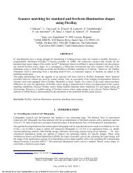
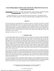
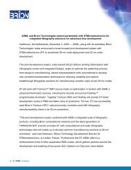
28 27 26 Image border reflection effect. 27 nm dense lines exposed on NXE:3100 CD, nm 25 24 H lines meas 23 H-lines Tachyon sim V-lines meas 22 V-lines Tachyon sim 21 0 0.2 0.4 0.6 0.8 1 distance to neighboring field, mm Figure 14 Wafer layout <strong>of</strong> the die-spacing experiment (left) <strong>and</strong> the results <strong>of</strong> the experiment <strong>and</strong> Tachyon simul<strong>at</strong>ion (right). CD drop <strong>of</strong> about 4 nm is observed for small distances between fields. Several biases <strong>of</strong> 27 nm horizontal dense lines were measured. The results <strong>of</strong> the experiment are shown in Figure 14 (right). CD drop <strong>of</strong> 3.9 nm was observed for vertical lines <strong>and</strong> <strong>of</strong> 4.6 ± 0.4 nm for different horizontal lines biases. Therefore vertical lines are less sensitive to the effect, also horizontal lines with larger neg<strong>at</strong>ive bias show smaller sensitivity (Figure 15). Notice th<strong>at</strong> nominal design CD is shown, actual mask CD may differ. CD drop, nm 5.2 5 4.8 4.6 4.4 Loc<strong>at</strong>ion 1 Loc<strong>at</strong>ion 2 4.32 CD drop as function <strong>of</strong> bias 4.59 5.05 4.93 4.2 4.14 4 23.5 24 24.5 25 25.5 26 26.5 Nominal CD, nm Figure 15 CD drop due to field to field reflections as function <strong>of</strong> mask bias measured <strong>at</strong> two different loc<strong>at</strong>ions in the field. Lines with larger neg<strong>at</strong>ive bias are less sensitive to the effect. It follows from the experiment th<strong>at</strong> a safe distance <strong>of</strong> sensitive structure from the edge <strong>of</strong> the neighboring field should be about 400 um. The transition region determined by a half-shadow <strong>of</strong> Reticle <strong>Mask</strong>ing Blades is about 200 um. To prevent a CDU impact from field-to-field flare, the mask black border should have very low EUV reflectivity (< 0.2%), which can only be achieved by absorber stack optimiz<strong>at</strong>ion (for example, using a very thick absorber), a special co<strong>at</strong>ing, double absorber technique or etching away the entire ML in the black border area [10],[11] . However, the CD impact can also be minimized by means <strong>of</strong> OPC, using inform<strong>at</strong>ion about exposure tool geometry <strong>and</strong> layout <strong>and</strong> also knowledge <strong>of</strong> absorber stack reflectivity. Such a s<strong>of</strong>tware solution is implemented in Brion Tachyon OPC. The image border effect measured on NXE:3100 is simul<strong>at</strong>ed by the Tachyon EUV model, as shown in Figure 14 (right). The transition region <strong>and</strong> the CD drop were reproduced in simul<strong>at</strong>ion. This shows potential possibility <strong>of</strong> mask OPC correction for the image border reflection effect. The image border effect accumul<strong>at</strong>es in the corners <strong>of</strong> the image field because reflections from three neighboring fields are summed up there. It was shown in an NXE:3100 experiment th<strong>at</strong> the cumul<strong>at</strong>ive CD drop in the corners is larger than 7.5 nm for 70 nm absorber mask <strong>and</strong> 30 nm dense lines [12] . Proc. <strong>of</strong> SPIE Vol. 8166 816624-10 Downloaded From: http://proceedings.spiedigitallibrary.org/ on 04/08/2013 Terms <strong>of</strong> Use: http://spiedl.org/terms
6. SUMMARY AND DISCUSSION Several <strong>aspects</strong> <strong>of</strong> mask contribution to <strong>imaging</strong> were considered. In particular, the impact <strong>of</strong> mask centroid wavelength on apodiz<strong>at</strong>ion, telecentricity <strong>and</strong> CD uniformity was shown. The optimal centroid wavelength <strong>of</strong> ML blank was determined based on detailed scanner spectrum aware simul<strong>at</strong>ion simul<strong>at</strong>ions with a rigorous 3d mask model calibr<strong>at</strong>ed on measured d<strong>at</strong>a. This centroid wavelength was found to be 13.52±0.01 nm based on ML reflectivity uniformity metrics <strong>and</strong> 13.54±0.01 nm based on apodiz<strong>at</strong>ion minimiz<strong>at</strong>ion. This confirms earlier ASML recommend<strong>at</strong>ion 13.53 nm for centroid wavelength. Preliminary CD uniformity simul<strong>at</strong>ions are performed indic<strong>at</strong>ing th<strong>at</strong> CDU impact <strong>of</strong> ML thickness vari<strong>at</strong>ion can be essentially reduced if the centroid wavelength is optimized. However p<strong>at</strong>tern placement simul<strong>at</strong>ions show th<strong>at</strong> telecentricity might go out <strong>of</strong> specific<strong>at</strong>ion for future <strong>node</strong>s. More detailed spectral simul<strong>at</strong>ions will follow. We have continued the investig<strong>at</strong>ion [3] <strong>of</strong> absorber height <strong>and</strong> bias impact on <strong>imaging</strong> by means <strong>of</strong> simul<strong>at</strong>ions with the calibr<strong>at</strong>ed mask model <strong>and</strong> by means <strong>of</strong> NXE:3100 exposures. In particular, the simul<strong>at</strong>ions show th<strong>at</strong> larger absorber heights give advantage in exposure l<strong>at</strong>itude for larger angular illumin<strong>at</strong>ion (higher NAσ) for 27 nm <strong>node</strong>. In other words, increase in absorber volume provides better optical contrast in case <strong>of</strong> <strong>of</strong>f axis illumin<strong>at</strong>ion. This effect was confirmed with NXE:3100 experiment showing higher exposure l<strong>at</strong>itude for 70 nm absorber mask compared to 55.4 nm mask for 27 nm dense, semi-dense <strong>and</strong> isol<strong>at</strong>ed lines. This study shows th<strong>at</strong> there is no immedi<strong>at</strong>e need to go to smaller absorber height for future <strong>node</strong>s if proper shadowing bias is applied on the mask. Also the study [3],[9] on image border reflections was continued. It was shown by NXE:3100 experiments th<strong>at</strong> image border reflections can cause CD drop <strong>of</strong> about 4 nm <strong>of</strong> 27 nm dense lines <strong>at</strong> the edge <strong>of</strong> the field for 55 nm absorber mask with 1.4% reflectance. This effect was reproduced by Brion Tachyon simul<strong>at</strong>ions showing a correction potential by means <strong>of</strong> mask OPC. 7. ACKNOWLEDGEMENTS The authors would like to thank Johannes Ru<strong>of</strong>f <strong>and</strong> Peter Huber from Carl Zeiss Oberkochen for providing optical system d<strong>at</strong>a for simul<strong>at</strong>ions. We thank Gian Lorusso <strong>and</strong> Eric Hendrickx from IMEC <strong>and</strong> Franklin Kalk <strong>and</strong> Hiroaki Morimoto from Toppan for fruitful cooper<strong>at</strong>ion <strong>and</strong> discussions. We thank Yasuko Saito from Brion for image border effect simul<strong>at</strong>ion support. We thank many colleagues <strong>at</strong> ASML for providing d<strong>at</strong>a, wafers, exposure <strong>and</strong> measurement support <strong>and</strong> for discussions: Bert Vleeming, Stuart Young, Jo Finders, Friso Wittebrood, Cheuk Wah-man, Marieke van Veen, Vidya Vaenk<strong>at</strong>esan, Yin Fong Choi, Andre van Dijk. 8. REFERENCES [1] Seo, H.S., Park, J., Lee, S.Y., Park, J.O., Kim, H., Kim, S.S. <strong>and</strong> Cho, H.K., “Properties <strong>of</strong> <strong>EUVL</strong> masks as a function <strong>of</strong> capping layer <strong>and</strong> absorber stack structures,” Proc. <strong>of</strong> SPIE, Vol. 6517 (2007). [2] Ru<strong>of</strong>f, J., “Impact <strong>of</strong> mask topography <strong>and</strong> multilayer stack on high NA <strong>imaging</strong> <strong>of</strong> EUV masks,” Proc. SPIE, 7823, 78231N (2010). [3] Davydova, N.V., van Setten, E., de Kruif, R., Oorschot, D., Dusa, M., Wagner, C., Jiang, J., Liu, W., Kang, H., Liu, H., Spies, P., Wiese, N., Waiblinger, M., “Imaging performance improvements by EUV mask stack optimiz<strong>at</strong>ion,” Proc. SPIE, 7985, 79850X (2011). [4] McIntyre, G., Zuniga, C., Gallagher, E., Whang, J., Kindt, L., “The trade-<strong>of</strong>fs between thin <strong>and</strong> thick absorbers for EUV photomasks,” Proc. SPIE, 8166-143 (2011). [5] Tanabe, H., Murachi, T., Lee, S.H., Ch<strong>and</strong>hok, M., Park, S., Zhang, G., Abe, T., Ogase, T., Hayashi, N., “Phase-shifting effect <strong>of</strong> thin-absorber EUV masks,” Proc. SPIE, 8166-33 (2011). [6] van Setten, E., Man, C.W., Murillo Vallejo, R. Lok, S., van Ingen Schenau, K., Feenstra, K.,Wagner, C., “Impact <strong>of</strong> mask absorber on EUV <strong>imaging</strong> performance,” Proc. SPIE, Vol. 7545 (2010). [7] Seo, H.S., Lee, D.G., Ahn, B.S., Koh, C.W., Kang, I.Y., Kim, T.G., Kim, H., Kim, D., Kim, S.S. <strong>and</strong> Cho, H.K., “Absorber stack optimiz<strong>at</strong>ion in <strong>EUVL</strong> masks: lithographic performances in alpha demo tool <strong>and</strong> other issues,” Proc. SPIE, Vol. 7636 (2010). [8] Hyun, Y., Park, J., Koo, S., Kim, Y., Ban, K., Kim, S., Lim, C., Yim, D., Kim, H. <strong>and</strong> Park, S., “Feasibility <strong>of</strong> <strong>EUVL</strong> thin absorber mask for minimiz<strong>at</strong>ion <strong>of</strong> mask shadowing effect,” Proc. <strong>of</strong> SPIE, Vol. 7636, 763614-1 (2010). [9] van Setten, E., Oorschot, D., Man, C.W., Dusa, M., de Kruif, R., Davydova, N.V., Feenstra, K., Wagner, C., Spies, P., Wiese, N., Waiblinger, M., “EUV mask stack optimiz<strong>at</strong>ion for enhanced <strong>imaging</strong> performance,” Proc. SPIE, 7823, 78231O (2010). [10] Kamo, T., Aoyama, H., Arisawa, Y., Tawarayama, K., Tanaka, T. <strong>and</strong> Suga, O., “Thin absorber EUV mask with light-shield border <strong>of</strong> etched multilayer <strong>and</strong> its lithographic performance,” Proc. SPIE, Vol. 7748, 774805 (2010). Proc. <strong>of</strong> SPIE Vol. 8166 816624-11 Downloaded From: http://proceedings.spiedigitallibrary.org/ on 04/08/2013 Terms <strong>of</strong> Use: http://spiedl.org/terms