Mask aspects of EUVL imaging at 27nm node and below
Mask aspects of EUVL imaging at 27nm node and below - Brion ...
Mask aspects of EUVL imaging at 27nm node and below - Brion ...
- No tags were found...

You also want an ePaper? Increase the reach of your titles
YUMPU automatically turns print PDFs into web optimized ePapers that Google loves.
NA=0.25 / σ=0.5<br />
NA=0.25 / σ=0.8<br />
NA=0.33 / σ=0.9/0.2<br />
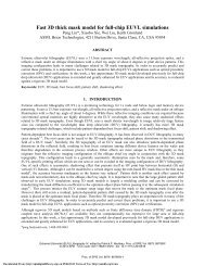
Figure 8 Exposure l<strong>at</strong>itude has a global maximum in Absorber height vs. Bias space. This maximum is shifted towards thicker<br />
absorbers <strong>and</strong> larger biases for broader illumin<strong>at</strong>ion settings NAσ for 27 nm <strong>node</strong> (left column, from top to bottom). The optimal<br />
absorber thickness is smaller for 22 nm lines than for 27 nm (bottom row).<br />
For NA=0.33 / σ=0.9/0.2, exposure l<strong>at</strong>itude <strong>of</strong> 22 nm dense lines was also calcul<strong>at</strong>ed (Figure 8, bottom right).The<br />
optimal absorber thickness becomes smaller for 22 nm <strong>node</strong> compared to 27 nm. Notice th<strong>at</strong> the same full physical resist<br />
model is used in both cases for the comparison reason, while on practice a resist with a smaller diffusion length will<br />
presumably be used for 22 nm <strong>imaging</strong>.<br />
The summary <strong>of</strong> the simul<strong>at</strong>ions is shown in Figure 9. The global absorber height <strong>and</strong> HV bias is shown for all cases.<br />
On practice there is no need to go to this global maximum for an acceptable <strong>imaging</strong> performance because the usage <strong>of</strong><br />
thick absorber requires also higher exposure dose [3] . But the values <strong>and</strong> trends show clearly th<strong>at</strong> there is no urgent need<br />
to go to smaller absorber height for 22 nm <strong>imaging</strong>, though HV shadowing bias compens<strong>at</strong>ion on mask in case <strong>of</strong> thick<br />
absorber is a requirement.<br />
Absorber height, nm<br />
120<br />
100<br />
80<br />
60<br />
40<br />
20<br />
0<br />
-20<br />
-40<br />
-60<br />
-80<br />
87<br />
95<br />
-7.3<br />
1.4<br />
-7.8 -1.3<br />
104<br />
7.5<br />
4.0<br />
96<br />
Conv 0.5 Conv 0.8 Conv 0.2 / 0.9 Conv 0.2 / 0.9<br />
NA=0.25 NA=0.25 NA=0.33<br />
3.0<br />
0.2<br />
27 nm 22 nm<br />
12.0<br />
10.0<br />
8.0<br />
6.0<br />
4.0<br />
2.0<br />
0.0<br />
-2.0<br />
-4.0<br />
-6.0<br />
-8.0<br />
Optimal bias, nm<br />
Optimal<br />
absorber<br />
height<br />
Optimal<br />
bias<br />
Vertical<br />
lines<br />
Optimal<br />
bias,<br />
Horizontal<br />
lines<br />
Figure 9 Absorber height, vertical <strong>and</strong> horizontal dense lines bias corresponding to maximal exposure l<strong>at</strong>itude.<br />
Proc. <strong>of</strong> SPIE Vol. 8166 816624-6<br />
Downloaded From: http://proceedings.spiedigitallibrary.org/ on 04/08/2013 Terms <strong>of</strong> Use: http://spiedl.org/terms