

lauren@kelman.ca
1YLWYxL
1YLWYxL

Create successful ePaper yourself
Turn your PDF publications into a flip-book with our unique Google optimized e-Paper software.
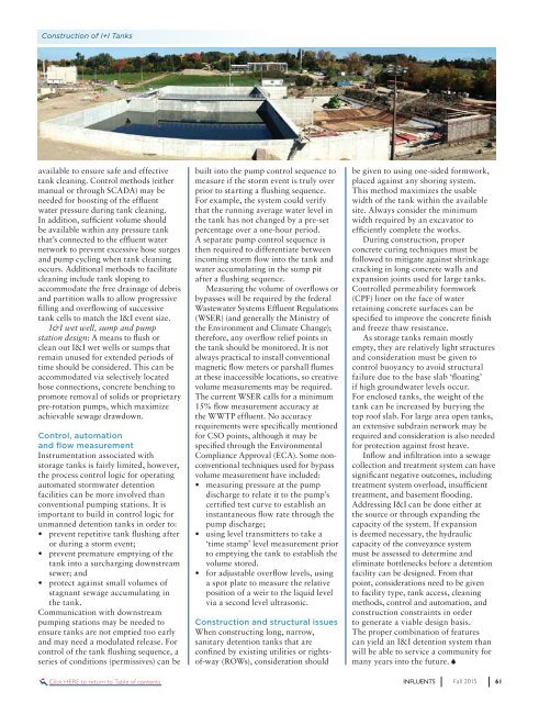
Construction of I+I Tanks<br />
available to ensure safe and effective<br />
tank cleaning. Control methods (either<br />
manual or through SCADA) may be<br />
needed for boosting of the effluent<br />
water pressure during tank cleaning.<br />
In addition, sufficient volume should<br />
be available within any pressure tank<br />
that’s connected to the effluent water<br />
network to prevent excessive hose surges<br />
and pump cycling when tank cleaning<br />
occurs. Additional methods to facilitate<br />
cleaning include tank sloping to<br />
accommodate the free drainage of debris<br />
and partition walls to allow progressive<br />
filling and overflowing of successive<br />
tank cells to match the I&I event size.<br />
I&I wet well, sump and pump<br />
station design: A means to flush or<br />
clean out I&I wet wells or sumps that<br />
remain unused for extended periods of<br />
time should be considered. This <strong>ca</strong>n be<br />
accommodated via selectively lo<strong>ca</strong>ted<br />
hose connections, concrete benching to<br />
promote removal of solids or proprietary<br />
pre-rotation pumps, which maximize<br />
achievable sewage drawdown.<br />
Control, automation<br />
and flow measurement<br />
Instrumentation associated with<br />
storage tanks is fairly limited, however,<br />
the process control logic for operating<br />
automated stormwater detention<br />
facilities <strong>ca</strong>n be more involved than<br />
conventional pumping stations. It is<br />
important to build in control logic for<br />
unmanned detention tanks in order to:<br />
• prevent repetitive tank flushing after<br />
or during a storm event;<br />
• prevent premature emptying of the<br />
tank into a surcharging downstream<br />
sewer; and<br />
• protect against small volumes of<br />
stagnant sewage accumulating in<br />
the tank.<br />
Communi<strong>ca</strong>tion with downstream<br />
pumping stations may be needed to<br />
ensure tanks are not emptied too early<br />
and may need a modulated release. For<br />
control of the tank flushing sequence, a<br />
series of conditions (permissives) <strong>ca</strong>n be<br />
built into the pump control sequence to<br />
measure if the storm event is truly over<br />
prior to starting a flushing sequence.<br />
For example, the system could verify<br />
that the running average water level in<br />
the tank has not changed by a pre-set<br />
percentage over a one-hour period.<br />
A separate pump control sequence is<br />
then required to differentiate between<br />
incoming storm flow into the tank and<br />
water accumulating in the sump pit<br />
after a flushing sequence.<br />
Measuring the volume of overflows or<br />
bypasses will be required by the federal<br />
Wastewater Systems Effluent Regulations<br />
(WSER) (and generally the Ministry of<br />
the Environment and Climate Change);<br />
therefore, any overflow relief points in<br />
the tank should be monitored. It is not<br />
always practi<strong>ca</strong>l to install conventional<br />
magnetic flow meters or parshall flumes<br />
at these inaccessible lo<strong>ca</strong>tions, so creative<br />
volume measurements may be required.<br />
The current WSER <strong>ca</strong>lls for a minimum<br />
15% flow measurement accuracy at<br />
the WWTP effluent. No accuracy<br />
requirements were specifi<strong>ca</strong>lly mentioned<br />
for CSO points, although it may be<br />
specified through the Environmental<br />
Compliance Approval (ECA). Some nonconventional<br />
techniques used for bypass<br />
volume measurement have included:<br />
• measuring pressure at the pump<br />
discharge to relate it to the pump’s<br />
certified test curve to establish an<br />
instantaneous flow rate through the<br />
pump discharge;<br />
• using level transmitters to take a<br />
‘time stamp’ level measurement prior<br />
to emptying the tank to establish the<br />
volume stored.<br />
• for adjustable overflow levels, using<br />
a spot plate to measure the relative<br />
position of a weir to the liquid level<br />
via a second level ultrasonic.<br />
Construction and structural issues<br />
When constructing long, narrow,<br />
sanitary detention tanks that are<br />
confined by existing utilities or rightsof-way<br />
(ROWs), consideration should<br />
be given to using one-sided formwork,<br />
placed against any shoring system.<br />
This method maximizes the usable<br />
width of the tank within the available<br />
site. Always consider the minimum<br />
width required by an ex<strong>ca</strong>vator to<br />
efficiently complete the works.<br />
During construction, proper<br />
concrete curing techniques must be<br />
followed to mitigate against shrinkage<br />
cracking in long concrete walls and<br />
expansion joints used for large tanks.<br />
Controlled permeability formwork<br />
(CPF) liner on the face of water<br />
retaining concrete surfaces <strong>ca</strong>n be<br />
specified to improve the concrete finish<br />
and freeze thaw resistance.<br />
As storage tanks remain mostly<br />
empty, they are relatively light structures<br />
and consideration must be given to<br />
control buoyancy to avoid structural<br />
failure due to the base slab ‘floating’<br />
if high groundwater levels occur.<br />
For enclosed tanks, the weight of the<br />
tank <strong>ca</strong>n be increased by burying the<br />
top roof slab. For large area open tanks,<br />
an extensive subdrain network may be<br />
required and consideration is also needed<br />
for protection against frost heave.<br />
Inflow and infiltration into a sewage<br />
collection and treatment system <strong>ca</strong>n have<br />
signifi<strong>ca</strong>nt negative outcomes, including<br />
treatment system overload, insufficient<br />
treatment, and basement flooding.<br />
Addressing I&I <strong>ca</strong>n be done either at<br />
the source or through expanding the<br />
<strong>ca</strong>pacity of the system. If expansion<br />
is deemed necessary, the hydraulic<br />
<strong>ca</strong>pacity of the conveyance system<br />
must be assessed to determine and<br />
eliminate bottlenecks before a detention<br />
facility <strong>ca</strong>n be designed. From that<br />
point, considerations need to be given<br />
to facility type, tank access, cleaning<br />
methods, control and automation, and<br />
construction constraints in order<br />
to generate a viable design basis.<br />
The proper combination of features<br />
<strong>ca</strong>n yield an I&I detention system than<br />
will be able to service a community for<br />
many years into the future.<br />
Click HERE to return to Table of contents<br />
INFLUENTS<br />
Fall 2015<br />
61