Conveying with ease Assembly, operating and insertion - Denipro
Conveying with ease Assembly, operating and insertion - Denipro
Conveying with ease Assembly, operating and insertion - Denipro

Create successful ePaper yourself
Turn your PDF publications into a flip-book with our unique Google optimized e-Paper software.
5 <strong>Assembly</strong> instructions<br />
Pl<strong>ease</strong> note:<br />
Geometrically, the conveying line must be correctly<br />
positioned for the denirug ® heavy-duty support to<br />
function reliably.<br />
denirug ® heavy-duty supports can be assembled in different<br />
ways (see sections 5.1 <strong>and</strong> 5.2). The following principles must<br />
be complied <strong>with</strong>:<br />
– Each denirug ® heavy-duty support is affi xed separately.<br />
– In accordance <strong>with</strong> the subsequent load, the base must<br />
be able to bear loads, horizontal <strong>and</strong> fl at. In the case<br />
of gravity conveying, minimum inclination is required<br />
<strong>and</strong> must be established by carrying out tests.<br />
– The distribution of the denirug ® heavy-duty supports is<br />
carefully planned separately according to the subsequent<br />
load distribution. The loads stated in the data sheets must<br />
not be exceeded. Support is often advisable in several<br />
tracks, where the heavy-duty supports are fi tted behind<br />
one another.<br />
– The supports must be fi tted precisely in the conveying<br />
direction. If there are several tracks, ensure they are<br />
parallel.<br />
– The supports are fi tted at the same height.<br />
Warning<br />
Before carrying out any assembly, maintenance<br />
<strong>and</strong> repairs, the conveyor drive’s master switch<br />
must be switched off <strong>and</strong> prevented from being<br />
switched on again.<br />
Where gravity conveyors are concerned,<br />
the area must be cordoned off appropriately<br />
<strong>and</strong> monitored.<br />
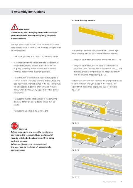
5.1 basic denirug ® element<br />
Basic denirug ® elements have drill holes (ø 12.5 mm) right<br />
across the body which allow different affi xation methods.<br />
– They can be affi xed <strong>with</strong> brackets on the base (fi g. 5. 1.1)<br />
– They can be affi xed <strong>with</strong> each other to form extensive<br />
structures, using threaded rods of appropriate sizes (1) <strong>and</strong><br />
tube sections (2). Sliding strips (3) are integrated directly<br />
into the structure if required (fi g. 5.1.2).<br />
Furthermore, basic denirug ® elements (for example in the case<br />
of slider beds) can simply be placed in the recesses. The<br />
support from below must be provided by a second base<br />
(fi g.5.1.3).<br />
Fig. 5.1.1<br />
Fig. 5.1.2<br />
Fig. 5.1.3<br />
➊<br />
➋<br />
➌<br />
DG_bma_EN_11.10<br />
4