isolated current voltage transducers

Create successful ePaper yourself
Turn your PDF publications into a flip-book with our unique Google optimized e-Paper software.
Hall Effect Technologies<br />
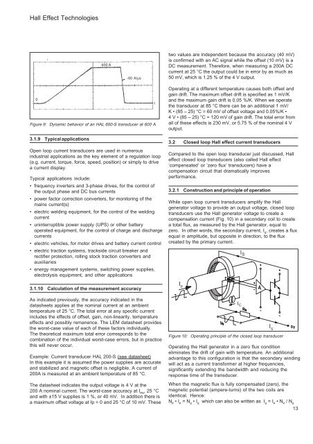
600 A<br />
-50 A/µs<br />
two values are independent because the accuracy (40 mV)<br />
is confirmed with an AC signal while the offset (10 mV) is a<br />
DC measurement. Therefore, when measuring a 200A DC<br />
<strong>current</strong> at 25 °C the output could be in error by as much as<br />
50 mV, which is 1.25 % of the 4 V output.<br />
0<br />
Figure 9: Dynamic behavior of an HAL 600-S transducer at 600 A<br />
3.1.9 Typical applications<br />
Open loop <strong>current</strong> <strong>transducers</strong> are used in numerous<br />
industrial applications as the key element of a regulation loop<br />
(e.g. <strong>current</strong>, torque, force, speed, position) or simply to drive<br />
a <strong>current</strong> display.<br />
Typical applications include:<br />
• frequency inverters and 3-phase drives, for the control of<br />
the output phase and DC bus <strong>current</strong>s<br />
• power factor correction converters, for monitoring of the<br />
mains <strong>current</strong>(s)<br />
• electric welding equipment, for the control of the welding<br />
<strong>current</strong><br />
• uninterruptible power supply (UPS) or other battery<br />
operated equipment, for the control of charge and discharge<br />
<strong>current</strong>s<br />
• electric vehicles, for motor drives and battery <strong>current</strong> control<br />
• electric traction systems, trackside circuit breaker and<br />
rectifier protection, rolling stock traction converters and<br />
auxiliaries<br />
• energy management systems, switching power supplies,<br />
electrolysis equipment, and other applications<br />
3.1.10 Calculation of the measurement accuracy<br />
As indicated previously, the accuracy indicated in the<br />
datasheets applies at the nominal <strong>current</strong> at an ambient<br />
temperature of 25 °C. The total error at any specific <strong>current</strong><br />
includes the effects of offset, gain, non-linearity, temperature<br />
effects and possibly remanence. The LEM datasheet provides<br />
the worst-case value of each of these factors individually.<br />
The theoretical maximum total error corresponds to the<br />
combination of the individual worst-case errors, but in practice<br />
this will never occur.<br />
Example: Current transducer HAL 200-S (see datasheet)<br />
In this example it is assumed the power supplies are accurate<br />
and stabilized and magnetic offset is negligible. A <strong>current</strong> of<br />
200A is measured at an ambient temperature of 85 °C.<br />
The datasheet indicates the output <strong>voltage</strong> is 4 V at the<br />
200 A nominal <strong>current</strong>. The worst-case accuracy at I PN<br />
, 25 °C<br />
and with ±15 V supplies is 1 %, or 40 mV. In addition there is<br />
a maximum offset <strong>voltage</strong> at Ip = 0 and 25 °C of 10 mV. These<br />
Operating at a different temperature causes both offset and<br />
gain drift. The maximum offset drift is specified as 1 mV/K<br />
and the maximum gain drift is 0.05 %/K. When we operate<br />
the transducer at 85 °C there can be an additional 1 mV/<br />
K • (85 – 25) °C = 60 mV of offset <strong>voltage</strong> and 0.05%/K •<br />
4 V • (85 – 25) °C = 120 mV of gain drift. The total error from<br />
all of these effects is 230 mV, or 5.75 % of the nominal 4 V<br />
output.<br />
3.2 Closed loop Hall effect <strong>current</strong> <strong>transducers</strong><br />
Compared to the open loop transducer just discussed, Hall<br />
effect closed loop <strong>transducers</strong> (also called Hall effect<br />
‘compensated’ or ‘zero flux’ <strong>transducers</strong>) have a<br />
compensation circuit that dramatically improves<br />
performance.<br />
3.2.1 Construction and principle of operation<br />
While open loop <strong>current</strong> <strong>transducers</strong> amplify the Hall<br />
generator <strong>voltage</strong> to provide an output <strong>voltage</strong>, closed loop<br />
<strong>transducers</strong> use the Hall generator <strong>voltage</strong> to create a<br />
compensation <strong>current</strong> (Fig. 10) in a secondary coil to create<br />
a total flux, as measured by the Hall generator, equal to<br />
zero. In other words, the secondary <strong>current</strong>, I S<br />
, creates a flux<br />
equal in amplitude, but opposite in direction, to the flux<br />
created by the primary <strong>current</strong>.<br />
I P<br />
I P<br />
Figure 10: Operating principle of the closed loop transducer<br />
Operating the Hall generator in a zero flux condition<br />
eliminates the drift of gain with temperature. An additional<br />
advantage to this configuration is that the secondary winding<br />
will act as a <strong>current</strong> transformer at higher frequencies,<br />
significantly extending the bandwidth and reducing the<br />
response time of the transducer.<br />
When the magnetic flux is fully compensated (zero), the<br />
magnetic potential (ampere-turns) of the two coils are<br />
identical. Hence:<br />
N P<br />
• I P<br />
= N S<br />
• I S<br />
which can also be written as I S<br />
= I P<br />
• N P<br />
/ N S<br />
13<br />
I C<br />
I S<br />
I S<br />
I S