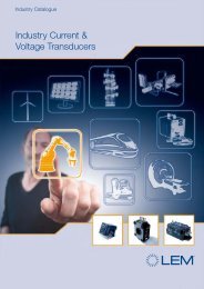
isolated current voltage transducers

You also want an ePaper? Increase the reach of your titles
YUMPU automatically turns print PDFs into web optimized ePapers that Google loves.
Voltage Transducers and Basic Working Principle<br />
2 Determining parameters for transducer<br />
selection<br />
The wide variety of available LEM <strong>transducers</strong> is the direct<br />
result of our know-how and many years of experience,<br />
enabling us to address the many variations of customer<br />
requirements within the greatly diversified field of power<br />
electronics. The application requirements create selection<br />
criteria, guiding the user to an appropriate product.<br />
2.1 Which parameters need to be considered?<br />
The selection of a transducer is the result of a technical and<br />
economic trade-off, considering the transducer as well as<br />
the associated sub-systems. All aspects of an application<br />
must therefore be taken into account during transducer<br />
selection and system design, with particular attention to the<br />
following:<br />
• electrical requirements, including power supply<br />
requirements, peak measurement, response time, di/dt,<br />
dv/dt, etc.<br />
• mechanical requirements, including aperture size, overall<br />
dimensions, mass, materials, mounting, etc.<br />
• thermal conditions, including <strong>current</strong> profile versus time,<br />
maximum RMS measurement, thermal resistances,<br />
cooling, etc.<br />
• environmental conditions, including vibration,<br />
temperature, proximity of other conductors or magnetic<br />
fields, etc.<br />
The transducer development process includes a full regimen<br />
of tests that comprise the characterization report. These tests<br />
follow the scientific method, varying individual parameters to<br />
characterize the <strong>transducers</strong> response to each.<br />
During production a quality plan indicates the tests to be<br />
carried out, on each product or batch of products, to verify<br />
compliance with specifications. Unless otherwise specified,<br />
performance is tested under nominal conditions of <strong>current</strong>,<br />
<strong>voltage</strong>, temperature, etc. in the production and laboratory<br />
environments.<br />
In the actual application, several factors can act simultaneously<br />
and potentially provide unexpected results. It is<br />
essential to assess the transducer in those conditions to<br />
verify acceptable performance. Based on LEM experiences,<br />
this assessment is typically not difficult if the working<br />
conditions are known and defined.<br />
2.2 Understanding the LEM documentation<br />
The first step for transducer selection is a detailed understanding<br />
of the application, including parameters such as<br />
continuous RMS and repetitive peak measurement level,<br />
maximum possible peak or fault level, rate of change<br />
(e.g. di/dt and dv/dt) to be measured, allowable response<br />
time, etc. One must also consider external influences that<br />
will impact the application, such as temperature, shock,<br />
vibration, and external fields as well as any necessary<br />
compliance standards (EN, IEC, UL, CSA, etc.) that need to<br />
be met.<br />
Using this information, refer to the general catalog of LEM<br />
<strong>transducers</strong> to locate the product line(s) that have the key<br />
characteristics to meet the requirements from the full range<br />
of available products. Then select the specific product(s)<br />
from those lines that meet the measurement requirements.<br />
The individual datasheet (see the LEM website: http://<br />
www.lem.com) of the selected transducer(s) will then<br />
provide more details to determine if the transducer(s) match<br />
the requirements. The checklist provided in the following<br />
tables (§2.4 and §2.5) may help define critical concerns and<br />
assist in the transducer selection process.<br />
2.3 Additional selection criteria<br />
As previously discussed, some applications have a higher<br />
level of complexity and combine several potentially critical<br />
elements such as:<br />
• electromagnetic interference<br />
• significant common mode <strong>voltage</strong> transients (dv/dt)<br />
• mechanical disturbances (vibration, shock, etc.)<br />
• special isolation or partial discharge requirements<br />
• compliance with specific standards, etc.<br />
Obviously the best scenario is to perform tests in the specific<br />
application environment. If this is not reasonable or feasible,<br />
provide LEM with a diagram of your installation and a<br />
detailed description of the transducer operating conditions<br />
(e.g. description of the environmental conditions, graph of<br />
the waveform to be measured, nearby potentially disturbing<br />
elements such as inductors, <strong>current</strong> carrying conductors, the<br />
presence of magnetic materials or the desired location of<br />
other <strong>transducers</strong>).<br />
The operating temperature range is based on the materials<br />
and construction of the selected transducer. The minimum<br />
temperatures are typically -40, -25, or -10 °C while the<br />
maximums are +50, +70, +85, or +105 °C.<br />
5