isolated current voltage transducers

Create successful ePaper yourself
Turn your PDF publications into a flip-book with our unique Google optimized e-Paper software.
Air-Core Technologies<br />
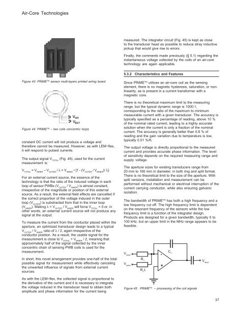
measured. The integrator circuit (Fig. 45) is kept as close<br />
to the transducer head as possible to reduce stray inductive<br />
pickup that would give rise to errors.<br />
Finally, the comments made previously (§ 5.1) regarding the<br />
instantaneous <strong>voltage</strong> collected by the coils of an air-core<br />
technology are again applicable.<br />
5.3.2 Characteristics and Features<br />
Figure 43: PRiME TM sensor multi-layers printed wiring board<br />
Figure 44: PRiME TM – two coils concentric loops<br />
constant DC <strong>current</strong> will not produce a <strong>voltage</strong> and<br />
therefore cannot be measured. However, as with LEM~flex,<br />
it will respond to pulsed <strong>current</strong>s.<br />
The output signal V TOTAL<br />
(Fig. 45), used for the <strong>current</strong><br />
measurement is:<br />
V TOTAL<br />
= V INNER<br />
– V OUTER<br />
/ λ = V INNER<br />
• [1 - (V OUTER<br />
/ V INNER<br />
)/ λ]<br />
For an external <strong>current</strong> source, the essence of the<br />
technology is that the ratio of the induced <strong>voltage</strong> in each<br />
loop of sensor PWBs (V OUTER<br />
/ V INNER<br />
) is almost constant,<br />
irrespective of the magnitude or position of this external<br />
source. As a result, the external field effects are cancelled if<br />
the correct proportion of the <strong>voltage</strong> induced in the outer<br />
loop (V OUTER<br />
) is substracted from that in the inner loop<br />
(V INNER<br />
). Making λ = V OUTER<br />
/ V INNER<br />
will force V TOTAL<br />
= 0 or, in<br />
other words, an external <strong>current</strong> source will not produce any<br />
signal at the output.<br />
To measure the <strong>current</strong> from the conductor placed within the<br />
aperture, an optimized transducer design leads to a typical<br />
V OUTER<br />
/ V INNER<br />
ratio of λ / 2, again irrespective of the<br />
conductor position. As a result, the usable signal for the<br />
measurement is close to V TOTAL<br />
= V INNER<br />
/ 2, meaning that<br />
approximately half of the signal collected by the inner<br />
concentric chain of sensing PWB coils is used for the<br />
measurement.<br />
In short, this novel arrangement provides one-half of the total<br />
possible signal for measurement while effectively canceling<br />
the unwanted influence of signals from external <strong>current</strong><br />
sources.<br />
As with the LEM~flex, the collected signal is proportional to<br />
the derivative of the <strong>current</strong> and it is necessary to integrate<br />
the <strong>voltage</strong> induced in the transducer head to obtain both<br />
amplitude and phase information for the <strong>current</strong> being<br />
Since PRiME TM utilizes an air-core coil as the sensing<br />
element, there is no magnetic hysteresis, saturation, or nonlinearity,<br />
as is present in a <strong>current</strong> transformer with a<br />
magnetic core.<br />
There is no theoretical maximum limit to the measuring<br />
range, but the typical dynamic range is 1000:1,<br />
corresponding to the ratio of the maximum to minimum<br />
measurable <strong>current</strong> with a given transducer. The accuracy is<br />
typically specified as a percentage of reading, above 10 %<br />
of the nominal rated <strong>current</strong>, leading to a highly accurate<br />
solution when the <strong>current</strong> is only a fraction of the nominal<br />
<strong>current</strong>. The accuracy is generally better than 0.8 % of<br />
reading and the gain variation due to temperature is low,<br />
typically 0.01 %/K.<br />
The output <strong>voltage</strong> is directly proportional to the measured<br />
<strong>current</strong> and provides accurate phase information. The level<br />
of sensitivity depends on the required measuring range and<br />
supply <strong>voltage</strong>.<br />
The aperture sizes for existing <strong>transducers</strong> range from<br />
20 mm to 160 mm in diameter, in both ring and split format.<br />
There is no theoretical limit to the size of the aperture. With<br />
split versions, installation and measurement can be<br />
performed without mechanical or electrical interruption of the<br />
<strong>current</strong> carrying conductor, while also ensuring galvanic<br />
isolation.<br />
The bandwidth of PRiME TM has both a high frequency and a<br />
low frequency cut off. The high frequency limit is dependent<br />
on the resonant frequency of the sensors while the low<br />
frequency limit is a function of the integrator design.<br />
Products are designed for a given bandwidth, typically 5 to<br />
100 kHz, but an upper limit in the MHz range appears to be<br />
feasible.<br />
V inner<br />
V outer<br />
R 1<br />
R 1<br />
λ<br />
Figure 45: PRiME TM – processing of the coil signals<br />
-<br />
+<br />
C f<br />
V total<br />
37