

NTN - Large Bearings

Create successful ePaper yourself
Turn your PDF publications into a flip-book with our unique Google optimized e-Paper software.
Cylindrical Roller <strong>Bearings</strong><br />
2. Dimensional Accuracy/Rotation Accuracy<br />
Refer to Table 3.3 (Page A-12,13)<br />
3. Recommended Fitting<br />
Refer to Table 4.2 (Page A-24)<br />
4. Bearing Internal Clearance<br />
Refer to Table 5.5 and 5.6 (Page A-31, 32, 33)<br />
5. Permissible slant angle<br />
It varies according to the bearing type and internal<br />
specifications, the values in the table below are widely<br />
used to avoid edge loads under general load conditions.<br />
When the width series is 0 or 1 ⋯⋯0.001 rad (3.5')<br />
When the width series is 2 ⋯⋯⋯⋯0.0005 rad (1.5')<br />
Double row cylindrical roller bearing 1 ⋯0.0005 rad (1.5')<br />
1 This is no applied to high accuracy bearings which are<br />
used as the main shaft of machine tools.<br />
Table 5 Tolerance of inscribed circle diameter Fw of rollers and<br />
circumscribed circle diameter Ew of rollers for<br />
compatible bearings.<br />
Unit m<br />
d mm ∆Fw ∆Ew<br />
over Incl high low<br />
50<br />
120<br />
200<br />
250<br />
315<br />
400<br />
500<br />
630<br />
800<br />
1,000<br />
1,250<br />
120<br />
200<br />
250<br />
315<br />
400<br />
500<br />
630<br />
800<br />
1,000<br />
1,250<br />
1,400<br />
+ 20<br />
+ 25<br />
+ 30<br />
+ 35<br />
+ 40<br />
+ 45<br />
+ 70<br />
+ 80<br />
+ 90<br />
+105<br />
+125<br />
- 20<br />
- 25<br />
- 30<br />
- 35<br />
- 40<br />
- 45<br />
- 70<br />
- 80<br />
- 90<br />
-105<br />
-125<br />
∆FwDimensional difference of inscribed circle diameter of rollers. 2<br />
∆EwDimensional difference of circumscribed circle diameter of rollers. 2<br />
2 Regulation range of JIS is d 500mm for ∆Fw, and d 400mm for ∆Ew.<br />
0<br />
0<br />
0<br />
0<br />
0<br />
0<br />
0<br />
0<br />
0<br />
0<br />
0<br />
low<br />
0<br />
0<br />
0<br />
0<br />
0<br />
0<br />
0<br />
0<br />
0<br />
0<br />
0<br />
high<br />
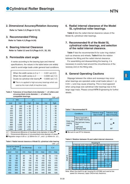
Table 6 Radial internal clearance of Model SL cylindrical roller bearing.<br />
Unit m<br />
Nominal bore diameter<br />
CN (Normal) C 3 C 4<br />
dmm<br />
over Incl min max min max min max<br />
30 50 20 75 40 95 55 110<br />
50 80 30 90 55 115 75 135<br />
80 120 35 105 80 150 105 175<br />
120 180 60 150 110 200 150 240<br />
180 250 90 190 155 255 205 305<br />
250 315 110 225 195 310 255 370<br />
315 400 140 265 245 370 320 445<br />
400 500 180 320 300 440 395 535<br />
6. Radial internal clearance of the Model<br />
SL cylindrical roller bearings.<br />
Table 6 lists the radial internal clearance values of the<br />
Model SL cylindrical roller bearings.<br />
7. Recommended fit of the Model SL<br />
cylindrical roller bearings, and selection<br />
of the radial internal clearance.<br />
Table 7 lists the recommended fit for outer ring rotation<br />
such as sheaves and wheels, Table 8 lists the relation<br />
between the fitting and the radial internal clearance.<br />
For assembling and disassembling the bearing, it is<br />
necessary to evenly load around the circumference of the<br />
raceway end on the fitting side.<br />
8. General Operating Cautions<br />
Slippage between the rollers and raceways may occur<br />
when bearings are operated under small loads (about Fr <br />
0.04Cor) and may cause smearing. This is most apparent<br />
when using large size cylindrical roller bearings due to the<br />
large cage mass. Please consult <strong>NTN</strong> Engineering for further<br />
details.<br />
Table 7 Recommended fit<br />
Outer ring<br />
rotating<br />
load<br />
Conditions<br />
Heavy load with a<br />
thin walled housing.<br />
Normal load, heavy<br />
load<br />
Light load,<br />
changing load<br />
3 Be sure to use N7 for sheaves.<br />
Tolerance range<br />
class of shaft<br />
g6 or h6<br />
Tolerance range<br />
class of housing<br />
P7<br />
3<br />
N7<br />
M7<br />
Table 8 Relation between fit and radial internal clearance.<br />
Shaft fit<br />
g 6<br />
h 6<br />
j 5<br />
j 6<br />
k 5<br />
k 6<br />
m 5<br />
m 6<br />
n 5<br />
n 6<br />
p 6<br />
Housing fit<br />
G 7 H 6 J 6 J 7 K 6 K 7 g 6 M 6 M 7 N 6 N 7 P 6 P 7<br />
CN(Normal) C 3<br />
C 3<br />
C 4<br />
C 4<br />
Note: When the shaft fit is g6, housing fit is N7(N6) and used at low<br />
speed (for sheaves), apply CN(normal) clearance.<br />
B-39


