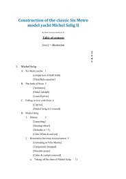
Michel Selig II
The Construction of The Classic Six Metre Model Yacht Michel Selig II
The Construction of The Classic Six Metre Model Yacht Michel Selig II

Create successful ePaper yourself
Turn your PDF publications into a flip-book with our unique Google optimized e-Paper software.
the sternpost<br />
c. Drawing station lines on the sides of the "half" lifts<br />
In preparing the plans for cutting, station lines had been<br />
drawn on the top and bottom of the lifts. During the<br />
carving phase, station lines are needed on the outer and<br />
inner sides of the boat.<br />
This meant connecting the station lines on the top of a<br />
half lift with those on the bottom. Disappointingly, the<br />
lines rarely lined up completely. There was usually a<br />
discrepancy of 1 - 2 mm. - and sometimes much more.<br />
This led to drawing lines of three colours:<br />
- blue: for the initial linking of the top and bottom<br />
lines, i.e. one half lift at a time,<br />
- green: for resolving discrepancies between the blue<br />
lines on both the inner and outer sides of the two<br />
halves of the lift, i.e. two half lifts at a time,<br />
- red: for defining a definitive station line on the<br />
outside of the hull over all the lifts (after gluing the<br />
lifts together).<br />
Drawing the station lines on the sides of a half lift.<br />
They should correspond to the station lines on the top<br />
and bottom of the lifts. One can see that they don't.<br />
The square ensures that the lines will be<br />
perpendicular.<br />
The next step was to verify that the station lines of the<br />
two half lifts are in alignment.