


You also want an ePaper? Increase the reach of your titles
YUMPU automatically turns print PDFs into web optimized ePapers that Google loves.
Tutorial<br />
STEP BY STEP<br />
ROB ZWETSLOOT<br />
Tinkerer, sometime maker,<br />
other-times cosplayer, and<br />
all-the-time features editor<br />
of The MagPi.<br />
magpi.cc / @TheMagP1<br />
PISPY CAM<br />
Set up a motion-activated spy camera in your room to find out<br />
You’ll<br />
Need<br />
> Pi Zero<br />
> PIR motion<br />
sensor<br />
magpi.cc/<br />
2gCQKPj<br />
> Raspberry Pi<br />
Camera Module<br />
magpi.cc/28IjIsz<br />
> Pi Zero camera<br />
cable adapter<br />
magpi.cc/<br />
2gT2KwE<br />
> Portable battery<br />
if anyone’s coming in when you’re not there<br />
W<br />
e’ve all been there. You’ve gone out for the day<br />
and you know you closed your bedroom door,<br />
but you come back and it’s slightly ajar. Who’s<br />
been in there? Were they friend or foe?<br />
>STEP-01<br />
Connect up the camera<br />
Attaching the camera to the Raspberry Pi Zero is easy,<br />
and if you read our camera beginner’s guide you’ll<br />
already have an idea. You’ll need to first switch out the<br />
cable in the Camera Module with the adapter for the<br />
Pi Zero. Gently pull down on the clasp that keeps the<br />
ribbon on the Camera Module attached and remove<br />
the cable. Take note of the orientation of the silver<br />
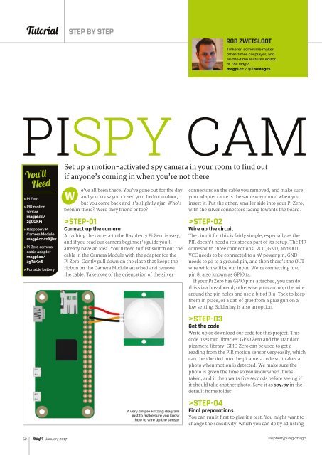
A very simple Fritzing diagram<br />
just to make sure you know<br />
how to wire up the sensor<br />
connectors on the cable you removed, and make sure<br />
your adapter cable is the same way round when you<br />
insert it. Put the other, smaller side into your Pi Zero,<br />
with the silver connectors facing towards the board.<br />
>STEP-02<br />
Wire up the circuit<br />
The circuit for this is fairly simple, especially as the<br />
PIR doesn’t need a resistor as part of its setup. The PIR<br />
comes with three connections: VCC, GND, and OUT.<br />
VCC needs to be connected to a 5V power pin, GND<br />
needs to go to a ground pin, and then there’s the OUT<br />
wire which will be our input. We’re connecting it to<br />
pin 8, also known as GPIO 14.<br />
If your Pi Zero has GPIO pins attached, you can do<br />
this via a breadboard; otherwise you can loop the wire<br />
around the pin holes and use a bit of Blu-Tack to keep<br />
them in place, or a dab of glue from a glue gun on a<br />
low setting. Soldering is also an option.<br />
>STEP-03<br />
Get the code<br />
Write up or download our code for this project. This<br />
code uses two libraries: GPIO Zero and the standard<br />
picamera library. GPIO Zero can be used to get a<br />
reading from the PIR motion sensor very easily, which<br />
can then be tied into the picamera code so it takes a<br />
photo when motion is detected. We make sure the<br />
photo is given the time so you know when it was<br />
taken, and it then waits five seconds before seeing if<br />
it should take another photo. Save it as spy.py in the<br />
default home folder.<br />
>STEP-04<br />
Final preparations<br />
You can run it first to give it a test. You might want to<br />
change the sensitivity, which you can do by adjusting<br />
62 January 2017<br />
raspberrypi.org/magpi