PLIN-Slave - User Manual - PEAK-System
PLIN-Slave - User Manual - PEAK-System
PLIN-Slave - User Manual - PEAK-System

Create successful ePaper yourself
Turn your PDF publications into a flip-book with our unique Google optimized e-Paper software.
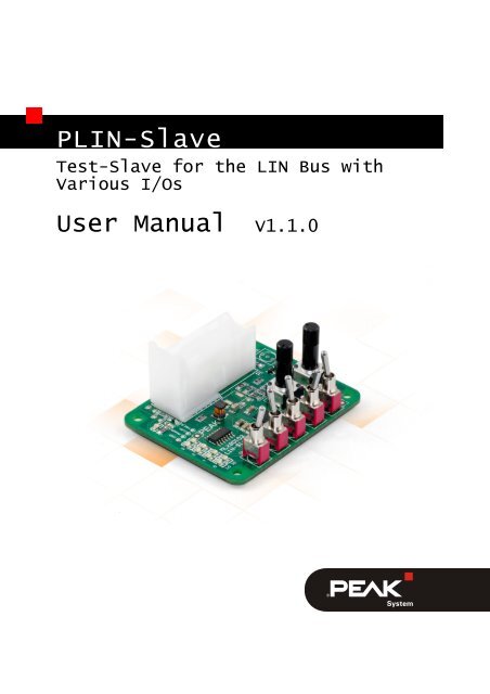
<strong>PLIN</strong>-<strong>Slave</strong><br />
Test-<strong>Slave</strong> for the LIN Bus with<br />
Various I/Os<br />
<strong>User</strong> <strong>Manual</strong> V1.1.0
<strong>PLIN</strong>-<strong>Slave</strong> – <strong>User</strong> <strong>Manual</strong><br />
Products taken into account<br />
Product name Model Part number<br />
<strong>PLIN</strong>-<strong>Slave</strong> Eval-Board IPEH-004050<br />
All product names mentioned in this document may be the trademarks or registered<br />
trademarks of their respective companies. They are not explicitly marked by “” or<br />
“®”.<br />
© 2012 <strong>PEAK</strong>-<strong>System</strong> Technik GmbH<br />
<strong>PEAK</strong>-<strong>System</strong> Technik GmbH<br />
Otto-Roehm-Straße 69<br />
64293 Darmstadt<br />
Germany<br />
Phone: +49 (0)6151 8173-20<br />
Fax: +49 (0)6151 8173-29<br />
www.peak-system.com<br />
info@peak-system.com<br />
Document version 1.1.0 2012-05-29<br />
2
<strong>PLIN</strong>-<strong>Slave</strong> – <strong>User</strong> <strong>Manual</strong><br />
Contents<br />
1 Introduction 4<br />
1.1 Properties at a Glance 4<br />
1.2 <strong>System</strong> Requirements 5<br />
1.3 Scope of Supply 5<br />
2 Operation 6<br />
2.1 Pin Assignment 6<br />
2.1.1 LIN Bus 7<br />
2.1.2 Digital Inputs 7<br />
2.1.3 Analog Inputs 7<br />
2.1.4 Digital Outputs 8<br />
2.2 Status LEDs 8<br />
2.3 Programming the Chip Properties 8<br />
2.4 Multiple <strong>PLIN</strong>-<strong>Slave</strong>s on LIN Bus 9<br />
3 LIN Communication 10<br />
3.1 <strong>PLIN</strong>-<strong>Slave</strong> Query Inputs 10<br />
3.2 <strong>PLIN</strong>-<strong>Slave</strong> Setting Outputs 11<br />
3.3 Predefined LIN IDs 11<br />
4 Operation 12<br />
5 Technical Specifications 13<br />
Appendix A Dimension Drawing 14<br />
3
<strong>PLIN</strong>-<strong>Slave</strong> – <strong>User</strong> <strong>Manual</strong><br />
1 Introduction<br />
The <strong>PLIN</strong>-<strong>Slave</strong> is an evaluation board with an interface for a LIN 2.0<br />
bus. The device also has comprehensive I/O functionality which is<br />
accessible through control and display elements.<br />
The PIN-<strong>Slave</strong> is used in development and education, for example,<br />
for testing purpose or as a teaching aid for handling the LIN<br />
protocol.<br />
The device is immediately ready for operation, a change of<br />
configuration or programming is neither necessary nor intended (no<br />
support).<br />
1.1 Properties at a Glance<br />
Supply voltage: 7 - 18 V<br />
Based on Melexis MLX80103<br />
1 LIN bus (v2.0), 19200 bit/s<br />
5 digital inputs (low-active), already occupied<br />
3 analog inputs (up to 18 V), already occupied<br />
4 digital outputs (low-active), 500 mA each<br />
4 digital outputs (high-active), 500 mA each<br />
Extended operating temperature range from -40 to 85 °C<br />
(-40 to 185 °F)<br />
4
<strong>PLIN</strong>-<strong>Slave</strong> – <strong>User</strong> <strong>Manual</strong><br />
1.2 <strong>System</strong> Requirements<br />
Note: A support to this topic can not be offered, because of the<br />
various network topologies, user interfaces, and configuration<br />
options.<br />
LIN network with a terminated master node.<br />
An existing LIN description file<br />
The supplied node capability file of the <strong>PLIN</strong>-<strong>Slave</strong> needs<br />
to be integrated into the LIN description file<br />
1.3 Scope of Supply<br />
<strong>PLIN</strong>-<strong>Slave</strong> including mating connector<br />
<strong>Manual</strong> in PDF format<br />
5
<strong>PLIN</strong>-<strong>Slave</strong> – <strong>User</strong> <strong>Manual</strong><br />
2 Operation<br />
To supply the <strong>PLIN</strong>-<strong>Slave</strong>, a voltage of 12 V is recommended,<br />
7 - 18 V are possible (similar to the electrical system in the car). The<br />
current consumption of the device is about 60 mA in operation. In<br />
this version the <strong>PLIN</strong>-<strong>Slave</strong> has all control elements onboard. The<br />
external circuit of the connector is reduced to the supply voltage<br />
GND (pin 14), Vbat (pin 26) and the LIN bus (pin 22).<br />
Note: Wiring the other pins (particularly Ain and Din) with additional<br />
components could cause short circuits and can damage<br />
the device permanently.<br />
2.1 Pin Assignment<br />
An overview of pin assignments of the connector, see the following<br />
table:<br />
Figure 1: Pin assignments of connector<br />
6
<strong>PLIN</strong>-<strong>Slave</strong> – <strong>User</strong> <strong>Manual</strong><br />
Pin Description Direction Meaning<br />
1, 2, 3, 4 DoutL-0…3 Output Low-active, only for measurement<br />
purposes<br />
5, 6, 7, 8, 9 Din-0...4 Input DO NOT connect externally<br />
10, 11, 12, 13 DoutH-0…3 Output High-active, only for measurement<br />
purposes<br />
14, 15, 16 GND Input Supply voltage, one of them needed<br />
for operation<br />
17 Analog GND Input DO NOT connect externally<br />
18, 19, 20 Ain-0...2 Input DO NOT connect externally<br />
21, 22 LIN Bidirectional LIN bus, one of them needed for<br />
operation<br />
23 EOL Input Programming mode,<br />
DO NOT use<br />
24, 25, 26 Vbat Input Supply voltage, one of them needed<br />
for operation<br />
2.1.1 LIN Bus<br />
The <strong>PLIN</strong>-<strong>Slave</strong> is connected to a LIN network as a slave node. The<br />
LIN master of this network reads out the positions of the 5 switches<br />
(Din-0...4) and potentiometers (Ain-0 and 1) as well as the applied<br />
power supply (Ain-2). Furthermore it sets the 8 LEDs (DoutL-0...3,<br />
DoutH-0...3). The necessary LIN messages are described in the<br />
attached file <strong>PLIN</strong>-<strong>Slave</strong>.ncf (ncf = node capability file).<br />
2.1.2 Digital Inputs<br />
The 5 digital inputs of the <strong>PLIN</strong>-<strong>Slave</strong> are already equipped with<br />
switches.<br />
2.1.3 Analog Inputs<br />
The 3 analog inputs of the <strong>PLIN</strong>-<strong>Slave</strong> are connected on the board.<br />
Ain-0 and Ain-1 are adjustable via potentiometer, Ain-2 digitalizes<br />
the applied supply voltage.<br />
7
<strong>PLIN</strong>-<strong>Slave</strong> – <strong>User</strong> <strong>Manual</strong><br />
2.1.4 Digital Outputs<br />
The lead-out pins can be used for measurement purposes. The<br />
digital outputs are connected with 8 LEDs on the board for the<br />
visualization (see the following chapter 2.2).<br />
Note: The lead-out pins of the digital inputs/outputs as well as<br />
the analog inputs must not be wired with additional components,<br />
because this can cause short circuits or the destruction<br />
of the device.<br />
2.2 Status LEDs<br />
LED Status Meaning<br />
Power Green on Voltage supply is connected<br />
DoutL-0..3 Red on Set via message Control_xxx_LIN<br />
DoutH-0..3 Green on Set via message Control_xxx_LIN<br />
2.3 Programming the Chip Properties<br />
The <strong>PLIN</strong>-<strong>Slave</strong> is programmed with a basic configuration ex<br />
factory, that is well suited for the intended purpose of<br />
demonstration and education. Reprogramming of the properties is<br />
only possible with good knowledge of the used LIN master node<br />
(respectively its operating software) and the data sheet 1 for Melexis<br />
MLX80103. Support for this can not be offered, because of the<br />
various network topologies, user interfaces, and configuration<br />
options.<br />
1 The data sheet of Melexis MLX80103 can be requested on: www.melexis.de<br />
8
<strong>PLIN</strong>-<strong>Slave</strong> – <strong>User</strong> <strong>Manual</strong><br />
2.4 Multiple <strong>PLIN</strong>-<strong>Slave</strong>s on LIN Bus<br />
LIN IDs can be changed by Assign frame ID. The procedure for<br />
this is described in the data sheet 1 for Melexis MLX80103.<br />
9
<strong>PLIN</strong>-<strong>Slave</strong> – <strong>User</strong> <strong>Manual</strong><br />
3 LIN Communication<br />
3.1 <strong>PLIN</strong>-<strong>Slave</strong> Query Inputs<br />
To query the inputs (control elements: switches and potentiometers)<br />
a LIN frame with the following properties of <strong>PLIN</strong>-<strong>Slave</strong> must<br />
be requested by the LIN master:<br />
Description Meaning<br />
Name Status_xxx_LIN<br />
LIN-ID 1<br />
Direction Subscriber<br />
Data length 8<br />
Checksum type Enhanced<br />
Time Cyclical, e.g. 50 ms<br />
The data in the LIN frame Status_xxx_LIN (see also file *.ncf) is<br />
arranged as follows:<br />
Byte<br />
7 Ain-2 (= Vbat)<br />
6 Ain-1<br />
5 Ain-0<br />
4 DoutL-3 DoutH-3 DoutH-2 DoutH-1 DoutH-0 1<br />
3 1 1 1 1 1 1 1 1<br />
2 1 1 1 1 1 1 Din-4 Din-<br />
3<br />
1<br />
0<br />
Din-2 Din-1 Din-0 1 1<br />
10
<strong>PLIN</strong>-<strong>Slave</strong> – <strong>User</strong> <strong>Manual</strong><br />
3.2 <strong>PLIN</strong>-<strong>Slave</strong> Setting Outputs<br />
For setting the outputs (LEDs) a LIN frame with the following<br />
properties of <strong>PLIN</strong>-<strong>Slave</strong> must be requested by the LIN master:<br />
Description Meaning<br />
Name Control_xxx_LIN<br />
LIN-ID 5<br />
Direction Publisher<br />
Data length 2<br />
Checksum type Enhanced<br />
Time If needed<br />
The data in the LIN frame Control_xxx_LIN (see also file *.ncf) is<br />
arranged as follows:<br />
Byte<br />
1 DoutL-3 DoutH-3 DoutH-2 DoutH-1 DoutH-0<br />
0 DoutL-2 DoutL-1 DoutL-0<br />
3.3 Predefined LIN IDs<br />
Direction Publisher and Subscriber each from the view of the<br />
controlling LIN master node.<br />
Master asks, LIN answers:<br />
LIN ID Message ID Length Type Checksum Name<br />
1 0x0001 8 Subscriber Enhanced Status_xxx_LIN<br />
Master transmits command to slave:<br />
LIN ID Message ID Length Type Checksum Name<br />
5 0x8002 2 Publisher Enhanced Control_xxx_LIN<br />
11
<strong>PLIN</strong>-<strong>Slave</strong> – <strong>User</strong> <strong>Manual</strong><br />
4 Operation<br />
The <strong>PLIN</strong>-<strong>Slave</strong> is equipped with a number of control elements, that<br />
can display the main features of the device.<br />
Figure 2: View of control elements<br />
Connector incl. assignment of the pin numbers<br />
(see section 2.1 Pin Assignment on page 6)<br />
5 switches for controlling Din-0...4<br />
(see section 2.1.2 Digital Inputs on page 7)<br />
2 potentiometers of Ain-0...1<br />
(see section 2.1.3 Analog Inputs on page 7)<br />
8 LEDs for representing DoutL-0...3 and DoutH-0...3<br />
(see section 2.1.4 Digital Outputs on page 8)<br />
Power LED to indicate the supply voltage<br />
(see section 2.2 Status LEDs on page 8)<br />
12
<strong>PLIN</strong>-<strong>Slave</strong> – <strong>User</strong> <strong>Manual</strong><br />
5 Technical Specifications<br />
Power supply<br />
Supply voltage 7 - 18 V<br />
Current consumption 60 mA<br />
Inverse-polarity protection yes<br />
Overvoltage protection yes<br />
LIN<br />
Bus voltage 7 - 18 V<br />
Bit rate 19200 bits/s<br />
Protocol Version 2.0<br />
Transceiver Melexis MLX80103<br />
Measures<br />
Size 70 x 57 x 28 mm (B x H x T)<br />
See also dimension drawing Appendix A on<br />
page 14<br />
Weight 50 g<br />
Environment<br />
Operating temperature -40 - +85 °C<br />
Temperature for storage and -40 - +100 °C<br />
transport<br />
Relative humidity 15% - 90%, not condensing<br />
13
<strong>PLIN</strong>-<strong>Slave</strong> – <strong>User</strong> <strong>Manual</strong><br />
Appendix A Dimension Drawing<br />
Figure 3: Top view <strong>PLIN</strong>-<strong>Slave</strong>.<br />
The figure does not show the actual size of the product.<br />
14
![English - Low Quality [7.2 MB] - PEAK-System](https://img.yumpu.com/5931738/1/184x260/english-low-quality-72-mb-peak-system.jpg?quality=85)