PRECISION INSTRUMENTS & SYSTEMS Series 6100
PRECISION INSTRUMENTS & SYSTEMS Series 6100
PRECISION INSTRUMENTS & SYSTEMS Series 6100

Create successful ePaper yourself
Turn your PDF publications into a flip-book with our unique Google optimized e-Paper software.
CODE<br />
SN<br />
<strong>PRECISION</strong> <strong>INSTRUMENTS</strong> & <strong>SYSTEMS</strong><br />
MODEL<br />
®<br />
USER'S MANUAL<br />
PN 0017151001 B<br />
<strong>Series</strong> <strong>6100</strong><br />
DIGITAL PRESSURE TRANSDUCER<br />
MENSOR ® CORPORATION<br />
201 BARNES DRIVE<br />
SAN MARCOS, TEXAS 78666<br />
512-396-4200, FAX 512-396-1820<br />
WEB SITE http://www.mensor.com
PREFACE SERIES <strong>6100</strong> DPT<br />
WARRANTY<br />
All products manufactured by Mensor ® Corporation are warranted to be free of defects in<br />
workmanship and materials for a period of one year from the date of shipment. No other<br />
express warranty is given, and no affirmation of Seller, by words or actions, shall constitute<br />
a warranty. SELLER DISCLAIMS ANY IMPLIED WARRANTIES OF MERCHANTABILITY<br />
OR FITNESS FOR ANY PARTICULAR PURPOSES WHATSOEVER. If any defect in workmanship<br />
or material should develop under conditions of normal use and service within the<br />
warranty period, repairs will be made at no charge to the original purchaser, upon delivery<br />
of the product(s) to the factory, shipping charges prepaid. If inspection by Mensor<br />
Corporation or its authorized representative reveals that the product was damaged by<br />
accident, alteration, misuse, abuse, faulty installation or other causes beyond the control<br />
of Mensor Corporation, this warranty does not apply. The judgment of Mensor Corporation<br />
will be final as to all matters concerning condition of the product, the cause and nature of<br />
a defect, and the necessity or manner of repair. Service, repairs or disassembly of the<br />
product in any manner, performed without specific factory permission, voids this warranty.<br />
MENSOR CORPORATION MAKES NO WARRANTY OF ANY KIND WITH REGARD TO THIS<br />
MANUAL, INCLUDING, BUT NOT LIMITED TO, THE IMPLIED WARRANTIES OF MER-<br />
CHANTABILITY AND FITNESS FOR A PARTICULAR PURPOSE. Mensor Corporation shall<br />
not be liable for errors contained herein or for incidental or consequential damages in<br />
connection with the furnishing, performance, or use of this material.<br />
PLEASE NOTICE...<br />
The product specifications and other information contained in this manual are subject to<br />
change without notice.<br />
Mensor Corporation has made a concerted effort to provide complete and current information<br />
for the proper use of the equipment. If there are questions regarding this manual or<br />
the proper use of the equipment, contact Mensor Corporation at:<br />
TEL 1-512-396-4200<br />
TEL 1-800-984-4200 (U.S.A. only)<br />
FAX 1-512-396-1820<br />
WEB SITE http://www.mensor.com<br />
E-MAIL sales@mensor.com<br />
tech.support@mensor.com<br />
© 2002, Mensor Corp. All rights reserved.<br />
ii February, 2002 MENSOR® CORP.
SERIES <strong>6100</strong> DPT PREFACE<br />
WARNINGS AND CAUTION NOTES<br />
WARNING: NOT EXPLOSION PROOF!<br />
Installation of this instrument in an area requiring devices rated as intrinsically safe<br />
is not recommended.<br />
CAUTION; USE CLEAN, DRY, NON-CORROSIVE PRESSURE MEDIA. THIS INSTRU-<br />
MENT IS NOT DESIGNED FOR OXYGEN USE.<br />
CAUTION: ESD PROTECTION REQUIRED. The proper use of grounded<br />
work surfaces and personal wrist straps are required when coming into<br />
contact with exposed circuits (printed circuit boards) to prevent static<br />
discharge damage to sensitive electronic components.<br />
SOFTWARE LICENSE AGREEMENT<br />
This product contains intellectual property, i.e., software programs, that are licensed for<br />
use by the end user/customer (hereinafter “End User”).<br />
This is not a sale of such intellectual property.<br />
The End User shall not copy, disassemble or reverse compile the software program.<br />
THE SOFTWARE PROGRAMS ARE PROVIDED TO THE END USER “AS IS” WITHOUT<br />
WARRANTY OF ANY KIND, EITHER EXPRESS OR IMPLIED, INCLUDING, BUT NOT<br />
LIMITED TO, WARRANTIES OF MERCHANTABILITY AND FITNESS FOR A PARTICULAR<br />
PURPOSE. THE ENTIRE RISK OF THE QUALITY AND PERFORMANCE OF THE SOFT-<br />
WARE PROGRAM IS WITH THE END USER.<br />
MENSOR AND ITS SUPPLIERS SHALL NOT BE HELD TO ANY LIABILITY FOR ANY<br />
DAMAGES SUFFERED OR INCURRED BY THE END USER (INCLUDING, BUT NOT<br />
LIMITED TO, GENERAL, SPECIAL, CONSEQUENTIAL OR INCIDENTAL DAMAGES IN-<br />
CLUDING DAMAGES FOR LOSS OF BUSINESS PROFITS, BUSINESS INTERRUPTION,<br />
LOSS OF BUSINESS INFORMATION AND THE LIKE), ARISING FROM OR IN CONNEC-<br />
TION WITH THE DELIVERY, USE OR PERFORMANCE OF THE SOFTWARE PROGRAM.<br />
MENSOR® CORP. February, 2002 iii
PREFACE SERIES <strong>6100</strong> DPT<br />
User's Notes:<br />
iv February, 2002 MENSOR® CORP.
SERIES <strong>6100</strong> DPT TABLE OF CONTENTS<br />
TABLE OF CONTENTS<br />
Warranty . . . . . . . . . . . . . . . . . . . . . . . . . . . . . . . ii<br />
Please Notice . . . . . . . . . . . . . . . . . . . . . . . . . . . . . ii<br />
Warnings and Caution Notes . . . . . . . . . . . . . . . . . . . . . iii<br />
Software License Agreement . . . . . . . . . . . . . . . . . . . . . iii<br />
1. INTRODUCTION<br />
Did you Get Everything? . . . . . . . . . . . . . . . . . . . . . . 1-1<br />
Initial Inspection . . . . . . . . . . . . . . . . . . . . . . . . . . 1-1<br />
General Description . . . . . . . . . . . . . . . . . . . . . . . . 1-1<br />
Turndowns . . . . . . . . . . . . . . . . . . . . . . . . . . 1-1<br />
Power Supply . . . . . . . . . . . . . . . . . . . . . . . . . 1-1<br />
Sensor . . . . . . . . . . . . . . . . . . . . . . . . . . . . . 1-1<br />
Circuitry . . . . . . . . . . . . . . . . . . . . . . . . . . . . 1-1<br />
Serial In/Out Communications . . . . . . . . . . . . . . . . 1-2<br />
<strong>Series</strong> <strong>6100</strong> DPT Models . . . . . . . . . . . . . . . . . . . . . . 1-2<br />
2. INSTALLATION<br />
Configuration . . . . . . . . . . . . . . . . . . . . . . . . . . . . 2-1<br />
Mounting . . . . . . . . . . . . . . . . . . . . . . . . . . . . . . 2-1<br />
Pressure Connections . . . . . . . . . . . . . . . . . . . . . . . 2-1<br />
Electrical Connections . . . . . . . . . . . . . . . . . . . . . . . 2-1<br />
Connector J1 Wiring . . . . . . . . . . . . . . . . . . . . . 2-1<br />
RS-232 Operation . . . . . . . . . . . . . . . . . . . . . . . 2-2<br />
RS-485 Operation . . . . . . . . . . . . . . . . . . . . . . . 2-2<br />
3. OPERATION<br />
General . . . . . . . . . . . . . . . . . . . . . . . . . . . . . . . 3-1<br />
Multiple Turndown Devices . . . . . . . . . . . . . . . . . . 3-1<br />
Filter Effects of Multiple Turndowns . . . . . . . . . . 3-1<br />
Serial Port Configuration . . . . . . . . . . . . . . . . . . . 3-2<br />
DPT Address . . . . . . . . . . . . . . . . . . . . . . . . . 3-2<br />
Wildcard Address Operator (*) . . . . . . . . . . . . . . . . 3-2<br />
Communication Syntax and Command Conventions . . . . . 3-3<br />
Password Protection . . . . . . . . . . . . . . . . . . . 3-3<br />
Response String Format . . . . . . . . . . . . . . . . . 3-3<br />
Commands and Queries . . . . . . . . . . . . . . . . . . . 3-4<br />
Units Codes and Conversions . . . . . . . . . . . . . . . . . 3-6<br />
MENSOR® CORP. February, 2002 v
SERIES <strong>6100</strong> DPT TABLE OF CONTENTS<br />
4. CALIBRATION<br />
Environment . . . . . . . . . . . . . . . . . . . . . . . . . . . . 4-1<br />
Equipment . . . . . . . . . . . . . . . . . . . . . . . . . . . . . 4-1<br />
Pressure Standard . . . . . . . . . . . . . . . . . . . . . . . . . 4-2<br />
Calibration Medium . . . . . . . . . . . . . . . . . . . . . . . . 4-2<br />
Calibration Process . . . . . . . . . . . . . . . . . . . . . . . . . 4-2<br />
Correction Value Query . . . . . . . . . . . . . . . . . . . . . . . 4-2<br />
Zero Adjustment . . . . . . . . . . . . . . . . . . . . . . . . . . 4-4<br />
Gauge/Differential Zero Offset . . . . . . . . . . . . . . . . . 4-4<br />
Absolute Zero Offset . . . . . . . . . . . . . . . . . . . . . 4-5<br />
Span Adjustment . . . . . . . . . . . . . . . . . . . . . . . . . 4-6<br />
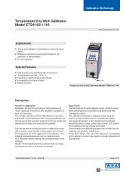
5. SPECIFICATIONS<br />
<strong>Series</strong> <strong>6100</strong> Specifications . . . . . . . . . . . . . . . . . . . . . 5-1<br />
Figures<br />
1.2 – DPT Block Diagram . . . . . . . . . . . . . . . . . . . . . 1-2<br />
2.1 – Mounting . . . . . . . . . . . . . . . . . . . . . . . . . . . 2-1<br />
2.2 – RS-232 Hookup . . . . . . . . . . . . . . . . . . . . . . . . 2-2<br />
2.3 – RS-485 Cabling . . . . . . . . . . . . . . . . . . . . . . . . 2-3<br />
4.1 – Calibration Setup . . . . . . . . . . . . . . . . . . . . . . . 4-3<br />
Tables<br />
1.1 – <strong>Series</strong> <strong>6100</strong> DPT Models . . . . . . . . . . . . . . . . . . . 1-2<br />
3.1 – Serial Port Settings . . . . . . . . . . . . . . . . . . . . . . 3-2<br />
3.2 – Command Conventions . . . . . . . . . . . . . . . . . . . . 3-3<br />
3.3 – Command Set . . . . . . . . . . . . . . . . . . . . . 3-4 - 3-5<br />
3.4 – Units Codes and Conversions . . . . . . . . . . . . . . . . . 3-6<br />
vi February, 2002 MENSOR® CORP.
SERIES <strong>6100</strong> DPT INTRODUCTION<br />
INTRODUCTION<br />
DID YOU GET EVERYTHING?<br />
In addition to this manual and password envelope (attached to rear cover) you should have:<br />
• One <strong>Series</strong> <strong>6100</strong> Digital Pressure Transducer (DPT) with a serial number matching the<br />
one shown on the front cover of this manual;<br />
• Two data disks with a utility program to read and calibrate a <strong>Series</strong> <strong>6100</strong> DPT;<br />
• Any accessories ordered;<br />
• An envelope containing a Calibration Certificate and a Warranty Certificate.<br />
INITIAL INSPECTION<br />
In addition to functional testing, each unit is inspected for appearance prior to leaving the<br />
factory. Upon receipt, please examine the transducer for shipping damage. Report any<br />
apparent damage to the carrier immediately.<br />
GENERAL DESCRIPTION<br />
The <strong>Series</strong> <strong>6100</strong> Digital Pressure Transducer (DPT) is a self-contained pressure sensing<br />
device that provides high accuracy pressure measurements. This transducer incorporates<br />
a low hysteresis silicon sensor with electronically compensated pressure linearity over the<br />
specified temperature range. Communication with the DPT is over a serial bus, either<br />
RS-232 or RS-485.<br />
Turndowns<br />
The transducer has the capability to include two distinct ranges (turndowns) using a single<br />
sensor. The primary turndown is always the higher range of the transducer. The second<br />
turndown has exactly the same performance specifications, but at some lower full scale<br />
range. At powerup the primary turndown is active by default.<br />
Power Supply<br />
The required 6 to 20 VDC power enters the DPT via J1. All of the transducer electronics<br />
and communications share a common ground.<br />
Sensor<br />
The pressure sensor is a micromachined silicon strain gauge. The sensor is secured to the<br />
transducer case.<br />
Circuitry<br />
All of the circuitry for the DPT is included on a single PC board. The combined pressure<br />
and temperature sensor signals are routed to the signal conditioning electronics.<br />
MENSOR® CORP. February, 2002 1-1
INTRODUCTION SERIES <strong>6100</strong> DPT<br />
Serial In/Out Communications<br />
The serial bus is set to either RS-232 or RS-485 at the factory. The bus is a two way<br />
communication path used to receive commands and return measured pressure values and<br />
other transducer information to the user. This port is also used to transmit calibration<br />
adjustments and other user functions to the DPT. Pressure units for each transducer are<br />
specified by the customer. Wiring requirements for the serial port are provided in the<br />
Installation section and a list of valid commands and responses (table 3.3) is provided in<br />
the Operation section.<br />
Pressure<br />
Port<br />
Sensor<br />
SERIES <strong>6100</strong> DPT MODELS<br />
TRANSDUCER CASE (Gauge Sensor Reference Chamber)<br />
EEPROM<br />
A/D<br />
Converters<br />
Micro-<br />
Controller<br />
MULTI-FUNCTION PCB<br />
+5 / +12V<br />
Converter<br />
RS-232/485<br />
Converter<br />
Figure 1.1 - DPT Block Diagram<br />
The <strong>Series</strong> <strong>6100</strong> Transducer can be purchased in a variey of configurations. The following<br />
table describes possible configurations based on the model number.<br />
Table 1.1 - <strong>Series</strong> <strong>6100</strong> DPT Models<br />
Model Description<br />
6110 1 cal, RS-232<br />
6120 1 cal, RS-485<br />
6130 2 cals, RS-232<br />
6140 2 cals, RS-485<br />
61X1 1 VDC<br />
61X3 5 VDC<br />
61X4 4-20 mA<br />
61X5 10 VDC<br />
+6 to 20 VDC<br />
Gnd (Common)<br />
Reference<br />
Port<br />
1-2 February, 2002 MENSOR® CORP.<br />
6<br />
7<br />
8<br />
9<br />
J1<br />
1<br />
2<br />
3<br />
4<br />
5
SERIES <strong>6100</strong> DPT INSTALLATION<br />
INSTALLATION<br />
CONFIGURATION<br />
A typical system will consist of an IBM-PC compatible computer with installed driver<br />
software, one or more DPTs, a DC voltage power supply, and the interconnecting cables.<br />
The driver software can be any program configured to operate the appropriate serial<br />
interface. Up to 31 DPTs can be connected in parallel using RS-485. Figure 2.3 illustrates<br />
two alternate RS-485 wiring arrangements, including multiple DPT operation.<br />
MOUNTING<br />
The DPT has two 6-32 threaded holes in the back of the top, two on the back of the bottom,<br />
and four on the bottom for mounting. The DPT can be set up in any orientation since the<br />
pressure sensor is relatively insensitive to tilt and vibration. However, excessive motor or<br />
machinery vibration of the mounting surface should be avoided to further ensure stability<br />
and accuracy. For the greatest accuracy on transducers with a full scale range of less than<br />
15 psi, set DPT zero while it is oriented in its operational position.<br />
PRESSURE CONNECTIONS<br />
The pressure to be measured is applied to the left 7/16-20 SAE female threaded port labeled<br />
P on top of the DPT. The right 7/16-20 SAE female port is used as the reference port for<br />
gauge pressure and is labeled R. The reference port is normally left open to atmosphere,<br />
but it can be connected to another source for a reference pressure. The reference port is<br />
plugged at the factory for absolute pressure transducers.<br />
ELECTRICAL CONNECTIONS<br />
Figure 2.1 - Mounting<br />
Connector J1 Wiring<br />
Power and signals are applied to J1, a 9-pin D-sub male connector. A positive power supply<br />
voltage is supplied to pin 6, and ground (power and signal common) is connected to pin 5.<br />
MENSOR® CORP. February, 2002 2-1
INSTALLATION SERIES <strong>6100</strong> DPT<br />
The DPT is protected against power input reversal. Wiring between the host and J1 is<br />
described by figures 2.2 and 2.3.<br />
RS-232 Operation<br />
For RS-232 serial port operation connect the DPT to the host computer per figure 2.2.<br />
Notice that the host TRANSMIT line is connected to the DPT RECEIVE line (TX to RX), and<br />
vice versa. One limitation of the RS-232 bus is that a host can support only one instrument.<br />
See “RS-485 Operation” for multiple DPT operation.<br />
Host<br />
DB-9<br />
+6 to 20 VDC<br />
2 RX<br />
2<br />
3 TX<br />
SHLD<br />
3<br />
5 GND<br />
5<br />
NOTE: Connectors are female, shown from the wired end.<br />
Figure 2.2 - RS-232 Hookup<br />
DPT-J1<br />
RS-485 Operation<br />
For RS-485 serial operation, connect the host computer to the DPT per either the two-wire<br />
or the four-wire diagram shown in figure 2.3. Notice that the host TRANSMIT lines are<br />
connected to the DPT RECEIVE lines, TA to RA, TB to RB, and so on.<br />
If only one RS-485 DPT will be connected to the system, disregard the wiring to “DPT #1"<br />
and ”DPT #2" in the illustrations. Instead, wire the computer directly to the “DPT #31” by<br />
either the two-wire, or the four-wire method.<br />
To connect multiple RS-485 DPTs to a single host, use the full multi-drop wiring shown in<br />
either part of figure 2.3. In either configuration, one computer can communicate with up<br />
to 31 DPTs without a repeater, but each DPT in the system must have a unique address.<br />
The signal is simultaneously distributed to each transducer connected to the parallel path.<br />
Each DPT responds only to commands or queries directed to its own address. Removal of<br />
one or more DPTs from the line has no effect on the remaining devices.<br />
Terminating resistor examples are shown and should be determined by the end user when<br />
cabling extremes are required. Resistor values are selected to match the characteristic<br />
impedance of the transmission line, typically 100 to 120 ohms.<br />
2-2 February, 2002 MENSOR® CORP.<br />
6
SERIES <strong>6100</strong> DPT INSTALLATION<br />
Host DB-9<br />
TA<br />
TB<br />
RA<br />
RB<br />
GND<br />
Host DB-9<br />
TA 3<br />
TB<br />
RA<br />
RB<br />
GND<br />
3<br />
2<br />
1<br />
9<br />
5<br />
2<br />
1<br />
9<br />
5<br />
Rt<br />
Rt<br />
Rt<br />
+6 to 20 VDC<br />
+6 to 20 VDC<br />
4,000 ft max<br />
5 3 9 1 2 6 J1 -<br />
DPT #31<br />
5 3 9 1 2 6<br />
DPT<br />
Case<br />
5 3 2 1 9 6 J1 -<br />
DPT #31<br />
5 3 2 1 9 6<br />
DPT<br />
Case<br />
DPT<br />
Case<br />
DPT<br />
Case<br />
NOTES: 1. All resistors are 1/2 watt, approximately 100 ohm.<br />
2. Rt = Terminating resistors; two farthest ends only.<br />
4,000 ft max<br />
Figure 2.3 - RS-485 Cabling<br />
J1 -<br />
DPT #2<br />
+6 to 20 VDC<br />
J1 -<br />
DPT #2<br />
+6 to 20 VDC<br />
Rt<br />
Rt<br />
Rt<br />
Two-Wire<br />
Hookup<br />
J1 - DPT #1<br />
DPT<br />
Case<br />
6<br />
3<br />
1<br />
9<br />
5<br />
RA<br />
RB<br />
TA<br />
TB<br />
GND<br />
Four-Wire<br />
Hookup<br />
DPT<br />
Case<br />
6<br />
3<br />
1<br />
9<br />
5<br />
2<br />
J1 - DPT #1<br />
2<br />
RA<br />
RB<br />
TA<br />
TB<br />
GND<br />
+6 to 20 VDC<br />
+6 to 20 VDC<br />
MENSOR® CORP. February, 2002 2-3
INSTALLATION SERIES <strong>6100</strong> DPT<br />
User's Notes:<br />
2-4 February, 2002 MENSOR® CORP.
SERIES <strong>6100</strong> DPT OPERATION<br />
OPERATION<br />
GENERAL<br />
Use caution to avoid excessive overpressure to the sensor. Externally mounted relief valves<br />
to provide overpressure protection are available from Mensor as optional devices, and are<br />
highly recommended for very low pressure transducers.<br />
User programmable exponential filtering is applied to pressure readings in order to<br />
minimize at or near static pressure noise. The filter value can range from 0 (filter OFF) to<br />
99 (maximum filtering). For any positive filter value, the filter is disabled when the pressure<br />
change between consecutive readings is greater than 0.01% full scale. However, each<br />
pressure change of 0.01% FS, or less, between consecutive readings will apply the exponential<br />
filter to the output pressure value to smooth out the readings.<br />
The user can reset the zero and span values via the serial port in order to calibrate the<br />
instrument, or the user can change any of several other operating values. The user can also<br />
query the device for its current pressure reading, or to find the current settings for other<br />
parameters.<br />
The serial port is set at the factory for either RS-232 or for RS-485 serial operation according<br />
to the customer’s instructions. This section of the manual provides information on the serial<br />
port configuration, explains the command conventions used in this manual, and lists the<br />
common commands and queries which are recognized by the DPT.<br />
Multiple Turndown Devices<br />
The availability of two different turndown ranges in one device has many obvious benefits,<br />
but certain issues should be noted for application of devices with multiple ranges. An<br />
important factor to remember is the two ranges are completely discrete except for the<br />
address. Consequently, certain parameters can be set to different values between the two<br />
turndown ranges.<br />
Filter Effects of Multiple Turndowns: An area of concern when using devices with<br />
multiple turndowns is the effect of the exponential filter on the reading output. In the case<br />
that a user is emulating an auto-ranging scheme by quickly switching between turndown<br />
ranges of one device, the exponential filter can skew the reading output of the device<br />
immediately after a switch is made. The reason for this skewing is the persistence of previous<br />
pressure samples in the reading buffer and their use in the filtering scheme.<br />
The filter equation for the transducer is as follows where FL is set to 90: If the change in<br />
pressure reading is less than 0.01% of the last pressure reading sampled at a 20 mS rate,<br />
then the pressure reading = (Last Filtered Pressure * 90%) + (Current Sampled Pressure<br />
* 10%). Otherwise the pressure reading is equal to the current sampled pressure. The<br />
default setting is 90% filtering.<br />
MENSOR® CORP. February, 2002 3-1
OPERATION SERIES <strong>6100</strong> DPT<br />
Consequently, the readings from the previous active turndown in the reading buffer of the<br />
device affect the current reading. The amount the new reading is affected is a function of<br />
the size of the filter percentage setting of the active turndown. The largest offset that will be<br />
reported by the newly active turndown is 0.01% FS of the current range. In applications<br />
where readings must not slew in immediately after a turndown switch is made, it is advisable<br />
to set the filter to zero or to program a delay before the new turndown is read.<br />
Both turndowns share the same address. However, if you change the address of one<br />
turndown without saving it, the address will revert to the previously saved address when<br />
you switch turndowns.<br />
Serial Port Configuration<br />
Unless otherwise requested by the customer, the DPT serial ports are set at the factory to<br />
the default values shown in table 3.1.<br />
Table 3.1 - Serial Port Settings<br />
Item Value<br />
Type RS-232<br />
Address 1<br />
Baud 9600<br />
Data Bits 8<br />
Parity None<br />
Stop Bits 1<br />
DPT Address<br />
Each DPT is assigned address “1" at the factory. In a multiple DPT system each transducer<br />
must have a unique address. Valid addresses are 0 through 9 and A through Z (upper and<br />
lower case are interpreted the same). The procedure for changing an address is explained<br />
in the text under “Commands”.<br />
Wildcard Address Operator (*)<br />
In addition to the 36 unique addresses available, an asterisk (*) functions as a wildcard<br />
address operator. However, this wildcard must not be used in queries if more than one<br />
transducer is connected to a host. The wildcard can be used to address multiple devices<br />
with commands.<br />
One use for the wildcard address could be when a DPT is pulled out of a multi-drop setup<br />
and sent to a calibration facility for recertification. The calibration technician can communicate<br />
with the device using the wildcard address without learning or changing its assigned<br />
address.<br />
3-2 February, 2002 MENSOR® CORP.
SERIES <strong>6100</strong> DPT OPERATION<br />
Communication Syntax and Command Conventions<br />
All commands and responses are in ASCII characters; lower and upper case are interpreted<br />
the same. Every command or query begins with the pound symbol (#). The question mark<br />
(?) and decimal point (.) characters are significant to the DPT. All other punctuation<br />
characters are ignored. Some commands require a password string. A carriage return<br />
() or linefeed () should terminate each command or query.<br />
Password Protection: Certain commands require a password to be sent before a setting<br />
is changed. The password is only good for one command, so the password string must be<br />
sent immediately before any password protected command string. The form of the password<br />
string is described in table 3.3. However, for calibration protection, the actual password<br />
has been replaced with PW in the command string example. See the envelope at the end of<br />
this manual for the actual password string to be used in place of PW.<br />
When using 2-wire RS-485 configuration, care should be taken to not append the data string<br />
with both a carriage return and a linefeed . Use one terminator or the other, only.<br />
When receiving data from the DPT, both a carriage return and a linefeed will be<br />
sent to terminate the data string. The linefeed will always be the last character sent<br />
by the DPT.<br />
Response String Format: The DPT will return an R to indicate that it has received a<br />
command or password rather than a query. When programming communication with the<br />
DPT, it is advisable to look for the R response before sending additional commands or<br />
queries.<br />
The full command word is shown in table 3.3 in all capital letters. Other conventions used<br />
to describe commands are shown in table 3.2.<br />
Table 3.2 - Command Conventions<br />
Convention Description<br />
A Address (single character 0 through 9 or A through Z; case insensitive)<br />
* Wildcard address operator<br />
? Query operator<br />
Space ( )<br />
PW Password; insert password in place of PW (see password envelope; case insensitive)<br />
n One character placeholder for digit or decimal point<br />
n...n Variable length field<br />
R Ready response<br />
Carriage return<br />
Linefeed<br />
MENSOR® CORP. February, 2002 3-3
OPERATION SERIES <strong>6100</strong> DPT<br />
Commands and Queries<br />
NOTE: Each command that changes a parameter is volatile until the SAVE command<br />
is issued.<br />
Table 3.3 - Command Set<br />
Password<br />
Protect<br />
Command/<br />
Query Command String Return String Description<br />
No ? #A? Annnnnnnnnn Basic query to return<br />
pressure readings.<br />
No A #An R Sets address of sensor<br />
to 0-9 or A-Z.<br />
No B? #AB? ABn Returns the turndown,<br />
number.<br />
No DC? #ADC? ADCnnnnnn<br />
<br />
Returns the date of<br />
calibration where<br />
nnnnnn is mmddyy.<br />
Yes DC #ADCnnnnnn R Loads the date of<br />
calibration where<br />
No FL? #AFL? AFLnn<br />
nnnnnn is mmddyy.<br />
Returns the filter – it is<br />
the percentage of old<br />
reading added to new<br />
reading: 0 to 99.<br />
Yes FL #AFLnn R Sets the filter<br />
percentage.<br />
No FS? #AFS? AFSnnnnn<br />
<br />
No ID? #AID? AIDnnMENSOR,<br />
nnnn61nn,nnnnnnn<br />
n,Vn.nn<br />
Returns the % FS accuracy.<br />
Returns transducer id.<br />
N/A PW #APW R Disables password<br />
protection for the<br />
following single command.<br />
See page 3-3 for<br />
information on using<br />
the password.<br />
Continued on next page . . .<br />
3-4 February, 2002 MENSOR® CORP.
SERIES <strong>6100</strong> DPT OPERATION<br />
Table 3.3 continued . . .<br />
Password<br />
Protect<br />
Command/<br />
Query Command String Return String Description<br />
No R-? #AR-? AR-n...n Returns minimum<br />
range value.<br />
No R+? #AR+? AR+n...n Returns maximum<br />
range value.<br />
No SAVE #ASAVE R Saves all data to<br />
EEPROM for the<br />
No SC? #ASC? ASCn...n<br />
current turndown.<br />
Returns a span correction<br />
multiplier.<br />
Yes SC #ASCn...n R Loads a span correction<br />
multiplier.<br />
No SW #ASWn R Switches between<br />
No T? #AT? ATC<br />
‘n’=1 for primary cal or<br />
‘n’=2 for secondary cal.<br />
Returns cal type.<br />
No U? #AU? An Returns pressure units<br />
code. See Table 3.4.<br />
No ZC? #AZC? AZCn...n Returns zero<br />
correction value in<br />
current units.<br />
Yes ZC #AZCn...n R Sets zero correction<br />
value in current units.<br />
MENSOR® CORP. February, 2002 3-5
OPERATION SERIES <strong>6100</strong> DPT<br />
Units Codes and Conversions<br />
Table 3.4 - Units Codes and Conversions<br />
Code Units PSI Conversion Factor<br />
1 psi 1<br />
2 inHg@0°C 2.036020<br />
3 inHg@60°F 2.041772<br />
4 inH2O@4°C 27.68067<br />
5 inH2O@20°C 27.72977<br />
6 inH2O@60°F 27.70759<br />
7 ftH2O@4°C 2.306726<br />
8 ftH2O@20°C 2.310814<br />
9 ftH2O@60°F 2.308966<br />
10 mtorr (@0°C) 51715.08<br />
11 inSW @ 0°C 3.5% sal 26.92334<br />
12 ftSW @ 0°C 3.5% sal 2.243611<br />
13 atm 0.06804596<br />
14 Bars 0.06894757<br />
15 mBars 68.94757<br />
16 mmH2O@4°C 703.0890<br />
17 cmH2O@4°C 70.30890<br />
18 mH2O@4°C 0.7030890<br />
19 mmHg@0°C 51.71508<br />
20 cmHg@0°C 5.171508<br />
21 Torr 51.71508<br />
22 Kpa 6.894757<br />
23 Pa 6894.757<br />
24 Dynes/cm 2<br />
68947.57<br />
25 g/cm 2<br />
70.30697<br />
26 kg/cm 2<br />
0.07030697<br />
27 mSW @ 0°C 3.5% sal 0.6838528<br />
28 oz/in 2<br />
16<br />
29 psf 144<br />
30 tsf 0.072<br />
31 % Full Scale<br />
32 microns Hg @ 0 °C 51715.08<br />
33 tsi 0.0005<br />
35 HPa 68.94757<br />
36 MPa 0.006894757<br />
3-6 February, 2002 MENSOR® CORP.
SERIES <strong>6100</strong> DPT CALIBRATION<br />
CALIBRATION<br />
The DPT automatically adjusts the pressure readings for the effects of temperature and<br />
non-linearity within the calibrated temperature range of 15-45°C. Thus, a calibrated DPT<br />
operated within its temperature band, and with proper zero and span settings, will provide<br />
accurate pressure measurements.<br />
The transducer should have the span verified periodically to insure its stability. Initially,<br />
the recommended period between calibrations is six months. This period may be extended<br />
as confidence is gained in the stability of the DPT.<br />
ENVIRONMENT<br />
Whenever possible, calibrate the DPT at the same ambient temperature as its normal<br />
operating environment. The temperature should be stable, and within the specified calibration<br />
range. In addition, for maximum accuracy, see that the DPT is at rest on a stable<br />
platform which is free of vibration and shock, and oriented similar to its final installation<br />
attitude. At the factory the DPT is calibrated vertically with the pressure port at the top.<br />
EQUIPMENT<br />
The following equipment is needed to calibrate a gauge transducer (see figure 4.1):<br />
1. A host computer with a serial port to match the DPT (RS-232 or RS-485), software to<br />
run the <strong>Series</strong> <strong>6100</strong> transducer, and an appropriate cable.<br />
2. A pressure source with a line-pressure regulator to cover the full scale pressure range<br />
of the DPT.<br />
3. A hand operated variable-volume pressure vernier (volume controller).<br />
4, A metering valve and two isolating valves for Vent and Supply Pressure.<br />
5. A pressure calibration standard.<br />
6. Tubing and fittings adequate for the pressure range.<br />
Additional equipment required to calibrate sub-atmospheric transducers (absolute. vacuum<br />
or bi-directional pressure types) is illustrated in figure 4.1. These items are:<br />
7. A vacuum pump capable of pumping down to 300 millitorr.<br />
8. A vacuum standard to measure pressures down to 300 millitorr.<br />
9. One additional valve to isolate the vacuum line.<br />
MENSOR® CORP. February, 2002 4-1
CALIBRATION SERIES <strong>6100</strong> DPT<br />
PRESSURE STANDARD<br />
Mensor recommends the use of appropriately accurate primary pressure standards when<br />
calibrating this instrument. Such standards should be sufficient so that when the techniques<br />
of the ISO Guide to the Expression of Uncertainty in Measurement (GUM) are<br />
applied, the instrument meets its accuracy statements as required by ANSI/NCSL Z540, or<br />
other applicable standards. The same requirement applies to the vacuum gauge used to<br />
set the zero offset on absolute calibrations. The recommended absolute pressure level for<br />
setting the zero offset is ≥300 mTorr.<br />
CALIBRATION MEDIUM<br />
The recommended calibration medium for sensors up to 2500 psi is dry nitrogen. Hydraulic<br />
media (water or oil for example) are recommended for ranges above 2500 psi. Hydraulic<br />
media can be used with lower ranges, however, special techniques must be used in filling<br />
the connection lines and transducer.<br />
CALIBRATION PROCESS<br />
Please notice that the commands listed in this section are shown in the same style as those<br />
in the Operation section. These are the bare commands seen by the DPT, stripped of all<br />
programming idioms. Depending on the specific language used to generate them, these<br />
commands may have to be preceded by or enclosed in various symbols for transmission.<br />
For this procedure it is assumed that a single DPT is connected to the host computer, and<br />
that its assigned address is unknown.<br />
The model, serial number, and software version number of the DPT being calibrated can<br />
be obtained by sending: #*ID?.<br />
CORRECTION VALUE QUERY<br />
The stored correction for zero offset or the span correction factor can be retrieved over the<br />
bus. The returned values have six significant digits plus a decimal point and a sign. To see<br />
the stored values send either:<br />
#*ZC? or #*SC?<br />
These commands may be useful in determining the actual changes in zero and span over<br />
time. Unauthorized alterations of the values can be detected by comparison with previously<br />
recorded correction values.<br />
NOTE: Each command issued to either calibration parameter must be followed by the<br />
SAVE command to make it permanent. Otherwise, the changes will be lost the next time<br />
the DPT loses power.<br />
4-2 February, 2002 MENSOR® CORP.
SERIES <strong>6100</strong> DPT CALIBRATION<br />
Pressure<br />
Supply<br />
Pressure<br />
Pressure<br />
Standard<br />
Reference<br />
Pressure<br />
Supply<br />
Pressure<br />
Pressure<br />
Standard<br />
Line<br />
Regulator<br />
Volume<br />
Controller<br />
Line<br />
Regulator<br />
Volume<br />
Controller<br />
Shut-off<br />
Valves<br />
Shut-off<br />
Valves<br />
Metering<br />
Valve<br />
Metering<br />
Valve<br />
Vent<br />
Diaphragm Type<br />
Vacuum Gauge VAC<br />
Pressure<br />
Reference<br />
Shut-off<br />
Valve<br />
Pressure<br />
Setup for Gauge<br />
Pressure Calibration<br />
Shut-off<br />
Valve<br />
Vent<br />
Atmosphere<br />
Setup for Absolute<br />
Pressure Calibration<br />
Vent<br />
Vacuum<br />
NOTE: Disconnect when the vacuum<br />
gauge range is exceeded.<br />
Figure 4.1 - Calibration Setup<br />
Computer<br />
Serial<br />
Cable<br />
Gauge Pressure<br />
<strong>Series</strong> <strong>6100</strong><br />
P<br />
R<br />
Computer<br />
Absolute Pressure<br />
<strong>Series</strong> <strong>6100</strong><br />
MENSOR® CORP. February, 2002 4-3<br />
Serial<br />
Cable
CALIBRATION SERIES <strong>6100</strong> DPT<br />
ZERO ADJUSTMENT<br />
To adjust zero, first determine the correct zero offset, then send the password, and then<br />
send the new zero value. Applying the correct zero pressure and finding the resulting zero<br />
offset is different for an absolute transducer than it is for a gauge type unit. Once the zero<br />
offset is known, the procedure for sending the zero correction value (which sets the output<br />
to zero) is the same for either type of transducer. When the zero offset is correct, issue a<br />
SAVE command to preserve it in non-volatile memory.<br />
Gauge/Differential Zero Offset<br />
Substitute the required password in place of “PW” in the following examples:<br />
1. Determine the current zero offset and make a note of the returned reading.<br />
Next send: #*ZC?<br />
Record the date and this reading to track zero changes between calibrations.<br />
2. Vent the PRESSURE and REFERENCE ports to atmosphere.<br />
The true pressure is now 0 (zero).<br />
Send: #*PW<br />
Next send: #*ZC0<br />
This will clear the current zero offset from RAM.<br />
3. While vented, determine the current zero pressure reading of the DPT.<br />
Send: #*?<br />
Make a note of the zero value returned by the DPT.<br />
4. Subtract the current zero reading from true zero.<br />
The difference is the new zero offset.<br />
Example: For a 0-30 psi unit with both ports vented:<br />
True Pressure = 0 (vented)<br />
Current Pressure reading (from step 4) = +0.0023 psi<br />
True Pressure – Current Pressure = New Offset<br />
0.0000 (–) +0.0023 = –0.0023 psi offset<br />
5. Enter the new offset into memory.<br />
Send: #*PW<br />
Next send the zero offset: #*ZC–.0023<br />
The new offset of –0.0023 will now be added to all pressure readings of the DPT.<br />
Send: #*SAVE to store the new value in non-volatile memory.<br />
6. To check the zero correction:<br />
Send: #*?<br />
The reading returned should be 0.0000 psi with both ports vented.<br />
4-4 February, 2002 MENSOR® CORP.
SERIES <strong>6100</strong> DPT CALIBRATION<br />
Absolute Zero Offset<br />
Substitute the required password in place of “PW” in the following examples:<br />
1. Find the current zero offset and make a note of the returned value.<br />
Send: #*ZC? and record the reading.<br />
2. Use the setup for absolute pressure shown in figure 4.1. Evacuate and hold the sensor<br />
at approximately 300 to 400 millitorr. Allow the system to stabilize at that pressure<br />
for two to five minutes. Take the vacuum reading and convert it to an equivalent psi<br />
value. This reading becomes the “true pressure”.<br />
3. Clear the current zero offset from RAM.<br />
Send: #*PW<br />
Next send: #*ZC 0<br />
4. Determine the current pressure reading.<br />
Send: #*? and make a note of this reading.<br />
5. Subtract the current pressure reading from the true pressure (vacuum) reading.<br />
The difference is the zero offset now required.<br />
Example: For a 0-15 psia unit with 300 millitorr vacuum applied, using psi units:<br />
300 millitorr = 0.0058 psia (True Pressure)<br />
Current Pressure reading (from step 4) = –0.0011 psia<br />
True Pressure – Current Pressure = New Offset<br />
0.0058 (–) –0.0011 = +0.0069 psi offset<br />
6. Enter the new offset into memory.<br />
Send: #*PW<br />
Then send: #*ZC.0069<br />
The new offset of 0.0069 will now be added to all pressure readings.<br />
Send: #*SAVE to store the new value in non-volatile memory.<br />
7. To check the zero correction:<br />
Send: #*?<br />
For 300 mtorr the pressure reading returned should be 0.0058 psia.<br />
MENSOR® CORP. February, 2002 4-5
CALIBRATION SERIES <strong>6100</strong> DPT<br />
SPAN ADJUSTMENT<br />
The span adjustment procedure is the same for gauge and absolute units. Always make<br />
zero corrections before changing the span factor. A scale factor within the range of 0.9 to<br />
1.1 is used as a multiplier to correct for span shifts.<br />
1. Determine the current span scale factor and record the reading.<br />
Send: #*SC?<br />
This reading can be used at some later date to detect a span change between<br />
calibrations.<br />
2. To clear the current scale factor:<br />
Send: #*PW<br />
Next send: #*SC1<br />
3. Apply a known true pressure equal to the span of the DPT.<br />
To determine the DPT pressure reading:<br />
Send: #*? and make a note of this reading.<br />
4. Divide the known true pressure by the DPT pressure reading.<br />
The result is the required new span scale factor.<br />
Example: For a 150 psi unit:<br />
True Pressure = 150.003 psi<br />
DPT Pressure reading (from step 3) = 149.984 psi<br />
True Pressure/DPT Pressure = New Span Scale Factor<br />
150.003/149.984 = 1.000127<br />
5. To enter the new span scale factor:<br />
Send: #*PW<br />
Then send: #*SC1.000127<br />
Send: #*SAVE to store the new value in non-volatile memory.<br />
All future pressure readings returned by this DPT will be multiplied by a scale factor<br />
of 1.000127 before they are transmitted over the bus.<br />
6. To check the span reading:<br />
Send: #*?<br />
The returned pressure value should be 150.003 psi, if the pressure has not changed.<br />
4-6 February, 2002 MENSOR® CORP.
Accuracy 0.010% FS<br />
Precision 0.003% FS<br />
Calibration<br />
Stability<br />
after warm-up<br />
Better than 0.01% FS for 180 days. Zero<br />
and Span may be reset via the serial interface<br />
without affecting Linearity.<br />
Calibration<br />
Cal Interval: 180 Days<br />
Uncertainties: 0.010% FS<br />
Adjustments: Zero and Span via the serial interface<br />
Standard Ranges - Standard<br />
psia: 0-5 to 0-6,000 max<br />
psig: 0-0.36 to 0-6,000 max<br />
Pressure Range - Bidirectional, Vacuum<br />
psig: -0.36 to +0.36 min., -atm to 6,000 max<br />
Pressure Units psi, inHg @ 0°C and 60°F, inH2O @4°C,<br />
20°C and 60°F, ftH2O @4°C, 20°C and<br />
60°F, mTorr, inSW @ 0°C, ftSW @ 0°C,<br />
ATM, bars, mbars, mmH2O @4°C, cm<br />
H2O@4°C, MH2O@4°C, mmHg @ 0°C,<br />
cmHg @ 0°C, Torr, hPa, mPa, kPa, Pa,<br />
D/cmsq, g/cmsq, kg/cmsq, mSW @ 0°C,<br />
OSI, PSF, TSF, TSI, µHg @ 0°C, %fs.<br />
All seawater units are @ 3.5% salinity.<br />
Resolution From 2-10 ppm, depending on measurement<br />
units and range.<br />
Overpressure<br />
Limit<br />
Storage 0to70°C<br />
DIMENSIONS<br />
150% FS or greater, depending on range<br />
Accuracy includes the following uncertainties in the pressure reading:<br />
repeatability, pressure hysteresis, creep, linearity, and temperature<br />
effects over the compensated range.<br />
Precision is the closeness of agreement between independent test<br />
results obtained under stipulated conditions.<br />
Per ANSI/NCSL Z540-2-1997 (U.S. Guide to the Expression of Uncertainty<br />
in Measurement) “the term precision should not be used for<br />
accuracy”.<br />
SERIES <strong>6100</strong> SPECIFICATIONS<br />
SAN MARCOS, TX 78666 (512) 396-4200<br />
SERIES <strong>6100</strong> DIGITAL<br />
PRESSURE TRANSDUCER<br />
SERIAL NUMBER:<br />
TURNDOWN 1<br />
PRESSURE RANGE:<br />
PRESSURE TYPE:<br />
ACCURACY:<br />
Warm-up 10 minutes to rated accuracy<br />
Reading Rate 50 per second<br />
Response Time =20ms<br />
Orientation Effects