CPC 3000 High Speed Pressure Controller - CALIBRATION ONLINE
CPC 3000 High Speed Pressure Controller - CALIBRATION ONLINE
CPC 3000 High Speed Pressure Controller - CALIBRATION ONLINE

You also want an ePaper? Increase the reach of your titles
YUMPU automatically turns print PDFs into web optimized ePapers that Google loves.
<strong>High</strong> <strong>Speed</strong> <strong>Pressure</strong> <strong>Controller</strong><br />
<strong>CPC</strong> <strong>3000</strong><br />
Mensor receives Rosemount Strategic<br />
Supplier Award 14 consecutive<br />
years<br />
Operating Instructions<br />
<strong>High</strong> <strong>Speed</strong> <strong>Pressure</strong> <strong>Controller</strong> <strong>CPC</strong> <strong>3000</strong> Pt#: 0018043001 Version 1.1<br />
ACCREDITED
<strong>High</strong> <strong>Speed</strong> <strong>Pressure</strong> <strong>Controller</strong><br />
<strong>CPC</strong> <strong>3000</strong><br />
!<br />
Warning<br />
!<br />
Caution<br />
i<br />
Notice<br />
This Warning symbol indicates that danger of injury for persons and the<br />
environment and/or considerable material damage (mortal danger, danger of<br />
injury) will occur if the respective safety precautions are not taken.<br />
This Caution symbol indicates danger for the system and material if the<br />
respective safety precautions are not taken.<br />
This Notice symbol does not indicate safety notices but information for a<br />
better understanding of the facts.<br />
Mensor / WIKA Operating Instruction <strong>High</strong> <strong>Speed</strong> <strong>Pressure</strong> <strong>Controller</strong>∙ Version 1.1
<strong>High</strong> <strong>Speed</strong> <strong>Pressure</strong> <strong>Controller</strong><br />
<strong>CPC</strong> <strong>3000</strong><br />
Table of Contents<br />
1. General Information 5<br />
1.1 Warranty 5<br />
1.2 Important Notice 5<br />
1.3 FCC Radio Frequency Emission notice 6<br />
1.4 Trademarks and Copyrights 6<br />
1.5 Software License Agreement 6<br />
1.6 Accreditations 6<br />
1.7 Packaging for Shipment 7<br />
2. Safety notices 7<br />
2.1 User Responsibilities 7<br />
2.2 General safety notices 8<br />
2.3 Warnings and caution notices 8<br />
3. Product description 11<br />
3.1 Proper use 11<br />
3.2 Features 1<br />
3.3 Turning on the <strong>CPC</strong> <strong>3000</strong> 1<br />
3.4 Front panel 1<br />
3.5 Main Menu 14<br />
3.5.1 Keys, Tabs, Check Boxes, Labels/Graphics 14<br />
3.6 Front Panel Variations and Navigation 15<br />
3.6.1 Operating Mode selection 15<br />
3.7 Main menu setpoint entry options 17<br />
4. Specifications 18<br />
5. Installation 19<br />
5.1 Introduction 19<br />
5.2 Unpacking the system 19<br />
5.3 Dimensions in Inches 19<br />
5.4 Installation 0<br />
5.5 Rear panel 1<br />
5.6 <strong>Pressure</strong> connections 1<br />
5.7 Function of pressure connections<br />
5.8 Electrical connections<br />
5.8.1 Connecting the power supply and turning on the instrument<br />
5.8.2 Connecting the Communications interfaces<br />
6. Starting operation 25<br />
Mensor / WIKA Operating Instruction <strong>High</strong> <strong>Speed</strong> <strong>Pressure</strong> <strong>Controller</strong>∙ Version 1.1
<strong>High</strong> <strong>Speed</strong> <strong>Pressure</strong> <strong>Controller</strong><br />
<strong>CPC</strong> <strong>3000</strong><br />
7. Local Operation 27<br />
7.1 Setting the operating language 7<br />
7.2 Display configuration 7<br />
7.3 Setpoint Entry 9<br />
7.4 Operating modes 0<br />
7.5 Data Entry 1<br />
7.6 "<strong>Pressure</strong> unit", "pressure mode" and "emulation mode" 1<br />
7.7 Bar Chart<br />
7.8 Setup Menus<br />
7.8.1 Setup Display<br />
7.8.2 Setup Control 4<br />
7.8.3 Setup Remote 5<br />
7.8.4 Setup Info 6<br />
7.8.5 Setup Service 7<br />
8. Remote Operation 41<br />
8.1 Remote Setup 4<br />
8.2 Remote Setup - Ethernet 4<br />
8.3 Remote Setup - USB 4<br />
8.4 Remote Setup -I EEE-488 4<br />
8.5 Remote Command Set 44<br />
8.5.1 Mensor Command Set 44<br />
8.5.2 PCS 400 Commands Emulated 5<br />
8.5.3 PCS 200 Commands Emulated 55<br />
8.5.4 DPI 510 Commands Emulated 56<br />
8.5.5 IEEE 488.2 Commands 57<br />
8.5.6 SCPI Commands 58<br />
9. Trouble-shooting measures 61<br />
9.1 Table: Fault description and measures 61<br />
10. Re-calibrating and servicing 63<br />
11. Removal of the system 64<br />
12. Transport of the system 65<br />
13. Storage of the system 66<br />
14. Placing out of service 67<br />
15. Appendix 68<br />
Sales and Service International 69<br />
Measurement Units 7<br />
Conversion factors, Pascal 74<br />
4<br />
Mensor / WIKA Operating Instruction <strong>High</strong> <strong>Speed</strong> <strong>Pressure</strong> <strong>Controller</strong>∙ Version 1.1
<strong>High</strong> <strong>Speed</strong> <strong>Pressure</strong> <strong>Controller</strong><br />
<strong>CPC</strong> <strong>3000</strong><br />
1. General Information<br />
1.1 Warranty<br />
All products manufactured by Mensor® Corporation (Mensor) are warranted to be free of defects<br />
in workmanship and materials for a period of one year from the date of shipment. No other<br />
express warranty is given, and no affirmation of Seller, by words or actions, shall constitute a<br />
warranty. SELLER DISCLAIMS ANY IMPLIED WARRANTIES OF MERCHANTABILITY OR FITNESS<br />
FOR ANY PARTICULAR PURPOSES WHATSOEVER. If any defect in workmanship or material<br />
should develop under conditions of normal use and service within the warranty period, repairs<br />
will be made at no charge to the original purchaser, upon delivery of the product(s) to the factory,<br />
shipping charges prepaid. If inspection by Mensor or its authorized representative reveals that the<br />
product was damaged by accident, alteration, misuse, abuse, faulty installation or other causes<br />
beyond the control of Mensor, this warranty does not apply. The judgment of Mensor will be<br />
final as to all matters concerning condition of the product, the cause and nature of a defect, and<br />
the necessity or manner of repair. Service, repairs or disassembly of the product in any manner,<br />
performed without specific factory permission, voids this warranty.<br />
MENSOR MAKES NO WARRANTY OF ANY KIND WITH REGARD TO THIS MANUAL, INCLUDING,<br />
BUT NOT LIMITED TO, THE IMPLIED WARRANTIES OF MERCHANTABILITY AND FITNESS FOR<br />
A PARTICULAR PURPOSE. Mensor shall not be liable for errors contained herein or for incidental<br />
or consequential damages in connection with the furnishing, performance, or use of this material.<br />
1.2 Important Notice<br />
Since product improvement is a continuous process at Mensor, we reserve the right to change<br />
specifications and other information contained in this manual without notice.<br />
Mensor has made a concerted effort to provide complete and current information for the proper<br />
use of the equipment. If there are questions regarding this manual or the proper use of the equipment,<br />
contact Mensor Corporation at:<br />
TEL 1.512.396.4200 WEB SITE www.mensor.com<br />
TEL 1.800.984.4200 (USA only) E-MAIL sales@mensor.com<br />
FAX 1.512.396.1820 tech.support@mensor.com<br />
quality@mensor.com<br />
Version number of manual and firmware:<br />
Manual Firmware<br />
V1.1 V 1.0<br />
Any reproduction of this manual or parts thereof by any means is prohibited.<br />
Mensor / WIKA Operating Instruction <strong>High</strong> <strong>Speed</strong> <strong>Pressure</strong> <strong>Controller</strong>∙ Version 1.1 5
<strong>High</strong> <strong>Speed</strong> <strong>Pressure</strong> <strong>Controller</strong><br />
<strong>CPC</strong> <strong>3000</strong><br />
1.3 FCC Radio Frequency Emission notice<br />
This equipment has been tested and found to comply with the limits for a Class A digital device,<br />
pursuant to Part 15 of the FCC Rules. These limits are designed to provide reasonable protection<br />
against harmful interference when the equipment is operated in a commercial environment. This<br />
equipment generates, uses, and can radiate radio frequency energy and, if not installed and used<br />
in accordance with the instruction manual, may cause harmful interference to radio communications.<br />
Operation of this equipment in a residential area is likely to cause harmful interference in<br />
which case the user will be required to correct the interference at his or her own expense.<br />
Use shielded cables to connect external devices to this instrument to minimize RF radiation.<br />
1.4 Trademarks and Copyrights<br />
WIKA is a registered trade mark of WIKA Alexander Wiegand GmbH & Co. KG. Mensor is a registered<br />
trade mark of Mensor Corporation. © 2006, Mensor Corporation. All rights reserved.<br />
6<br />
i<br />
Notice<br />
All other brand and product names are trademarks or registered trademarks<br />
of their respective companies.<br />
1.5 Software License Agreement<br />
This product contains intellectual property, i.e., software programs, that are licensed for use by the<br />
end user/customer (hereinafter “end user”).<br />
This is not a sale of such intellectual property.<br />
The end user shall not copy, disassemble or reverse compile the software program.<br />
i<br />
Notice<br />
The software programs are provided to the end user “as is” without warranty<br />
of any kind, either express or implied, including, but not limited to, warranties<br />
of merchantability and fitness for a particular purpose. The entire risk of the<br />
quality and performance of the software program is with the end user.<br />
WIKA, Mensor and its suppliers shall not be held to any liability for any damages suffered or<br />
incurred by the end user (including, but not limited to, general, special, consequential or incidental<br />
damages including damages for loss of business profits, business interruption, loss of business<br />
information and the like), arising from or in connection with the delivery, use or performance of the<br />
software program.<br />
1.6 Accreditations<br />
Mensor Corporation is registered to ISO 9001:2000. The calibration program at mensor is accredited<br />
by A2LA, as complying with both the ISO/IEC 17025:2005 and the ANSI/NCSL Z540-1-1994<br />
standards. All Mensor primary standards are traceable to NIST.<br />
Mensor / WIKA Operating Instruction <strong>High</strong> <strong>Speed</strong> <strong>Pressure</strong> <strong>Controller</strong>∙ Version 1.1
<strong>High</strong> <strong>Speed</strong> <strong>Pressure</strong> <strong>Controller</strong><br />
<strong>CPC</strong> <strong>3000</strong><br />
1.7 Packaging for Shipment<br />
If the product must be shipped to a different location or returned to Mensor for any reason through<br />
a common carrier it must be packaged properly to minimize the risk of damage.<br />
The recommended method of packing is to place the instrument in a container, surrounded on all<br />
sides with at least four inches of shock attenuation material such as styrofoam peanuts.<br />
2. Safety notices<br />
2.1 User Responsibilities<br />
To ensure safety, the user must make sure that:<br />
�<br />
�<br />
�<br />
�<br />
�<br />
�<br />
The system is used properly (refer to "Proper use" in the section "Product description"), no<br />
dangerous media are used and that all technical specifications are observed.<br />
Safety mechanisms exist, which exclude any danger to persons or machinery through improper<br />
pressurization.<br />
The system is operated in perfect operating condition.<br />
This operation manual is legible and accessible to the user at the system's location.<br />
The system is operated, serviced and repaired only by staff who are authorized and qualified to<br />
do so.<br />
The operator receives instruction on industrial safety and environmental protection, and is<br />
knowledgeable of the operating instructions and the safety notices contained therein.<br />
Mensor / WIKA Operating Instruction <strong>High</strong> <strong>Speed</strong> <strong>Pressure</strong> <strong>Controller</strong>∙ Version 1.1 7
<strong>High</strong> <strong>Speed</strong> <strong>Pressure</strong> <strong>Controller</strong><br />
<strong>CPC</strong> <strong>3000</strong><br />
2.2 General safety notices<br />
8<br />
!<br />
Caution<br />
!<br />
Warning<br />
The system should only be operated by trained personnel who are familiar<br />
with this manual and the operation of the instrument.<br />
A condition for trouble-free and safe operation of this system is proper transport,<br />
proper storage, installation, assembly and proper use as well as careful<br />
operation and maintenance.<br />
Any operation not described in the following instructions should be prohibited.<br />
The system must be handled with the care required for an electronic precision<br />
instrument (protect from humidity, impacts, strong magnetic fields, static<br />
electricity and extreme temperatures). Do not insert any objects into the<br />
instrument.<br />
The system is powered via the power cable with a voltage that can cause<br />
physical injury. Even after disconnecting the system from the power supply,<br />
dangerous voltages can temporarily occur due to capacitance.<br />
Although the contacts of the integrated relays located at the back of the<br />
instrument are only approved for small electric currents, dangerous voltages<br />
or currents can occur in the case of faults or failures.<br />
Extreme care must be taken with pressure connections when using hazardous<br />
or toxic media.<br />
Repairs must only be performed by authorized service personnel.<br />
Additional safety notices are found throughout this manual.<br />
2.3 Warnings and caution notices<br />
!<br />
Warning<br />
!<br />
Warning<br />
!<br />
Caution<br />
HIGH PRESSURE! <strong>High</strong> pressure gases are potentially hazardous. Energy<br />
stored in these gases can be released suddenly and with extreme force. <strong>High</strong><br />
pressure systems should be assembled and operated only by personnel who<br />
have been trained in proper safety practices.<br />
POSSIBLE INJURY! The tubing, valves and other apparatus attached to the<br />
controller must be adequate for the maximum pressure which will be applied,<br />
otherwise physical injury to the operator or bystander is possible.<br />
Caution: use the proper pressure medium. Use only clean, dry non-corrosive<br />
gases. This instrument is not designed for oxygen use.<br />
Mensor / WIKA Operating Instruction <strong>High</strong> <strong>Speed</strong> <strong>Pressure</strong> <strong>Controller</strong>∙ Version 1.1
<strong>High</strong> <strong>Speed</strong> <strong>Pressure</strong> <strong>Controller</strong><br />
<strong>CPC</strong> <strong>3000</strong><br />
!<br />
Warning<br />
!<br />
Warning<br />
!<br />
Warning<br />
!<br />
Caution<br />
!<br />
Warning<br />
!<br />
Warning<br />
!<br />
Warning<br />
!<br />
Warning<br />
The user must use caution when controlling from a very high pressure down<br />
to a very low pressure when a vacuum pump is connected to the exhaust port.<br />
Large volumes of gas may be present in the device under test and will exhaust<br />
through the Vacuum/Exhaust port in excess of the capacity of the internal relief<br />
valve, possibly causing damage to the vacuum pump.<br />
HIGH SOUND LEVELS! <strong>Pressure</strong>s from 600 psig and up can generate sound<br />
levels above 100 db for brief periods when they are exhausted directly to<br />
atmosphere. If no muffling devices are attached to the exhaust/vent port, then<br />
ear protection is advised for personnel in the vicinity of the instruments that<br />
will be operated under such conditions.<br />
NOT EXPLOSION PROOF! Installation of this instrument in an area requiring<br />
devices rated as intrinsically safe is not recommended.<br />
Caution: ESD protection required. The proper use of grounded work surfaces<br />
and personal wrist straps are required when coming into contact with exposed<br />
circuits (printed circuit boards) to prevent static discharge damage to sensitive<br />
electronic components.<br />
Before the system is switched on, the user must verify that the system was<br />
installed correctly and that all connections meet current regulations.<br />
The user must ensure that all specifications such as supply voltage, operating<br />
temperature, humidity, sensor-specific pressure media and pressure ranges<br />
are observed.<br />
Before pressurizing, the user must ensure through appropriate protective<br />
measures that the system or the device will not be overpressurized. When<br />
working with or on an instrument, safety glasses should be worn. .<br />
In areas where the system is operated there must be sufficient air ventilation<br />
due to inert gases that will escape during use.<br />
<strong>High</strong> pressure can accelerate parts in a manner that could be hazardous and<br />
cause physical injury.<br />
Additional warning and caution notes are included throughout this manual.<br />
Mensor / WIKA Operating Instruction <strong>High</strong> <strong>Speed</strong> <strong>Pressure</strong> <strong>Controller</strong>∙ Version 1.1 9
<strong>High</strong> <strong>Speed</strong> <strong>Pressure</strong> <strong>Controller</strong><br />
<strong>CPC</strong> <strong>3000</strong><br />
NOTES:<br />
10<br />
Mensor / WIKA Operating Instruction <strong>High</strong> <strong>Speed</strong> <strong>Pressure</strong> <strong>Controller</strong>∙ Version 1.1
<strong>High</strong> <strong>Speed</strong> <strong>Pressure</strong> <strong>Controller</strong><br />
<strong>CPC</strong> <strong>3000</strong><br />
3. Product description<br />
3.1 Proper use<br />
The <strong>CPC</strong> <strong>3000</strong> <strong>High</strong> <strong>Speed</strong> <strong>Controller</strong> is a bench top or rack mounted Digital <strong>Pressure</strong> Calibrator/<strong>Controller</strong><br />
used for test and calibration of mechanical pressure gauges, pressure switches,<br />
sensors, transducers, transmitters and any pressure related devices where time to set point is<br />
the most critical requirement.<br />
!<br />
Warning<br />
!<br />
Warning<br />
i<br />
Notice<br />
!<br />
Warning<br />
Only dry clean air or nitrogen should be used as the pressure medium.<br />
Shop air should be avoided and corrosive, oxidizing, condensing, explosive<br />
gasses should be strictly avoided.<br />
The maximum permissible supply pressure at the supply port should be<br />
10% over full scale value of the sensor installed.<br />
Very fast pressure changes can damage the sensor, due to mechanical<br />
stress on the sensor; especially if the fast pressure change leads to an internal<br />
pressure which is higher then the full scale of the internal sensor (even if<br />
it is only for a fraction of a second). In some cases, the internal relief valves<br />
cannot react quickly enough to protect the sensor.<br />
The Internal pressure sensors have a calibration certificate (see enclosure:<br />
calibration certificate) for the entire measuring chain.<br />
The system is not suitable for use in areas with an explosion hazard.<br />
If the <strong>CPC</strong> <strong>3000</strong> is not used according to this manual, safe operation of the<br />
system is not guaranteed.<br />
The user of the system and not the manufacturer is responsible for all<br />
physical and material damage resulting from improper use!<br />
Mensor / WIKA Operating Instruction <strong>High</strong> <strong>Speed</strong> <strong>Pressure</strong> <strong>Controller</strong>∙ Version 1.1 11
<strong>High</strong> <strong>Speed</strong> <strong>Pressure</strong> <strong>Controller</strong><br />
<strong>CPC</strong> <strong>3000</strong><br />
3.2 Features<br />
1. The <strong>CPC</strong> <strong>3000</strong> will control (up scale or down<br />
scale) into a 250 ml volume, to within 0.025%<br />
of the set point, in 3 seconds or less.<br />
2. Accuracy of 0.025% FS, one year calibration<br />
interval.<br />
3. Lightweight compact case with optional<br />
handle.<br />
4. Manual operation via the color touch screen<br />
and easy access to auxiliary screens allow<br />
quick changes to the set point using the<br />
"step" and "jog" screens.<br />
5. Remote operation over IEEE-488, USB 2.0, or<br />
Ethernet.<br />
6. Emulation of other qualified controllers.<br />
7. An optional internal high accuracy barometric<br />
reference sensor for emulation of gauge<br />
pressure and absolute pressure.<br />
8. A large color SVGA LCD display with a touch<br />
screen for intuitive operator interface.<br />
9. Multiple languages.<br />
1<br />
Mensor / WIKA Operating Instruction <strong>High</strong> <strong>Speed</strong> <strong>Pressure</strong> <strong>Controller</strong>∙ Version 1.1
<strong>High</strong> <strong>Speed</strong> <strong>Pressure</strong> <strong>Controller</strong><br />
<strong>CPC</strong> <strong>3000</strong><br />
3.3 Turning on the <strong>CPC</strong> <strong>3000</strong><br />
The power switch is located on the rear of the instrument as shown in Figure - "Rear Panel".<br />
Power Switch<br />
3.4 Front panel<br />
Figure - Rear Panel<br />
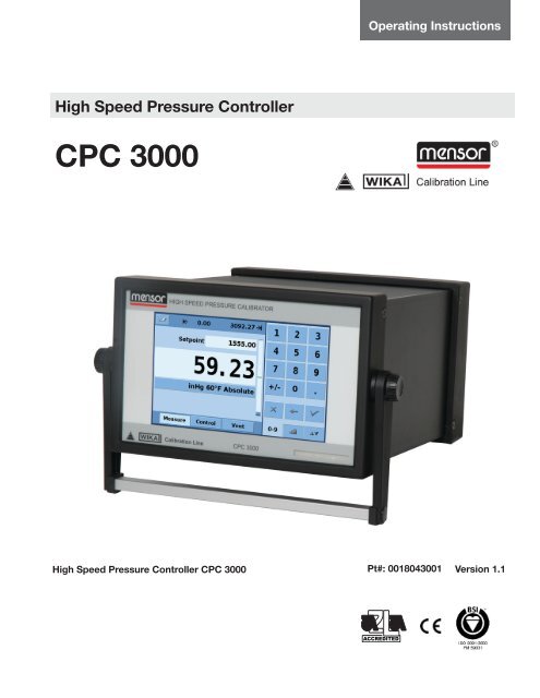
The <strong>CPC</strong> <strong>3000</strong> front panel, shown in Figure - "Front Panel", includes a 7 inch color SVGA display<br />
featuring touch screen technology. Operator input is accomplished by pressing the number, words or<br />
symbols presented on the display. There are no mechanical keypads or switches on the front panel.<br />
Figure - Front Panel<br />
Mensor / WIKA Operating Instruction <strong>High</strong> <strong>Speed</strong> <strong>Pressure</strong> <strong>Controller</strong>∙ Version 1.1 1
<strong>High</strong> <strong>Speed</strong> <strong>Pressure</strong> <strong>Controller</strong><br />
<strong>CPC</strong> <strong>3000</strong><br />
3.5 Main Menu<br />
When the <strong>CPC</strong> <strong>3000</strong> is powered up it takes about one minute for initialization, then displays a<br />
screen similar to the Figure - "Initial Screen" below.<br />
14<br />
SETUP menu<br />
Stability indication<br />
Current pressure value<br />
Bar graph<br />
<strong>Pressure</strong> Units<br />
User defined control range limits<br />
(configurable via SETUP-CONTROL)<br />
Operating mode<br />
Figure - Initial Screen<br />
3.5.1 Keys, Tabs, Check Boxes, Labels/Graphics:<br />
�<br />
�<br />
�<br />
�<br />
Numeric keypad<br />
Jog key pad selection tab<br />
Step key pad selection tab<br />
Numeric key pad selection tab<br />
Delete selected set point<br />
Delete last entered digit<br />
Accept selected set point<br />
Keys: There are two types of keys: those that act as a switch to change a condition and<br />
those that open a data entry screen when pressed. Keys have borders with a three dimensional,<br />
shadowed effect (examples: , ). Throughout this<br />
manual keys are represented with the displayed characters enclosed in brackets ( Example<br />
[MEASURE] ) or a description and the actual graphic icon ( Example [SETUP] ). Pressing<br />
a key will have one of the following results: 1) instant, single step response, 2) continu-<br />
ously repeating steps while the key is held down, 3) the key will change colors indicating that<br />
the associated function is active or 4) a data entry dialog box will open. Operators will quickly<br />
become accustomed to the particular characteristics of the frequently used keys.<br />
Tabs: Tabs are analogous to tabs in a notebook that allow switching quickly between related<br />
screens. Tabs are keys that allow the operator to switch between a group of screens that have a<br />
similar purpose, for example the tabs allow the operator to quickly switch between<br />
three screens used to enter the setpoint.<br />
Check Boxes: Check Boxes allow for the inclusion or exclusion of specific elements or<br />
conditions.<br />
Labels and Graphics: Labels and Graphics are text, or graphic that display information, but<br />
do not respond to being touched (examples: ). They indicate choices<br />
that have been made in the setup menus or indicate existing conditions as pressure is controlled or<br />
measured.<br />
Mensor / WIKA Operating Instruction <strong>High</strong> <strong>Speed</strong> <strong>Pressure</strong> <strong>Controller</strong>∙ Version 1.1
<strong>High</strong> <strong>Speed</strong> <strong>Pressure</strong> <strong>Controller</strong><br />
<strong>CPC</strong> <strong>3000</strong><br />
3.6 Front Panel Variations and Navigation<br />
Bar Graph: The bar graph shows the relative indication of the range of the internal sensor, the<br />
user defined limits on the internal sensor, the unused portion of the internal pressure sensor<br />
range, the setpoint and the magnitude of the actual controlled pressure. The user defined control<br />
limits can be selected in the Main->Setup->Control screen and can be set to correspond to the<br />
range of the device under test. It is important to note that when the STEP key pad is active in<br />
percent mode each step is a percent of the user defined limit not the full scale of the internal<br />
sensor. This is useful when calibrating or testing various range devices. Figure "Bar Graph"<br />
shows the Bar Graph when the <strong>CPC</strong> <strong>3000</strong> is in control mode controlling a pressure at the setpoint.<br />
Bar graph shows relative indication of:<br />
•<br />
•<br />
•<br />
•<br />
•<br />
Figure - Bar Graph<br />
3.6.1 Operating mode (press to select mode):<br />
�<br />
�<br />
�<br />
Range of the Internal sensor<br />
User defined limits<br />
Unused portion of the internal<br />
sensor range<br />
Setpoint<br />
Current pressure reading<br />
MEASURE<br />
In MEASURE mode, the instrument measures the pressure connected to the MEASURE port<br />
(on changing from CONTROL mode: the last controlled pressure will be held/sealed in the<br />
connected test assembly).<br />
CONTROL<br />
In CONTROL mode the instrument provides a very precise pressure at the MEASURE port.<br />
VENT<br />
VENT opens measure port to atmospheric pressure.<br />
Mensor / WIKA Operating Instruction <strong>High</strong> <strong>Speed</strong> <strong>Pressure</strong> <strong>Controller</strong>∙ Version 1.1 15
<strong>High</strong> <strong>Speed</strong> <strong>Pressure</strong> <strong>Controller</strong><br />
<strong>CPC</strong> <strong>3000</strong><br />
Optional elements can be chosen in the [SETUP-DISPLAY] screen explained in section 7.8.1 of<br />
this manual. Each optional element is displayed in the area below the pressure units.<br />
16<br />
Area for optional elements<br />
Communication status Optional barometric<br />
reference display<br />
Figure-Optional Display elements<br />
Navigation to the SETUP screens is achieved pressing the Icon. Setup Figure "Main Setup<br />
Screen" shows the setup screen with the display table activated. Other tabs at the bottom are<br />
used to navigate to additional setup screens. Setup screens will be discussed in detail in section<br />
7.8 of this manual.<br />
Figure - Main Setup Screen<br />
Mensor / WIKA Operating Instruction <strong>High</strong> <strong>Speed</strong> <strong>Pressure</strong> <strong>Controller</strong>∙ Version 1.1
<strong>High</strong> <strong>Speed</strong> <strong>Pressure</strong> <strong>Controller</strong><br />
<strong>CPC</strong> <strong>3000</strong><br />
3.7 Main menu setpoint entry options<br />
<strong>Pressure</strong> setpoint entry options are chosen using the tab keys .<br />
Figure - Numeric Keypad<br />
Figure "Numeric Keypad" shows the main menu with the numeric keypad selected.<br />
Figure - Step Keypad<br />
Figure "Step Keypad" shows the main menu with the step keypad selected.<br />
Figure - Jog Keypad<br />
Figure "Jog Keypad" shows the main menu with the jog keypad selected.<br />
Mensor / WIKA Operating Instruction <strong>High</strong> <strong>Speed</strong> <strong>Pressure</strong> <strong>Controller</strong>∙ Version 1.1 17
<strong>High</strong> <strong>Speed</strong> <strong>Pressure</strong> <strong>Controller</strong><br />
<strong>CPC</strong> <strong>3000</strong><br />
4. Specifications<br />
Specifications Unit <strong>CPC</strong> <strong>3000</strong><br />
<strong>Pressure</strong> ranges psi<br />
18<br />
Gauge: 0 ... 5 up to 0 ... 1000 psig<br />
Absolute: 0 ... 15 to 0 ... 1015 psia<br />
<strong>Pressure</strong> ranges, bi-directional psi (mbar) Minimum span 5 (350)<br />
<strong>Pressure</strong> types Absolute and gauge or bi-directional ranges<br />
Precision % FS < 0.004<br />
Total uncertainty % FS < 0.025<br />
Compensated temp range °C 15 to 45<br />
Calibration Interval Year 1<br />
<strong>Pressure</strong> units: English<br />
<strong>Pressure</strong> units: Metric<br />
<strong>Pressure</strong> units user defined 2 (multiplier from psi or Pascal)<br />
Control stability % FS < 0.004 (of the internal sensor range)<br />
Slew rate sec.<br />
Control range From 0 up to 100 % FS<br />
psi, psf, osi, tsi, tsf, atm, inHg 0˚C, inHg 60˚F, mtorr, torr, inSW, ftSW, inH O<br />
4˚C, inH O 20˚C, inH O 60˚F, ftH O 4˚C, ftH O 20˚C, ftH O 60˚F<br />
mbar, bar, gm/cm , kg/cm , kg/m , Dy/cm , pascal, hPa, kPa, MPa,<br />
mmHg 0˚C, cmHg 0˚C, mHg 0˚C, mSW, mmH O 4˚C, cmH O 4˚C, mH O 4˚C,<br />
mmH O 20˚C, cmH O 20˚C, mH O 20˚C<br />
< 3 (up or downscale into a 250 ml test volume to within 0.025%FS of the<br />
setpoint for pressures above 700 mbar.)<br />
Minimum control pressure 0.05% FS or 0.025 psi over exhaust pressure, whichever is greater.<br />
Overshoot %FS
<strong>High</strong> <strong>Speed</strong> <strong>Pressure</strong> <strong>Controller</strong><br />
<strong>CPC</strong> <strong>3000</strong><br />
5. Installation<br />
5.1 Introduction<br />
The initial installation of the <strong>CPC</strong> <strong>3000</strong> includes the following steps: Unpack the system, place it in<br />
a suitable workspace, connect it, switch it on and configure.<br />
5.2 Unpacking the system<br />
Unpack all components of the <strong>CPC</strong> <strong>3000</strong> carefully and check for damage. Report any damage<br />
immediately to the forwarding agent.<br />
Apart from any additional components ordered, a shipment consists of:<br />
�<br />
�<br />
�<br />
�<br />
�<br />
�<br />
<strong>CPC</strong> <strong>3000</strong> controller<br />
1/4" and 6mm tube fitting adapters<br />
Power cable<br />
Manual<br />
Calibration certificate<br />
Optional: recommend Interface cable or any other accessories ordered<br />
5.3 Dimensions in Inches<br />
5 1/4<br />
8 /8 1<br />
Front view Side view<br />
Rear view<br />
The instrument can be set up on a table top or it can be rack-mounted. Rack mount adapters are<br />
optional on the <strong>CPC</strong> <strong>3000</strong> and require an adapter panel.<br />
Mensor / WIKA Operating Instruction <strong>High</strong> <strong>Speed</strong> <strong>Pressure</strong> <strong>Controller</strong>∙ Version 1.1 19
<strong>High</strong> <strong>Speed</strong> <strong>Pressure</strong> <strong>Controller</strong><br />
<strong>CPC</strong> <strong>3000</strong><br />
5.4 Installation<br />
The installation site must meet the following conditions:<br />
� Operating Temperature: 10 to 50 �C °C<br />
� Humidity: 35 to 85 % relative humidity non-condensation<br />
� Flat, horizontal location; secure fixed working surface (desk top model) or installation in a 19"<br />
rack mount.<br />
� At the back of the instrument sufficient air circulation must be provided for to avoid an accumulation<br />
of the heat conducted to the outside via the fan.<br />
� During operation, pressure escapes through the vent port in the back of the instrument. Personnel<br />
should not have access to the rear vent and exhaust port during operation.<br />
Avoid the following influences:<br />
�<br />
�<br />
�<br />
�<br />
�<br />
�<br />
Direct sunlight or proximity to hot objects<br />
Unstable installation position<br />
Mechanical vibration<br />
Proximity to sources of strong electromagnetic fields, such as high tension appliances, mobile<br />
telephones or mains<br />
Soot, steam, dust and corrosive gases<br />
Environment with explosion hazard, inflammable atmospheres<br />
<strong>Pressure</strong> supply requirements:<br />
�<br />
�<br />
�<br />
Stable supply pressure 10% higher than the full scale of the internal transducer<br />
Permissible media: dry, clean air or nitrogen<br />
Vacuum: min. 50 litres/min (if required)<br />
20<br />
i<br />
Notice<br />
!<br />
Warning<br />
An angle of inclination of the system of more than 3 degrees can cause a deviation<br />
in the measured pressure and should be avoided. Zeroing the unit at the angle of<br />
inclination will nullify this deviation.<br />
Applying supply pressure higher than the recommended pressure can cause<br />
permanent damage to the controller!<br />
Mensor / WIKA Operating Instruction <strong>High</strong> <strong>Speed</strong> <strong>Pressure</strong> <strong>Controller</strong>∙ Version 1.1
<strong>High</strong> <strong>Speed</strong> <strong>Pressure</strong> <strong>Controller</strong><br />
<strong>CPC</strong> <strong>3000</strong><br />
5.5 Rear panel<br />
Four pneumatic pressure ports are located on the rear panel (see below: Figure - "Rear panel").<br />
Positioned on the left are the ethernet and RS-232 and GPIB connector, the off/on switch, the line<br />
fuses, and a protective grill covering the ventilating fan.<br />
5.6 <strong>Pressure</strong> connections<br />
!<br />
Warning<br />
i<br />
Notice<br />
Figure - Rear panel<br />
The pressure connections must be installed according to the following instructions,<br />
observing the relevant regulations. The installation should be performed<br />
by persons familiar with, and who can work according to, the safety regulations<br />
for working on pneumatic/hydraulic systems.<br />
When making up a connection to an o-ring adapter port use a back-up wrench to<br />
prevent over-stressing the threads in the manifold block.<br />
All of the pressure ports on the rear are female 7/16 - 20 SAE/MS straight threads per MS16142<br />
and SAE J514 table 14. They require a tube fitting boss seal with an o-ring per MS33656. Mensor<br />
provides female 1/4 inch and 6 mm tube fittings with the instrument. The pressure connections<br />
can be made to these adapters with the proper mating hardware. Do not use sealant on fittings<br />
sealed with an o-ring.<br />
Mensor / WIKA Operating Instruction <strong>High</strong> <strong>Speed</strong> <strong>Pressure</strong> <strong>Controller</strong>∙ Version 1.1 1
<strong>High</strong> <strong>Speed</strong> <strong>Pressure</strong> <strong>Controller</strong><br />
<strong>CPC</strong> <strong>3000</strong><br />
5.7 Function of pressure connections<br />
�<br />
�<br />
�<br />
�<br />
�<br />
MEASURE/CONTROL port<br />
Below the label "MEASURE/CONTROL" is a pressure connection. In MEASURE mode<br />
this connection connects the pressure applied to the internal sensor where the pressure is<br />
measured (within the range of the internal sensor). In CONTROL mode this connection supplies<br />
an output pressure controlled by the internal regulator at the commanded setpoint.<br />
SUPPLY port<br />
Below the label "SUPPLY" is a pressure connection. This connection should be supplied with a<br />
pressure that is approximately equal to 110% of the full scale pressure of the internal sensor. In<br />
other words, 10% above the full scale pressure of the internal sensor (see “Supply <strong>Pressure</strong>” in<br />
the specifications section for supply pressure and pressure media requirements.)<br />
EXHAUST/VACUUM port<br />
Below the label "EXHAUST/VACUUM" is a pressure connection. If a sub-atmospheric control<br />
pressure is required a vacuum pump must be connected to this port. Otherwise, this port may<br />
be left open to atmosphere.<br />
!<br />
Warning<br />
The user must use caution when controlling from a very high pressure down<br />
to a very low pressure when a vacuum pump is connected to the exhaust port.<br />
Large volumes of gas may be present in the device under test and will exhaust<br />
through the Vacuum/Exhaust port in excess of the capacity of the internal<br />
relief valve, possibly causing damage to the vacuum pump.<br />
VENT outlet<br />
Below the Label "VENT" is the pressure outlet. In VENT mode the pressure within the system is<br />
released through this outlet.<br />
!<br />
Warning<br />
HIGH SOUND LEVELS! <strong>Pressure</strong>s from 600 psig and up can generate sound<br />
levels above 100 db for brief periods when they are exhausted directly to<br />
atmosphere. If no muffling devices are attached to the exhaust/vent port, then<br />
ear protection is advised for personnel in the vicinity of the instruments that<br />
will be operated under such conditions.<br />
REFERENCE port<br />
On gauge units this port is connected to the reference side of the transducer, and on absolute<br />
units it is internally capped. This port is normally left open to atmosphere but may be attached<br />
to a snubber assembly on very low pressure instruments.<br />
!<br />
Warning<br />
The controller must be protected from over pressure.<br />
Pipes, couplings and other components used for connecting the supply<br />
exhaust and the Measure/Control port must be suitable for the application and<br />
rated for the applied pressures.<br />
The user must ensure that the pressure media are clean and dry. If necessary,<br />
the internal sensors and mechanisms must be protected by using a liquid trap<br />
or coalescing filter.<br />
Mensor / WIKA Operating Instruction <strong>High</strong> <strong>Speed</strong> <strong>Pressure</strong> <strong>Controller</strong>∙ Version 1.1
<strong>High</strong> <strong>Speed</strong> <strong>Pressure</strong> <strong>Controller</strong><br />
<strong>CPC</strong> <strong>3000</strong><br />
5.8 Electrical connections<br />
!<br />
Warning<br />
The electrical installation has to be performed according to the following<br />
instructions while observing the relevant regulations. It is to be carried out by<br />
a qualified electrician.<br />
5.8.1 Connecting the power supply and turning on the instrument<br />
!<br />
Warning<br />
Before connecting the power supply, make sure that the supply voltage agrees<br />
with the specification of the power unit. Switch off the system before connecting<br />
the power via the power switch at the rear of the instrument.<br />
Only the power cable supplied should be used.<br />
The 3-pin power cable supplied is fitted with a ground lead. Operate the<br />
system only from a 3-pin socket and always make sure that the ground lead is<br />
properly connected.<br />
The power input socket is to be connected according to the regulations with the country-specific<br />
connection cable supplied to a power supply that lies within the required specification. To poweron<br />
the instrument switch the power switch ON (located on the rear of the instrument; also see<br />
chapter 6 "Starting operation").<br />
5.8.2 Connecting the Communications interfaces<br />
USB 2.0 FS Interface<br />
The USB 2.0 FS connection on the rear panel of the <strong>CPC</strong><strong>3000</strong> is a USB-B Type connector. The<br />
manufacturer of the USB interface board provides the drivers and product information on a CD<br />
that is included with the <strong>CPC</strong><strong>3000</strong>.<br />
IEEE-488 Interface (GPIB)<br />
The connection of the IEEE-488 interface is designed as a 24-pin IEEE-488-socket.<br />
The manufacturer of the host IEEE-488 interface board provides software to allow communication<br />
between the board and various programming languages.<br />
An interactive program for debugging is usually provided as well. Refer to the board manufacturer’s<br />
documentation for more information.<br />
Mensor / WIKA Operating Instruction <strong>High</strong> <strong>Speed</strong> <strong>Pressure</strong> <strong>Controller</strong>∙ Version 1.1
<strong>High</strong> <strong>Speed</strong> <strong>Pressure</strong> <strong>Controller</strong><br />
<strong>CPC</strong> <strong>3000</strong><br />
ETHERNET Interface<br />
The ethernet communication port allows the <strong>CPC</strong> <strong>3000</strong> to communicate with computers using<br />
10/100 Based-T specifications.<br />
4<br />
!<br />
Warning<br />
Please consult your Computer Resources Department prior to connecting<br />
this instrument to your network to verify there are no conflicts with existing IP<br />
addresses.<br />
Ethernet communications are transmitted over a standard RJ-45 cable.<br />
Prior to first time use of ethernet communication, the four parameters, IP, Netmask, Gateway, and<br />
Port must be setup. These are configured in the communications setup screen.<br />
Mensor / WIKA Operating Instruction <strong>High</strong> <strong>Speed</strong> <strong>Pressure</strong> <strong>Controller</strong>∙ Version 1.1
<strong>High</strong> <strong>Speed</strong> <strong>Pressure</strong> <strong>Controller</strong><br />
<strong>CPC</strong> <strong>3000</strong><br />
6. Starting operation<br />
!<br />
Warning<br />
Before the system is switched on, verify that the system was installed according<br />
to the instructions of the previous section and that all connections installed<br />
are fitted according to the current regulations.<br />
Operators must ensure that all specifications that apply to supply voltage,<br />
operating temperature, humidity, pressure media and pressure ranges are<br />
observed.<br />
Condensation can occur inside the system when the temperature changes<br />
abruptly. Give the system sufficient time for acclamation in such cases.<br />
Before pressurizing, the operator must ensure that the system and the device<br />
under test will not be over pressurized. When working with or on the instrument,<br />
safety glasses should be worn.<br />
In the rooms in which the <strong>CPC</strong> <strong>3000</strong> is operated sufficient air ventilation has to<br />
be ensured.<br />
When the above points have been met you can switch on the system, (the switch is located on<br />
the rear of the instrument) and configure it as required after you have familiarized yourself with the<br />
operation (see section: "Operation (via Touch-screen)"). After turning the power switch to ON, the<br />
instrument will go through a brief initialization process and system check, which will take about<br />
40 seconds. As soon as the system check is completed the system will default to an operating<br />
screen similar to "Figure-Initial screen" in section 3.6. Allow at least 15 minutes of warm up time to<br />
achieve thermal equilibrium between the controller and its environment before performing critical<br />
pressure measurements.<br />
Mensor / WIKA Operating Instruction <strong>High</strong> <strong>Speed</strong> <strong>Pressure</strong> <strong>Controller</strong>∙ Version 1.1 5
<strong>High</strong> <strong>Speed</strong> <strong>Pressure</strong> <strong>Controller</strong><br />
<strong>CPC</strong> <strong>3000</strong><br />
NOTES:<br />
6<br />
Mensor / WIKA Operating Instruction <strong>High</strong> <strong>Speed</strong> <strong>Pressure</strong> <strong>Controller</strong>∙ Version 1.1
<strong>High</strong> <strong>Speed</strong> <strong>Pressure</strong> <strong>Controller</strong><br />
<strong>CPC</strong> <strong>3000</strong><br />
7. Local Operation<br />
This section describes the procedures for operating the <strong>CPC</strong> <strong>3000</strong> from the front panel.<br />
�<br />
�<br />
Tabs, Keys, Value Entry and Check Boxes:<br />
Local operation is accomplished by observing the data presented in the display menus, then<br />
pressing the on-screen tab, key, value entry or check box for the desired sub-menu, function<br />
or selection. Tabs are used to access the subset of a menu, keys open new menus, make<br />
selections or change a parameter, value entry opens a keypad to enter a value, and check<br />
boxes allow choice of associated display option.<br />
Screen Hierarchy:<br />
Navigation within the <strong>CPC</strong> <strong>3000</strong> is similar to a computer file system or a web page. Keys or<br />
tabs activate sub-menus. Within the sub-menus there may be related sub-menus or selections.<br />
To return back through the hierarchy of screens the [BACK] key is provided. Throughout<br />
this manual screen hierarchy will be designated using the following convention: "main->submenu->selection"<br />
or "main->sub-menu->tab->selection. The Hierarchical menu structure is<br />
very intuitive and will become more obvious after reviewing following examples.<br />
7.1 Setting the operating language<br />
In the upper left corner of the main display is the [SETUP] key . To change the language<br />
select the [SETUP] key and select the [DISPLAY] tab if not already active. In the box labelled<br />
"view" on the upper right side of the resulting main->setup->display screen there is a [FLAG]<br />
key. Press the [FLAG] key and a selection of language keys will appear. Select the desired<br />
language. Then press the [BACK] key to return to the main menu which will now display in the<br />
selected language. Using our convention, selecting English would be described by the following:<br />
main->setup->display->flag->english<br />
7.2 Display configuration<br />
The <strong>CPC</strong> <strong>3000</strong> main menu Figure - "Main Menu" shows the main screen that appears when the<br />
unit is turned on. A point by point description of each element is shown in this figure. The setup<br />
key opens the setup menu where changes can be made and information viewed. Each submenu<br />
in the setup menu can be activated by pressing the [DISPLAY], [CONTROL], [REMOTE],<br />
[INFO] or [SERVICE] tab. Each of these setup sub-menus will be discussed in detail in chapter<br />
7.8.<br />
The points on the main menu that are independent of the setup menus are the setpoint indication,<br />
the actual pressure reading, the units of measure and the control modes (measure, control and<br />
vent), plus the three tab menus used for selecting a setpoint. The [PRESSURE UNIT]<br />
key indicates the currently chosen pressure unit and can be pressed to open a menu that allows<br />
selection of English, metric, or user defined pressure units.<br />
The <strong>CPC</strong> <strong>3000</strong> main menu shown in "Figure - Optional Elements" shows elements that can be<br />
displayed on the main menu and describes the three choices available for setpoint entry (Numeric<br />
Keypad, Step and Jog). Optional elements include the Communication status icon which indicates<br />
a connection or disconnection from a remote computer, and the barometric reference indication<br />
showing the value of the atmospheric pressure measured by the optional internal barometric reference<br />
sensor.<br />
Mensor / WIKA Operating Instruction <strong>High</strong> <strong>Speed</strong> <strong>Pressure</strong> <strong>Controller</strong>∙ Version 1.1 27
<strong>High</strong> <strong>Speed</strong> <strong>Pressure</strong> <strong>Controller</strong><br />
<strong>CPC</strong> <strong>3000</strong><br />
Setup Key<br />
Setpoint<br />
Stable Indication<br />
Current pressure value<br />
<strong>Pressure</strong> mode indication<br />
<strong>Pressure</strong> unit key<br />
Bar graph<br />
MEASURE<br />
Measure mode pneumatically connects<br />
the pressure sensor directly to the device<br />
under test. In measure mode pressure<br />
regulation is inactive.<br />
8<br />
SETUP<br />
menu<br />
<strong>Pressure</strong> emulation mode<br />
key<br />
Communication status*<br />
Optional barometric<br />
reference display*<br />
User defined DUT / control range<br />
limits (configurable via SETUP)<br />
CONTROL<br />
In the control mode, the device<br />
regulates the pressure<br />
output according to the set<br />
point value, providing a precise<br />
pressure at the test or<br />
measure port.<br />
Figure - Main Menu<br />
Figure - Optional Elements<br />
Numeric keypad<br />
Delete selected set point<br />
Delete last entered digit<br />
Accept selected set point<br />
VENT<br />
Vents the system and the device<br />
under test to atmospheric pressure.<br />
SETUP menu<br />
The SETUP menu allows<br />
access to the following tabs.<br />
Display<br />
Control<br />
Remote<br />
Info<br />
Service<br />
Mensor / WIKA Operating Instruction <strong>High</strong> <strong>Speed</strong> <strong>Pressure</strong> <strong>Controller</strong>∙ Version 1.1<br />
�<br />
�<br />
�<br />
�<br />
�<br />
Jog key pad selection tab<br />
Step key pad selection tab<br />
Numeric key pad selection tab<br />
Note: See the following page for detailed information<br />
on each set point entry screen.
<strong>High</strong> <strong>Speed</strong> <strong>Pressure</strong> <strong>Controller</strong><br />
<strong>CPC</strong> <strong>3000</strong><br />
7.3 Setpoint Entry<br />
The control setpoint can be entered using the default Numeric Keypad or the alternate Step or<br />
Jog keypads that appear on the right side of the main menu when selected using the [SETPOINT<br />
ENTRY SIDE-MENU] tabs on the lower right hand side of the main menu. These<br />
alternative methods of entering the setpoint have advantages in different situations and have been<br />
designed to increase ease of use and productivity.<br />
The Numeric Keypad shown in figure - "Numeric Keypad" to the left, is<br />
the default keypad that appears every time the unit is turned on or can be<br />
activated using the [0-9] tab. A setpoint value can be entered directly using<br />
this keypad. As the value of the setpoint is entered the setpoint field will turn<br />
blue and the entered value will appear in the field. The Setpoint value can be<br />
deleted completely using the [DELETE] key, the last digit of the entered<br />
setpoint can be deleted using the [CLEAR ENTRY] key or the setpoint<br />
value can be accepted using the [ACCEPT ENTRY] key. When the<br />
[ACCEPT ENTRY] key is pressed the setpoint field will turn white and the new<br />
setpoint will become active. In control mode, the controller output will ramp to<br />
the entered setpoint. Caution: If the [ACCEPT ENTRY] key is not pressed the<br />
previously entered setpoint will remain active.<br />
Figure - Numeric Keypad<br />
Figure - Step Keypads<br />
Figure - Jog Keypad<br />
The Step keypads shown in figure - "Step Keypads",<br />
provide a way to increment the setpoint by defined steps.<br />
Steps are a percent of the user defined limits set in the<br />
main->setup->control or actual pressure values that<br />
are displayed in the pressure units selected in the main<br />
menu. A total of 12 steps are provided. When a step is<br />
pressed the related setpoint is immediately entered as the<br />
active setpoint. In control mode, the controller output will<br />
ramp to this setpoint. The Step Keypad can be modified<br />
in the main->setup->display menu discussed in section<br />
7.8.1.<br />
The Jog Keypad shown in figure - "Jog Keypad", provides a way to jog the<br />
setpoint up or down by small increments. The increments are determined by<br />
the resolution, the maximum control limit and/or the units of measure. For<br />
example, if the resolution is set to display four decimals then the small triangle<br />
pointing up will change the setpoint by 0.0001 and the small triangle pointing<br />
down will change the setpoint by -0.0001. In the same way, the medium<br />
triangles will change the setpoint by +/- 0.0010 and the large triangles will<br />
change the setpoint by +/- 0.0100 as shown in the figure. When the Resolution,<br />
the maximum control limit or the units of measure are changed so that<br />
three decimals are displayed, then the jog functions will change to +/- 0.001,<br />
+/- 0.010 and +/- 0.100 respectively. This is useful when adjusting the controller<br />
to reach a cardinal point on a dial gauge.<br />
Mensor / WIKA Operating Instruction <strong>High</strong> <strong>Speed</strong> <strong>Pressure</strong> <strong>Controller</strong>∙ Version 1.1 9
<strong>High</strong> <strong>Speed</strong> <strong>Pressure</strong> <strong>Controller</strong><br />
<strong>CPC</strong> <strong>3000</strong><br />
7.4 Operating modes<br />
The selection keys for the operating modes Measure, Control and Vent are located at the bottom<br />
of the main menu.<br />
�<br />
[MEASURE]:<br />
In measure mode, the instrument measures the pressure connected to the MEASURE/<br />
CONTROL port. Figure -"Measure Mode" shows the state of the isolation valves in measure<br />
mode.<br />
30<br />
!<br />
Warning<br />
When the <strong>CPC</strong> <strong>3000</strong> is turned off all the valves close and could trap<br />
pressurized gas within the pneumatics. It is safe practice to vent after use<br />
and before connecting any devices to the Measure/Control port.<br />
Figure - Measure Mode<br />
Mensor / WIKA Operating Instruction <strong>High</strong> <strong>Speed</strong> <strong>Pressure</strong> <strong>Controller</strong>∙ Version 1.1
<strong>High</strong> <strong>Speed</strong> <strong>Pressure</strong> <strong>Controller</strong><br />
<strong>CPC</strong> <strong>3000</strong><br />
�<br />
[CONTROL]:<br />
In control mode the instrument provides a precise pressure output (equal to the SETPOINT +/-<br />
the stability specification) at the Measure/Control port. The indication of the current pressure<br />
value will turn green when the setpoint has been reached and the stable window settings have<br />
been satisfied. Figure -"Control Mode" shows the state of the isolation valves in measure<br />
mode. Notice that the regulator is active in the control mode.<br />
Figure - Control Mode<br />
Mensor / WIKA Operating Instruction <strong>High</strong> <strong>Speed</strong> <strong>Pressure</strong> <strong>Controller</strong>∙ Version 1.1 1
�<br />
<strong>High</strong> <strong>Speed</strong> <strong>Pressure</strong> <strong>Controller</strong><br />
<strong>CPC</strong> <strong>3000</strong><br />
[VENT]:<br />
Vent mode vents the pneumatic system and shuts off the supply. Figure -"vent mode" shows<br />
the state of the isolation valves in vent mode.<br />
Figure - Vent Mode<br />
Mensor / WIKA Operating Instruction <strong>High</strong> <strong>Speed</strong> <strong>Pressure</strong> <strong>Controller</strong>∙ Version 1.1
<strong>High</strong> <strong>Speed</strong> <strong>Pressure</strong> <strong>Controller</strong><br />
<strong>CPC</strong> <strong>3000</strong><br />
7.5 Data Entry<br />
When there is a requirement to enter specific<br />
numeric or alpha values into the system, the<br />
method of entry is consistent for all instances.<br />
When a [VALUE ENTRY] key is pressed a dialog<br />
box will appear similar to Figure - "Value Entry".<br />
This Value Entry Dialog box will have a numeric<br />
or alpha keypad, when appropriate minimum<br />
and maximum value limits, current value and<br />
a window that shows the new value entered.<br />
The value can be deleted completely using the<br />
[DELETE] key, the last digit of the entered<br />
setpoint can be deleted using the [CLEAR<br />
ENTRY] key or the setpoint value can be<br />
accepted using the [ACCEPT ENTRY] key.<br />
7.6 "<strong>Pressure</strong> unit", "pressure mode" and "emulation mode"<br />
Figure - Value Entry<br />
The <strong>Pressure</strong> [UNIT] key is shown on the main screen below the current pressure value and<br />
displays the most recently chosen pressure units and the mode (absolute or gauge). If the optional<br />
barometric reference is installed a [MODE] key replaces the mode indication to the right of the<br />
units key. This [MODE] key indicates absolute or gauge mode. When the key is pressed it will<br />
switch between the "native mode" of the internal sensor to the emulation mode. The "native<br />
mode" is the mode of the sensor that is installed and is either absolute or gauge. Emulation mode<br />
uses the value of the barometric reference to emulate the mode that is alternate to the native<br />
mode. The <strong>CPC</strong> <strong>3000</strong> can emulate gauge from a native absolute sensor or absolute from a native<br />
gauge sensor. The [MODE] key indicates the native mode with a blue key background and emulation<br />
mode with a light blue key background. The units and mode chosen remain the same when<br />
the <strong>CPC</strong> <strong>3000</strong> is turned off then back on.<br />
Native sensor is gauge, no barometric reference installed.<br />
Native sensor is gauge, barometric reference installed.<br />
Native sensor is gauge, barometric reference installed and<br />
absolute emulation active.<br />
Pressing the [UNITS] Key will open a dialog box that shows the available pressure units with a<br />
tabs for [ENGLISH], [METRIC] and [USER UNITS] units. Pressing a tab will open a menu with the<br />
related set of units available. The [USER UNITS] tab menu includes [USER 1] and [USER 2] keys<br />
and allows the user to enter customized pressure units. Press the [MULTIPLIER VALUE] key to<br />
enter a multiplier that defines the user unit as the multiplier times one psi or one Pascal, whichever<br />
is currently pressed.<br />
Mensor / WIKA Operating Instruction <strong>High</strong> <strong>Speed</strong> <strong>Pressure</strong> <strong>Controller</strong>∙ Version 1.1
<strong>High</strong> <strong>Speed</strong> <strong>Pressure</strong> <strong>Controller</strong><br />
<strong>CPC</strong> <strong>3000</strong><br />
A gray background on a [PRESSURE UNITS] key indicates that it is the current selection. Touch<br />
any other [PRESSURE UNITS] key, and press [BACK] key to enable change and return to previous<br />
operation screen. All of the displayed pressure values will have changed to correspond to the<br />
newly selected units.<br />
7.7 Bar Chart<br />
The Bar chart shows the relative indication<br />
of the current pressure value with<br />
respect to the full scale value of the<br />
internal sensor and the user defined<br />
minimum and maximum limits (see<br />
section 7.8.7 for setup of user defined<br />
limits). The full height of the bar graph<br />
is proportional to the internal sensor<br />
range. The green line indicates the<br />
magnitude of the setpoint. The blue<br />
column indicates the magnitude of the<br />
current pressure. The cross hatched<br />
section indicates the portion of the<br />
internal sensor above or below the user<br />
defined limits that is not being used.<br />
7.8 Setup Menus<br />
4<br />
internal sensor range<br />
The setup menus are opened by pressing the [SETUP] key. This opens the menu shown in<br />
Figure - "Setup". The setup menu has five tabs: [DISPLAY], [CONTROL], [REMOTE], [INFO] and<br />
[SERVICE]. Each tab is described in detail in the following sections. The screen below has the<br />
[DISPLAY] tab active.<br />
Figure - "Setup"<br />
portion of the internal sensor range<br />
outside of the user defined limits<br />
User defined limits<br />
Current pressure Setpoint (green line)<br />
Mensor / WIKA Operating Instruction <strong>High</strong> <strong>Speed</strong> <strong>Pressure</strong> <strong>Controller</strong>∙ Version 1.1
<strong>High</strong> <strong>Speed</strong> <strong>Pressure</strong> <strong>Controller</strong><br />
<strong>CPC</strong> <strong>3000</strong><br />
7.8.1 Setup Display<br />
The main->setup->display menu contains elements that change the appearance and function of<br />
components displayed on the main menu. Following is a description of the elements of this menu.<br />
�<br />
�<br />
�<br />
�<br />
�<br />
�<br />
Filter: The filter selection keys [LOW], [NORMAL], and [HIGH] dampen the pressure<br />
display to reduce the affect of pneumatic noise associated with the device under test<br />
or the test environment.<br />
Resolution: The resolution section of the Setup Display menus allows the user to<br />
change the resolution of the current pressure reading to be [4], [5] or [6] digits.<br />
Stable Window and Delay: The stable window is the percentage of the full scale<br />
value of the internal sensor that the current pressure can deviate +/- from the setpoint<br />
and still display a stable indication. The stable delay is the number of seconds that<br />
the instrument must remain within the stable window before the stable indication is<br />
displayed.<br />
Language: The "view" Section of the setup display menu shows a flag, a country<br />
and a language on a key. This is the current language. Press this key to access a<br />
menu containing other languages that are available. Languages that are currently<br />
available are: American English, British English, French, German, Spanish and Italian.<br />
Additional Languages will be added as required. Figure "languages" below shows the<br />
language selection screen.<br />
Figure - Languages.<br />
Remote Status Checkbox: The Remote status check box enables or disables the<br />
remote status icon on the main menu. This icon will show a broken wire when there is<br />
no connection to a remote computer or a connected wire if the computer is connected.<br />
Barometer (optional): The Barometer check box enables or disables the indication of<br />
the barometric pressure on the main menu.<br />
Mensor / WIKA Operating Instruction <strong>High</strong> <strong>Speed</strong> <strong>Pressure</strong> <strong>Controller</strong>∙ Version 1.1 5
<strong>High</strong> <strong>Speed</strong> <strong>Pressure</strong> <strong>Controller</strong><br />
<strong>CPC</strong> <strong>3000</strong><br />
7.8.2 Setup Control<br />
Configuration of parameters associated with setting limits and adjusting parameters used to<br />
control pressure are configured in the Main->Setup->Control menu shown in<br />
Figure - "Setup Control".<br />
6<br />
�<br />
�<br />
Figure - Setup Control<br />
Maximum and Minimum Control Limits: The [DATA ENTRY] keys next to the<br />
[MINIMUM] and [MAXIMUM] labels in Figure - "Setup Control" allow the operator to<br />
select any range within the full scale range of the internal sensor. This is the "user<br />
defined range". For example: if the <strong>CPC</strong> <strong>3000</strong> has a 0-5 psi internal sensor, the user<br />
can define a range of 0-4 psi. When the user defined range is changed, a corresponding<br />
change occurs in the step menu so that the percent step will equal the corresponding<br />
value within the user defined range. For example: the 80% value of a 0-4<br />
psi user defined range will be 3.2 psi but for a user defined range of 0-2 the 80%<br />
value equals 1.6 psi. The user defined range can be set to the same range as the<br />
pressure device being tested. This useful when there is a test that requires<br />
calibration at intervals equal to a percentage of the range. Each individual step<br />
can also be changed by pressing the [step] key and entering a new value.<br />
PSI or %FS: The [SELECTED UNITS] and [%FS] keys<br />
switch the step keypad display in the main menu and on the setup screen from the<br />
user selected units to percent of the full scale of the user defined range. The values<br />
when shown in the [SELECTED UNITS] mode correspond to the values in the [%FS]<br />
mode. For example, in Figure - "PSI Mode",<br />
the [PSI] key is pressed and the value shown in<br />
the 100% step is 4.0000 corresponding to the<br />
maximum limit chosen in this same screen.<br />
Individual steps in %FS or Selected Units mode can be included<br />
or excluded from the step menu by changing the [Check Box]<br />
next to the step.<br />
Figure - "PSI Mode"<br />
Mensor / WIKA Operating Instruction <strong>High</strong> <strong>Speed</strong> <strong>Pressure</strong> <strong>Controller</strong>∙ Version 1.1
<strong>High</strong> <strong>Speed</strong> <strong>Pressure</strong> <strong>Controller</strong><br />
<strong>CPC</strong> <strong>3000</strong><br />
�<br />
7.8.3 Setup Remote<br />
[Preset Points] allows the operator to select the number of points that appear as<br />
steps. For example: in Figure - "preset points" [5] is entered as the preset points<br />
value, this automatically configures 5 points from 0 to 100% of user defined range. It<br />
automatically calculates the steps that populate the step keypad in the main menu.<br />
Figure - preset points<br />
Configuration of parameters associated with remote communication are set up in the<br />
Main->Setup->Remote screen. Detailed information on setup of Ethernet USB and IEEE-488 are<br />
given in section 8 "Remote Operation".<br />
�<br />
Figure - setup remote<br />
The ethernet setup key opens a dialog box where host name, IP, netmask, gateway,<br />
port, and client IP can be entered. There is also a check box that will activate<br />
(checked) or deactivate (unchecked) Dynamic Host Configuration Protocol (DHCP).<br />
DHCP is a protocol used by networked devices (clients) to obtain the parameters<br />
Mensor / WIKA Operating Instruction <strong>High</strong> <strong>Speed</strong> <strong>Pressure</strong> <strong>Controller</strong>∙ Version 1.1 37
<strong>High</strong> <strong>Speed</strong> <strong>Pressure</strong> <strong>Controller</strong><br />
<strong>CPC</strong> <strong>3000</strong><br />
8<br />
�<br />
�<br />
�<br />
7.8.4 Setup Info<br />
necessary for operation in an Internet Protocol network. This protocol reduces system<br />
administration workload, allowing devices to be added to the network with little or no<br />
manual configuration.<br />
The USB setup key opens a dialog box where baud rate (9600, 19200, 38400, 57600,<br />
or 115200), data bit (7 or 6), stop bit (1 or 2), parity (none, odd or even) can be<br />
chosen. There is also a check box that turns echo on (checked) or off (unchecked).<br />
The IEEE address data entry button when pressed will open a data entry dialog box<br />
where the IEEE address can be entered.<br />
In the Communication section there are three remote command set emulation<br />
settings. The [MENSOR] key enables the standard mensor command set, the<br />
[SCPI WIKA] key enables the WIKA SCPI (Standard Commands for Programmable<br />
Instrumentation) command set structure, and the [DPI510] key enables the command<br />
set that will communicate with the Druck DPI 500 series of controllers. In this section<br />
there is also a [REMOTE MONITOR] key that will open a screen that shows the most<br />
recent commands and responses sent and received plus any errors. Details of each<br />
command set are given in section 8.5.<br />
The Main->Setup->Info screen, Figure - "setup info", provides Mensor contact information plus<br />
the Model number, serial number, min and max range and the native pressure units of the internal<br />
sensor, date of calibration and the software version installed. This is an information screen only<br />
and does not contain any interactive keys.<br />
Figure - Setup Info<br />
Mensor / WIKA Operating Instruction <strong>High</strong> <strong>Speed</strong> <strong>Pressure</strong> <strong>Controller</strong>∙ Version 1.1
<strong>High</strong> <strong>Speed</strong> <strong>Pressure</strong> <strong>Controller</strong><br />
<strong>CPC</strong> <strong>3000</strong><br />
7.8.5 Setup Service<br />
The setup service screen is a password protected area where calibration of the sensor and setup<br />
of the regulator is acomplished.<br />
Figure - Setup Service<br />
The setup service screen allows zero adjustment without entering the password. A zero adjustment<br />
screen, Figure - "Zero", opens when the [Zero] button is pressed. A new zero value can be<br />
entered in this screen.<br />
Figure - Zero<br />
Mensor / WIKA Operating Instruction <strong>High</strong> <strong>Speed</strong> <strong>Pressure</strong> <strong>Controller</strong>∙ Version 1.1 9
<strong>High</strong> <strong>Speed</strong> <strong>Pressure</strong> <strong>Controller</strong><br />
<strong>CPC</strong> <strong>3000</strong><br />
To access the password protected portion of the setup service screen press the key. This<br />
opens a password entry screen, Figure - "Password", where the password can be entered. Entering<br />
the password will open the setup service screen, Figure - "setup service unlocked", and allow<br />
access to all the setup options.<br />
40<br />
Figure - Password<br />
Figure - Setup Service Unlocked<br />
Mensor / WIKA Operating Instruction <strong>High</strong> <strong>Speed</strong> <strong>Pressure</strong> <strong>Controller</strong>∙ Version 1.1
<strong>High</strong> <strong>Speed</strong> <strong>Pressure</strong> <strong>Controller</strong><br />
<strong>CPC</strong> <strong>3000</strong><br />
After the password has been entered the Setup Service screen allows access to the Calibrate,<br />
Seal Point, Linerize, and Adaptation screens.<br />
!<br />
Warning<br />
Consult factory before changing any Seal Point, Linerization or Adaptation<br />
parameters.<br />
Press the [Calibrate] key to access the calibrate screen, Figure - "Calibrate Data".<br />
Figure - Calibrate Data<br />
The Calibrate screen contains three tabs: Data, Edit and Calibrate. When entering the calibrate<br />
screen the first time the Data Screen is the default. The Data screen allows changes to be made to<br />
the Zero, Span, Date of calibration and displays the sensor reading.<br />
The screen accessed by pressing the [Edit] Tab, Figure - "Calibration Edit", allows calibration<br />
using data available from a previous calibration. An example of this is when an As-Found calibration<br />
is performed and the applied and measured pressures from the calibration are available. The<br />
low true pressure should be less than 20% FS and the high true pressure should be greater than<br />
80% FS for best results. To edit the calibration from known data, enter the applied pressures in the<br />
Desired column and the measured pressures in the Actual column by pressing the number to be<br />
adjusted. When the values are changed, a new key “Apply” will appear on the screen. Press the<br />
Apply key to save the calibration data.<br />
Mensor / WIKA Operating Instruction <strong>High</strong> <strong>Speed</strong> <strong>Pressure</strong> <strong>Controller</strong>∙ Version 1.1 41
<strong>High</strong> <strong>Speed</strong> <strong>Pressure</strong> <strong>Controller</strong><br />
<strong>CPC</strong> <strong>3000</strong><br />
4<br />
Figure - Calibration Edit<br />
The Screen accessed by pressing the [Calibrate] tab, Figure - "Calibrate Calibrate", allows<br />
the operator to perform a live calibration while connected directly to a primary standard. In this<br />
mode, the <strong>CPC</strong> <strong>3000</strong> will display the currently measured pressure in the Actual column when the<br />
measured pressure is within a few percent of the value in the Desired column. The Desired column<br />
allows the actual pressures applied to the <strong>CPC</strong> <strong>3000</strong> to be entered. Press the Apply key to save<br />
changes. For best results, the two points should be as near the endpoints of the sensor’s calibration<br />
as possible. When calibrating an absolute transducer, set the low calibration point at or above<br />
a pressure of 300 millitorr. At or above that pressure the system will have a viscous flow so that the<br />
entire system should have the same pressures after a few minutes.<br />
Figure - Calibrate Calibrate<br />
Mensor / WIKA Operating Instruction <strong>High</strong> <strong>Speed</strong> <strong>Pressure</strong> <strong>Controller</strong>∙ Version 1.1
<strong>High</strong> <strong>Speed</strong> <strong>Pressure</strong> <strong>Controller</strong><br />
<strong>CPC</strong> <strong>3000</strong><br />
8. Remote Operation<br />
When the instrument is turned on, BIOS routines test the system CPU board. These tests may<br />
take up to 60 seconds. After the BIOS tests, LINUX is loaded. LINUX will then call the executable<br />
file via a batch file. The executable file will go through a series of software and hardware initialization.<br />
The following hardware/software is initialized:<br />
�<br />
�<br />
�<br />
�<br />
�<br />
�<br />
�<br />
�<br />
�<br />
Transducer: The system transducer is initialized. The transducer RAM data is transferred<br />
to system RAM.<br />
GPIB: The GPIB board is initialized as a talker/listener.<br />
Units: The scale factors for percent full scale and counts are calculated.<br />
USB: The external USB port is initialized.<br />
Valves: The pressure control algorithm is initialized.<br />
Options: Any optional hardware/software is initialized.<br />
Interrupts: Interrupt vectors are loaded and enabled.<br />
After initialization, the program enters a polled loop.<br />
The proprietary calibration constants and current settings are stored in a non-volatile<br />
device.<br />
The <strong>CPC</strong> <strong>3000</strong> system software is stored on a disk module installed in the electrical module. The<br />
program is written predominately in the C++ language. The source code conforms to all Mensor<br />
Design Engineering Group Software Standard Operating Procedures available at the time of<br />
coding. The source code is not provided on disk.<br />
Mensor / WIKA Operating Instruction <strong>High</strong> <strong>Speed</strong> <strong>Pressure</strong> <strong>Controller</strong>∙ Version 1.1 4
<strong>High</strong> <strong>Speed</strong> <strong>Pressure</strong> <strong>Controller</strong><br />
<strong>CPC</strong> <strong>3000</strong><br />
8.1 Remote Setup<br />
To setup any of the remote communication protocols start in the setup remote screen, Figure -<br />
"Setup Remote".<br />
8.2 Remote Setup – Ethernet<br />
44<br />
Figure - Setup Remote<br />
The Ethernet communication port allows the <strong>CPC</strong> <strong>3000</strong> to communicate with computers using<br />
10/100Bases-T specification. Ethernet communications are transmitted over a standard RJ-45<br />
cable. Connecting directly to a PC requires a crossover Ethernet cable. Hub or router connections<br />
require a straight Ethernet cable.<br />
Before using Ethernet communication, four parameters must be set up: IP, Netmask, Gateway and<br />
Port. In Figure - "Ethernet Setup" the Ethernet setup screen is shown. Each value entry key opens<br />
an alpha or numeric data entry screen to change values of the Ethernet parameters.<br />
Figure - Ethernet Setup<br />
Mensor / WIKA Operating Instruction <strong>High</strong> <strong>Speed</strong> <strong>Pressure</strong> <strong>Controller</strong>∙ Version 1.1
<strong>High</strong> <strong>Speed</strong> <strong>Pressure</strong> <strong>Controller</strong><br />
<strong>CPC</strong> <strong>3000</strong><br />
8.3 Remote Setup – USB<br />
The USB communication port allows the <strong>CPC</strong> <strong>3000</strong> to communicate with computers using a USB<br />
cable. The connection on the back panel of the <strong>CPC</strong> <strong>3000</strong> is a Type B receptical.<br />
8.4 Remote Setup – IEEE-488<br />
Figure - USB Setup<br />
The IEEE-488 communication port allows the <strong>CPC</strong> <strong>3000</strong> to communicate with computers using an<br />
IEEE-488 cable. This screen, Figure - "IEEE-488 Address", is accessed by pressing the IEEE-488<br />
numeric value box in the Setup Remote screen. After pressing the numeric value box a number<br />
entry keypad will appear for entering the new IEEE-488 address. The manufacturer of the host<br />
IEEE-488 interface board provides software to allow communication between the board and<br />
various programming languages. An interactive program for debugging is usually provided as well.<br />
Refer to the board manufacturer’s documentation for more information.<br />
FIgure - IEEE-488 Address<br />
Mensor / WIKA Operating Instruction <strong>High</strong> <strong>Speed</strong> <strong>Pressure</strong> <strong>Controller</strong>∙ Version 1.1 45
<strong>High</strong> <strong>Speed</strong> <strong>Pressure</strong> <strong>Controller</strong><br />
<strong>CPC</strong> <strong>3000</strong><br />
8.5 Remote Command Set<br />
This remote command set is the default set available on the <strong>CPC</strong> <strong>3000</strong>. All <strong>CPC</strong> <strong>3000</strong> remote<br />
operation commands are included in the lists below. All commands must be terminated with a<br />
or a .<br />
For a query command (ends with a ?), the Data column represents the response of the <strong>CPC</strong> <strong>3000</strong>.<br />
All response strings begin with a space character or an “E” representing that there is an error in<br />
the <strong>CPC</strong> <strong>3000</strong> error queue. All response strings are terminated with a and a . The error<br />
queue holds the last 10 errors identified by the <strong>CPC</strong> <strong>3000</strong>.<br />
For all commands without a question mark (?), the data column represents the required parameters<br />
to be sent to the <strong>CPC</strong> <strong>3000</strong> following the string in the command column. For any command<br />
that requires multiple parameters to be sent to the <strong>CPC</strong> <strong>3000</strong>, the parameters must be separated<br />
by commas.<br />
8.5.1 Mensor Command Set<br />
46<br />
Command Data Response/Function<br />
? See Table Below Returns data per the current<br />
output format.<br />
Acquire? 15 char string.<br />
Ex:<br />
Acquire? Test_stand_1<br />
Returns:<br />
Returns:<br />
(Yes or No), CCC…<br />
CCC<br />
This command is used when<br />
multiple computers would like<br />
to control the instrument.<br />
Yes if acquisition is successful,<br />
No if instrument is being<br />
controlled with another<br />
computer.<br />
CCC… = name of controlling<br />
computer<br />
See: Release? and Unlock<br />
Address 0-31 Sets the GPIB Address.<br />
Address? xx Returns the GPIB Address.<br />
A? n.nnnnne+nn Returns the A channel<br />
pressure reading.<br />
AR? n.nnnnne+nn Returns the A channel rate.<br />
ARS? (Yes or No) Returns the A channel rate<br />
stable flag.<br />
AS? (Yes or No) Returns the A channel stable<br />
flag.<br />
Autorange On or Off Sets whether the auto<br />
range function is enabled or<br />
disabled.<br />
Autorange? (on or off) Returns whether the autorange<br />
function is enabled or<br />
disabled.<br />
Mensor / WIKA Operating Instruction <strong>High</strong> <strong>Speed</strong> <strong>Pressure</strong> <strong>Controller</strong>∙ Version 1.1
<strong>High</strong> <strong>Speed</strong> <strong>Pressure</strong> <strong>Controller</strong><br />
<strong>CPC</strong> <strong>3000</strong><br />
Baro? n.nnnnne+nn Returns reading from<br />
barometric sensor.<br />
Barocaldisable Yes,no Not applicable to the <strong>CPC</strong><br />
<strong>3000</strong>. Sets whether or not the<br />
calibration of the barometric<br />
sensor is disabled.<br />
Barocaldisable? (Yes or No) Not applicable to the <strong>CPC</strong><br />
<strong>3000</strong>. Returns whether or not<br />
the calibration of the barometric<br />
sensor is disabled.<br />
B? n.nnnnne+nn Returns the B channel<br />
pressure reading.<br />
BR? n.nnnnne+nn Returns the B channel rate.<br />
BRS? (YES or NO) Returns the B channel rate<br />
stable flag.<br />
BS? (YES or NO) Returns the B channel stable<br />
flag.<br />
Caldisable Yes,no Sets whether or not calibration<br />
of the active sensor is<br />
disabled.<br />
Caldisable? (Yes or No) Returns whether or not<br />
calibration of the active<br />
sensor is disabled.<br />
Cerr None Clears the error queue.<br />
CID? Returns the ID string of<br />
the regulator for the active<br />
channel.<br />
Cmdset Mensor, DPI510, DPR60c,<br />
SCPI<br />
Activates remote command<br />
set for instrument emulation<br />
modes.<br />
Cmdset? X Returns active command set<br />
identifier.<br />
Control Instrument placed in Control<br />
Mode.<br />
Control? (yes or no) Returns Yes if instrument is in<br />
control, No if otherwise.<br />
Crate Slow, Medium, Fast Sets the control rate.<br />
Crate? CCCC Returns the control rate<br />
– CCCC is variable in length<br />
and corresponds to the<br />
parameters for the CRATE<br />
command.<br />
Ctype? Returns the type of regulator<br />
for the active channel.<br />
Decpt? n Returns the number of<br />
decimal points for the active<br />
channel. (see Resolution)<br />
Mensor / WIKA Operating Instruction <strong>High</strong> <strong>Speed</strong> <strong>Pressure</strong> <strong>Controller</strong>∙ Version 1.1 47
<strong>High</strong> <strong>Speed</strong> <strong>Pressure</strong> <strong>Controller</strong><br />
<strong>CPC</strong> <strong>3000</strong><br />
48<br />
Default None Sets the default values.<br />
DHCP Reserved for DHCP setup<br />
DHCP? Reserved for DHCP setup<br />
DIO Integer 2 turns on digital output, 0<br />
turns it off.<br />
DIO? Bit0 = input, bit1 = output<br />
DOC Mm/dd/yyyy Sets the date of cal for the<br />
active sensor and turndown.<br />
DOC? mmddyy Returns the date of cal for the<br />
active sensor and turndown.<br />
DOM? mm/dd/yyyy Returns the date of manufacture.<br />
DUTLABEL Reserved for DUT option<br />
DUTLABEL? Reserved for DUT option<br />
DUTTYPE Reserved for DUT option<br />
DUTTYPE? Reserved for DUT option<br />
DUTAMIN Reserved for DUT option<br />
DUTAMIN? Reserved for DUT option<br />
DUTAMAX Reserved for DUT option<br />
DUTAMAX? Reserved for DUT option<br />
DUTLOOP Reserved for DUT option<br />
Ehid? Endress and Hauser special<br />
ID string.<br />
Error? text message Returns the next error in the<br />
error queue.<br />
Errorno? Enn-text Returns pcs400 error code<br />
and text.<br />
Filter Off, Low, Normal, <strong>High</strong> Sets the reading filter<br />
0, 80%, 92%, 95%.<br />
Filter? (filter) Returns the reading filter.<br />
Gasdensity Value in lb/cuft Sets the head pressure gas<br />
density.<br />
Gasdensity? n.nnnnne+nn Gets the head pressure gas<br />
density.<br />
Gastemp Value in degrees F Sets the head pressure gas<br />
temperature.<br />
Gastemp? n.nnnnne+nn Gets the head pressure gas<br />
temperature.<br />
Gateway nnn.nnn.nnn.nnn Sets the Ethernet gateway<br />
address.<br />
Gateway? nnn.nnn.nnn.<br />
nnn<br />
Gets the Ethernet gateway<br />
address.<br />
Mensor / WIKA Operating Instruction <strong>High</strong> <strong>Speed</strong> <strong>Pressure</strong> <strong>Controller</strong>∙ Version 1.1
<strong>High</strong> <strong>Speed</strong> <strong>Pressure</strong> <strong>Controller</strong><br />
<strong>CPC</strong> <strong>3000</strong><br />
Height Value in inches Sets the head pressure<br />
height.<br />
Height? n.nnnnne+nn Gets the head pressure<br />
height.<br />
Id? MENSOR, <strong>CPC</strong> <strong>3000</strong>,<br />
ssssss,v.v.vv<br />
Ssssss is the serial number,<br />
v.vv is the <strong>CPC</strong> <strong>3000</strong> software<br />
version.<br />
Install Start software installer.<br />
IP nnn.nnn.nnn.nnn Sets the IP address of the<br />
instrument.<br />
IP? nnn.nnn.nnn.<br />
nnn<br />
Returns the IP address of the<br />
instrument.<br />
Keylock Yes or No Locks or unlocks keyboard.<br />
Keylock? (Yes or No) Returns Yes or No.<br />
List? Pri,X,X;Sec,X,X;Bar,1<br />
Listrange? PRI,1, min,max,2, min,<br />
max;SEC,1, min,max,2,<br />
min,max,Bar,min,max<br />
Returns list of available turndowns<br />
on installed sensors in<br />
the active channel. X will be<br />
non-existent if the turndown<br />
isn’t available.<br />
Returns the ranges of the<br />
installed sensors for the<br />
active channel.<br />
Localgravity Value in ft/s^2 Sets the local gravity in feet/<br />
sec^2.<br />
Localgravity? n.nnnnne+nn Returns the local gravity in<br />
feet/sec^2.<br />
LowerLimit Value inside primary xducer<br />
Range on turndown #1 in<br />
current units.<br />
Sets the lower control limit for<br />
the instrument.<br />
LowerLimit? xxxxxxx Returns the lower control limit<br />
for the instrument in current<br />
units.<br />
Measure None Instrument placed in Measure<br />
Mode.<br />
Measure? (Yes or No) Returns YES if instrument is<br />
in measure, No if otherwise.<br />
Menu 8100 menu selection.<br />
Menu? Returns 8100 menu selection.<br />
Mode Standby, measure, control,<br />
vent<br />
Sets the operation mode of<br />
the active channel.<br />
Mode? Xxxxxx Returns the operation mode<br />
of the active channel.<br />
Mensor / WIKA Operating Instruction <strong>High</strong> <strong>Speed</strong> <strong>Pressure</strong> <strong>Controller</strong>∙ Version 1.1 49
<strong>High</strong> <strong>Speed</strong> <strong>Pressure</strong> <strong>Controller</strong><br />
<strong>CPC</strong> <strong>3000</strong><br />
50<br />
Modewarn Boolean When option is enabled and<br />
this is turned on, warning<br />
dialog appears when switching<br />
from Standby mode (for<br />
E+H type output isolation).<br />
Modewarn? Returns Yes or No - the state<br />
of the mode warning enable.<br />
Netmask nnn.nnn.nnn.nnn Sets the Ethernet network<br />
mask.<br />
Netmask? nnn.nnn.nnn.<br />
nnn<br />
Gets the Ethernet network<br />
mask.<br />
Outform 1 to 8 – see table below Sets the output format.<br />
Outform? X Returns the output format<br />
– see table below<br />
Peakmax? n.nnnnne+nn Returns the maximum<br />
pressure since peakreset was<br />
sent.<br />
Peakmin? n.nnnnne+nn Returns the minimum<br />
pressure since peakreset was<br />
sent.<br />
Peakreset None Resets the peak values.<br />
Port nnnnnn Sets the Ethernet port of the<br />
instrument<br />
Port? nnnnn Returns the Ethernet port of<br />
the instrument<br />
Ptype Absolute or Gauge Sets the instrument pressure<br />
type – gauge only works if the<br />
optional barometric sensor is<br />
installed<br />
Ptype? CCCCC Returns “Absolute” or<br />
“Gauge” for the pressure type<br />
RangeMax? XXXXXXX Returns the maximum range<br />
of the active transducer and<br />
turndown in the current units.<br />
RangeMin? XXXXXXX Returns the minimum range<br />
of the active transducer and<br />
turndown in the current units.<br />
Rate? XXXXXXX Returns the rate reading of<br />
the instrument in current<br />
units/second.<br />
Rdecpt? n Returns the number of rate<br />
decimal points for the active<br />
channel. (see Resolution)<br />
Mensor / WIKA Operating Instruction <strong>High</strong> <strong>Speed</strong> <strong>Pressure</strong> <strong>Controller</strong>∙ Version 1.1
<strong>High</strong> <strong>Speed</strong> <strong>Pressure</strong> <strong>Controller</strong><br />
<strong>CPC</strong> <strong>3000</strong><br />
Release? 15 char string.<br />
Ex:<br />
Release? Test_stand_1<br />
Returns:<br />
(Yes or No), CCC…<br />
CCCcr><br />
This command is used to<br />
release control of the instrument<br />
in a multiple computer<br />
environment.<br />
Yes if release is successful.<br />
No if instrument is being<br />
controlled with another<br />
computer.<br />
CCC… = name of controlling<br />
computer or AVAILABLE<br />
See: Acquire? and Unlock<br />
Resolution n Sets the number of significant<br />
digits. See decpt.<br />
Resolution? n Returns the number of significant<br />
digits. See decpt.<br />
Rfilter Value in % Sets the % of the rate filter<br />
Rfilter? n.nnnnne+nn Returns the rate filter.<br />
Rsetpt Value in current units Sets the rate setpoint<br />
Rsetpt? n.nnnnne+nn Returns the rate setpoint<br />
Rfreq Value in frequency Sets rate Butterworth corner<br />
frequency.<br />
Rfreq? n.nnnnne+nn Returns rate Butterworth<br />
corner frequency.<br />
Rwindow Value in current units Sets rate exponential filter<br />
window.<br />
Rwindow? n.nnnnne+nn Returns rate exponential filter<br />
window.<br />
Sbaud 9600, 19200, 38400, 57600 Sets the serial baud rate.<br />
Sbaud? XXXX Returns the serial baud data.<br />
Sdata 7 or 8 Sets the serial data bits.<br />
Sdata? X Returns the serial data bits<br />
number.<br />
Sensor C, X Sets the active sensor where<br />
C = Primary or Secondary and<br />
X is the turndown.<br />
Sensor? C,X Returns active sensor as<br />
above.<br />
Sensorid? Mensor QRS,SN<br />
XXXXXX,VER V.VV<br />
Setpt value inside upper and lower<br />
limits and inside the range<br />
of the active sensor and<br />
turndown.<br />
Returns the active sensor’s<br />
serial number and firmware<br />
version.<br />
Sets the control setpoint for<br />
the instrument.<br />
Mensor / WIKA Operating Instruction <strong>High</strong> <strong>Speed</strong> <strong>Pressure</strong> <strong>Controller</strong>∙ Version 1.1 51
<strong>High</strong> <strong>Speed</strong> <strong>Pressure</strong> <strong>Controller</strong><br />
<strong>CPC</strong> <strong>3000</strong><br />
5<br />
Setpt? XXXXXXX Returns the control setpoint in<br />
current units.<br />
Setpt% Value in % of current range Sets the control setpoint in %<br />
of current range.<br />
Setptpct Value in % of current range Sets the control setpoint in %<br />
of current range.<br />
Setptpct? n.nnnnne+nn Returns the current setpoint<br />
in % of current range.<br />
Span desired pressure or ? Sets span on active transducer<br />
or for ?, clears previous<br />
value, must be > 50% FS and<br />
has a 1% limit.<br />
Span? XXXXXXX Returns span scale factor for<br />
active transducer.<br />
Sparity Even, Odd, None Sets the serial parity.<br />
Sparity? CCCC Returns the serial parity.<br />
Sstop 1 or Sets the serial stop bits.<br />
Sstop? X Returns the serial stop bits.<br />
Stable? Returns YES if instrument is<br />
stable, or No.<br />
Stabledelay 0 to 65535 Sets the stable time to the<br />
number of seconds specified.<br />
Stabledelay? XXXXXXX Returns the stable time.<br />
stabletime 0 to 65535 Sets the stable time to the<br />
number of seconds specified.<br />
Stabletime? XXXXXXX Returns the stable time.<br />
StableWin %fs value Sets the stable window as<br />
a %FS for the active sensor<br />
and turndown.<br />
StableWin? XX Returns the stable window.<br />
Standby None Instrument placed in Standby<br />
Mode.<br />
Standby? (Yes or No) Returns Yes if instrument is in<br />
Standby, No if otherwise.<br />
Step value inside upper and lower<br />
limits and inside the range<br />
of the active sensor and<br />
turndown.<br />
Sets the control step size for<br />
the instrument.<br />
Step- Optional value Jogs the setpoint down one<br />
step.<br />
Step+ Optional value Jogs the setpoint up one<br />
step.<br />
Step? XXXXXXX Returns the control step for<br />
the instrument.<br />
Mensor / WIKA Operating Instruction <strong>High</strong> <strong>Speed</strong> <strong>Pressure</strong> <strong>Controller</strong>∙ Version 1.1
<strong>High</strong> <strong>Speed</strong> <strong>Pressure</strong> <strong>Controller</strong><br />
<strong>CPC</strong> <strong>3000</strong><br />
Step% Value in % of current range Sets the control step in % of<br />
current range.<br />
Steppct Value in % of current range Sets the control step in % of<br />
current range.<br />
Steppct? n.nnnnne+nn Returns the current step in %<br />
of current range.<br />
Units units code or text in table<br />
below<br />
Sets the instrument engineering<br />
units.<br />
Units? CCCC Returns the instrument units<br />
in a text string.<br />
Unlock None Releases Acquire locks. See<br />
Acquire? and Release?<br />
UpperLimit Value inside primary xducer<br />
Range on turndown #1 in<br />
current units.<br />
Sets the Upper control limit<br />
for the active transducer.<br />
UpperLimit? xxxxxxx Returns the upper control<br />
limit for the active transducer.<br />
Vent None Instrument placed in Vent<br />
Mode.<br />
Vent? (Yes or No) Returns Yes if instrument is in<br />
Vent, No if otherwise.<br />
Window Value in current units Sets the exponential filter<br />
window for the active sensor.<br />
Window? n.nnnnne+nn Returns the exponential filter<br />
window for the active sensor.<br />
Zero desired pressure or ? Sets zero to set pressure or<br />
for ?, clears previous value.<br />
Zero? xxxxxxx Returns zero offset for active<br />
transducer.<br />
Sequence Programming Commands (Not applicable to the <strong>CPC</strong> <strong>3000</strong>)<br />
SEQSEL Used internally to control<br />
local programs (sequences)<br />
SEQSEL? …<br />
SEQNAME<br />
SEQNAME?<br />
SEQLABEL<br />
SEQLABEL?<br />
SEQNOTES<br />
SEQNOTES?<br />
SEQSTEP<br />
SEQSTEP?<br />
SEQCMD<br />
Mensor / WIKA Operating Instruction <strong>High</strong> <strong>Speed</strong> <strong>Pressure</strong> <strong>Controller</strong>∙ Version 1.1 5
<strong>High</strong> <strong>Speed</strong> <strong>Pressure</strong> <strong>Controller</strong><br />
<strong>CPC</strong> <strong>3000</strong><br />
54<br />
SEQCMD?<br />
START<br />
SEQSTART<br />
SEQBACK<br />
SEQNEXT<br />
SEQPAUSE<br />
SEQSTOP<br />
SEQSTATE?<br />
SEQTIME?<br />
SEQSTEP?<br />
DELAY<br />
DELAY?<br />
WAIT<br />
WAIT?<br />
SEQDELAY<br />
SEQDELAY?<br />
SEQWAIT …<br />
SEQWAIT? Used internally to control<br />
local programs (sequences)<br />
8.5.2 PCS 400 Commands Emulated<br />
Command Data Response/Function<br />
_pcs4 autorange 0 or 1 1 turns autorange on, 0 – off.<br />
_pcs4 autorange? Returns 1 if in autorange, 0 if<br />
in range hold.<br />
_pcs4 cal a/d Not applicable.<br />
_pcs4 cal atm Performs pcs400 1 pt cal.<br />
_pcs4 cal span Sets the span of the active<br />
transducer to .<br />
_pcs4 cal zero Sets the zero of the active<br />
transducer to .<br />
_pcs4 cal_disable_off Enables zero or span calibrations<br />
if previously disabled.<br />
_pcs4 cal_disable_on Prevents zero or span calibrations.<br />
_pcs4 ctrl<br />
<br />
Sets control value – will take<br />
effect immediately if instrument<br />
is in control mode.<br />
_pcs4 ctrl? Returns the current control<br />
point in current engineering<br />
units.<br />
Mensor / WIKA Operating Instruction <strong>High</strong> <strong>Speed</strong> <strong>Pressure</strong> <strong>Controller</strong>∙ Version 1.1
<strong>High</strong> <strong>Speed</strong> <strong>Pressure</strong> <strong>Controller</strong><br />
<strong>CPC</strong> <strong>3000</strong><br />
_pcs4 ctrlmax Sets maximum control value.<br />
_pcs4 ctrlmax? Returns current maximum<br />
control pressure.<br />
_pcs4 ctrlmin Sets minimum control value.<br />
_pcs4 ctrlmin? Returns current minimum<br />
control pressure.<br />
_pcs4 emul? Returns ptype emulation<br />
mode.<br />
_pcs4 default Sets default values into<br />
instrument.<br />
_pcs4 err? Returns the error number and<br />
description.<br />
_pcs4 exhaustp? Returns exhaust pressure.<br />
_psc4 filtersetting Sets the filter %.<br />
_pcs4 filtersetting? Returns the filter %.<br />
_pcs4 filterwindow Sets the filter window.<br />
_pcs4 filterwindow? Returns the filter window.<br />
_pcs4 func ctrl <br />
<br />
Instrument placed in control<br />
mode at pressure in<br />
units.<br />
_pcs4 func emul Toggles ptype emulation<br />
mode.<br />
_pcs4 func F1 Toggles ptype emulation<br />
mode.<br />
_pcs4 func meas Instrument placed in measure<br />
mode.<br />
_pcs4 func stby Instrument placed in standby<br />
mode in units.<br />
_pcs4 func vent Instrument placed in vent<br />
mode in units.<br />
_pcs4 id? Returns instrument ID.<br />
_pcs4 lang PCS2 Sets command set to PCS<br />
200.<br />
_pcs4 list? Returns range list.<br />
_pcs4 opt? Returns option list (old PCS<br />
400 format).<br />
_pcs4 option? Returns option list.<br />
_pcs4 outform Sets output format.<br />
_pcs4 outform? Returns the current output<br />
format.<br />
_pcs4 peakreset Resets peak readings.<br />
_pcs4 peakunit Selects Peak+ or Peak-.<br />
_pcs4 peakunit? Returns Peak+ or Peak-.<br />
Mensor / WIKA Operating Instruction <strong>High</strong> <strong>Speed</strong> <strong>Pressure</strong> <strong>Controller</strong>∙ Version 1.1 55
<strong>High</strong> <strong>Speed</strong> <strong>Pressure</strong> <strong>Controller</strong><br />
<strong>CPC</strong> <strong>3000</strong><br />
56<br />
_pcs4 rangemax? Returns the maximum<br />
pressure of the active transducer.<br />
_pcs4 rangemin? Returns the minimum<br />
pressure of the active transducer.<br />
_pcs4 rate Sets the control rate.<br />
_pcs4 rate? Returns the pressure rate.<br />
_pcs4 rateunit Selects the rate units (SEC or<br />
MIN).<br />
_pcs4 rateunit? Returns the rate units.<br />
_pcs4 reading? Returns the current pressure.<br />
_pcs4 sourcep? Returns the supply pressure.<br />
_pcs4 span? Returns the stored multiplication<br />
factor from the active<br />
transducer & turndown.<br />
_pcs4 stabledelay 1 to 55 Sets the number of consecutive<br />
readings that the pressure<br />
must remain within the stable<br />
window for a pressure stable<br />
indication.<br />
_pcs4 stabledelay? Returns the number of<br />
readings that must be within<br />
the stable window before a<br />
stable pressure is indicated.<br />
_pcs4 stablewindow Sets the pressure window that<br />
is used to indicate pressure is<br />
stable.<br />
_pcs4 stablewindow? Returns the pressure tolerance<br />
allowed for a stable<br />
pressure indication as a % of<br />
span of the active transducer.<br />
_pcs4 stat? Returns Mode and stable flag<br />
status “mode, stable CR LF”.<br />
_pcs4 unit Sets the instrument to specified<br />
engineering units.<br />
_pcs4 unit? Returns the current engineering<br />
units and the type of<br />
transducer (A, G, D).<br />
_pcs4 xducer? Returns the number of the<br />
currently active transducer.<br />
_pcs4 xducerid?<br />
_pcs4 zero? Returns the stored zero offset<br />
of the active transducer<br />
& turndown in the current<br />
pressure units.<br />
Mensor / WIKA Operating Instruction <strong>High</strong> <strong>Speed</strong> <strong>Pressure</strong> <strong>Controller</strong>∙ Version 1.1
<strong>High</strong> <strong>Speed</strong> <strong>Pressure</strong> <strong>Controller</strong><br />
<strong>CPC</strong> <strong>3000</strong><br />
8.5.3 PCS 200 Commands Emulated<br />
Command Data Response/Function<br />
CX Control <strong>Pressure</strong> at last<br />
control point and units<br />
C$nnnnnnnX Control <strong>Pressure</strong> at n in units<br />
$<br />
C$nnnnnnnsX Control <strong>Pressure</strong> at n in units<br />
$<br />
D#X CAL POINT CONTROL MODE<br />
NOT SUPPORTED<br />
EX Clear Error/Clear Service<br />
Request<br />
E?X Return error code and clear<br />
error<br />
F$nnnnnnn1X Re-initialize; $,n ignored<br />
F$nnnnnnn2X RETURN CAL DATA NOT<br />
SUPPORTED<br />
F$nnnnnnn3X Return Unit ID string; $,n<br />
ignored<br />
F$nnnnnnn5X RETURN QPS TEMPERA-<br />
TURE NOT SUPPORTED<br />
F$nnnnnnn6X RETURN NULL METER<br />
READING NOT SUPPORTED<br />
F$nnnnnnn1X RETURN VACUUM GAUGE<br />
READING NOT SUPPORTED<br />
F$nnnnnnn1X Return Clock Reading (Time);<br />
$,n ignored<br />
F$nnnnnnn1X Return <strong>Pressure</strong> Control<br />
Limits; $,n ignored<br />
MX Measure <strong>Pressure</strong> in current<br />
pressure units<br />
M$X Measure <strong>Pressure</strong> in units<br />
specified by $<br />
M$nnnnnnnX Measure <strong>Pressure</strong> in units<br />
specified by $; n ignored<br />
M$nnnnnnnnsX Measure <strong>Pressure</strong> in units<br />
specified by $; n,s ignored<br />
Q#X SEQ FUNCTIONS NOT<br />
SUPPORTED<br />
R0X Return to Standard Output<br />
Format<br />
R1X Re-initialize<br />
R2X RETURN CAL DATA NOT<br />
SUPPORTED<br />
Mensor / WIKA Operating Instruction <strong>High</strong> <strong>Speed</strong> <strong>Pressure</strong> <strong>Controller</strong>∙ Version 1.1 57
<strong>High</strong> <strong>Speed</strong> <strong>Pressure</strong> <strong>Controller</strong><br />
<strong>CPC</strong> <strong>3000</strong><br />
58<br />
R3X Return unit ID string<br />
R5X RETURN QPS TEMPERA-<br />
TURE NOT SUPPORTED<br />
R6X RETURN NULL METER<br />
READING NOT SUPPORTED<br />
R7X RETURN VACUUM GAUGE<br />
READING NOT SUPPORTED<br />
R8X Return Clock Reading (Time)<br />
R9X Return <strong>Pressure</strong> Control<br />
Limits (Min and Max)<br />
SX Standby Mode<br />
S$X Standby Mode; $ ignored<br />
S$nnnnnnnX Standby Mode; $,n ignored<br />
S$nnnnnnnsX Standby Mode; $,n,s ignored<br />
U$X Change Units to units specified<br />
by $<br />
VX Vent Mode in current units<br />
V$X Vent Mode in units specified<br />
by $<br />
V$nnnnnnnX Vent Mode in units specified<br />
by $; n ignored<br />
V$nnnnnnnsX Vent Mode in units specified<br />
by $; n,s ignored<br />
ZX AUTO RE-ZERO NOT<br />
SUPPORTED<br />
8.5.4 DPI 510 Commands Emulated<br />
Command Data Response/Function<br />
Q Return data in output format<br />
A Make the A channel active<br />
B Make the B channel active<br />
M Go to local<br />
R Select active range<br />
S Select preset units<br />
U Set units<br />
D Select output data<br />
F Select function<br />
N Set output format<br />
I Set interrupt conditions<br />
C Select control mode<br />
Mensor / WIKA Operating Instruction <strong>High</strong> <strong>Speed</strong> <strong>Pressure</strong> <strong>Controller</strong>∙ Version 1.1
<strong>High</strong> <strong>Speed</strong> <strong>Pressure</strong> <strong>Controller</strong><br />
<strong>CPC</strong> <strong>3000</strong><br />
P Set the control setpoint<br />
/ Setpoint ratio NOT EMULAT-<br />
ED<br />
* Setpoint preset NOT<br />
EMULATED<br />
W Set the stable time<br />
@ Error Report<br />
V Set rate setpoint<br />
J Rate setpoint preset NOT<br />
EMULATED<br />
O Set zero offset<br />
Q (baro) Get baro reading (secondary<br />
address 9)<br />
A (baro) Select absolute<br />
G (baro) Select gauge<br />
DCL Device clear<br />
GTL Go to local<br />
IFC Interface clear<br />
8.5.5 IEEE 488.2 Commands<br />
Command Data Response/Function<br />
*IDN? Return identification string<br />
*RST Reset to known state<br />
(DEFAULT+PSI)<br />
*TST? Returns OK<br />
*OPC Operation completed<br />
*WAI Returns operation completed<br />
state<br />
*CLS Clear status and error queue<br />
*ESE Enable status event<br />
*ESE? Returns enable status event<br />
value<br />
*ESR Event status register<br />
*ESR? Returns event status register<br />
value<br />
*SRE Service request enable<br />
*SRE? Returns service request<br />
enable value<br />
*STB? Returns status byte<br />
Mensor / WIKA Operating Instruction <strong>High</strong> <strong>Speed</strong> <strong>Pressure</strong> <strong>Controller</strong>∙ Version 1.1 59
<strong>High</strong> <strong>Speed</strong> <strong>Pressure</strong> <strong>Controller</strong><br />
<strong>CPC</strong> <strong>3000</strong><br />
8.5.6 SCPI Commands<br />
Notes:<br />
1. if Wika option is enabled, SCPI units are BARS, otherwise SCPI units are the currently selected<br />
unit.<br />
2. Except for the engineering units selection, the numeric suffix selects the applicable range:<br />
1= active channel primary turndown 1<br />
2= active channel primary turndown 2<br />
3= active channel secondary turndown 1<br />
4= active channel secondary turndown 2<br />
11= channel A primary turndown 1<br />
12= channel A primary turndown 2<br />
13= channel A secondary turndown 1<br />
14= channel A secondary turndown 2<br />
21= channel B primary turndown 1<br />
22= channel B primary turndown 2<br />
23= channel B secondary turndown 1<br />
24= channel B secondary turndown 2<br />
This numeric suffix always defaults to 1 and is designated by [R] (range)<br />
Command Response/Function<br />
MEASure<br />
CALibration<br />
SENSe<br />
60<br />
[:PRESsure][R]? Returns the pressure from range R<br />
:TEMPerature[R]? Returns the temperature from range R<br />
:RATE[R]? Returns the rate/sec from range R<br />
:BAROmetric? Returns the barometric pressure<br />
[:PRESsure][R]<br />
[:PRESsure][R]<br />
:MODE? Returns 1=calibrated or 0=not calibrated<br />
:DATE? Returns date of cal “DD,MM,YY”<br />
:DATE Sets date of cal YYYY,MM,DD<br />
:ZERO? Returns zero offset<br />
:ZERO Sets the zero offset<br />
:ZERO:RUN Same as CAL:ZERO 0<br />
:ZERO:INITiate? Returns zero status<br />
:ZERO:INITiate No function<br />
:NAME? Returns sensor name string<br />
:MODE? Returns “ABSOLUTE” or “GAUGE”<br />
:MODE ABS|GAUGE Sets pressure type<br />
:ABS? Returns native sensor type 0=GAUGE<br />
1=ABSOLUTE<br />
Mensor / WIKA Operating Instruction <strong>High</strong> <strong>Speed</strong> <strong>Pressure</strong> <strong>Controller</strong>∙ Version 1.1
<strong>High</strong> <strong>Speed</strong> <strong>Pressure</strong> <strong>Controller</strong><br />
<strong>CPC</strong> <strong>3000</strong><br />
SYSTem<br />
TEST<br />
UNIT<br />
OUTPut<br />
:RESolution? Returns resolution (float)<br />
:RANGe<br />
:UNIT<br />
:REFerence<br />
[:UPPer]? Returns maximum range<br />
:LOWer? Returns minimum range<br />
[:NAME]? Returns ASCII units (mixed case)<br />
:VALue? Returns the units conversion factor<br />
[:HEIGht] Sets the head pressure height<br />
:MODE? Returns “OFF”, “GAS”, or “LIQUID”<br />
:MODE OFF | GAS | LIQUID Sets the head pressure mode<br />
:MEDium Sets the medium density<br />
:DATE Sets sytem date YY,MM,DD<br />
:TIME Sets system time HH,MM,SS<br />
:ERRor[:NEXT]? Returns error code, description<br />
:KLOCk ON | OFF | 1 | 0 Sets the keylock state<br />
:PRESet Load known state values<br />
:SAVe No function (not needed)<br />
:VERSion? Returns SCPI version 1994.0<br />
:ELECtronic? Returns “OK”<br />
:RELay ? Returns status of digital output <br />
ignored<br />
:RELay ON | OFF Turns the digital output on or off <br />
ignored<br />
:NAME ? Returns the units string for units code<br />
<br />
:FACTor ? Returns the units conversion for units<br />
code <br />
:STATe ON | OFF | 1 | 0 ON or 1 = Control OFF or 0 = Measure<br />
:STATe? Returns 0 for measure 1 for control<br />
:MODE MEASure | CONTrol | VENT Sets the mode indicated<br />
:MODE? Returns the mode string<br />
:STABle? Returns 1 if stable 0 if not<br />
:AUTOvent ON | OFF | 1 | 0 Puts the unit in the Vent mode if true<br />
:AUTOvent? Returns the state of the Vent mode<br />
Mensor / WIKA Operating Instruction <strong>High</strong> <strong>Speed</strong> <strong>Pressure</strong> <strong>Controller</strong>∙ Version 1.1 61
<strong>High</strong> <strong>Speed</strong> <strong>Pressure</strong> <strong>Controller</strong><br />
<strong>CPC</strong> <strong>3000</strong><br />
[SOURce]<br />
CALCulate<br />
6<br />
:PRESsure<br />
:LIMit<br />
:SYSTem<br />
[:LEVel]<br />
[:IMMediate]<br />
[:AMPLitude] Sets the setpoint<br />
[:AMPLitude]? Returns the setpoint<br />
:SLEW Sets the rate setpoint<br />
:SLEW? Returns the rate setpoint<br />
:TOLerance? Returns the stable window<br />
:TOLerance Sets the stable window<br />
:LOWer Set the minimum control limit<br />
:LOWer? Set the minimum control limit<br />
:UPPer Set the maximum control limit<br />
:UPPer? Set the maximum control limit<br />
:DETECT SLOW | FAST | CANCEL Control autotune (NOT USED NOW)<br />
:DETECT? Returns state of control autotune<br />
Output formats<br />
1. pressure value <br />
2. pressure, units number, mode <br />
3. pressure, pressure rate <br />
4. pressure, minimum peak, maximum peak<br />
5. pressure, active sensor (P or S) active turndown (1-4)<br />
6. pressure, control point, “stable” or “slewing”<br />
7. pressure, “no barometer” or baro reading<br />
Mensor / WIKA Operating Instruction <strong>High</strong> <strong>Speed</strong> <strong>Pressure</strong> <strong>Controller</strong>∙ Version 1.1
<strong>High</strong> <strong>Speed</strong> <strong>Pressure</strong> <strong>Controller</strong><br />
<strong>CPC</strong> <strong>3000</strong><br />
9. Trouble-shooting measures<br />
!<br />
Warning<br />
If faults cannot be repaired, the system must be taken out of operation<br />
immediately and protected against unintentional restarting. This information<br />
should be reported to authorized service personnel.<br />
Repairs must only be performed by Mensor or authorized service personnel.<br />
Work on electrical or pneumatic/hydraulic equipment must only be performed<br />
by qualified and authorized service personnel, observing the corresponding<br />
safety regulations.<br />
9.1 Table: Fault description and measures<br />
Type of fault Measures<br />
I. After the system is switched 60 seconds,<br />
no measurement(s) appears, and the<br />
entire area of the screen is white or dark.<br />
II. The screen is dark and the measures for<br />
faults of type I are without effect.<br />
III. The screen is dark and the measures for<br />
faults of type II are without effect.<br />
Switch off the system and then switch back<br />
on again after 5 seconds.<br />
Check that the power cable is connected<br />
properly and have authorized technical staff<br />
check that the supply voltage is correct.<br />
First pull out the power cable from the power<br />
socket and then from the power supply input<br />
socket of the system. Then pull out the fuse<br />
holder and check the fuses.<br />
Power supply input socket<br />
Fuse holder<br />
IV. Malfunction during operation Switch off the system and switch on again<br />
after 5 seconds.<br />
Mensor / WIKA Operating Instruction <strong>High</strong> <strong>Speed</strong> <strong>Pressure</strong> <strong>Controller</strong>∙ Version 1.1 6
<strong>High</strong> <strong>Speed</strong> <strong>Pressure</strong> <strong>Controller</strong><br />
<strong>CPC</strong> <strong>3000</strong><br />
Type of fault Measures<br />
V. The set value is not reached. Check whether the value of the supply<br />
pressure at the SUPPLY HIGH port is the<br />
value required and leak-test the pipe connections.<br />
Warning<br />
64<br />
!<br />
If the fuses of the power supply input socket have to be replaced, use<br />
1.5 A, 230 VAC only.<br />
If you require further help please contact Mensor.<br />
Phone: 512.396.4200<br />
800.984.4200 in USA and Canada<br />
Fax: 512.396.1820<br />
E-mail: sales@mensor.com<br />
Mensor / WIKA Operating Instruction <strong>High</strong> <strong>Speed</strong> <strong>Pressure</strong> <strong>Controller</strong>∙ Version 1.1
<strong>High</strong> <strong>Speed</strong> <strong>Pressure</strong> <strong>Controller</strong><br />
<strong>CPC</strong> <strong>3000</strong><br />
10. Re-calibrating and servicing<br />
We recommend having the system re-calibrated by the manufacturer at regular intervals of<br />
approximately 12 months. Every re-calibration at the factory also includes a comprehensive and<br />
free checking of all system parameters.<br />
During the first re-calibration a service file is started automatically in which every re-calibration and<br />
all extra services are recorded.<br />
The <strong>CPC</strong> <strong>3000</strong> requires almost no maintenance, because all moving parts are extremely robust.<br />
There are no parts which have to be serviced by the user.<br />
During each re-calibration the function of the integrated relief valves are checked and the lithium<br />
battery in the processor board (which is only essential for the time and date) is changed if necessary.<br />
!<br />
Warning<br />
!<br />
Caution<br />
Before cleaning the surface of the instrument, make sure the instrument is<br />
not pressurized, that the power is off and the power supply has been disconnected.<br />
To clean the touch-screen use only customary plastic or glass cleaning agents<br />
in compliance with the guidelines of the manufacturer.<br />
Mensor / WIKA Operating Instruction <strong>High</strong> <strong>Speed</strong> <strong>Pressure</strong> <strong>Controller</strong>∙ Version 1.1 65
<strong>High</strong> <strong>Speed</strong> <strong>Pressure</strong> <strong>Controller</strong><br />
<strong>CPC</strong> <strong>3000</strong><br />
11. Removal of the instrument<br />
66<br />
!<br />
Warning<br />
!<br />
Warning<br />
Work on electrical or pneumatic/hydraulic equipment must only be carried out<br />
by qualified and authorized service personnel, observing the corresponding<br />
safety regulations.<br />
When dismantling the system proceed as follows:<br />
1. Make sure that there is no positive or negative pressure on the system and that all parts of the<br />
instrument are at room temperature.<br />
2. Switch the system off by pressing the power switch located at the rear of the instrument.<br />
3. First pull out the power cable from the power socket and then from the power supply input.<br />
4. Disconnect the pressure connections.<br />
If a connection to a SWAGELOK ® -connection is to be disconnected, overturning<br />
or loosening the SWAGELOK ® - connection must be prevented with suitable<br />
tools.<br />
5. Remove the system as necessary.<br />
6. Protect connections with the protective caps supplied.<br />
Mensor / WIKA Operating Instruction <strong>High</strong> <strong>Speed</strong> <strong>Pressure</strong> <strong>Controller</strong>∙ Version 1.1
<strong>High</strong> <strong>Speed</strong> <strong>Pressure</strong> <strong>Controller</strong><br />
<strong>CPC</strong> <strong>3000</strong><br />
12. Transport of the system<br />
!<br />
Warning<br />
Before the system is shipped it must be clean and free of dirt and debris. This<br />
is particularly important if the medium is a health hazard such as a corrosive,<br />
toxic, carcinogenic, radioactive, etc.<br />
The precision measuring system <strong>CPC</strong> <strong>3000</strong> must only be shipped in an appropriate transport box.<br />
If necessary, please ask for a proper transport box:<br />
Phone 512.396.4200<br />
800.984.4200 in USA and Canada<br />
Fax 512.396.1820<br />
E-mail sales@mensor.com<br />
Follow the following instructions to prevent damage.<br />
1. Wrap the system in anti-static plastic foil.<br />
2. Place the system in the box assuring the instrument is packed tight with insulating material<br />
surrounding the instrument on all sides.<br />
3. If possible add a bag of desiccant to the box<br />
4. Make sure that the shipment is marked as transport of a highly sensitive measuring instrument.<br />
The shipping address is:<br />
Mensor Corporation<br />
201 Barnes Drive<br />
San Marcos, Texas 78666-5994<br />
Mensor / WIKA Operating Instruction <strong>High</strong> <strong>Speed</strong> <strong>Pressure</strong> <strong>Controller</strong>∙ Version 1.1 67
<strong>High</strong> <strong>Speed</strong> <strong>Pressure</strong> <strong>Controller</strong><br />
<strong>CPC</strong> <strong>3000</strong><br />
13. Storage of the system<br />
68<br />
!<br />
Warning<br />
Before the system is stored it must be clean and free of dirt and debris. This<br />
is particularly important if the medium is a health hazard such as a corrosive,<br />
toxic, carcinogenic, radioactive, etc.<br />
The storage place must satisfy the following conditions:<br />
�<br />
�<br />
Storage temperature: 0 to 70 �C<br />
Humidity: 35 to 85% relative humidity without condensation<br />
Avoid the following influences:<br />
�<br />
�<br />
�<br />
�<br />
Direct sunlight or vicinity to hot objects<br />
Mechanical vibration<br />
Soot, steam, dust and corrosive gases<br />
Explosion-hazard environment, flammable atmosphere<br />
The system should be stored in its original transport box, in a place that meets the conditions<br />
listed above.<br />
Follow the following instructions to avoid damage.<br />
1. Wrap the system in anti-static plastic foil.<br />
2. Using the insulating material, place the system in the box.<br />
3. If the system is stored for a longer time (more than 30 days) add a bag with desiccant to the<br />
box.<br />
Mensor / WIKA Operating Instruction <strong>High</strong> <strong>Speed</strong> <strong>Pressure</strong> <strong>Controller</strong>∙ Version 1.1
<strong>High</strong> <strong>Speed</strong> <strong>Pressure</strong> <strong>Controller</strong><br />
<strong>CPC</strong> <strong>3000</strong><br />
14. Placing out of service<br />
!<br />
Warning<br />
Before the system is shipped it must be clean and free of dirt and debris. This<br />
is particularly important if the medium is a health hazard such as a corrosive,<br />
toxic, carcinogenic, radioactive, etc.<br />
When placing the system out of service, please dismantle it according to the instructions in the<br />
manual in section 11: "Removal of the Instrument".<br />
i<br />
Notice<br />
When disposing of the system please observe the legal and local regulations in<br />
force.<br />
For the final disposal of the system a special firm qualified for this is to be commissioned.<br />
Mensor / WIKA Operating Instruction <strong>High</strong> <strong>Speed</strong> <strong>Pressure</strong> <strong>Controller</strong>∙ Version 1.1 69
<strong>High</strong> <strong>Speed</strong> <strong>Pressure</strong> <strong>Controller</strong><br />
<strong>CPC</strong> <strong>3000</strong><br />
15. Appendix<br />
Sales and Service International<br />
Table – Measurement Units<br />
Table – Conversion Factors, Pascal<br />
70<br />
Mensor / WIKA Operating Instruction <strong>High</strong> <strong>Speed</strong> <strong>Pressure</strong> <strong>Controller</strong>∙ Version 1.1
<strong>High</strong> <strong>Speed</strong> <strong>Pressure</strong> <strong>Controller</strong><br />
<strong>CPC</strong> <strong>3000</strong><br />
Sales and Service International<br />
Europe Europe Europe Europe<br />
Germany<br />
Headquarters:<br />
WIKA<br />
Alexander Wiegand GmbH & Co. KG<br />
Alexander-Wiegand-Str.<br />
63911 Klingenberg<br />
Tel. (+49) 93 72-1 32-0<br />
Fax (+49) 93 72-1 32-406<br />
E-mail: info@wika.de<br />
www.wika.de<br />
Austria<br />
WIKA Messgerätevertrieb<br />
Ursula Wiegand GmbH & Co. KG<br />
Perfektastr. 83<br />
1230 Wien<br />
Tel. (+43) 1- 869 16 31<br />
Fax (+43) 1- 869 16 34<br />
E-mail: info@wika.at<br />
www.wika.at<br />
Benelux<br />
WIKA Benelux<br />
Industrial estate De Berk<br />
Newtonweg 12<br />
6101 WX Echt<br />
Tel. (+31) 475-53 55 00<br />
Fax (+31) 475-53 54 46<br />
E-mail: info@wika.nl<br />
www.wika.nl<br />
Bosnia<br />
GRIZELJ d.d.<br />
Nikole Sopa 46, Ilizda<br />
71000 Sarajevo<br />
Tel. (+387) 33-542992<br />
Fax (+387) 33-457141<br />
E-Mail: grizelj@grizelj.com<br />
www.grizelj.com<br />
RUDEL PROJEKT<br />
Rate Dugojnica 10<br />
75000 Tuzla<br />
Tel. (+387) 35 267 067<br />
Fax (+387) 35 267 067<br />
E-Mail: rudelpro@bih.net.ba<br />
Bulgaria<br />
WIKA Bulgaria EOOD<br />
Blvd. „Al. Stamboliyski“ Nr. 205<br />
1309 Sofia<br />
Tel. (+359) 2 82138-10<br />
Fax (+359) 2 82138-13<br />
E-mail: t.antonov@wika.bg<br />
Croatia<br />
WIKA Croatia d.o.o.<br />
Hrastovičcka 19<br />
10250 Zagreb-Lucčko<br />
Tel. (+385) 1 6531 034<br />
Fax (+385) 1 6531 357<br />
E-mail: info@wika.hr<br />
Cyprus<br />
Theseas Savva<br />
118, Franklin . Roosevelt Avenue<br />
P.O. Box 114<br />
3601 Limassol<br />
Tel. (+357) 5 - 56 58 99<br />
Fax (+357) 5 - 56 29 17<br />
E-mail: theseas@cytanet.com.cy<br />
Czech Republic<br />
WIKA Representative Office<br />
Dipl.Ing. Rainer Arlt<br />
Ul. Mora Krausza C. 13<br />
SK-94504 Komarno 4<br />
Tel. (+421) 35-7782215<br />
Fax (+421) 35-7852020<br />
E-mail: r.arlt@nextra.sk<br />
ARMEX Holding a.s.<br />
Folknarska 21<br />
40502 Decin II<br />
Tel. (+420) 412-526 500<br />
Fax (+420) 412-526 501<br />
E-mail: obchod@armex.cz<br />
Tertec spol. s.r.o.<br />
Cihelni 95/1191<br />
70200 Ostrava<br />
Tel. (+420) 596-623 157<br />
Fax (+420) 596-613 913<br />
E-mail: info@tertec.cz<br />
Manag a.s.<br />
Stitarska 154<br />
28002 Kolin<br />
Tel. (+420) 321-71 12 94<br />
Fax (+420) 321-72 26 98<br />
E-mail: jiri.novak@manag.com<br />
MaR Systems s.r.o.<br />
Ivana Olbrachta 3998/5A<br />
69503 Hodonin<br />
Tel. +420 518 321669<br />
Fax +420 518 321669<br />
E-mail: obchod@marsystems.cz<br />
G.A.S.a.s<br />
U Kyjovky c. 3928/1<br />
69501 Hodonin<br />
Tel. (+420) 518-700-162<br />
Fax (+420) 518-700-222<br />
E-mail: gas@gas-as.cz<br />
Denmark<br />
Carl A. Plesner A/S<br />
Klintehoej Vaenge 6<br />
Postbox 119<br />
3460 Birkerod<br />
Tel. (+45) 45 81 96 00<br />
Fax (+45) 45 81 96 22<br />
E-mail: carl@plesner.dk<br />
Finland<br />
WIKA Finland Oy<br />
Melkonkatu 24<br />
00210 Helsinki<br />
Tel. (+358) 9-682 49 20<br />
Fax (+358) 9-682 49 270<br />
E-mail: info@wika.fi<br />
www.wika.fi<br />
France<br />
WIKA Instruments s.a.r.l.<br />
Parc d‘Affaires des Bellevues<br />
„Eragny Parc“ Immeuble Colorado<br />
8, Rue Rosa Luxembourg<br />
95610 Eragny-sur-Oise<br />
B.P. 261<br />
95615 Cergy Pontoise Cedex<br />
Tel. (+33) 1-34 30 84 84<br />
Fax (+33) 1-34 30 84 94<br />
E-mail: info@wika.fr<br />
www.wika.fr<br />
Greece<br />
Deka S.A.<br />
Aristidou 1<br />
GR 18531 Pireas<br />
Tel. (+30) 210- 422 23 25<br />
Fax (+30) 210- 411 81 07<br />
E-mail: deka@otenet.gr<br />
www.deka.gr<br />
Hungary<br />
ID. VASILESCU JANOS KFT.<br />
Ipari Meresi Technikai<br />
Export-Import<br />
Schwartzer F. u. 4<br />
1123 Budapest<br />
Tel. (+36) 1-212-3822<br />
Fax (+36) 1-213-8205<br />
Component Kft.<br />
Galamboc u. 45<br />
1119 Budapest<br />
Tel. (+36) 1-206 67 31<br />
Fax (+36) 1-204 01 56<br />
E-mail: info@componentkft.hu<br />
Iceland<br />
Sturlaugur Jonsson & Co. ehf.<br />
Fiskisloo 26<br />
P.O. Box 605<br />
121 Reykjavik<br />
Tel. (+354) 551 46 80<br />
Fax (+354) 552 63 31<br />
E-mail: sturlaugur@sturlaugur.is<br />
Ireland, Republic of<br />
Instrument Technology Ltd.<br />
Unit 6 Dunboyne Business Park<br />
Dunboyne<br />
Co. Meath<br />
Tel. (+353) 1-801 37 70<br />
Fax (+353) 1-801 37 71<br />
E-mail: info@itldub.ie<br />
Italy<br />
WIKA Italiana SRL<br />
Via G. Marconi 8<br />
20020 Arese (Milano)<br />
Tel. (+39) 02-93 86 11<br />
Fax (+39) 02-93 86 174<br />
E-mail: info@wika.it<br />
www.wika.it<br />
Lithuania<br />
Uzdaroji Akcine Bendrove<br />
„Lintera“<br />
Ukmerges Str. 22<br />
LT - 5000 Jonava<br />
Tel. (+370) 349 - 611 61/614 48<br />
Fax (+370) 349 - 612 97<br />
E-mail: lintera@is.lt<br />
Macedonia<br />
TEGA INZENERING d.o.o.<br />
Ul. Kozle 88 B3 mezanin lokal 7<br />
1000 Skopje<br />
Tel. (+389) 2308 6094<br />
Fax (+389) 2308 6095<br />
E-mail: poposki@tegaing.com.mk<br />
Malta<br />
Salvo Grima & Sons Ltd.<br />
12 Barriera Wharf<br />
Valetta<br />
Tel. (+356) 23 22 75<br />
Montenegro<br />
FILCOM<br />
Danila Bojovica BB<br />
81400 Niksic<br />
Tel. (+382) 83 212374<br />
Fax (+382) 83 212374<br />
E-mail: filcom@cg.yu<br />
Norway<br />
Ax Flow-Norsk Pumpe & Gregersen AS<br />
Lilleakerveien 10<br />
P.O. Box 98<br />
0216 Oslo<br />
Tel. (+47) 22 73 67 00<br />
Fax (+47) 22 7367 86<br />
E-mail: arne.vagn.petersen@axflow.no<br />
Poland<br />
WIKA Polska S.A.<br />
UL. Legska 29/35<br />
87-800 Wloclawek<br />
Tel. (+48) 542 30 11 00<br />
Fax (+48) 542 30 11 01<br />
E-mail: info@wikapolska.pl<br />
www.wikapolska.pl<br />
Romania<br />
WIKA Instruments Romania S.R.L.<br />
Bucuresti, Sector 5<br />
Calea Rahovei Nr. 266-268<br />
Corp 61, Etaj 1<br />
Tel. (+40) 21 4048 327<br />
Fax (+40) 21 4563 137<br />
E-mail: m.anghel@wika.ro<br />
Russia<br />
ZAO WIKA MERA<br />
Wjatskaya Str. 27, Building 17<br />
Office 205/206<br />
127015 Moscow<br />
Tel. (+7) 495-648 01 80<br />
Fax (+7) 495-648 01 81<br />
E-mail: info@wika.ru<br />
www.wika.ru<br />
Serbia<br />
WIKA Merna Tehnika d.o.o.<br />
Sime Solaje 15<br />
11060 Beograd<br />
Tel. (+381) 11 27 63 722<br />
Fax (+381) 11 75 36 74<br />
E-mail: info@wika.co.yu<br />
www.wika.co.yu<br />
Slovakia<br />
WIKA Representative Office<br />
Dipl.-Ing. Rainer Arlt<br />
Ul. Mora Krausza c. 13<br />
94504 Komarno 4<br />
Tel. (+421) 35-778 22 15<br />
Fax (+421) 35 78 52 020<br />
E-mail: r.arlt@nextra.sk<br />
MICROWELL spol.s.r.o.<br />
Ul. SNP 2018/40<br />
92700 Sala<br />
Tel. (+421) 31-770 70 82<br />
Fax (+421) 31-770 75 88<br />
E-mail: microwell@microwell.sk<br />
EL-TECHNIK, spol.s r.o.<br />
Budovatelská 63<br />
08001 Presov<br />
Tel. (+421) 51 7733 890<br />
Fax (+421) 51 7733 890<br />
E-mail: fortuna@eltechnik.sk<br />
Slovenia<br />
Materm d.o.o.<br />
Morje 159 b<br />
2313 Fram<br />
Tel. (+386) 2 6089 014<br />
Fax. (+386) 2 6089 018<br />
E-mail: m.zgalin@siol.net<br />
Termocenter d.o.o.<br />
Zaloska Cesta 149<br />
Mensor / WIKA Operating Instruction <strong>High</strong> <strong>Speed</strong> <strong>Pressure</strong> <strong>Controller</strong>∙ Version 1.1 71
<strong>High</strong> <strong>Speed</strong> <strong>Pressure</strong> <strong>Controller</strong><br />
<strong>CPC</strong> <strong>3000</strong><br />
Sales and Service International<br />
Europe<br />
1000 Ljubljana<br />
Tel. (+386) 1 5406581<br />
Fax (+386) 1 5400408<br />
E-mail: info@termocenter-tps.si<br />
Spain<br />
Instrumentos WIKA, S.A.<br />
C/Josep Carner, 11-17<br />
08205 Sabadell (Barcelona)<br />
Tel. (+34) 902 902 577<br />
Fax (+34) 933 938 666<br />
E-mail: info@wika.es<br />
www.wika.es<br />
Sweden<br />
AB Svenska Industri Instrument<br />
Exportgatan 38D<br />
Box 8923<br />
40273 Göteborg<br />
Tel. (+46) 31-742 56 00<br />
Fax (+46) 31-742 56 01<br />
E-mail: info@sini.se<br />
www.sini.se<br />
Switzerland<br />
Manometer AG<br />
Industriestrasse 11<br />
6285 Hitzkirch<br />
Tel. (+41) 41-919 72 72<br />
Fax (+41) 41-919 72 73<br />
E-mail: info@manometer.ch<br />
www.manometer.ch<br />
Ukraine<br />
WIKA Pribor GmbH<br />
Ul. Kujbischeva 63-A<br />
83016 Donetsk<br />
Tel. (+38) 062 / 345 34 17<br />
Fax (+38) 062 / 345 34 16<br />
E-mail: info@wika.donetsk.ua<br />
www.wika.donetsk.ua<br />
United Kingdom<br />
WIKA Instruments Ltd<br />
4 Gatton Park Business Centre<br />
Wells Place<br />
Merstham, Redhill RH1 3LG<br />
Tel. (+44) 1737 644 008<br />
Fax (+44) 1737 644 403<br />
E-mail: info@wika.co.uk<br />
www.wika.co.uk<br />
72<br />
North America Central/South America<br />
Canada<br />
WIKA Instruments Ltd.<br />
Head Office<br />
3103 Parsons Road<br />
Edmonton, Alberta, T6N 1C8<br />
Tel. (+1) 780-463 70 35<br />
Fax (+1) 780-462 00 17<br />
E-mail: info@wika.ca<br />
www.wika.ca<br />
USA<br />
WIKA Instrument Corporation<br />
1000 Wiegand Boulevard<br />
Lawrenceville, GA 30043<br />
Tel. (+1) 770-513 82 00<br />
Fax (+1) 770-338 51 18<br />
E-mail: info@wika.com<br />
www.wika.com<br />
Mensor Corporation<br />
201 Barnes Drive<br />
San Marcos, TX 78666<br />
Tel. (+1) 512-396 4200-15<br />
Fax (+1) 512-396 1820<br />
E-mail: sales@mensor.com<br />
www.mensor.com<br />
Argentina<br />
WIKA Argentina S.A.<br />
Gral. Lavalle 3568<br />
(B1603AUH) Villa Martelli<br />
Buenos Aires<br />
Tel. (+54) 11 4730 18 00<br />
Fax (+54) 11 4761 00 50<br />
E-mail: info@wika.com.ar<br />
www.wika.com.ar<br />
Brazil<br />
Wika do Brasil Ind. e Com. Ltda.<br />
Av. Ursula Wiegand, 03<br />
Poligono Industrial<br />
CEP 18560-000 Iperó - SP<br />
Tel. (+55) 15-3459 9700<br />
Fax (+55) 15-3266 1650<br />
E-mail: marketing@wika.com.br<br />
www.wika.com.br<br />
Chile<br />
Veto y Cia Ltda.<br />
San Eugenio N�567<br />
Nunoa - Santiago, Zip Code 7780008<br />
P. O. Box 10289<br />
Tel. (+56) 2 355 44 00<br />
Fax (+56) 2 355 44 55<br />
E-mail: andres.veto@veto.cl<br />
www.veto.cl<br />
Colombia<br />
Flexilatina de Colombia Ltda.<br />
Transversal 40, No. 20 - 53<br />
Apartado Aéreo 20216<br />
Santafé de Bogotá<br />
Tel. (+571) 269 09 50<br />
Fax (+571) 283 49 74<br />
E-mail: ventas@flexilatina.com<br />
Costa Rica<br />
Central de Mangueras, S.A.<br />
150 Metros Oeste de La Plaza de<br />
Deportes de La Uruca<br />
San José<br />
P.O. Box 241-1150<br />
La Uruca<br />
Tel. (+506) 256-1111<br />
Fax (+506) 222-8513<br />
E-mail: ventas@centraldemangueras.<br />
com<br />
FLOTEC SA<br />
P.O. Box 774-1007, San Jose-Costa Rica<br />
Tel. (+506) 221-5559<br />
Fax (+506) 223-8457<br />
E-Mail: flotec@racsa.co.cr<br />
Dominican Republic<br />
Garlas Controls<br />
Euclides Morillo No. 55<br />
Aroyo Hondo<br />
Santo Domingo<br />
Tel. (+809) 563-3226<br />
Fax (+809) 563-3498<br />
E-mail: juangarcia@garlascontrol.com<br />
Central/South America<br />
El Salvador<br />
Valvulas y Equipos/Indelpin S.A. de C.V.<br />
Res. Escalon Nte.<br />
Calle El Escorial y Avenida Los Encinos<br />
Block B. No. 14<br />
San Salvador<br />
Tel. (+503) 262-2680<br />
Fax (+503) 262-0361<br />
E-mail: valvulasyequipos@integra.com.sv<br />
Ecuador<br />
Disetec<br />
Av. Eloy Alfaro N52-225 y Capitan<br />
Ramon Borja<br />
Quito<br />
Tel. (+593) 2-328 12 55<br />
Fax (+593) 2-328 12 77<br />
E-mail: disetec@interactive.net.ec<br />
Guatemala<br />
Maquinara e Insumos Industriales, S.A<br />
(MAQUINSA)<br />
10 Calle 0-78 Zona 14<br />
Plaza San Judas Oficina 201<br />
01014 Guatemala<br />
Tel. (+502) 363-19 86<br />
Fax (+502) 363-20 26<br />
E-mail: maquinsa@intelnet.net.gt<br />
Jamaica<br />
B.J. Hanna & Sons Ltd.<br />
7 Retirement Crescent<br />
Kingston, Jamaica W.I.<br />
Tel. (+876) 960-48 90<br />
Fax (+876) 960-48 95<br />
T.M. & T. Associates Ltd.<br />
33 Ward Ave.<br />
P.O. Box 322<br />
Mandeville, Jamaica W.I.<br />
Tel. (+876) 962-53 44<br />
Fax (+876) 962-94 09<br />
E-mail: heavent@cwjamaica.com<br />
Mexico<br />
Instrumentos WIKA Mexico S.A. de C.V.<br />
Av. Santa Fe 170 oficina 6-2-18<br />
Lomas de Santa Fe<br />
Alvaro Obregon<br />
01210, Mexico D.F.<br />
Tel. (+52) 55-5020 5300<br />
Fax (+52) 55-5020 5301<br />
E-Mail: ventas@wika.com<br />
www.wika.com.mx<br />
Nicaragua<br />
Buhler Bandas y Mangueras<br />
C. Norte, Cerveceria Victoria 2 1/2 c.<br />
Arriba<br />
P.O. Box 2358<br />
Managua<br />
Tel. (+505) 249-36 16<br />
Fax (+505) 276-00 44<br />
E-mail: buhler@ns.tmx.com.ni<br />
Mensor / WIKA Operating Instruction <strong>High</strong> <strong>Speed</strong> <strong>Pressure</strong> <strong>Controller</strong>∙ Version 1.1
<strong>High</strong> <strong>Speed</strong> <strong>Pressure</strong> <strong>Controller</strong><br />
<strong>CPC</strong> <strong>3000</strong><br />
Sales and Service International<br />
Central/South America Australia Africa<br />
Panama<br />
Accesorios Industriales<br />
AV. Ricardo J. Alfaro, EDIF. Metales, APDO<br />
0819-08369<br />
Panama City<br />
Tel. (+507) 230-1444<br />
Fax (+507) 230-1413<br />
E-Mail: Accindsa@cableonda.net<br />
Paraguay<br />
Petersen Industria & Hogar S.A.<br />
Santo Tomás e/ Av. Artigas y Vía Férrea<br />
Asunción<br />
Tel. (+595) 21 - 20 61 31<br />
Fax (+595) 21 - 20 61 31<br />
E-mail: petersen@hpetersen.com.py<br />
Peru<br />
Logindustrias S.R.L.<br />
Marques de Torre Tagle 357<br />
Pisos 6 y 7<br />
Miraflores, Lima 18<br />
Tel. (+51-1) 444-23 89<br />
Fax (+51-1) 446-39 14<br />
E-mail: logindus@terra.com.pe<br />
Puerto Rico<br />
Herpla Engineering Corp.<br />
Calle del Parque 865<br />
Santurce, PR 00907<br />
Tel. (+1) 787-727-9500<br />
Fax (+1) 787-727-9510<br />
E-Mail: bobby.herrera@herpla.com<br />
Trinidad & Tobago<br />
Trinidad Valve & Fitting<br />
P.O. Box Pointe.A.Pierre Rd.<br />
San Fernando, Trinidad & Tobago W.I.<br />
Tel. (+868) 652-48 89<br />
Fax (+868) 652-26 51<br />
E-mail: trinval@tstt.net.tt<br />
Venezuela<br />
Grupo Instrucontrol, C.A.<br />
P.O. Box 14467<br />
Caracas 1011-A<br />
Tel. (+58) 212 - 576 33 20<br />
Fax (+58) 212 - 576 18 42<br />
E-mail: info@grupoinstrucontrol.net<br />
Australia<br />
WIKA Australia Pty. Ltd.<br />
Unit N, 10-16 South Street<br />
Rydalmere, NSW 2116<br />
Tel. (+61) 2- 8845 5222<br />
Fax (+61) 2- 9684 4767<br />
E-mail: sales@wika.com.au<br />
www.wika.com.au<br />
WIKA Australia Pty. Ltd.<br />
Unit 3, 24 Lakeside Drive<br />
Burwood East, Victoria, 3151<br />
Tel. (+61) 3 - 8847 2000<br />
Fax (+61) 3 - 9802 9559<br />
E-mail: sales@wika.com.au<br />
www.wika.com.au<br />
New Zealand<br />
Process Instruments Ltd.<br />
P.O. Box 57-051<br />
60 Stoddard Road, Mt. Roskill<br />
Auckland 1004<br />
Tel. (+64) 9 - 620 4169<br />
Fax (+64) 9 - 620 8253<br />
E-mail: process@itl-pil.co.nz<br />
www.processi.co.nz<br />
Egypt<br />
WIKA Alexander Wiegand GmbH & Co. KG<br />
Representative Office<br />
El-Serag City Towers<br />
Tower #2, Office #67<br />
Nasr City, Cairo<br />
Tel. (+20) 2 2287 6219<br />
Fax (+20) 2 2287 6219<br />
E-mail: ahmed.azab@wika.de<br />
Kenya<br />
Markmann & Company Limited<br />
Off Enterprise Road<br />
Industrial Area<br />
P.O. Box 18404<br />
Nairobi<br />
Tel. (+254) 20 - 651431<br />
Fax (+254) 20 - 650176<br />
E-mail: info@markmann.co.ke<br />
South Africa<br />
WIKA Instruments (Pty.) Ltd.<br />
P.O. Box 75225<br />
Gardenview, 2047<br />
Tel. (+27) 11-621 0000<br />
Fax (+27) 11-621 0059<br />
E-mail: sales@wika.co.za<br />
www.wika.co.za<br />
Mensor / WIKA Operating Instruction <strong>High</strong> <strong>Speed</strong> <strong>Pressure</strong> <strong>Controller</strong>∙ Version 1.1 73
<strong>High</strong> <strong>Speed</strong> <strong>Pressure</strong> <strong>Controller</strong><br />
<strong>CPC</strong> <strong>3000</strong><br />
Sales and Service International<br />
Asia<br />
Brunei<br />
Joffren Omar Co. Sdn Bhd<br />
Lot No. 23, G-25 area,<br />
Simpang 81-4, P.O. Box 105<br />
Seria KB 1133<br />
Negara Brunei Darussalam<br />
Tel. (+673) 3 - 22 21 83<br />
Fax (+673) 3 - 22 33 09<br />
E-mail: josks@brunet.bn<br />
China<br />
WIKA International Trading (Shanghai)<br />
Co., Ltd.<br />
Harbour Ring Plaza, Rm. 1101-1103<br />
Xizang Zhong Road 18<br />
200001 Shanghai<br />
Tel. (+86) 21 - 53 85 25 72<br />
Fax (+86) 21 - 53 85 25 75<br />
E-mail: wikash@online.sh.cn<br />
WIKA Instrumentation (Suzhou) Co., Ltd.<br />
Intersection<br />
81, Ta Yuan Road<br />
215011 Suzhou<br />
Tel. (+86) 512 - 68 25 98 41<br />
Fax (+86) 512 - 6825 44 62<br />
E-mail: public@wikachina.com<br />
Hong Kong<br />
PTC International Limited.<br />
Unit 1712, Kodak House II<br />
39 Healthy Street East<br />
North Point, Hong Kong<br />
Tel. (+852) 28 27 99 77<br />
Fax (+852) 25 19 61 80<br />
E-mail: general@ptc.com.hk<br />
India<br />
WIKA Instruments India Pvt. Ltd.<br />
Plot No. 40, GAT No. 94 + 100<br />
<strong>High</strong> Cliff Industrial Estate<br />
Village Kesnand<br />
Pune - 412 207<br />
Tel. (+91) 20 - 270 52 901<br />
Fax (+91) 20 - 270 51 925<br />
E-mail: sales@wika.co.in<br />
www.wika.co.in<br />
74<br />
Asia Asia<br />
Iran<br />
WIKA Instrumentation Pars (KFZ) Ltd.<br />
Unit 15, 4th Floor, Building No. 19,<br />
4th Alley, Ghaem Magham Ave.,<br />
Upper Mottahari St.<br />
Postal code: 1586833944<br />
Tehran<br />
Tel. (+98) 21 8854 0252 - 55<br />
Fax (+98) 21 8875 7351<br />
E-Mail: info@wika.ir<br />
www.wika.ir<br />
Israel<br />
Technomad Ltd.<br />
19 Hashikma St.,<br />
Azor P.O. Box 161<br />
Azor 58009<br />
Tel. (+972) 3 - 558 55 50<br />
Fax (+972) 3 - 558 50 90<br />
E-mail: info@technomadltd.co.il<br />
Japan<br />
WIKA Japan K. K.<br />
MG Shibaura Bldg. 6F<br />
1-8-4, Shibaura, Minato-ku<br />
Tokyo 105-0023<br />
Tel. (+81) 3-5439-6673<br />
Fax (+81) 3-5439-6674<br />
E-mail: t-shimane@wika.co.jp<br />
WIKA Japan K. K.<br />
Osaka Branch<br />
MF Sakurabashi Bldg. 3F<br />
2-6-23 Sonezakishinchi, Kita-ku<br />
Osaka 530-0002<br />
Tel. (+81) 6 - 63 47 - 15 33<br />
Fax (+81) 6 - 63 47 - 15 34<br />
E-mail: t-otsuka@wika.co.jp<br />
Jordan + Syria<br />
Ramallah Engineering &<br />
Chemical Est.<br />
P.O.Box 925 682<br />
Amman 11110<br />
Jordan<br />
Tel. (+962) 6 - 553 82 56<br />
Fax (+962) 6 - 551 82 57<br />
E-mail: ramallah@wanadoo.jo<br />
Kazakhstan<br />
TOO WIKA Kazakhstan<br />
050050, Almaty<br />
Raimbekstr. 169, 3rd floor<br />
Tel. (+7) 727 233 08 48 - 49<br />
Fax (+7) 727 278 99 05<br />
E-mail: info@wika.kz<br />
Korea<br />
WIKA Korea Ltd.<br />
#704 DaeRyung Technotown II<br />
569-21, Gasan-dong Kumcheon-gu<br />
Seoul 153-023<br />
Tel. (+82) 2 - 869 0505<br />
Fax (+82) 2 - 869 0525<br />
E-mail: info@wika.co.kr<br />
WIKA Korea Ltd. (Ulsan Office)<br />
#201, DaeSung Bldg.,<br />
1550-1 Samsan-Dong, Nam - Gu<br />
Ulsan 680-815<br />
Tel. (+82) 52 - 257 88 44<br />
Fax (+82) 52 - 257 88 47<br />
E-mail: info@wika.co.kr<br />
Samsawon Inc.<br />
K.P.O. Box 707<br />
Seoul 110-607<br />
Tel. (+82) 2 - 395 34 00<br />
Fax (+82) 2 - 396 03 40<br />
E-mail: samsawon@samsawon.co.kr<br />
www.samsawon.co.kr<br />
Lebanon<br />
Al-Husam Generae Trading + Contracting<br />
Est.<br />
Zalka - Amaret Chalhoub<br />
Audi Building<br />
P.O. Box 90/286<br />
Beirut<br />
Tel. (+961) 1-88 50 61<br />
Fax (+961) 1-88 50 61<br />
E-mail: alhusam@inco.com.lb<br />
Malaysia<br />
WIKA Instrumentation (M) Sdn. Bhd.<br />
No. 27 & 29 Jalan Puteri 5/20<br />
Bandar Puteri Puchong<br />
47100 Puchor, Selangor<br />
Tel. (+603) - 8063 1080<br />
Fax (+603) - 8063 1070<br />
E-mail: info@wika.com.my<br />
www.wika.com.my<br />
Asia<br />
Philippines<br />
Nasa Trading Phil. Co., Inc.<br />
Rm. 606 Pacific Bank Bldg.<br />
Gandara cor. Q. Paredes Sts.<br />
1006 Binondo - Manila<br />
Tel. (+63) 2-743-3469<br />
Fax (+63) 2-740-5773<br />
E-mail: nasatrad@i-manila.com.ph<br />
Singapore<br />
WIKA Instrumentation Pte.Ltd.<br />
Block 4008, #04-11/15<br />
Ang Mo Kio Avenue 10<br />
Techplace 1<br />
5696 5 Singapore<br />
Tel. (+65) 68 44 55 06<br />
Fax (+65) 68 44 55 07<br />
E-mail: info@wika.com.sg<br />
www.wika.com.sg<br />
Taiwan<br />
WIKA Instrumentation Taiwan Ltd.<br />
No. 26, Alley 53, Lane 118,<br />
Sec. Shuang-Lien 2, Min-Tsu Road,<br />
Pinjen, Taoyuan<br />
Tel. (+886) 3 4 20 60 52<br />
Fax (+886) 3 4 90 00 80<br />
E-mail: info@wika.com.tw<br />
www.wika.com.tw<br />
Thailand<br />
Kanit Engineering Corporation Ltd.<br />
800/3-4 Asoke - Dindaeng Road<br />
Dindaeng<br />
Bangkok 10400<br />
Tel. (+66) 2 - 245 04 19<br />
Fax (+66) 2 - 246 32 14<br />
E-mail: sales1@kanitengineering.co.th<br />
www.kanit.co.th<br />
Turkey<br />
WIKA Türkiye irtibat bürosu,<br />
Zümrütevler<br />
Hanimeli Cad. No. 4 Kat 4<br />
Istanbul - Maltepe<br />
E-mail: H.Kizilkaya@wika.de<br />
United Arab Emirates<br />
WIKA Middle East FZE<br />
Warehouse No. RB08JB02<br />
P.O. Box 17492<br />
Jebel Ali, Dubai<br />
Tel. (+971) 4 - 883 90 90<br />
Fax (+971) 4 - 883 91 98<br />
E-mail: wikame@emirates.net.ae<br />
Mensor / WIKA Operating Instruction <strong>High</strong> <strong>Speed</strong> <strong>Pressure</strong> <strong>Controller</strong>∙ Version 1.1
<strong>High</strong> <strong>Speed</strong> <strong>Pressure</strong> <strong>Controller</strong><br />
<strong>CPC</strong> <strong>3000</strong><br />
Measurement Units<br />
The Units command selects the measurement units to be output on the bus and the display.<br />
Table – Measurement Units (unit no)<br />
Code Description Output Format<br />
inches of mercury @ 0 �C inHg 0 �C<br />
inches of mercury @ 60 �F inHg 60 �F<br />
4 inches of water @ 4 �C inH O 4 °C<br />
5 inches of water @ 20 �C inH O 20 �C<br />
6 inches of water @ 60 �F inH O 60 �F<br />
7 feet of water @ 4 �C ftH O 4 °C<br />
8 feet of water @ 20 �C ftH O 20 �C<br />
9 feet of water @ 60 �F ftH O 60 �F<br />
10 millitorr mTorr<br />
11 inches of seawater @ 0 �C 3.5 % salinity inSW<br />
1 feet of seawater @ 0 �C 3.5 % salinity ftSW<br />
1 atmospheres atm<br />
14 bars bar<br />
15 millibars mbar<br />
16 millimeters of water @ 4 �C mmH O 4 °C<br />
17 centimeters of water @ 4 �C cmH O 4 °C<br />
18 meters of water @ 4 �C mH O 4 °C<br />
19 millimeters of mercury @ 0 �C mmHg 0 �C<br />
20 centimeters of mercury @ 0 �C cmHg 0 �C<br />
1 torr Torr<br />
kilopascals kPa<br />
pascals PA<br />
4 dyne per square centimeter dy/cm²<br />
5 grams per square centimeter gm/cm²<br />
6 kilograms per square centimeter kg/cm²<br />
27 meters of seawater @ 0 �C 3.5 % salinity m SW<br />
8 ounce per square inch OSI<br />
9 pounds per square foot PSF<br />
30 tons per square foot TSF<br />
1 percent of full scale % FS<br />
micron HG @ 0 �C µHg 0 �C<br />
ton per square inch tsi<br />
4 n/a n/a<br />
5 hectopascals hPa<br />
6 megapascals MPa<br />
37 millimeters of water @ 20 �C mmH O 20 �C<br />
8 centimeter of water @ 20 �C cmH O 20 �C<br />
9 meters of water @ 20 �C mH O 20 �C<br />
n/a User Units 1 User defined<br />
n/a User Units 2 User defined<br />
Mensor / WIKA Operating Instruction <strong>High</strong> <strong>Speed</strong> <strong>Pressure</strong> <strong>Controller</strong>∙ Version 1.1 75
<strong>High</strong> <strong>Speed</strong> <strong>Pressure</strong> <strong>Controller</strong><br />
<strong>CPC</strong> <strong>3000</strong><br />
Conversion Factors, Pascal<br />
The following table lists factors which should be used as multipliers when converting other<br />
pressure units to or from Pascal.<br />
Unit No. <strong>Pressure</strong> Unit To Convert from Pascal To Convert to Pascal<br />
1 psi 1.450377E-04 6.894757E+03<br />
76<br />
Table – Conversion Factors, Pascal<br />
inHG @ 0 �C 2.952997E-04 3.386390E+03<br />
inHG @ 60 �F 2.961339E-04 3.376850E+03<br />
4 inH O @ 4 �C 4.014741E-03 2.490820E+02<br />
5 inH O @ 20 �C 4.021862E-03 2.486410E+02<br />
6 inH O @ 60 �F 4.018645E-03 2.488400E+02<br />
7 ftH O @ 4 �C 3.345622E-04 2.988980E+03<br />
8 ftH O @ 20 �C 3.351551E-04 2.983692E+03<br />
9 ftH O @ 60 �F 3.348871E-04 2.986080E+03<br />
10 mTORR 7.500636E+00 1.333220E-01<br />
11 inSW @ 0 �C 3.5% sal 3.904899E-03 2.560885E+02<br />
1 ftSW @ 0 �C 3.5% sal 3.254082E-04 3.073062E+03<br />
1 atm 9.869230E-06 1.013250E+05<br />
14 bar 1.00000E-05 1.00000E+05<br />
15 mbar 1.00000E-02 1.00000E+02<br />
16 mmH O @ 4 �C 1.019744E-01 9.806378E+00<br />
17 cmH O @ 4 �C 1.019744E-02 9.806378E+01<br />
18 mH O @ 4 �C 1.019744E-04 9.806378E+03<br />
19 mmHG @ 0 �C 7.500636E-03 1.333220E+02<br />
20 cmHG @ 0 �C 7.500636E-04 1.333220E+03<br />
1 TORR 7.500636E-03 1.333220E+02<br />
KPA 1.00000E-03 1.00000E+03<br />
Pa 1.00000E+00 1.00000E+00<br />
4 DYNE/SQ cm 1.00000E+01 1.00000E-01<br />
5 g/sq cm 1.019716E-02 9.806647E+01<br />
6 kg/sq cm 1.019716E-05 9.806647E+04<br />
27 mSW @ 0 �C 3.5% sal 9.918444E-05 1.008222E+04<br />
8 OSI 2.320603E-03 4.309223E+02<br />
9 PSF 2.088543E-02 4.788025E+01<br />
30 TSF 1.044271E-05 9.576052E+04<br />
MICRON HG @ 0 �C 7.500636E+00 1.333220E-01<br />
TSI 7.251885E-08 1.378951E+07<br />
5 hPA 1.00000E-02 1.00000E+02<br />
6 MPA 1.00000E-06 1.00000E+06<br />
37 mmH O @ 20 �C 1.021553E-01 9.789017E+00<br />
8 cmH O @ 20 �C 1.021553E-02 9.789017E+01<br />
9 mH O @ 20 �C 1.021553E-04 9.789017E+03<br />
Mensor / WIKA Operating Instruction <strong>High</strong> <strong>Speed</strong> <strong>Pressure</strong> <strong>Controller</strong>∙ Version 1.1
<strong>High</strong> <strong>Speed</strong> <strong>Pressure</strong> <strong>Controller</strong><br />
<strong>CPC</strong> <strong>3000</strong><br />
NOTES<br />
Mensor / WIKA Operating Instruction <strong>High</strong> <strong>Speed</strong> <strong>Pressure</strong> <strong>Controller</strong>∙ Version 1.1 77
<strong>High</strong> <strong>Speed</strong> <strong>Pressure</strong> <strong>Controller</strong><br />
<strong>CPC</strong> <strong>3000</strong><br />
NOTES<br />
78<br />
Mensor / WIKA Operating Instruction <strong>High</strong> <strong>Speed</strong> <strong>Pressure</strong> <strong>Controller</strong>∙ Version 1.1