MPS 35C Air Data Test Set Operation Instructions And User's Manual
MPS 35C Air Data Test Set Operation Instructions And User's Manual
MPS 35C Air Data Test Set Operation Instructions And User's Manual

You also want an ePaper? Increase the reach of your titles
YUMPU automatically turns print PDFs into web optimized ePapers that Google loves.
<strong>MPS</strong> <strong>35C</strong><br />
<strong>Air</strong> <strong>Data</strong> <strong>Test</strong> <strong>Set</strong><br />
<strong>Operation</strong> <strong>Instructions</strong><br />
<strong>And</strong><br />
User’s <strong>Manual</strong><br />
D. Marchiori s.r.l.<br />
Address: via Pontina km. 43.856 - 04011 Aprilia (LT) Italy<br />
tel: ++39-06-928 2733 – fax: ++39-06-927 5401<br />
e-mail: d.marchiori@mclink.it Internet: http://www.dma-aero.com<br />
CM/PP/<strong>MPS</strong><strong>35C</strong>/0208<br />
This Document is the property of D. Marchiori s.r.l., and may not be copied or otherwise<br />
reproduced, communicated in any way to third parties, nor stored in any data processing<br />
system without the express written authority of D. Marchiori s.r.l.<br />
Vers. 0208 D.Marchiori s.r.l. 1
CONTENTS<br />
CM/PP/<strong>MPS</strong><strong>35C</strong>/0208<br />
PRELIMINARY............................................................................................................................<br />
IMPORTANT NOTES..................................................................................................................<br />
FIG. 1 - AIR DATA TEST SET P/N <strong>MPS</strong> <strong>35C</strong> FRONT PANEL..........................................................................7<br />
FIG. 2 - LAYOUT OF HHRCU KEYBOARD AND DISPLAY.............................................................................8<br />
SECTION 1 - <strong>MPS</strong> <strong>35C</strong> CONTROL KEYS..................................................................................<br />
1.1 GENERAL DESCRIPTION...........................................................................................................................9<br />
1.2 PHYSICAL DESCRIPTION.........................................................................................................................10<br />
1.3 KEYPAD KEYS...........................................................................................................................................10<br />
SECTION 2 - OPERATIONAL MODES, MENUS AND DISPLAYS...........................................<br />
13<br />
2.1 CONTROL MODE.......................................................................................................................................13<br />
2.1.1 CONTROL MODE MENU........................................................................................................................13<br />
2.2 MEASURE MODE.......................................................................................................................................13<br />
2.2.1 MEASURE MODE MENU........................................................................................................................13<br />
2.3 VENT MODE...............................................................................................................................................14<br />
2.3.1 VENT MODE MENU................................................................................................................................14<br />
2.4 LEAK MODE...............................................................................................................................................14<br />
2.4.1 LEAK MODE DISPLAY............................................................................................................................14<br />
2.5 LIMITS MODE.............................................................................................................................................14<br />
2.5.1 LIMITS MODE MENU..............................................................................................................................14<br />
SECTION 3 - START UP PROCEDURE...................................................................................<br />
SECTION 4 - ENTERING AIR DATA TEST PARAMETERS INFORMATION...........................<br />
17<br />
4.1 METHOD 1, ENTERING OF SPECIFIC COMMAND VALUES................................................................ 17<br />
4.1.1 ALTITUDE COMMAND............................................................................................................................17<br />
4.1.2 AIRSPEED COMMAND...........................................................................................................................17<br />
4.1.3 ALTITUDE RATE COMMAND (RATE OF CHANGE)..............................................................................18<br />
FIG. 3 - EXAMPLE OF DISPLAY LAYOUT IN CONTROL MODE.................................................................18<br />
4.2 METHOD 2-VALUES COMMAND WITH DIGIT CHANGE FUNCTION...................................................19<br />
4.3 ACOUSTIC ALARM FUNCTION...............................................................................................................19<br />
SECTION 5 - ADVANCED OPERATIONS................................................................................<br />
5.1 DIFFERENT RATE COMMANDS...............................................................................................................20<br />
5.2 PRESSURE VALUES COMMAND IN DIRECT ENGINEERING UNITS .................................................. 20<br />
5.2.1 ALTITUDE COMMAND USING DIRECT PRESSURE VALUES ............................................................20<br />
5.2.2 AIRSPEED COMMAND USING DIFFERENTIAL PRESSURE VALUES ...............................................21<br />
5.3 SPECIFIC PITOT PRESSURE VALUE COMMAND..................................................................................21<br />
5.4 MACH NUMBER.........................................................................................................................................21<br />
5.5 LEAK TEST MODE OPERATION..............................................................................................................21<br />
5.6 MEASURE (MEAS) MODE.........................................................................................................................22<br />
SECTION 6 - PRESET LIMITS AND ENGINEERING UNITS CHANGE...................................<br />
6.1 CHANGING PRESET LIMITS.....................................................................................................................23<br />
Vers. 0208 D.Marchiori s.r.l. 2<br />
5<br />
6<br />
9<br />
15<br />
20<br />
23
CM/PP/<strong>MPS</strong><strong>35C</strong>/0208<br />
6.2 PERMANENT MEMORISATION OF LIMITS.............................................................................................23<br />
6.3 ENGINEERING UNITS CHANGING...........................................................................................................24<br />
6.4 ALTITUDE AND AIRSPEED RATE ENGINEERING UNITS CHANGE.....................................................24<br />
SECTION 7- ULTRA LOW SPEED FUNCTION........................................................................<br />
SECTION 8 - INTERNAL BATTERY.........................................................................................<br />
SECTION 9 - MULTIPLE ISOLATOR ......................................................................................<br />
SECTION 10 - ANGLE OF ATTACK OPTION..........................................................................<br />
10.1 GENERAL.................................................................................................................................................28<br />
10.2 CONNECTIONS FOR A.O.A. TEST.........................................................................................................28<br />
10.3 AIR DATA AND A.O.A. SETTING............................................................................................................28<br />
10.4 A.O.A. MENUS..........................................................................................................................................29<br />
10.4.1 ALTERNATIVE A.O.A. MENU 1.............................................................................................................29<br />
10.4.2 ALTERNATIVE A.O.A. MENU 2.............................................................................................................31<br />
10.5 FUNCTIONS DEACTIVATED IN THE A.O.A. MODES............................................................................33<br />
10.6 A.O.A. MODES BY DEFAULT..................................................................................................................33<br />
10.7 ANGLULAR DEGREES VERSUS PRESSURE RATIO RELATIONSHIP..............................................33<br />
10.8 A.O.A. PRESSURE ZERO ADJUSTMENT.............................................................................................34<br />
FIG. 3 – A.O.A CONNECTION TO <strong>MPS</strong> <strong>35C</strong> SCHEME..................................................................................35<br />
SECTION 11 – SAFE MANUAL OPERATION.........................................................................<br />
11.1 CONDENSATE DRAINAGE SYSTEM.....................................................................................................36<br />
11.2 MANUAL VENT........................................................................................................................................36<br />
SECTION 12 - SPECIAL FUNCTIONS......................................................................................<br />
12.1 SETTING DISPLAY .................................................................................................................................37<br />
12.2 QNH READING.........................................................................................................................................37<br />
12.3 BATTERY CHARGE STATUS .................................................................................................................37<br />
12.4 <strong>MPS</strong> <strong>35C</strong> OPERATION BY MEANS OF REMOTE PC............................................................................37<br />
12.5 TRUE AIRSPEED....................................................................................................................................37<br />
12.6 ENHANCED RESOLUTION.....................................................................................................................37<br />
12.7 DATE AND TIME......................................................................................................................................38<br />
12.8 CENTER LINE CORRECTION.................................................................................................................38<br />
12.9 VALVES FINE TUNING (MAP).................................................................................................................38<br />
12.10 FINE TUNING FUNCTION......................................................................................................................38<br />
12.11 SAVING VARIABLE PARAMETERS......................................................................................................38<br />
12.12 E.P.R. (ENGINE PRESSURE RATIO)....................................................................................................38<br />
12.13 ENCODING ALTIMETER READING (OPTION)....................................................................................39<br />
12.14 ACTIVATING/DEACTIVATING FUNCTIONS........................................................................................39<br />
12.15 ACTIVATING/DEACTIVATING THE MODULATION FUNCTION........................................................40<br />
12.15 SPECIAL FUNCTIONS KEYS SUMARY...............................................................................................41<br />
Vers. 0208 D.Marchiori s.r.l. 3<br />
25<br />
26<br />
27<br />
28<br />
36<br />
37
SECTION 13 - USE OF HAND HELD REMOTE CONTROL UNIT<br />
CM/PP/<strong>MPS</strong><strong>35C</strong>/0208<br />
........................................... 42<br />
FIG. 4 – HAND HELD REMOTR CONTROL UNIT..........................................................................................42<br />
SECTION 14 - SET PROFILES.................................................................................................<br />
14.1 SELECTING, PROGRAMMING OR CHANGING A TEST PROFILE......................................................43<br />
14.2 EXECUTING A SELECTED TEST PROFILE...........................................................................................45<br />
14.3 PROGRAMMING EXAMPLE....................................................................................................................45<br />
14.4 EXECUTING A.O.A SELECTED TEST PROFILE...................................................................................46<br />
SECTION 15 - TEST RESULTS SAVING AND TRANSFER.....................................................<br />
49<br />
15.1 TEST RESULTS MEMORISATION MODE CONFIGURATION..............................................................49<br />
FIG. - 5 HHRCU KEYBOARD..........................................................................................................................51<br />
15.2 TEST RESULTS MEMORISATION..........................................................................................................51<br />
15.3 TEST RESULTS READOUT.....................................................................................................................52<br />
15.4 TEST MEMORISATION............................................................................................................................52<br />
15.5 DATA MANAGEMENT..............................................................................................................................53<br />
SECTION 16 - CALIBRATION..................................................................................................<br />
16.1 DURATION AND SERVICE......................................................................................................................54<br />
16.2 COMPANY CALIBRATION SERVICE......................................................................................................54<br />
SECTION 17 - ADTS CONTROL PARAMETERS FOR VARIABLE TUNING...........................<br />
55<br />
18 - TECHNICAL SPECIFICATIONS........................................................................................<br />
18.1 AIR DATA FUNCTIONS...........................................................................................................................56<br />
18.2 ACCURACY..............................................................................................................................................56<br />
18.4 DIMENSIONS............................................................................................................................................57<br />
18.5 ENVIRONMENTAL...................................................................................................................................57<br />
18.6 CALIBRATION..........................................................................................................................................57<br />
18.7 SELF TEST TIME AT START UP............................................................................................................57<br />
18.8 OPTIONS..................................................................................................................................................57<br />
18.9 CONTROL CAPABILITY WITH INTERNAL PU<strong>MPS</strong>...............................................................................58<br />
18.10 COMMAND AND CONTROL..................................................................................................................58<br />
18.11 PROTECTIONS......................................................................................................................................58<br />
18.12 PROTECTIONS AGAINST ELECTRICAL POWER LOSS....................................................................59<br />
18.13 EXTERNAL SUPPLY PORTS................................................................................................................59<br />
18.14 MULTIPLE CIRCUIT ISOLATION..........................................................................................................59<br />
18.15 ANGLE OF ATTACK .............................................................................................................................59<br />
SECTION 19 – ENCODING ALTIMETER CONNECTION DETAILS.........................................<br />
60<br />
FIG. 6 <strong>MPS</strong> <strong>35C</strong> – ENCODING CONNECTION ELECTRICAL SCHEME......................................................60<br />
Vers. 0208 D.Marchiori s.r.l. 4<br />
43<br />
54<br />
56
PRELIMINARY<br />
This <strong>Manual</strong> is valid from the SW Version 3.10<br />
CM/PP/<strong>MPS</strong><strong>35C</strong>/0208<br />
Introduction<br />
This manual contains the operating procedures for the <strong>MPS</strong> <strong>35C</strong> air data test set and is suitable<br />
for both workshop and flight-line servicing.<br />
Safety<br />
The <strong>MPS</strong> <strong>35C</strong> is designed to be safe when operated in the manner described in this manual, it<br />
should be used only in the described way and for no other purposes. The manual contains<br />
Safety <strong>Instructions</strong> that must be followed, the instructions are either warnings or cautions given<br />
to protect the Operator and the equipment from damage.<br />
Use trained technicians and good engineering practices for all the procedures in this manual.<br />
Warning<br />
Potentially explosive atmospheres may occur during aircraft refuelling. This equipment is not<br />
certified for use within potentially explosive atmospheres. An appropriate risk assessment<br />
should be performed when this equipment is to be used on aircraft with particular attention<br />
being given to the dangers arising from re-fuelling operations. Within the EU, organisations<br />
operating equipment where potentially explosive atmospheres may occur are required to<br />
conform to the ATEX 137 Worker Protection Directive, EU 99/92/EC. Contact DMA for details of<br />
the ATEX certification standards applicable to the <strong>MPS</strong> range of products.<br />
Pressure<br />
Never apply pressure greater than the maximum safe working pressure to the equipment.<br />
Toxic Materials<br />
There are no known toxic materials used in the manufacture or build standard of this <strong>MPS</strong> <strong>35C</strong>,<br />
except for the rechargeable battery..<br />
Maintenance and Repair<br />
The <strong>MPS</strong> <strong>35C</strong> is to be maintained and repaired using the approved procedures and be carried<br />
out only by authorised agencies or the manufacturer.<br />
Information and Advice<br />
Contact the manufacturer, subsidiary or agent for further detailed technical advice.<br />
Vers. 0208 D.Marchiori s.r.l. 5
IMPORTANT NOTES<br />
The manual vent valves on the front panel must be completely closed<br />
before the start of testing.<br />
Connect the ADTS to the static and pitot ports only after the start up<br />
procedure.<br />
For optimum operation and highest precision, the <strong>MPS</strong> <strong>35C</strong> must be<br />
operated with the front panel face up. The internal sensors are slightly<br />
position sensitive.<br />
CM/PP/<strong>MPS</strong><strong>35C</strong>/0208<br />
Vers. 0208 D.Marchiori s.r.l. 6
CM/PP/<strong>MPS</strong><strong>35C</strong>/0208<br />
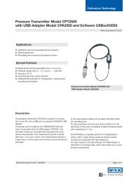
1. "On/Off" Power Switch 10. Static Ports (x2) + Static or A.O.A Ports (x2)<br />
1A.Push button (to start with battery power)11. Pitot Ports (x4)<br />
2. Fuse 12. Keyboard<br />
3. Power Connector 13. LCD Display<br />
4. Pitot Vent needle Valve 14. Encoding Altimeter Connection (Optional)<br />
5. Cross bleed needle Valve 15. External vacuum supply port<br />
6. Labyrinth to ambient 16. External pressure supply port<br />
7. Serial Port 17. Compact Flash card<br />
8. Hand Held Remote Terminal 18. Ground Connection<br />
9. Water condensate extraction button<br />
FIG. 1 - AIR DATA TEST SET P/N <strong>MPS</strong> <strong>35C</strong> FRONT PANEL<br />
Vers. 0208 D.Marchiori s.r.l. 7
FIG. 2 - LAYOUT OF HHRCU KEYBOARD AND DISPLAY<br />
CM/PP/<strong>MPS</strong><strong>35C</strong>/0208<br />
Vers. 0208 D.Marchiori s.r.l. 8
SECTION 1 - <strong>MPS</strong> <strong>35C</strong> CONTROL KEYS<br />
1.1 GENERAL DESCRIPTION<br />
CM/PP/<strong>MPS</strong><strong>35C</strong>/0208<br />
The D. Marchiori, DMA, <strong>MPS</strong> <strong>35C</strong> is an <strong>Air</strong> <strong>Data</strong> <strong>Test</strong> solution for troubleshooting and<br />
certification of aircraft pitot-static systems with RVSM accuracy requirements. It provides the<br />
operator with the ability to test the aircraft and to generate and store re-test envelopes required<br />
for air data testing of all modern commercial and various military fixed and rotary wing aircraft.<br />
Additional to normal pitot-static testers it also has a third delta P read and control channel for<br />
the testing of Angle of attack Smart Probes<br />
The <strong>MPS</strong> <strong>35C</strong> utilises precision hi-technology resonant element and silicon bridge pressure<br />
transducers to achieve maximum accuracy.<br />
An internal rechargeable battery providing more than 4 hours operation is included.<br />
The <strong>MPS</strong> <strong>35C</strong> is simple and fast to use. The operator interface is easy to learn and understand<br />
by both experts and first time users. All testing and troubleshooting with the <strong>MPS</strong> <strong>35C</strong> is<br />
performed via an intuitively arranged colour-coded keypad on the front panel. All test information<br />
is displayed on a large, easy to read LCD display or alternatively a multifunction remote hand<br />
controller.<br />
Commanded and measured test values are simultaneously displayed at all times.<br />
The <strong>MPS</strong> <strong>35C</strong> incorporates the DMA on-demand pumps system utilised on the series of larger<br />
<strong>MPS</strong> air data test sets. The internal vacuum and pressure sources run only if required, to insure<br />
longer pump life.<br />
The <strong>MPS</strong> <strong>35C</strong> comes equipped with built-in protection to safeguard the test set and the UUT or<br />
instruments under test, no longer the old problem of damaged instruments or air data test sets.<br />
Both the test set and instruments under test are protected by important key <strong>MPS</strong> <strong>35C</strong> design<br />
features. The pressure condition of Ps greater than Pt (negative airspeed / Qc ) is prevented in<br />
both manual and automatic operation. The Unit Under <strong>Test</strong> (UUT) is safely isolated in the event<br />
of any power loss.<br />
The <strong>MPS</strong> <strong>35C</strong> is designed to reject any commanded values which exceed pre-programmed<br />
limits. Limits values are password protected.<br />
To facilitate leak testing and troubleshooting, the <strong>MPS</strong> is supplied with multiple ports, located on<br />
the front panel which can be isolated individually, and can be controlled either by the Hand Held<br />
Remote control Unit (HHRCU) or the front panel keyboard. Different static and pitot pressures<br />
can also be established in these lines and applied as required.<br />
For Angle of Attack testing these ports are reconfigured to allow testing of Ps1-Ps2<br />
The <strong>MPS</strong> <strong>35C</strong> allows the User to carry out simple to perform in-house calibrations. Using a<br />
transfer calibration standard (for example the D. Marchiori's own product the PAMB 6 or PAMB<br />
7), the <strong>MPS</strong> <strong>35C</strong> can be calibrated in typically less than 20 minutes after a sufficient warm up<br />
period.<br />
Calibration is performed by software adjustment only. No mechanical adjustments are required<br />
to the ADTS. Calibration factors are password protected.<br />
<strong>MPS</strong> <strong>35C</strong> optionally can be equipped with an encoding altimeter reading function, and with<br />
removable compact flash card memory to store and manage test results.<br />
Vers. 0208 D.Marchiori s.r.l. 9
1.2 PHYSICAL DESCRIPTION<br />
CM/PP/<strong>MPS</strong><strong>35C</strong>/0208<br />
The <strong>MPS</strong> <strong>35C</strong> main constituents feature of a power supply, digital control cards, pressure<br />
sensors, and pneumatic control components. All are packaged within a case of lightweight<br />
HDPE material.<br />
The front panel provides operating controls and displays, pressure fittings and electrical<br />
connectors for external control.<br />
A picture of the <strong>MPS</strong> <strong>35C</strong> console is displayed in Fig.: 1.<br />
1.3 KEYPAD KEYS<br />
Control and data entry of the <strong>MPS</strong> <strong>35C</strong> is via a keypad on the front panel (Fig. 2). Five rows of<br />
keys provide access to all of the <strong>MPS</strong> <strong>35C</strong>’s control and operational functions. Keys are colour<br />
coded for ease of use. A telephone format 0 to 9 keypad is included for entry of target values.<br />
First Row keys:<br />
HALT: when pressed the <strong>MPS</strong> <strong>35C</strong> remains in the CONTROL MODE but adopts automatically,<br />
as the COMMANDED (controlled) air data parameters, the values which are present at the<br />
instant the HALT key has been pressed.<br />
The HALT key can be considered as a “panic button” to be used when it is necessary to hold the<br />
parameters at the current values.<br />
LIMITS-UNITS / EPR is used to enter the LIMITS/UNITS MENU or EPR MENU. These menus<br />
are for viewing or changing the default limit values and units as they are pre-set from the<br />
factory. To return to CONTROL MODE of operation, the LIMITS-UNITS key must be pressed a<br />
second time. Refer to Section 6.<br />
The EPR key, in association with the SHIFT key, activates the E.P.R. function. Refer to Section<br />
12.12.<br />
EXEC / PROG: This key is used to run a particular pre-defined test profile: the <strong>MPS</strong> <strong>35C</strong> can<br />
store 30 different test profiles, each one with 26 different test points; the target values of<br />
Altitude, <strong>Air</strong>speed, Altitude Rate and <strong>Air</strong>speed Rate can be entered and stored into each of the<br />
30 test profiles. Refer to Section 14.<br />
The PROG key, in association with the SHIFT key allows the entering of program profile points<br />
MEM / CAL:The MEM key is used to memorize new parameters; the CAL is used to tare off any<br />
pitot sensor minor errors to improve its performance at low airspeeds.<br />
MULTIPLE ISOLATOR / ENC is used to select which of the optional multiple isolated Ps and Pt<br />
ports are to be opened, or closed. Refer to Section 9.<br />
The ENC key, in association with the SHIFT key, activates the Encoding Altimeter option. Refer<br />
to Refer to Section 12.13.<br />
SHIFT has the same function as a shift key on a computer keyboard. It is used together with<br />
other keys to command alternate key functions (e.g. [SHIFT] + [LIMITS-UNITS]] to activate<br />
E.P.R.), or [SHIFT] + [0] to activate the “Fine Tuning”) .<br />
A summary of SHIFT key operations is shown in Section 12.15.<br />
BACKSPACE : this key is used to delete the last entered digit if a mistake is made in entering a<br />
command.<br />
Vers. 0208 D.Marchiori s.r.l. 10
Second Row Keys, left side:<br />
CM/PP/<strong>MPS</strong><strong>35C</strong>/0208<br />
MEAS: the MEAS or “MEASUREMENT” is used to stop the operation of the pressure control<br />
system leaving only the pressure measuring system active. This function is used to achieve<br />
extra accuracy for measuring pressures statically to avoid any controller induced effects.<br />
The CNTRL , CONTROL key is used to return the <strong>MPS</strong> <strong>35C</strong> to the CONTROL MODE.<br />
VENT: is used to vent the pressure in the static and pitot lines to ambient pressure. This<br />
function allows for the safe disconnection of test lines from the aircraft or UUT at the end of<br />
testing. The CNTRL key is used to restore the <strong>MPS</strong> <strong>35C</strong> to CONTROL MODE, after the Vent<br />
function has been selected.<br />
LEAK: is used to automatically perform the leak test using the built in timer/stopwatch function<br />
of the <strong>MPS</strong> <strong>35C</strong>. The CNTRL key is used to restore the test set to the CONTROL MODE of<br />
operation, after LEAK key is used.<br />
Second and Third Row Keys, right side:<br />
The UP (DOWN) triangular keys ▲ (or ▼) are used:<br />
- to increase (or decrease) the different parameters (ALTITUDE, AIRSPEED, RATE OF<br />
CHANGE, PRESSURES) by a selected digit value;<br />
- in the UNITS MENU, for the changing of parameters units;<br />
- in programmed profiles to select the next (or previous) test point;<br />
- in the DISPLAY MENU to set the display (brightness and contrast).<br />
The same keys are also used in some other specified operations.<br />
Third Row Keys, left:<br />
CNTRL: is used to initiate or to return the equipment to CONTROL MODE.<br />
NOTE<br />
CNTRL is the most frequently used key in the general operation of the <strong>MPS</strong><br />
35 C.<br />
Qc/Pitot: is used to toggle switch between differential pressure (Qc) and pitot pressure.<br />
ALRt/ASPRt: is a toggle switch used to select either ALTITUDE RATE, AIRSPEED RATE,<br />
STATIC PRESSURE RATE or PITOT PRESSURE RATE.<br />
The default AIRSPEED RATE value is 300 knots/min. The default ALTITUDE RATE is 3000<br />
Ft/min.<br />
Fourth and Fifth Row Keys, left:<br />
The DIGIT key is used to select different digits on each <strong>Air</strong> <strong>Data</strong> Parameter.<br />
The ← or → keys are used to navigate around the display in the CONTROL, LIMITS and UNITS<br />
menus. These keys are used to move the cursor “>” to the desired input zone for entry of a<br />
specific value using the numeric keypad.<br />
The 000 key is used to enter thousands into a demand value, if allowed by the programmed<br />
limits.<br />
Vers. 0208 D.Marchiori s.r.l. 11
CM/PP/<strong>MPS</strong><strong>35C</strong>/0208<br />
The ENTER is used to input desired data the <strong>MPS</strong> <strong>35C</strong>. The operation is the same as an “Enter”<br />
key on a computer keyboard.<br />
Numerical keypad, center:<br />
This keypad is a standard telephone layout layout ten-keys keypad. The numerical keys (0–9)<br />
are used to enter any desired value of the various controlled parameters. After keying in number<br />
values, the ENTER key is always required to enter, confirm, the completed number into the<br />
system.<br />
NOTE<br />
For some optional operations, number keys may be used in combination<br />
with the SHIFT key, to access additional functions.<br />
The decimal point key (.) is used to input decimal points when required (e.g. airspeed).<br />
The minus key (–) is used to set negative altitudes (e.g. when static pressure is higher than the<br />
ambient).<br />
Vers. 0208 D.Marchiori s.r.l. 12
SECTION 2 - OPERATIONAL MODES, MENUS AND DISPLAYS<br />
NOTE<br />
The <strong>MPS</strong> <strong>35C</strong> has multiple operational modes, menus and displays. Modes<br />
are defined by the operational characteristics that are in use during<br />
operations in the named mode. Menus refer to operations and information<br />
that are accessible and changeable on the displayed LCD screen. Displays<br />
refer to data that is displayed in a read-only format on the screen. Display<br />
screens are read only; they do not allow parameters to be entered or<br />
changed.<br />
2.1 CONTROL MODE<br />
CM/PP/<strong>MPS</strong><strong>35C</strong>/0208<br />
This is the primary mode for control of the <strong>MPS</strong> <strong>35C</strong>. <strong>Air</strong> data parameter entry and all the<br />
operational/control functions are all performed in this mode. The access to CONTROL MODE is<br />
through the CONTROL MENU.<br />
Entry to the CONTROL MODE is by pressing the CNTRL key.<br />
Return to CONTROL MODE at any time from any other mode of operation is by pressing the<br />
CNTRL key.<br />
2.1.1 CONTROL MODE MENU<br />
The CONTROL MODE MENU is displayed when the <strong>MPS</strong> <strong>35C</strong> is in CONTROL MODE.<br />
SIMULATED (ACTUAL) values are displayed on the “SIM” line of the display while the<br />
COMMANDED (DESIRED) values are displayed on the “CMD” line of the display.<br />
<strong>Air</strong> data parameters will be displayed on the upper two lines of the LCD screen (upper “CMD”<br />
and “SIM” lines) and the equivalent pressure parameters will be displayed on the lower two lines<br />
of the screen (lower “CMD” and “SIM” lines).<br />
2.2 MEASURE MODE<br />
MEASURE MODE is used to stop controlling the pressures so that only the pressure measuring<br />
system is activated: all control functions are disabled and only sensor measurement functions<br />
are active. The unit under test (UUT) is now completely isolated from the pressure generator<br />
and a precise measurement can be obtained when the line pressures in the system under test<br />
are stabilized. Whenever a precision measurement is required, in particular when the large<br />
volumes are involved, the MEAS function should be used. MEASUREMENT MODE can be<br />
accessed from all menus.<br />
Entry to the MEASUREMENT MODE is by pressing the MEAS key.<br />
Return to CONTROL MODE is by pressing the CNTRL key or to other modes by pressing the<br />
required mode entry key.<br />
2.2.1 MEASURE MODE MENU<br />
The MEASURE MODE MENU is displayed when the <strong>MPS</strong> <strong>35C</strong> is in MEASURE MODE. When<br />
the MEASURE MODE MENU is displayed, the word “MEAS” will appear in the lower right-hand<br />
corner of the LCD screen.<br />
Vers. 0208 D.Marchiori s.r.l. 13
2.3 VENT MODE<br />
CM/PP/<strong>MPS</strong><strong>35C</strong>/0208<br />
This mode is used to vent the pitot and static ports of the <strong>MPS</strong> <strong>35C</strong> to the current ambient, or<br />
ground, pressure condition. The VENT MODE is operated by pressing the VENT key. The <strong>MPS</strong><br />
<strong>35C</strong> then automatically initiates a 3000 feet/min. descent (or ascent) rate to reach initially an<br />
altitude 2000 feet higher than local Field Elevation.<br />
When the <strong>MPS</strong> <strong>35C</strong> reaches this 2000 ft value, it then pauses the venting while going away to<br />
measure the actual current ambient pressure value and then continues the venting bringing the<br />
Ps and Pt ports to that safe pressure. This ensures the pressures inside the hoses are identical<br />
to the ambient pressure and the aircraft or system under test can safely be disconnected<br />
In the <strong>MPS</strong> <strong>35C</strong> it is possible to set the field/location value, and then to read the QNH.<br />
When the instrument is shipped a value of zero feet will be entered as the Field Elevation. To<br />
set a different value of the Field Elevation, it is necessary to go into the FINE TUNING MODE,<br />
instructions are given in the Calibration and Adjustments <strong>Manual</strong>.<br />
When the conditions are safe to disconnect the hoses, the legend:<br />
“AMBIENT PRESSURE REACHED” is displayed.<br />
Entry to the VENT MODE is by pressing the VENT key.<br />
From VENT MODE, only the CONTROL MODE can be accessed.<br />
To return to CONTROL MODE press the CNTRL key.<br />
2.3.1 VENT MODE MENU<br />
The VENT MODE MENU is displayed when the <strong>MPS</strong> <strong>35C</strong> is in the VENT MODE. When the<br />
VENT MODE MENU is displayed, the word “VENT” will appear in the lower right-hand corner of<br />
the LCD screen.<br />
2.4 LEAK MODE<br />
The LEAK MODE initiates the automatic leak test and stopwatch measurement feature of the<br />
<strong>MPS</strong> <strong>35C</strong>. LEAK MODE access is through the LEAK MENU.<br />
Entry to the LEAK MODE is by pressing the LEAK key.<br />
Return to CONTROL MODE is by pressing the CNTRL key.<br />
2.4.1 LEAK MODE DISPLAY<br />
The LEAK MODE DISPLAY is shown when the <strong>MPS</strong> <strong>35C</strong> is in LEAK MODE. When the LEAK<br />
MODE is in operation, ALITUDE RATE (“AltRate”) and AIRSPEED RATE (“Asp Rate”) plus<br />
elapsed time in seconds will be displayed on the upper two lines of the LCD screen. The legend<br />
“LEAK” appears in the lower right-hand corner of the LCD screen.<br />
2.5 LIMITS MODE<br />
The LIMITS MODE allows the operator to change the actual limits of all the functions. Access to<br />
the LIMITS MODE is via the LIMITS MENU.<br />
The LIMITS key is used to enter LIMITS MENU. To return to CONTROL MODE or any other<br />
mode, the LIMITS key must be pressed a second time.<br />
2.5.1 LIMITS MODE MENU<br />
The LIMITS MODE MENU is displayed when the <strong>MPS</strong> <strong>35C</strong> is in LIMITS MODE. When the<br />
LIMITS MODE MENU is displayed, two vertical columns of parameters will be shown, starting<br />
with the parameter “AlMx >”. Refer to Section 6.<br />
Vers. 0208 D.Marchiori s.r.l. 14
SECTION 3 - START UP PROCEDURE<br />
WARNING<br />
Follow all the safety procedures in the aircraft maintenance manual.<br />
IMPORTANT NOTE FOR THE FIRST TIME USE IN A GIVEN LOCATION<br />
It is recommended that the operator enters the Field Elevation of the<br />
location where the <strong>MPS</strong> <strong>35C</strong> is being to be used, to permanently save this<br />
value in the internal memory this value, It is very important during the<br />
VENTING MODE of operation: when venting to the ambient pressure the<br />
<strong>MPS</strong> <strong>35C</strong> will measure the ambient pressure when at a value that is 2000<br />
feet higher than the Field Elevation.<br />
To set and permanently memorize the correct Field Elevation value, it is<br />
necessary to enter into the FINE TUNING MODE .<strong>Instructions</strong> are given in<br />
the Calibration and Adjustments <strong>Manual</strong>. If at the first start-up, the Venting<br />
<strong>Operation</strong> it is not performed fully, press CNTRL key to enter the<br />
OPERATIVE MENU and proceed to set and memorize the Field Elevation<br />
Altitude as per Calibration and Adjustment <strong>Manual</strong>.<br />
Place the <strong>MPS</strong> <strong>35C</strong> in the face-up position.<br />
Connect the power cord to the military style connector on the front panel.<br />
CM/PP/<strong>MPS</strong><strong>35C</strong>/0208<br />
Leave the static and pitot lines disconnected. Static and pitot lines should be connected only<br />
after start-up is completed.<br />
Turn the power toggle switch to “ON”.<br />
WARNING<br />
- If <strong>MPS</strong> <strong>35C</strong> is not power connected or the ac power is not available, it can<br />
operate with the internal battery power. In this situation, after turning on the<br />
toggle switch to “ON” (Fig. 1-1), additionally press the green push button<br />
(Fig. 1-1A).<br />
- The battery is in charge only when the <strong>MPS</strong> <strong>35C</strong> is power connected and<br />
the switch (Fig. 1-1) is in up or down position.<br />
The <strong>MPS</strong> <strong>35C</strong> display will first illuminate; then show the serial number of the unit, total operation<br />
time and last calibration date.<br />
When the start-up and self-test is completed, there are three possibilities:<br />
• A. If an altitude higher than 8,000ft is sensed in the static line, the <strong>MPS</strong> <strong>35C</strong> automatically<br />
continues in the control mode and allows the Operator to either continue working at that<br />
altitude, or to press the VENT key.<br />
• B. If the altitude is lower than 8,000ft <strong>MPS</strong> <strong>35C</strong> will automatically initiate a 3000 feet/min.<br />
descent rate to reach initially an altitude 2000 feet higher than local Field Elevation. When<br />
the <strong>MPS</strong> <strong>35C</strong> reaches this 2000 ft value, it then pauses the venting while going away to<br />
measure the actual current ambient pressure value and then continues the venting bringing<br />
the Ps and Pt ports to that safe pressure.<br />
• C If the altitude is lower than 2000 feet plus local Field Elevation value, the equipment will<br />
start a VALVES TEST, which is shown in the display right lower corner with the word “WAIT“.<br />
Once this valves test has been completed the equipment will then read the ambient pressure<br />
Vers. 0208 D.Marchiori s.r.l. 15
CM/PP/<strong>MPS</strong><strong>35C</strong>/0208<br />
and will vent the system to this value. The valves test procedure can be terminated at any<br />
time by pressing the HALT key.<br />
To vent the <strong>MPS</strong> <strong>35C</strong> and zero the pitot line, press the VENT key. Wait until "AMBIENT<br />
PRESSURE REACHED" is displayed, press CNTRL to then initiate in CONTROL MODE.<br />
NOTE<br />
For maximum accuracy of AIRSPEED measurements at low airspeed,<br />
relate to Section 7.<br />
Vers. 0208 D.Marchiori s.r.l. 16
SECTION 4 - ENTERING AIR DATA TEST PARAMETERS INFORMATION<br />
CM/PP/<strong>MPS</strong><strong>35C</strong>/0208<br />
<strong>Air</strong> <strong>Data</strong> Parameters (ALTITUDE, AIRSPEED and RATE) can be commanded (entered) in two<br />
modes:<br />
1. By operating the <strong>MPS</strong> <strong>35C</strong> in the CONTROL MODE.<br />
When the CONTROL MODE is active the <strong>MPS</strong> <strong>35C</strong> starts to change the<br />
pressures as soon as new air data values are entered.<br />
2. By operating the <strong>MPS</strong> <strong>35C</strong> in MEASURE MODE.<br />
If it is desired that the <strong>MPS</strong> <strong>35C</strong> starts to change pressures only after all the new air data<br />
parameters have been entered, it is necessary to go to the MEASURE (or HALT MODE),<br />
enter the new target values and then return to the CONTROL MODE by pressing the<br />
CNTRL key.<br />
New target values can also be entered by using the ▲ (to increase) or ▼ (to decrease) triangle<br />
keys.<br />
NOTE<br />
If a value of ALTITUDE or AIRSPEED or ALTITUDE RATE greater than the<br />
actual limits (the values programmed in the LIMITS MENU ) is selected, the<br />
value will not be accepted and the limit value automatically will be entered<br />
instead. As an example, if an airspeed value of 999 knots is entered while<br />
the limit value is set at 400 knots, 400 knots will be the commanded value<br />
into the equipment, when the ENTER key is pressed.<br />
4.1 METHOD 1, ENTERING OF SPECIFIC COMMAND VALUES<br />
The <strong>MPS</strong> <strong>35C</strong> is programmed by entering COMMAND (“CMD”) line values for ALTITUDE,<br />
AIRSPEED and RATE OF CHANGE in the CONTROL MODE. A COMMAND value may be<br />
entered in any of the COMMAND LINE input zones after selecting ALTITUDE, AIRSPEED or<br />
RATE. To enter a COMMAND value, the cursor (>) must be in the desired input zone. Arrow<br />
keys (← or →) are used to navigate the cursor (>) to the desired input zone. The arrow keys can<br />
be used at any time when the <strong>MPS</strong> <strong>35C</strong> is in CONTROL, HALT or MEASURE MODE.<br />
These arrow keys (← or →) are used to move among each of the three parameter columns<br />
(ALTITUDE, AIRSPEED and RATE) and also to move up and down on the three display screen<br />
parameter columns (the ALTITUDE column, AIRSPEED column and RATE column).<br />
By pressing the right or left arrow keys the cursor (>) navigates among the three parameter<br />
columns on the upper air data COMMAND (“CMD”) LINE (ALTITUDE, AIRSPEED and RATE)<br />
and the lower COMMAND LINE for the pressure engineering units.<br />
4.1.1 ALTITUDE COMMAND<br />
To enter an altitude, scroll the cursor to “ ALTITUDE “ in the COMMAND (“CMD”) LINE input<br />
zone. Enter the target value by digitizing it on the keypad (20000 feet, for example). If an<br />
incorrect number is selected, the BACKSPACE key can be used to erase the incorrect<br />
digit. After the number is erased with the BACKSPACE key, the correct number can be entered.<br />
When the correct ALTITUDE has been digitized, press the ENTER key to activate the new<br />
command value.<br />
4.1.2 AIRSPEED COMMAND<br />
Scroll the cursor to “AIRSPEED “ in the COMMAND (“CMD”) LINE input zone. Enter the target<br />
value by digitizing it on the keypad (400 knots for example). If an incorrect number is selected,<br />
the BACKSPACE key can be used to erase the incorrect digit. When the correct AIRSPEED has<br />
been digitized, press the ENTER key to activate the new command value.<br />
Vers. 0208 D.Marchiori s.r.l. 17
4.1.3 ALTITUDE RATE COMMAND (RATE OF CHANGE)<br />
CM/PP/<strong>MPS</strong><strong>35C</strong>/0208<br />
Scroll the cursor to “ RATE “ in the COMMAND (“CMD”) LINE input zone. Enter the target value<br />
by digitizing it on the keypad (3000 ft/min. for example). If an incorrect number is selected, the<br />
BACKSPACE key can be used to erase the incorrect digit. When the correct RATE has been<br />
digitized, press the ENTER key to activate the new command value.<br />
The <strong>MPS</strong> <strong>35C</strong> will begin to achieve the entered COMMAND LINE value immediately. When it is<br />
preferable that the <strong>MPS</strong> <strong>35C</strong> should start to reach the values only after all the new parameters<br />
have been properly entered, then enter the commanded parameters in the MEASURE MODE; in<br />
this case it is also then necessary to re-enter into the CONTROL MODE by pressing the CNTRL<br />
key and all the new values will then be activated.<br />
ALTITUDE AIRSPEED RATE<br />
SIM 24519 192.8 3000 SIM<br />
CMD 30000 200.0 3000 CMD<br />
SIM 11.338 1.817 0,465 SIM<br />
CMD 8.885 1.959 0,465 CMD<br />
Pst Qc/Ptot MACH<br />
FIG. 3 - EXAMPLE OF DISPLAY LAYOUT IN CONTROL MODE<br />
Vers. 0208 D.Marchiori s.r.l. 18
4.2 METHOD 2-VALUES COMMAND WITH DIGIT CHANGE FUNCTION<br />
CM/PP/<strong>MPS</strong><strong>35C</strong>/0208<br />
<strong>Air</strong> <strong>Data</strong> Parameter values can also be modified by using the “Digit" function. As with the direct<br />
value entry method above, the “Digit" function can be used in CONTROL or in MEASURE<br />
MODE.<br />
The “Digit" function provides a quick way to change an <strong>Air</strong> <strong>Data</strong> Parameter.<br />
The UP (DOWN) triangle keys ▲ (or ▼) and DIGIT key are used with the “Digit" function. Once<br />
selected with ← or → keys, each <strong>Air</strong> <strong>Data</strong> Parameter has one digit flashing.<br />
Use ▲ (or ▼) keys to increase or decrease the flashing digit by 1.<br />
Use DIGIT key to move to the left (or SHIFT DIGIT keys to move to the right) to change the<br />
parameter digit that is to be changed.<br />
For example: Altitude parameter is selected, and the set value is 6543:<br />
Ø if 6 is the flashing digit, pushing ▲ (or ▼) keys the set Altitude can be modified to 7543,<br />
8543.... (increasing), or to 5543, 4543... (decreasing);<br />
Ø use DIGIT key (or SHIFT DIGIT keys) until the another digit starts flashing, for example the<br />
last one (3); now pushing ▲ (or ▼) keys the set Altitude can be modified to 6544, 6545<br />
increasing), or to 6542, 6541 (decreasing).<br />
The “Digit” function can increase (or decrease) the value of a parameter in units, tens or<br />
hundreds 1,10,100 … depending on the flashing digit.<br />
As described, using the “Digit" function, once an <strong>Air</strong> data parameter is selected, any digit can be<br />
modified separately from the others.<br />
A continuous increase (decrease) of the parameter is obtained when ▲ (or ▼) keys are<br />
maintained pressed.<br />
4.3 ACOUSTIC ALARM FUNCTION<br />
When the SIM (Actual) values are almost at the CMD (Desired) values (around 10 feet and 1<br />
knot) an acoustic alarm will start sounding (beep-beep) to warn the operator that the <strong>MPS</strong> <strong>35C</strong><br />
is approaching the target values.<br />
If the operator does not want the acoustic signal, the function can be deactivated by the key<br />
(SHIFT 0) = F0, followed by password. Refer to Section 12.14.<br />
Vers. 0208 D.Marchiori s.r.l. 19
SECTION 5 - ADVANCED OPERATIONS<br />
5.1 DIFFERENT RATE COMMANDS<br />
CM/PP/<strong>MPS</strong><strong>35C</strong>/0208<br />
The ALRT/ASPRT key is used to select the different rates.<br />
Below the word “RATE“ a letter in front of the numerical value will indicate the active function:<br />
i.e. the letter “A“ will indicate to the operator that the rate controlled is the ALTITUDE RATE. The<br />
Altitude Rate is the default.<br />
By pressing the ALRT/ASPRT key, the letter “S” will appear in front of the value shown on the<br />
display meaning that the the equipment is now controlling the AIRSPEED RATE.<br />
Note that the equipment has an AIRSPEED RATE default value of 300 Kts/min.<br />
By pressing the key code SHIFT ● 5 6 7 8, the rates are now able to be entered in pressure<br />
units (STATIC and DIFFERENTIAL PRESSURE RATES instead of ALTITUDE and AIRSPEED<br />
RATES). Press again SHIFT ● 5 6 7 8 keys to return to engineering units (ALTITUDE and<br />
AIRSPEED RATES).<br />
Summarizing, by pressing the ALRT/ASPRT key, the operator can select alternatively the<br />
Altitude Rate or the <strong>Air</strong>speed Rate, and the Static Pressure Rate or the Differential Pressure<br />
Rate, in the engineering unit which has already been selected: the active parameter will always<br />
be shown in front of the word “RATE” on the screen (SIM line).<br />
For safety reasons, when passing from engineering units to pressure units.,<br />
the <strong>MPS</strong> <strong>35C</strong> remains in the CONTROL MODE, but adopts automatically,<br />
as the COMMANDED (controlled) air data parameters, the equivalent<br />
values of altitude and airspeed which are present at the instant the<br />
SHIFT ● 5 6 7 8 keys have been pressed.<br />
CAUTION<br />
If <strong>MPS</strong> <strong>35C</strong> is switched off, then when it is next powered up, the default<br />
rates will be ALTITUDE and AIRSPEED RATES.<br />
To permanently store pressure units (STATIC and DIFFERENTIAL<br />
PRESSURE RATES) instead of ALTITUDE and AIRSPEED RATES as<br />
“default rates” in the <strong>MPS</strong> <strong>35C</strong> consult the <strong>MPS</strong> <strong>35C</strong> Calibration and<br />
Adjustment <strong>Manual</strong> where instructions to achieve this modification are<br />
given.<br />
5.2 PRESSURE VALUES COMMAND IN DIRECT ENGINEERING UNITS<br />
If desired, instead of aeronautical units, direct pressure units can be used to enter pitot or static<br />
pressure values or differential pressure values (pitot pressure – static pressure). For this<br />
operation, the lower COMMAND (“CMD”) LINE input zones are used. The commanded default<br />
pressure value is displayed in inches of Mercury or inHg.<br />
5.2.1 ALTITUDE COMMAND USING DIRECT PRESSURE VALUES<br />
Scroll the cursor to the lower COMMAND LINE input zone for Pst (Static Pressure). The desired<br />
pressure value can be entered by using a direct number value or by using the ▲ (or ▼) keys.<br />
Enter the desired specific pressure value by digitising it on the keypad (18.00 inHg for example).<br />
If an incorrect number is input, the BACKSPACE key can be used to erase the incorrect digit.<br />
After the incorrect number has been erased with the BACKSPACE key, the correct number can<br />
be entered. When the correct Ps is entered, press the ENTER key to confirm the new value.<br />
Vers. 0208 D.Marchiori s.r.l. 20
5.2.2 AIRSPEED COMMAND USING DIFFERENTIAL PRESSURE VALUES<br />
CM/PP/<strong>MPS</strong><strong>35C</strong>/0208<br />
(Qc = Differential Pressure)<br />
Scroll the arrow prompt to the COMMAND (“CMD”) LINE input zone for Qc (Differential<br />
Pressure). The desired pressure value can be entered by using a direct number value or by<br />
using the ▲ (or ▼) keys.<br />
Enter the desired specific pressure value by digitising it on the keypad (10,55 inHg for example).<br />
If an incorrect number is entered, the BACKSPACE key can be used to erase the incorrect digit.<br />
After the incorrect number has been erased with the BACKSPACE key, the correct number can<br />
be entered. When the correct Qc is entered, press the ENTER key to confirm the new value.<br />
5.3 SPECIFIC PITOT PRESSURE VALUE COMMAND<br />
To enter a specific pitot pressure, use the Qc/Ptot key (“Qc” for differential pressure<br />
and “Ptot” for Pitot pressure. [= Static pressure + Differential Pressure]).<br />
Qc/Ptot key is used to toggle between the normal default setting (Qc) Differential Pressure and<br />
the Pitot total Pressure (Ptot).<br />
The value displayed in the COMMAND (“CMD”) LINE input zone will toggle between<br />
DIFFERENTIAL PRESSURE (Qc) and PITOT TOTAL PRESSURE (Ptot).<br />
The Qc/Ptot key should be used to toggle from one to the other, on the screen the<br />
DIFFERENTIAL PRESSURE value or the PITOT PRESSURE (Ptot) one will appear.<br />
Enter the desired PITOT PRESSURE (Ptot) or the DIFFERENTIAL PRESSURE ( Qc) value in<br />
the input zone and press the ENTER key to confirm the new value.<br />
5.4 MACH NUMBER<br />
MACH NUMBER can be entered as a control parameter in place of an AIRSPEED value. To<br />
enter a MACH NUMBER select the MACH NUMBER value in the COMMAND MENU. After<br />
inputting the desired MACH NUMBER, press ENTER. The AIRSPEED corresponding to this<br />
Mach number, at the set altitude, will now be shown in the CMD line of the AIRSPEED column.<br />
Note that MACH NUMBERS are altitude dependent.<br />
If another Mach Number at a different altitude has to be entered, the same procedure must be<br />
followed. This is because the Mach number is only calculated for a particular ALTITUDE and set<br />
as the target AIRSPEED for that ALTITUDE.<br />
MACH NUMBER must be entered when the Altitude Rate is not equal to 0.<br />
5.5 LEAK TEST MODE OPERATION<br />
The LEAK TEST MODE operation allows the operator to perform a leak test of the static and<br />
pitot lines by using the internal stopwatch. Leak rates for pitot and static lines are calculated<br />
every second and are automatically shown in ft/min. and kt/min. in the LEAK MODE DISPLAY<br />
screen.<br />
Warning<br />
It is recommended that an initial leak test is always carried out at low<br />
altitude and low airspeed values in case there are dramatically large leaks<br />
which could cause problems if not corrected.<br />
Select the leak test function by pressing the LEAK key. The LEAK DISPLAY will appear. The<br />
LEAK DISPLAY will begin counting the elapsed seconds and displaying the leak rates for the<br />
pitot and static lines, below the Alt + Asp rates.<br />
Vers. 0208 D.Marchiori s.r.l. 21
ALTITUDE AIRSPEED RATE<br />
SIM sec AltRate AspRate SIM<br />
CMD 170 -6 0.4 CMD<br />
SIM 20.593 0.504 0.189 SIM<br />
CMD 28.577 0.481 LEAK CMD<br />
Pst Qc/Ptot MACH<br />
WARNING<br />
After the LEAK key has been pressed, in order to to get the best LEAK<br />
measurement ,it is necessary to wait until the values in the LEAK DISPLAY<br />
are relatively stable.<br />
Typically this happens after about one minute.<br />
When the leak values are stabilised, press the LEAK key once more to<br />
reset the clock to restart a further leak test.<br />
To return to the previous menu, press the CNTRL key.<br />
5.6 MEASURE (MEAS) MODE<br />
CM/PP/<strong>MPS</strong><strong>35C</strong>/0208<br />
The MEAS key commands the <strong>MPS</strong> <strong>35C</strong> to the MEASUREMENT MODE of operation. In this<br />
mode the <strong>MPS</strong> <strong>35C</strong> deactivates the pressure control circuit and only the pressure measuring<br />
system remains activated. The unit under test is completely isolated from the pressure<br />
generator circuits of the <strong>MPS</strong> <strong>35C</strong>. A very precise measurement can be taken once the<br />
pressures in the lines under test are stable. This mode should be used whenever very precise<br />
measurement is required.<br />
The MEASURE MODE function should always be used when very large test volumes are<br />
involved in the measurement, such as with an older aircraft. To return to CONTROL MODE,<br />
press the CNTRL key.<br />
CAUTION<br />
When the <strong>MPS</strong> <strong>35C</strong> is in MEASURE MODE or in LEAK MODE of operation<br />
and a leak higher then a prefixed value (i. e. 3.000 feet/min.) is in progress,<br />
the equipment will revert automatically to the CONTROL MODE as a<br />
protection of the UUT.<br />
To permanently store a different value as default in the <strong>MPS</strong> <strong>35C</strong> memory,<br />
consult the <strong>MPS</strong> <strong>35C</strong> Calibration and Adjustment <strong>Manual</strong> where<br />
instructions to achieve this modification are given.<br />
Vers. 0208 D.Marchiori s.r.l. 22
SECTION 6 - PRESET LIMITS AND ENGINEERING UNITS CHANGE<br />
6.1 CHANGING PRESET LIMITS<br />
CAUTION<br />
Limits are pre-set at the factory to handle most standard test conditions and<br />
to protect most aircraft instrumentation. The operator should use extreme<br />
care and caution when setting limits different to the factory default values.<br />
Damage to the aircraft or unit under test could occur, if caution is not<br />
observed.<br />
CM/PP/<strong>MPS</strong><strong>35C</strong>/0208<br />
To enter the LIMITS MENU from the CONTROL MENU use the LIMITS key.<br />
To exit the LIMITS MENU press again the LIMITS key. Arrow keys (▲ ▼) are used to navigate<br />
the enter cursor (>) to the desired input zone.<br />
CAUTION<br />
The LIMIT MENU allows the operator to change either the operative limits<br />
and/or the Engineering Units of <strong>MPS</strong> <strong>35C</strong>. The first three rows of the menu<br />
are dedicated to the change of operational limits, the last one to modify the<br />
Engineering Units.<br />
Limit values can be changed either permanently or for the duration of one test cycle. The<br />
operator should consider carefully which requirement best suites the needs of all users.<br />
To change the limits or the step values, scroll the cursor to the front of the value of the limit that<br />
is to be changed.<br />
To change the value, enter the new value and press the ENTER key.<br />
The pre-set limits are given in the LIMITS MENU as follows:<br />
• ALMx is the maximum allowed altitude.<br />
• ALMi is the minimum allowed altitude.<br />
• ASMx is the maximum allowed airspeed.<br />
• MaMx is the maximum allowed Mach number.<br />
• AltRateMx is the maximum allowed altitude/rate.<br />
NOTE<br />
If different Rates have been selected in the CONTROL MENU (Refer to<br />
Par. 5.1), different rate limits are displayed in the menu, instead of<br />
AltRateMx :<br />
<strong>Air</strong>SpRateMx to set the maximum allowed <strong>Air</strong>speed Rates<br />
PrStRateMx to set the maximum allowed static Pressure change Rate<br />
PrQcRateMx to set the maximum allowed Differential Pressure Rate.<br />
When all required limit changes are entered or custom step functions are set, exit from the<br />
LIMITS MENU as above.<br />
Pressing the LIMITS key memorises the new limits and returns the <strong>MPS</strong> <strong>35C</strong> to the CONTROL<br />
MODE and to the CONTROL MENU. All future operations will automatically utilise the new limits<br />
until power is turned off, or the limits are changed again. When the <strong>MPS</strong> <strong>35C</strong> is next powered<br />
up, the default limit values will be the active ones.<br />
6.2 PERMANENT MEMORISATION OF LIMITS<br />
To permanently memorise new limit or step values in non-volatile memory, consult the <strong>MPS</strong> <strong>35C</strong><br />
Calibration and Adjustment <strong>Manual</strong> where instructions to achieve this modification are given.<br />
Vers. 0208 D.Marchiori s.r.l. 23
6.3 ENGINEERING UNITS CHANGING<br />
CM/PP/<strong>MPS</strong><strong>35C</strong>/0208<br />
Alternative Engineering units can be selected.<br />
Access to the UNITS MENU is from the COMMAND MENU. While in the COMMAND MENU,<br />
press the LIMITS key. The menu for selecting new Engineering Units (UNITS MENU) is located<br />
in the last row of LIMIT MENU.<br />
Options are as follows:<br />
Default Engineering Units Option<br />
Altitude Ft (feet) mt (meters), hm (hectometers)<br />
<strong>Air</strong>speed Kt (knots) Kh (kilometers per hour), Mh (miles per hour)<br />
Pressure in (inches Hg) hp (hectoPascal or mbar)<br />
Pa (Pascal)<br />
Kpa (KiloPascal)<br />
pi (pounds per square inch),<br />
mm (millimeters Hg)<br />
Use the ← or → keys to scroll the cursor “>” in front of the parameter for which the<br />
Engineering Unit should be changed. For example, if it is desired to change the Engineering<br />
Unit for the AIRSPEED parameter, scroll the cursor in front of the “Kt” symbol (for knots).<br />
To change “Kt” to “Mh” (miles per hour) use the ▲ key. To revert back to knots, press the ▼<br />
key.<br />
After the required engineering units has been properly selected, press LIMITS key once more to<br />
return to CONTROL MODE.<br />
It is possible to return to the CONTROL MODE also by pressing the CNTRL key.<br />
To permanently store new measure units as default in the <strong>MPS</strong> <strong>35C</strong> memory, consult the <strong>MPS</strong><br />
<strong>35C</strong> Calibration and Adjustment <strong>Manual</strong> where instructions to achieve this modification are<br />
given.<br />
6.4 ALTITUDE AND AIRSPEED RATE ENGINEERING UNITS CHANGE<br />
Rates are normally indicated in altitude/time and airspeed/time.<br />
Time Engineering Units are:<br />
- Minutes for feet, knots and pressure units (but Pa).<br />
- Seconds for mt and hm and Pa.<br />
- Hours for Kilometers and Miles<br />
Vers. 0208 D.Marchiori s.r.l. 24
SECTION 7- ULTRA LOW SPEED FUNCTION<br />
(Dynamic Pressure, Qc, Zero Adjusting)<br />
CM/PP/<strong>MPS</strong><strong>35C</strong>/0208<br />
For a very low AIRSPEED measurement, it is recommended that the <strong>MPS</strong> <strong>35C</strong> differential<br />
(dynamic Qc ) pressure should be zeroed any time a new test sequence is to be carried out.<br />
The zeroing of Differential Pressure will give the best accuracy for the AIRSPEED channel at<br />
Low <strong>Air</strong>speed.<br />
The ALTITUDE channel of the <strong>MPS</strong> <strong>35C</strong> is not affected.<br />
The zeroing is done by setting the differential pressure (pitot line pressure minus the static line<br />
pressure) to zero at the ambient pressure.<br />
The CAL (SHIFT MEM) key can be used to adjust the zero dynamic pressure.<br />
To correct zero dynamic transducer shift, set the demanded <strong>Air</strong>speed = 0 and Altitude =<br />
ambient value; wait until the set values are reached and stabilised. Then press the CAL (SHIFT<br />
MEM) key twice.<br />
This zeroing function, useful for high precision, low <strong>Air</strong>speed testing, must be used with the<br />
Altitude values near to ambient pressure.<br />
If the zero error is too large, the zero correction with CAL (SHIFT MEM) key will not be<br />
permitted: in this case it is necessary to carry out a new calibration: refer to the Calibration and<br />
Adjustments <strong>Manual</strong>.<br />
Vers. 0208 D.Marchiori s.r.l. 25
SECTION 8 - INTERNAL BATTERY<br />
CM/PP/<strong>MPS</strong><strong>35C</strong>/0208<br />
<strong>MPS</strong> <strong>35C</strong> is equipped with an internal rechargeable battery.<br />
The master power switch (Fig. 1-1) has 3 positions instead of the normal 2 (On/Off):<br />
• Up position (On): <strong>MPS</strong> <strong>35C</strong> is switched on and runs with battery power (if <strong>MPS</strong> <strong>35C</strong> is<br />
connected to the power line, the battery is charged while the equipment is operating )<br />
• Middle position: <strong>MPS</strong> <strong>35C</strong> is switched off;<br />
• Down position (Off): <strong>MPS</strong> <strong>35C</strong> is switched off, but, if connected to the power line, the battery<br />
is charged. Re-charge time in this position is approx. 2 hours for full charge.<br />
• Note that while charging the battery status will indicate in excess of 100% charge<br />
It is possible to check the battery charge status by pressing the (SHIFT 3) key; then the HALT<br />
key to return to main menu. If the battery reaches a lower than safe level, the display signals –<br />
at regular intervals – the reduced life (this function is not operating when the equipment is<br />
running test profiles ).<br />
Note that if the battery is low, the display will continue to flash a message “BATTERY LOW” and<br />
will then permit a further 10 minutes (approx) operation before automatically switching off the<br />
<strong>MPS</strong> <strong>35C</strong>.<br />
If the battery is lower than a minimum level, the <strong>MPS</strong> <strong>35C</strong> automatically switches off.<br />
Connecting the apparatus to an a.c. power line allows the operator to continue the test.<br />
Vers. 0208 D.Marchiori s.r.l. 26
SECTION 9 - MULTIPLE ISOLATOR<br />
CM/PP/<strong>MPS</strong><strong>35C</strong>/0208<br />
The <strong>MPS</strong> <strong>35C</strong> is equipped with Multiple Isolators<br />
With the Multiple Isolators it is possible to execute the leak test independently for 4 static lines<br />
and 4 pitot lines<br />
Connect the required static and pitot outputs to the static and pitot lines of the aircraft, and leave<br />
the other lines closed.<br />
During normal functioning, the multiple isolator internal solenoid valves are normally open.<br />
Press MULTIPLE ISOLATOR to activate the Multiple Isolators. The system then enters into the<br />
Leak Mode.<br />
The display shows a menu similar to leak test menu, and 8 symbols in the lower line:<br />
an “=” indicates an open valve, an “x” indicates a closed valve.<br />
The position, starting from the left of the “=” or the “x,” shows the condition of the relevant valve.<br />
(digits 1, 2, 3, 4 refers to 1,2,3,4 static ports, 5, 6, 7, 8 refers to 5,6,7,8 pitot ports).<br />
Press the digits (1, or 2,…/. 8) related to the static and pitot ports on the front panel to open (or<br />
close) the corresponding static and pitot valves.<br />
Alternatively, pressing the same digit opens and closes the same valve.<br />
Press 0 to open all the valves. Press 9 to close all the valves.<br />
Press the ENTER key to restart the timing of the leak rate.<br />
To return to the CONTROL MODE (all valves open), press HALT or CNTRL key.<br />
CAUTION<br />
A test at low altitude and airspeed is recommended initially to check for<br />
very large leaks. Correct the large leaks before proceeding<br />
As mentioned in Section 5.- 5 and 6, when the <strong>MPS</strong> <strong>35C</strong> is in MEASURE<br />
MODE or in LEAK MODE of operation and a leak higher then a prefixed<br />
value (i.e. 3.000 feet/min.) is detected, the equipment will revert<br />
automatically to the CONTROL MODE as protection for the UUT.<br />
Vers. 0208 D.Marchiori s.r.l. 27
SECTION 10 - ANGLE OF ATTACK OPTION<br />
10.1 GENERAL<br />
CM/PP/<strong>MPS</strong><strong>35C</strong>/0208<br />
The ADTS <strong>MPS</strong> <strong>35C</strong> can set the Angle Of Attack (A.O.A.) parameters, either by the direct angle<br />
setting in degrees, or setting values in the corresponding pressure units.<br />
The connection between angle and pressure is linear: the operator – with a password – can<br />
enter a special menu, which allows modification of the offset and gain between angle and<br />
pressure, as explained here below.<br />
If the operator does not intend to execute tests on A.O.A. (Angle Of Attack) the <strong>MPS</strong> <strong>35C</strong><br />
Multiple Isolator with 4 static and 4 pitot ports is used as already explained in the previous<br />
Section 9.<br />
If the operator does want to execute tests on A.O.A., the <strong>MPS</strong> <strong>35C</strong> has a special feature by<br />
means of dedicated menus directly from the keyboard.<br />
In this mode, please note that the static ports numbers 3 and 4 on the Multiple Isolator –<br />
marked on the front panel with “A.O.A.” identifier – are now used for connection to the A.O.A<br />
adaptors, while ports numbers1and 2 remain available for the static connection.<br />
10.2 CONNECTIONS FOR A.O.A. TEST<br />
For A.O.A. testing proceed as below:<br />
• vent the apparatus and bring all pneumatic pressures to ambient;<br />
• disconnect static ports numbers 3 and 4; these ports will now be used only as<br />
connections to the pneumatic A.O.A. adaptors;<br />
• use ports numbers 1, 2, as above, as connections to the static pneumatic adaptors<br />
• use ports numbers 3, 4 as connections to to the pneumatic A.O.A. Adaptors;<br />
• use ports numbers 5, 6, 7 and 8 as connections to the pitot pneumatic adaptors.<br />
10.3 AIR DATA AND A.O.A. SETTING<br />
To set standard air data (altitude, speed, rates, etc.) and operate in the normal CONTROL<br />
MENU, navigate the cursor (>) to the desired input zone and insert the new values, confirming<br />
with the ENTER key, all as described earlier.<br />
To set the equipment to A.O.A. mode of operation, proceed as follows:<br />
In CONTROL MENU press the SHIFT - (shift and negative) keys; the following menu<br />
will appear:<br />
ALTITUDE AIRSPEED RATE<br />
SIM Display AOA <strong>Set</strong> SIM<br />
CMD CMD<br />
SIM Display 0 SIM<br />
CMD CMD<br />
Pst Qc/Ptot MACH<br />
It is possible to select from three display configurations: 0, and1, and 2 .<br />
To scroll to the desired menu use the ▲ (or ▼) keys and then press ENTER when the required<br />
configuration (0, or 1, or 2) is reached.<br />
Vers. 0208 D.Marchiori s.r.l. 28
The 0 number is the menu for using the test set as a traditional <strong>Air</strong> <strong>Data</strong> <strong>Test</strong> <strong>Set</strong>,<br />
(i.e.: two pressures - Static and Pitot - are displayed and controlled).<br />
CM/PP/<strong>MPS</strong><strong>35C</strong>/0208<br />
The 1 or 2 numbers must be selected to use the <strong>MPS</strong> <strong>35C</strong> to generate the A.O.A. MODE.<br />
10.4 A.O.A. MENUS<br />
10.4.1 ALTERNATIVE A.O.A. MENU 1<br />
WARNING<br />
From now on, the CONTROL MENU Section, normally used to show set<br />
data (CMD line) and read data (SIM line) regarding Static, or Pitot,<br />
Pressure, will instead be used to show also A.O.A. data. The MACH SIM<br />
and CMD values continue to be displayed as in the normal MENU 0<br />
WARNING<br />
This menu is different from the standard one, as it shows a small “p”<br />
(pressure) or “a” (angle) before read values of A.O.A. SIMulated. The last<br />
line of AIRSPEED column is dedicated to COMmand the A.O.A. values.<br />
The display will appear as the following example:<br />
ALTITUDE AIRSPEED RATE<br />
SIM 188 120.0 A 0 SIM<br />
CMD 188 120.0 3000 CMD<br />
SIM 29.720 P 0.450 0.182 SIM<br />
CMD 29.720 > 0.450 0.182 CMD<br />
Pst Qc/Ptot MACH<br />
<strong>Set</strong> the differential pressure corresponding to the A.O.A. required, inserting the differential<br />
pressures values and confirmed with the ENTER key, or alternatively modifying the existing<br />
values with the DIGIT function.<br />
The value of differential pressure can be set with various measuring units:<br />
• inch. Hg<br />
• hecto Pascal<br />
• p.s.i.<br />
• mm. Hg<br />
WARNING<br />
The maximum value of A.O.A. differential pressures versus. static pressure<br />
is limited, by default, to +/- 2,510 inHg or +/- 63,8 mmHg.<br />
WARNING<br />
In the A.O.A. MODE, to set a negative pressure, use the - key before the<br />
numeric value, or the DIGIT function to decrease values.<br />
Vers. 0208 D.Marchiori s.r.l. 29
WARNING<br />
If the HALT key is pressed in the A.O.A. MODE, the <strong>MPS</strong> <strong>35C</strong> remains in<br />
the CONTROL MODE but enters automatically, as COMMANDED<br />
(controlled) values of STATIC and DYNAMIC PRESSURES, the values<br />
which are present at the instant the HALT key has been pressed; at the<br />
same time the COMMANDED value of A.O.A. is set = 0.<br />
CM/PP/<strong>MPS</strong><strong>35C</strong>/0208<br />
When values in degrees are required instead of differential pressures, press Qc/Ptot: a new<br />
menu is then available, similar to the previous one, but a small “a” (angle) will appear before the<br />
read value. It is possible to set, by default, angular values between plus and minus 88.6<br />
degrees.<br />
In this mode the display will appear as in the following example:<br />
ALTITUDE AIRSPEED RATE<br />
SIM 188 120.0 A 0 SIM<br />
CMD 188 120.0 3000 CMD<br />
SIM 29.720 a 0.360 0.182 SIM<br />
CMD 29.720 > 0.360 0.182 CMD<br />
Pst Qc/Ptot MACH<br />
Hence the Qc/Ptot is a toggle key switch on the ALTERNATIVE CONTROL MENU 1 with<br />
A.O.A. option changing from differential pressures, “p”, to angle of attack, “a”.<br />
The relationship between “p” and “a” is set to a specific aircraft when shipped. The User can<br />
redefine the relationship to meet new requirements.<br />
The main functions/options already on the CONTROL MENU remain available: it is possible to<br />
change other air data (except – of course – the dynamic or pitot pressure), to change the<br />
measure units or the limits (with the LIMITS key), to carry out leak tests (with the LEAK key), or<br />
other variables via the (SHIFT 0 + Code).<br />
The VENT key can also be used to vent all the pressure lines.<br />
By pressing the LEAK key it is possible to check the leakages only on static (ST1) and A.O.A<br />
(ST2) lines (expressed in pressure measurement units/min.).<br />
The LEAK MENU will appear as in the following example:<br />
ALTITUDE AIRSPEED RATE<br />
SIM Sec. ST1Rate ST2Rate SIM<br />
CMD 10 0.001 0.001 CMD<br />
SIM 29.720 P 0.120 0.000 SIM<br />
CMD 29.720 > 0.120 LEAK CMD<br />
Pst Qc/Ptot MACH<br />
The first two lines, ST1 and ST2 refer to Static, ST1 and A.O.A.ST2, leakages, the other two<br />
lines remain the same as the previous menu.<br />
If required, after the above, select CNTRL and the MULTIPLE ISOLATOR key activates the<br />
check of losses on the Multiple Isolator. With the “A.O.A” option it is possible to check only the<br />
Vers. 0208 D.Marchiori s.r.l. 30
CM/PP/<strong>MPS</strong><strong>35C</strong>/0208<br />
static and A.O.A losses (expressed in pressure measurement units/min.). The MENU<br />
will appear as the following example:<br />
ALTITUDE AIRSPEED RATE<br />
SIM Sec. ST1Rate ST2Rate SIM<br />
CMD 10 0.001 0.001 CMD<br />
SIM 29.720 P 0.120 0.000 SIM<br />
CMD = = = = CMD<br />
Pst Qc/Ptot MACH<br />
On the keypad 1, 2, can open or close static ports 1, 2,; keys 3 and 4 can open or close A.O.A.<br />
ports. Pitot losses on ports 5, 6, 7, 8 are no longer available on this display.<br />
Press 0 to open all the valves. Press 9 to close all the valves.<br />
Press the ENTER key to restart the timer for a further leakage test.<br />
To return to the ALTERNATIVE CONTROL MENU 1 (all valves open), press the CNTRL key.<br />
To view and modify the dynamic or pitot pressure, while the A.O.A.. is set, press the SHIFT and<br />
- keys on the ALTERNATIVE CONTROL MENU 1, select the 0 menu: the display will not now<br />
show the Angle of Attack even though the <strong>MPS</strong> <strong>35C</strong> will hold the last commanded Angle of<br />
Attack value; this means that the Angle of Attack value will not return to zero when the Angle of<br />
Attack is no longer displayed, but it must first be commanded if required. When viewing with<br />
Qc/Ptot key the dynamic or pitot pressure, the asterisk symbol “*” in front of the simulated<br />
differential or total pressure will remind to the operator that the last commanded Angle of Attack<br />
is still controlled.<br />
For zeroing the A.O.A. Value, press SHIFT and - keys to enter the ALTERNATIVE CONTROL<br />
MENU 1, and set to zero the differential pressure of A.O.A. Then wait until the zero operation is<br />
completed.<br />
Now, returning to the CONTROL MENU the asterisk ”*” no longer appears in front of the<br />
simulated pitot or dynamic pressure. At this point the ADTS has again ports numbers 3 and 4<br />
available for further connections to the aircraft static adaptors, if required.<br />
10.4.2 ALTERNATIVE A.O.A. MENU 2<br />
WARNING<br />
This menu is totally different from the standard one.<br />
WARNING<br />
With this menu is possible to set Pitot Pressure (Pt) < Static Pressure<br />
The display will appear as in the following example:<br />
ALTITUDE AIRSPEED RATE<br />
SIM Ps1 29.720 29.720 SIM<br />
CMD Pd2 29.720 29.720 CMD<br />
SIM Pt 29.720 29.720 SIM<br />
CMD RtMx 4.0 A.O.A. [ in ] CNTR CMD<br />
Pst Qc/Ptot MACH<br />
Vers. 0208 D.Marchiori s.r.l. 31
CM/PP/<strong>MPS</strong><strong>35C</strong>/0208<br />
where:<br />
Ps1 refers to Static Pressure<br />
Pd2 refers to the Differential Pressure of A.O.A<br />
or Ps2 to A.O.A. Pressure. (via the Qc/Ptot key)<br />
Pt refers to the Pitot Pressure.<br />
RtMx refers to the max. Rate of Pressure change for A.O.A.<br />
A.O.A. [in] indicates that A.O.A is operative and defines the selected pressure measurement<br />
unit.<br />
Two value columns are shown in the display: the left column refers to the target values; the right<br />
column refers to the actual value.<br />
Note<br />
It is possible to change from Pd2 to Ps2 by pressing the Qc/Ptot key<br />
CAUTION<br />
Take care, because it is possible to set a value of Pitot Pressure less<br />
than Static Pressure .<br />
Pt can be modified independently of Ps1; however, the set difference<br />
between the Pt and Ps1 pressures remains the same each time Ps1<br />
pressure is modified.<br />
NOTE<br />
RtMx refers to A.O.A. max .Rate of change. The Rate of change for Ps1<br />
and Pt are those set on the CONTROL MODE MENU 0. (e.g. if in the<br />
CONTROL MODE MENU 0 the rate of Static Pressure is = 0, in the<br />
ALTERNATIVE MENU 2 the Ps1 cannot be increased or decreased).<br />
WARNING<br />
For security reasons, the <strong>MPS</strong> <strong>35C</strong> does not allow the Operator to exit from<br />
the ALTERNATIVE MENU 2 of operation, until Pt >Ps1; other control<br />
menus are available only when Pt >Ps1.<br />
The main functions/options already described on the CONTROL MENU remain available:<br />
it is possible to change the measure units or the limits via the (LIMITS key), or to change other<br />
variables via the (SHIFT 0 + Code), and vent the pressures lines via the (VENT key).<br />
To check the leaks, the LEAK key must be used. The following menu then appears:<br />
ALTITUDE AIRSPEED RATE<br />
SIM Ps1 29.215 0.001 SIM<br />
CMD Pd2 29.215 0.001 CMD<br />
SIM Pt 29.215 0.001 SIM<br />
CMD Sec. 25 A.O.A. [ in ] LEAK CMD<br />
Pst Qc/Ptot MACH<br />
where the second (middle) column indicates the pressure actual values for each line, and the<br />
third (right hand) column indicates the pressure losses. Sec. refers to the time and LEAK<br />
indicates the operative mode. To return to ALTERNATIVE CONTROL MENU 2, the CNTRL key<br />
must be pressed.<br />
Vers. 0208 D.Marchiori s.r.l. 32
CM/PP/<strong>MPS</strong><strong>35C</strong>/0208<br />
To return to the standard mode of operation, press the SHIFT - keys, select Menu 0, and press<br />
the ENTER key.<br />
WARNING<br />
In A.O.A. MODE , the Pascal Unit for pressures is not available.<br />
10.5 FUNCTIONS DEACTIVATED IN THE A.O.A. MODES<br />
To recap, in the A.O.A. MODE, with ALTERNATIVE CONTROL MENU 1 and 2, the following<br />
functions are no longer active:<br />
– QNH (Refer to Sect. 12.2)<br />
– Display <strong>Set</strong>ting (Refer to Sect. 12.1)<br />
– Battery Status Charge (Refer to Sect. 12.3)<br />
– <strong>Operation</strong> by means of Remote PC (Refer to Sect. 12.4)<br />
– True <strong>Air</strong>speed (Refer to Sect. 12.5)<br />
– Enhanced Resolution (Refer to Sect. 12.6)<br />
– Date and Time (Refer to Sect. 12.7)<br />
– Center Line Correction (Refer to Sect. 12.8)<br />
– Valves Fine Tuning Map (Refer to Sect. 12.9)<br />
– E.P.R. (Refer to Sect. 12.12)<br />
– Encoder Readout (Option) (Refer to Sect. 12.13)<br />
– Activating/Deactivating Functions (Refer to Sect. 12.14)<br />
– Activating/Deactivating Oscillation Function (Refer to Sect. 12.15)<br />
– Ultra Low Speed (Refer to Sect. 7)<br />
– Quick Calibration (Refer to Sect. 16.5)<br />
The Multiple Isolator is active only for Static Pressure and A.O.A. Pressure.<br />
10.6 A.O.A. MODES BY DEFAULT<br />
By default, the <strong>MPS</strong> <strong>35C</strong> starts operating with the 0 MENU. The previous paragraphs have been<br />
dedicated to the A.O.A. mode of operation.<br />
To set the <strong>MPS</strong> <strong>35C</strong> for starting up directly with the A.O.A. MENU 1 or MENU 2, consult the<br />
<strong>MPS</strong> <strong>35C</strong> Calibration and Adjustment <strong>Manual</strong> where instructions to achieve this modification are<br />
given.<br />
10.7 ANGLULAR DEGREES VERSUS PRESSURE RATIO RELATIONSHIP<br />
As already mentioned, there is a linear relationship between the degrees on the A.O.A. and<br />
differential pressure generated on the aircraft pitot tube.<br />
This relationship is linked to the operating features of each individual aircraft.<br />
To modify this parameter to adapt to the different aircraft it is necessary to go to the FINE<br />
TUNING Section, restricted to skilled operators, consult the <strong>MPS</strong> <strong>35C</strong> Calibration and<br />
Adjustment <strong>Manual</strong> where instructions to achieve this modification are given.<br />
For the calibration of the <strong>MPS</strong> <strong>35C</strong> third pressure transducer, that sensor which is responsible<br />
for the A.O.A. function, please refer to The Calibration and Adjustment manual.<br />
WARNING<br />
For permanently saving parameter variables, please refer to Section 12.11.<br />
Vers. 0208 D.Marchiori s.r.l. 33
10.8 A.O.A. PRESSURE ZERO ADJUSTMENT<br />
CM/PP/<strong>MPS</strong><strong>35C</strong>/0208<br />
The <strong>MPS</strong> <strong>35C</strong> is supplied with an A.O.A. auto-zero function.<br />
For an accurate A.O.A. measurement, it is recommended to carry out, at ambient pressure, the<br />
zeroing operation, in order to bring to zero the value of the difference between the Static<br />
pressure and the A.O.A. pressure values.<br />
Operate as follows:<br />
– Place the <strong>MPS</strong> <strong>35C</strong> in the CONTROL MODE;<br />
– Vent the equipment to ambient pressure;<br />
– Once the equipment is at ambient pressure, enter into the A.O.A. MODE, MENU. 2 and set<br />
the Ps2 = 0.000”Hg.<br />
– Wait until the equipment stabilizes the Ps2 channel to a value very close to 0,000 “Hg.<br />
– If a value very close to 0,000 “Hg cannot be reached, press the CAL (SHIFT MEM) keys; at<br />
this point the <strong>MPS</strong> <strong>35C</strong> will show the following reading: TO CALIBRATE Ps2, press again<br />
CAL.<br />
– Press again the CAL (SHIFT MEM) keys; the Ps2 reading will now reach the value of 0,000 “<br />
Hg.<br />
Vers. 0208 D.Marchiori s.r.l. 34
FIG. 3 – A.O.A CONNECTION TO <strong>MPS</strong> <strong>35C</strong> SCHEME<br />
CM/PP/<strong>MPS</strong><strong>35C</strong>/0208<br />
Vers. 0208 D.Marchiori s.r.l. 35
SECTION 11 – SAFE MANUAL OPERATION<br />
11.1 CONDENSATE DRAINAGE SYSTEM<br />
CM/PP/<strong>MPS</strong><strong>35C</strong>/0208<br />
The <strong>MPS</strong> <strong>35C</strong> is equipped with a condensate drainage system. With <strong>MPS</strong> <strong>35C</strong> in prolonged<br />
use, it is recommended that the user executes the removal operation of any water once a<br />
month:<br />
To do this, press the condensate removal button on the front panel (Fig. 1 - 9) 2 or 3 times.<br />
11.2 MANUAL VENT<br />
In the event that the <strong>MPS</strong> <strong>35C</strong> suffers a power loss and also an exhausted battery, the Vent<br />
operation can also be executed manually.<br />
The two needle valves (Fig. 1-4, 1-5), located on the front panel, are used for manual venting.<br />
Turn counter clockwise to open the two needle valves.<br />
The needle valves must be rotated together, very slowly, to avoid that excessive values of rates.<br />
Rotation of Pitot Vent needle Valve too quickly can increase the pitot pressure rate too much,<br />
and an rotation of Cross Bleed needle Valve too quickly can increase the Altitude Rate too<br />
much.<br />
CAUTION<br />
When the manual venting is completed, the two needle valves must be<br />
turned fully clockwise to close them, to restore the seal on pneumatic<br />
circuit. Do not over tighten.<br />
Vers. 0208 D.Marchiori s.r.l. 36
SECTION 12 - SPECIAL FUNCTIONS<br />
12.1 SETTING DISPLAY<br />
CM/PP/<strong>MPS</strong><strong>35C</strong>/0208<br />
To set the contrast and back light of the display, press (SHIFT 1), then follow the menu<br />
instructions.<br />
12.2 QNH READING<br />
This mode is activated by pressing the (SHIFT 2) = F2 keys.<br />
In this display the Operator can read the relevant QNH value inHg., if the altitude level of the<br />
local airfield in feet has been previously memorized. Please refer to Calibration and Adjustment<br />
<strong>Manual</strong><br />
To exit the QNH READING MODE and return to the CONTROL MODE of operation, press the<br />
ENTER Key.<br />
12.3 BATTERY CHARGE STATUS<br />
The internal battery provides more than 180 minutes of continuous operation. To check the<br />
battery charge status press the (SHIFT 3) = F3 key; then HALT key to return to the main menu.<br />
If the battery reaches a lower than safe level, the display signals, at regular intervals, the<br />
reduced life (this function is not operating when the equipment is running the test profiles).<br />
The battery recharge is automatic, whenever the test set is connected to the power supply and<br />
the master switch is not in the CENTRE position .<br />
12.4 <strong>MPS</strong> <strong>35C</strong> OPERATION BY MEANS OF REMOTE PC<br />
To activate the external control, the <strong>MPS</strong> <strong>35C</strong> must be connected to an external PC, and<br />
(SHIFT 4) = F4 key must be pressed. Then, press the ENTER key to activate external control,<br />
or any other key to return to main menu.<br />
With the external control activated all operations are carried out through a PC - the keypad is no<br />
longer active.<br />
For operation with external PC, please refer to ADTWIN <strong>MPS</strong> <strong>35C</strong> <strong>Manual</strong>.<br />
Press the ENTER key on the <strong>MPS</strong><strong>35C</strong> keypad to stop PC control and transfer commands back<br />
to the Console keypad. Physical connection to the PC is made via the Remote Hand Terminal<br />
Serial Port (RS232).<br />
12.5 TRUE AIRSPEED<br />
For True airspeed the (SHIFT 5) = F5 is used to switch from the default I.A.S. (Indicated <strong>Air</strong><br />
Speed) to T.A.S. (True <strong>Air</strong> Speed). The menu requires the operator to input the temperature for<br />
the true airspeed.<br />
A “T” before the simulated <strong>Air</strong>speed warns the operator that the TAS is the displayed value and<br />
not the IAS.<br />
To restore the equipment to the IAS read out, press again the SHIFT 5 keys.<br />
12.6 ENHANCED RESOLUTION<br />
The (SHIFT 6) = F6 key activates the enhanced resolution function for pressure reading. To<br />
return to normal resolution press (SHIFT 6) = F6 once again.<br />
Vers. 0208 D.Marchiori s.r.l. 37
NOTE<br />
When the Enhanced Resolution function is activated the equipment will<br />
always show the actual pressure values in “Hg, regardless the engineering<br />
unit which had been selected to enter the target value.<br />
12.7 DATE AND TIME<br />
CM/PP/<strong>MPS</strong><strong>35C</strong>/0208<br />
To change the date and time on the internal clock press (SHIFT 7) = F7 then follow the menu<br />
instructions.<br />
12.8 CENTER LINE CORRECTION<br />
If an altitude difference between the <strong>MPS</strong> <strong>35C</strong> and the UUT exists, the (SHIFT 8) = F8 function<br />
key can be used to allow for, and compensate for, this difference. If the altitude value of the<br />
UUT is above the ADTS, the correction value must be a positive integer.<br />
An asterisk “ * ” before the READ Altitude shows the operator that the corrected altitude is<br />
displayed. To cancel this feature enter a zero ( 0 ) value for the correction.<br />
12.9 VALVES FINE TUNING (MAP)<br />
The control valves condition can vary over the life of the equipment and can be the reason for a<br />
malfunction or poor performance of the control precision<br />
Whenever the equipment does not stabilise properly at the target values it is recommended the<br />
valve tuning procedure is carried out, (which is fully automatic) to restore the equipment to the<br />
correct condition. Consult the <strong>MPS</strong> <strong>35C</strong> Calibration and Adjustment <strong>Manual</strong> where instructions<br />
of how to carry out this valve tuning exercise are given.<br />
12.10 FINE TUNING FUNCTION<br />
Refer to the <strong>MPS</strong> <strong>35C</strong> Calibration and Adjustment <strong>Manual</strong> for more details of the performance<br />
"Fine Tuning" function of the air data test set.<br />
12.11 SAVING VARIABLE PARAMETERS<br />
Refer to the <strong>MPS</strong> <strong>35C</strong> Calibration and Adjustment <strong>Manual</strong> for more details for saving variable<br />
parameters<br />
12.12 E.P.R. (ENGINE PRESSURE RATIO)<br />
The Engine Pressure Ratio (i.e., Pt/Ps) function is available for the testing of gas turbine engine<br />
pressure ratios. It is carried out starting from a desired static pressure value (inlet pressure) in<br />
inHg and with the Altitude Rate selected to any value other than zero.<br />
Connect the system to be tested following the aircraft maintenance manual procedures and<br />
press the EPR key (SHIFT LIMITS-UNITS). The display will prompt the operator to enter the<br />
desired values of the Static Pressure and the aimed EPR value. Enter the desired values to<br />
input the Static Pressure in Inches Hg and then the EPR. The <strong>MPS</strong> <strong>35C</strong> will reach and maintain<br />
the required Pt/Ps value.<br />
On the display EPR will appear down at the right hand corner indicating that the <strong>MPS</strong> <strong>35C</strong> is<br />
operating in the E.P.R. mode.<br />
The E.P.R. value will be shown instead of Total Pressure.<br />
To return to the normal, ADTS, mode, the CONTROL MODE of operation, press the CNTRL<br />
key.<br />
Vers. 0208 D.Marchiori s.r.l. 38
12.13 ENCODING ALTIMETER READING (OPTION)<br />
CM/PP/<strong>MPS</strong><strong>35C</strong>/0208<br />
The front panel connector (Fig.1-14) is used to connect the Encoding Altimeter or Encoding<br />
Device to test the altitude reporting Gray code; by manufacturing a suitable cable any unit can<br />
be tested.<br />
When an Encoding Altimeter/Encoding Device is to be tested, connect it to the <strong>MPS</strong> <strong>35C</strong>,<br />
before the ADTS is powered ON.<br />
To either enter or exit the ENCODING ALTIMETER/ENCODING DEVICE TEST MODE, press<br />
the keys SHIFT . 1 2 3 4.<br />
In the last row of the display the Altitude Value corresponding to UUT encoded output will<br />
appear on the right, after the letters CF, while on the left side the Gray Code will be shown.<br />
NOTE<br />
On the last page of this manual can be found the wiring diagram for the<br />
adapter cable to connect the UUT to the <strong>MPS</strong> <strong>35C</strong>.<br />
In addition to showing the encoded Altitude Value and the Gray Code, the equipment will also<br />
provide the following information:<br />
1) An acoustic sound ( beep ) will warn the operator at each altitude transition point.<br />
2) A longer acoustic sound will warn the operator when the encoding output is not matching the<br />
direction of the applied pressure (for example, when the altitude value is increasing while the<br />
encoded Altitude is decreasing or vice-versa).<br />
3) The equipment will show all the errors which have been found during the test; to view these<br />
errors the SHIFT MEAS keys must be pressed.<br />
The errors which have been found will be displayed in the following codes:<br />
- ChErr:='*' When the encoding code is not sensible with altitude variation.<br />
- ChErr:='?' In the presence of a non reliable encoding code.<br />
For example:<br />
1. 00000110011 * 891<br />
2. 00000110001 * 750<br />
3. 00000000000 ? 1630<br />
To exit the error menu, just press the ENTER key.<br />
12.14 ACTIVATING/DEACTIVATING FUNCTIONS<br />
By using the (SHIFT 0) = F0 keys followed by password 0088 it is possible to<br />
ACTIVATE/DEACTIVATE the following functions:<br />
• LIMITS<br />
• PROFILES<br />
• EPR<br />
• CENTERLINE<br />
• TAS<br />
• VERY LOW AIRPSEED<br />
• ENHANCED RESOLUTION<br />
• ACOUSTIC ALARM BEEP BEEP<br />
• BATTERY LEVEL<br />
• QUICK CALIBRATION<br />
The menu shows the actual set (for example: LIMITS ON means that the limits function is<br />
active, LIMITS OFF means that the limits function is not active).<br />
To toggle ON/ OFF use the arrow ▲ (or ▼) keys, to select the desired setting.<br />
Press ENTER as many times as it is necessary to exit the menu.<br />
Vers. 0208 D.Marchiori s.r.l. 39
To permanently save the new selection refer to Section 12.11.<br />
It is strongly recommended to avoid changing the factory default setting.<br />
12.15 ACTIVATING/DEACTIVATING THE MODULATION FUNCTION<br />
CM/PP/<strong>MPS</strong><strong>35C</strong>/0208<br />
The <strong>MPS</strong><strong>35C</strong> provides the ability to set an oscillation signal onto the airspeed and altitude<br />
steady state values to allow system behaviour examination.<br />
The modulation function of the Altitude or <strong>Air</strong>speed channels is activated as follows:<br />
1) Press the SHIFT 000 keys.<br />
2) To select the channel to be modulated, Altitude or <strong>Air</strong>speed, use the UP (DOWN)<br />
triangular keys ▲ (or ▼).<br />
3) First select the modulation amplitude - less than 100ft for altitude, and between 100 and<br />
300 knots airspeed. Then select the frequency – 0.05 Hz to 0.5 Hz either altitude or<br />
<strong>Air</strong>speed.<br />
4) To revert to the normal control function press either the HALT or the CNTR keys.<br />
CAUTION<br />
The activating/deactivating of the modulation function is not possible when<br />
operating with A.O.A. menus.<br />
Vers. 0208 D.Marchiori s.r.l. 40
12.15 SPECIAL FUNCTIONS KEYS SUMARY<br />
F1 (SHIFT 1) Display Visibility <strong>Set</strong>ting<br />
F2 (SHIFT 2) QNH reading<br />
F3 (SHIFT 3) Battery charge status check<br />
F4 (SHIFT 4) External remote control activation<br />
F5 (SHIFT 5) TAS / IAS selection<br />
F6 (SHIFT 6) Enhanced resolution activation<br />
F7 (SHIFT 7) Date and Time<br />
F8 (SHIFT 8) Centre Line Correction<br />
F9 (SHIFT 9) (Code) Static valves map activation<br />
(Code) Pitot valves map activation<br />
(Code) A.O.A. map activation<br />
F0 (SHIFT 0) (Code) Fine tuning activation<br />
(Code) To activate/deactivate functions<br />
SHIFT ● (Code) Toggle switch to select (remove) Pressure Rates<br />
N.:For details of coded operation see <strong>MPS</strong>35 Calibration and<br />
Adjustment <strong>Manual</strong><br />
SHIFT MULTIPLE ISOLATOR To activate (remove) Encoder reading Option<br />
SHIFT 000 Activating/Deactivating Modulation Function<br />
F - (SHIFT -) To activate A.O.A Mode of <strong>Operation</strong><br />
CM/PP/<strong>MPS</strong><strong>35C</strong>/0208<br />
- - - - - - - - - - - - - - - - - - - - - - - - - - - - - - - - - - - - - - - - - - - - - - - - - - - - - - - - - - - - - - - - -<br />
E.P.R. (SHIFT LIMITS) E.P.R. Mode activation<br />
MEM To memorise Parameters<br />
- - - - - - - - - - - - - - - - - - - - - - - - - - - - - - - - - - - - - - - - - - - - - - - - - - - - - - - - - - - - - - -<br />
SHIFT SHIFT 0 To execute the test report procedure with the<br />
“ “ “ 1 “compact flash” option (Refer to Section 15)<br />
“ “ 2<br />
“ “ MEM<br />
- - - - - - - - - - - - - - - - - - - - - - - - - - - - - - - - - - - - - - - - - - - - - - - - - - - - - - - - - - - - - - - - -<br />
Vers. 0208 D.Marchiori s.r.l. 41
SECTION 13 - USE OF HAND HELD REMOTE CONTROL UNIT<br />
CM/PP/<strong>MPS</strong><strong>35C</strong>/0208<br />
The external Hand Held Remote Control Unit (HHRCU) – with or without the wire extension –<br />
can also be used instead of the front panel keypad.<br />
To use the Hand Held Remote Control (HHRCU), connect it to the <strong>Air</strong> <strong>Data</strong> <strong>Test</strong> <strong>Set</strong> by the<br />
connecting plug on the front panel (fig. 1-7), before switching on the <strong>MPS</strong> <strong>35C</strong>.<br />
When the HHRCU is connected, it is possible to transfer the <strong>Air</strong> <strong>Data</strong> test <strong>Set</strong> Commands from<br />
the front panel keypad (Console) to the HHRCU and vice versa.<br />
After switching on the <strong>MPS</strong> <strong>35C</strong>, wait until start-up operation is concluded. By default, front<br />
panel keypad is connected; therefore:<br />
• to transfer the Commands from front panel keypad to HHRCU press the 2 key on the<br />
HHRCU keyboard;<br />
• press 1 key on front panel keypad (Console) to transfer back again the Commands from<br />
HHRCU to the front panel.<br />
It is possible to transfer the Commands from the front panel to HHRCU and vice versa only in<br />
the CONTROL, or MEASURE, or HALT MODE.<br />
When - by default at start-up - the Commands are set on the front panel, it is alternatively<br />
possible to start-up having the Commands set on HHRCU: to do this press repeatedly the key 2<br />
on HHRCU keyboard during the start up process, beginning immediately after switching on the<br />
<strong>MPS</strong> <strong>35C</strong>.<br />
When - by default at start up - the Commands are set on HHRCU, it is also possible to start-up<br />
having the Commands on the front panel: press repeatedly the key 1 on Console keypad during<br />
the start up, beginning immediately after switching on the <strong>MPS</strong> <strong>35C</strong>.<br />
The Remote Control Commands are the same as the keyboard with some small differences: the<br />
HHRCU has LCD brightness adjustments located immediately under the display area. Some of<br />
the keys are slightly different in actual location compared with the console front panel keypad.<br />
FIG. 4 – HAND HELD REMOTR CONTROL UNIT<br />
Vers. 0208 D.Marchiori s.r.l. 42
SECTION 14 - SET PROFILES<br />
CM/PP/<strong>MPS</strong><strong>35C</strong>/0208<br />
If a particular test profile (a set of test points, each one identified by Altitude, <strong>Air</strong>speed, Altitude<br />
Rate and <strong>Air</strong>speed Rate) must be frequently carried out (for example, when required by a<br />
particular UUT test specification), the equipment can be easily programmed to memorize such a<br />
profile, then, when it is required, it can be selected to carry out the test automatically.<br />
During the automatic testing the equipment will go to all test points which have been previously<br />
programmed and memorized.<br />
The keys which are to be used for programming a test profile are:<br />
• The PROG = (SHIFT EXEC) key is to be used when a new test profile must be programmed or<br />
when an existing test profile is to be modified.<br />
• The EXEC key is to be used when a selected test profile must be run.<br />
WARNING<br />
<strong>Test</strong> profiles cannot contain Angle of Attack parameters<br />
14.1 SELECTING, PROGRAMMING OR CHANGING A TEST PROFILE<br />
When in CONTROL MENU, by pressing PROG = (SHIFT EXEC) key, a new menu will appear<br />
to allow the operator to insert a new test profile or to select a test profile to be modified.<br />
It is suggested, to simplify the operation, to prepare (or modify) a new test profile that the test is<br />
defined, with a notebook and the proper aircraft maintenance manual – in an office<br />
environment.<br />
It is possible to memorize up to 30 different test profiles, containing up to 26 control points, each<br />
one consisting of the following parameters:<br />
Altitude: _____________ <strong>Air</strong>speed:_______________<br />
Alt. Rate:_____________ <strong>Air</strong>. Rate:_______________<br />
Wait:___________ L0:_______________ L1:_________________<br />
Pr.1 >: ______________ Step.: ________________<br />
where:<br />
• “Altitude” is the altitude in feet<br />
• “<strong>Air</strong>speed” is the airspeed in knots<br />
• “Alt. Rate” is the altitude rate<br />
• “<strong>Air</strong> Rate” is the airspeed rate<br />
• “L0” is the stabilization time, once the target step has been reached (max. 99 seconds)<br />
• “L1” is the leak test time to measure the leakage at that point (suggested time is 60<br />
seconds)<br />
• “Wait” is the total time to wait before proceeding to the next step.<br />
• “Pr.1 (2,3,4, etc.)” identifies the program number selected .<br />
• “Step.” shows the selected profile step identified by an alphabet letter a,b,c etc .<br />
After pressing the PROG = (SHIFT EXEC) key, the operator can select a new test profile or<br />
select the test profile which has to to be modified ( i.e. 0,1,2,3...etc ) .<br />
After having entered program No., the program will ask the operator to enter the stabilisation<br />
time.<br />
STABILIZATION TIME<br />
This is the portion of the WAIT TIME which remains available to the operator to take a reading<br />
before the equipment will be ready to go the next test point. Different WAIT TIME periods can<br />
be programmed for each test point. The STABILIZATION TIME however will always be the<br />
same for all the test points; the waiting time must always be set greater than the stabilisation<br />
Vers. 0208 D.Marchiori s.r.l. 43
CM/PP/<strong>MPS</strong><strong>35C</strong>/0208<br />
time. Depending on the test requirements it is suggested a STABILIZATION TIME between 10<br />
and 15 seconds is selected and a WAIT TIME not less than 30 seconds<br />
During the test a low frequency bee-beep will warn the operator that the equipment has reached<br />
the target value (WAIT TIME); once the stabilisation time has been reached, a beep-beep at a<br />
much higher frequency will warn the operator to take the reading at this test point, before the<br />
stabilisation time ends.<br />
Once entered by the operator the stabilisation time, by pressing ENTER key, the programming<br />
sequence will start from the symbol "-" placed on last letter of program name (8 letters max).<br />
To enter the name for the new test profile, or to modify an existing one, press the BACKSPACE<br />
key 8 times to scroll the cursor onto the initial letter. It is now possible to write the required letter<br />
by using the keyboard in the same way as the phone keyboard.<br />
Please refer to the following table;<br />
- [ 1 ] ==> space < = > 1<br />
- [ 2 ] ==> a b c 2<br />
- [ 3 ] ==> d e f 3<br />
- [ 4 ] ==> g h i 4<br />
- [ 5 ] ==> j k l 5<br />
- [ 6 ] ==> m n o 6<br />
- [ 7 ] ==> p q r s 7<br />
- [ 8 ] ==> t u v 8<br />
- [ 9 ] ==> w x y z 9<br />
- [ - ] ==> - + * /<br />
- [ 0 ] ==> @ # & % 0<br />
- [ • ] ==> . , \ _ "<br />
By default the first letter to be written is a Capital Letter; by pressing the ▼ key it is possible to<br />
select the lower case letters;<br />
press again the ▲ key to return to the capital letters.<br />
Once the required letter or symbol appears in the desired position the ENTER key must be<br />
pressed and the symbol “ - “ will move to the next position. Repeat all the above until the name<br />
of the test profile is fully entered.<br />
NOTE: If a mistake occurs in this phase, it is possible to correct it by<br />
pressing the BACKSPACE key and retyping the character.<br />
Once the name has been fully ( 8 characters maximum ) entered, the sequence will now move<br />
on;<br />
A ">" will flash in front of the Altitude value (Alt): insert the altitude value for the first step or<br />
confirm the existing one by pressing the ENTER key. To move the ">" symbol into the front of<br />
<strong>Air</strong>speed value (Asp), use the > key.<br />
Insert the <strong>Air</strong>speed value to be simulated at that point or confirm the existing one by pressing<br />
ENTER key.<br />
Enter in the same way the Altitude rate and <strong>Air</strong>speed Rate values.<br />
When the cursor">" symbol flashes in front of "Wait", the value to be entered corresponds to the<br />
time (in seconds) that the equipment must wait before moving automatically to the next step. If 0<br />
(zero) value is entered, the <strong>MPS</strong> <strong>35C</strong> will not pass to the next step unless the ▲ (up arrow) is<br />
pressed.<br />
NOTE:<br />
Even if a value different to 0 is entered, it is always possible to pass to the<br />
next step by pressing ▲ or to the previous one by pressing the ▼ keys.<br />
The next parameters L0 and L1 must be entered if a leak test is required at this test point<br />
Vers. 0208 D.Marchiori s.r.l. 44
CM/PP/<strong>MPS</strong><strong>35C</strong>/0208<br />
( LEAK ). After the waiting time has been entered and a leak test it is to be carried out at this<br />
step, move the arrow prompt ">" in front of L0: this corresponds to the stabilization time for the<br />
leak check, that is time in seconds to stabilize before measuring the leaks into both lines. If a<br />
zero value is entered, the equipment will not perform any stabilization time for the leak test.<br />
When the stabilization time has been set, move the cursor">" in front of L1: this is the<br />
measuring time for the leak test (that is time in seconds to measure the leaks). If “0” (zero)<br />
value is entered, the equipment will not perform leak measurements.<br />
When the equipment has carried out the leak test, the LEAK WAIT will appear meaning the<br />
remaining time to complete the leak test. (This will depend on the leak waiting time which has<br />
been set. The stabilisation time is usually 60 seconds plus an additional time of 60 seconds to<br />
run the leak test, for a total of 120 sec.)<br />
When leak test has been completed the following will be displayed:<br />
• RA indicates the leakage of the static lines (feet/min.)<br />
• RS indicates the leakage of the pilot lines (knots/min.)<br />
• WAIT 999 means the ▲ (up arrow) key must be pressed to go to the next step.<br />
NOTE<br />
If a leak test has been programmed, it is recommended to select a wait<br />
time which gives the operator enough time to control the leak, or better, to<br />
select a wait time equal to zero so that the next step will be reached only<br />
after the ▲ (up arrow) key is pressed.<br />
When all the profiles have been programmed, or at any time, press the HALT key to exit the<br />
programming menu and return to CONTROL MENU. If a new profile has been entered ( or an<br />
existing one has been modified ), the display will need to memorise it : to save the new test<br />
profile, press the MEM key twice, the ADTS will save the profile permanently in non volatile<br />
store (even when the power is switched off ). Otherwise press the HALT key and the new profile<br />
or the profile modification, will be lost.<br />
14.2 EXECUTING A SELECTED TEST PROFILE<br />
To carry out a test by using a programmed profile, press EXEC key: a new menu will be<br />
displayed and it will request the operator to select the desired test profile number (0,1,2,...29 );<br />
enter the profile identification number and press the ENTER key.<br />
Automatic testing will start and the equipment will generate the pressures corresponding to all<br />
the test points entered in the profile.<br />
Each test point is identified by a letter ( A,B,C,.......Z ).<br />
When the equipment is working in the AUTOMATIC MODE, on the last row of the display the<br />
<strong>Test</strong> Profile Number ( 1,2... ), the Profile Name ( for example HELICOPA ) and the Step Point<br />
which is active ( A,B,C,.......Z ). are shown in lieu of the normal indication which appears in the<br />
CONTROL MENU.<br />
To move to the next step, press ▲ key or wait the programmed time. Each programmed step<br />
can be reached in this way. To return to the previous step, press the ▼ key.<br />
To use the equipment in CONTROL MODE, press the HALT key to exit the program.<br />
To select another test profile, move to the “CONTROL” MENU and press the EXEC key to insert<br />
the new desired program number.<br />
14.3 PROGRAMMING EXAMPLE<br />
If an operator wants to execute a leak test on the static line of an helicopter at 10,000 feet and<br />
then on the pitot line at 150 knots he can program it as follows:<br />
Memorise the two program steps in an hypothetical profile named, for example, HELICOPA, as<br />
follows:<br />
Vers. 0208 D.Marchiori s.r.l. 45
a) Step A: static leak test at 10,000 feet:<br />
Altitude: 10000 <strong>Air</strong>speed: 0<br />
Alt. Rate:3000 <strong>Air</strong>. Rate:0<br />
Wait:90 L0: 60 L1: 60<br />
Pr.1 >: HELICOPA Stp.: A<br />
b) Step B: pitot leak test at 150 knots:<br />
Altitude: 0 <strong>Air</strong>speed: 150<br />
Alt. Rate:3000 <strong>Air</strong>. Rate:150<br />
Wait:90 L0: 60 L1: 60<br />
Pr.1 >: HELICOPA Step.: B<br />
NOTE:<br />
In the <strong>Test</strong> Profiles only the values which are required can be entered; for<br />
example: the altitude rate can only be entered in feet/min and the pressures<br />
rate cannot be entered.<br />
CM/PP/<strong>MPS</strong><strong>35C</strong>/0208<br />
If this profile has been programmed and selected as suggested above, and therefore the EXEC<br />
key has also been pressed, the profile “1” is loaded into equipment memory with the name<br />
HELICOPA. The HELICOPA program will automatically be executed and the equipment will<br />
automatically set 10,000 feet as the target altitude with 3,000 feet/minute Altitude rate.<br />
Once the set altitude has been reached, the equipment will stabilize the pressure for the next 60<br />
seconds (L0). Then it will measure the static leak for 60 seconds (L1), and after an additional 90<br />
seconds of waiting time (Wait) it will move to the step B.<br />
In the mean-time it will indicate leak measured with RA and RS.<br />
The <strong>MPS</strong> <strong>35C</strong> will now execute step B, reaching the 0 feet altitude with a 3,000 feet/minute<br />
Altitude rate and then setting the target <strong>Air</strong>speed to 150 knots, with a 300 knots/minute of<br />
<strong>Air</strong>speed rate. Once the target values are reached, the leak will be measured in the same way<br />
as in the static line.<br />
14.4 EXECUTING A.O.A SELECTED TEST PROFILE<br />
This option is available only for the ALTERNATIVE MENU 2. It is possible to select from one of<br />
3 memorized TEST PROFILES (number 0, number 1 and number 2), that are useful for many<br />
different civilian aircraft. Pressing the PROG = (SHIFT EXEC) key or the EXEC key it is possible<br />
to view (and modify) or automatically execute either the TEST PROFILES 0, as detailed here<br />
below:in TABLE 1<br />
Vers. 0208 D.Marchiori s.r.l. 46
Input Values<br />
(Ps1&Ps3) Ps2 Pt Rate<br />
("Hg) ("Hg) ("Hg) ("Hg/m)<br />
29,8155 29,8155 29,9268 4,0<br />
29,8261 29,8261 30,2692 4,0<br />
29,8461 29,8461 30,8654 4,0<br />
29,8783 29,8783 31,7264 4,0<br />
29,9238 29,9238 32,8492 4,0<br />
29,9909 29,9909 34,2646 4,0<br />
30,0823 30,0823 35,9890 4,0<br />
31,0185 31,0185 31,0185 4,0<br />
29,9213 29,9213 29,9213 4,0<br />
29,3846 29,3846 29,3846 4,0<br />
28,8557 28,8557 28,8557 4,0<br />
28,3345 28,3345 28,3345 4,0<br />
27,8210 27,8210 27,8210 4,0<br />
26,8167 26,8167 26,8167 4,0<br />
25,8418 25,8418 25,8418 4,0<br />
23,9782 23,9782 23,9782 4,0<br />
22,2249 22,2249 22,2249 4,0<br />
20,5769 20,5769 20,5769 4,0<br />
17,5774 17,5774 17,5774 4,0<br />
14,9421 14,9421 14,9421 4,0<br />
11,1040 11,1040 11,1040 4,0<br />
8,8850 8,8850 8,8850 4,0<br />
7,0409 7,0409 7,0409 4,0<br />
5,5380 5,5380 5,5380 4,0<br />
4,3550 4,3550 4,3550 4,0<br />
3,4250 3,4250 3,4250 4,0<br />
11,1066 11,1066 11,2167 4,0<br />
11,1184 11,1184 11,5696 4,0<br />
11,1421 11,1421 12,1720 4,0<br />
11,1833 11,1833 13,0259 4,0<br />
11,2478 11,2478 14,1552 4,0<br />
11,3501 11,3501 15,5786 4,0<br />
11,6075 11,6075 17,3212 4,0<br />
or alternatively the TEST PROFILE 1, as detailed below in TABLE 2<br />
CM/PP/<strong>MPS</strong><strong>35C</strong>/0208<br />
Vers. 0208 D.Marchiori s.r.l. 47
(Ps1&Ps<br />
3) ("Hg)<br />
Input Values<br />
Ps2<br />
("Hg)<br />
Pt<br />
("Hg)<br />
Rate<br />
("Hg/m)<br />
21,4923 20,1107 21,1281 4,0<br />
21,3983 20,2017 21,3073 4,0<br />
21,3010 20,2486 21,4384 4,0<br />
21,1967 20,3245 21,5404 4,0<br />
20,9808 20,4404 21,6404 4,0<br />
20,7750 20,5083 21,6527 4,0<br />
20,6874 20,5482 21,6522 4,0<br />
20,5495 20,6886 21,6522 4,0<br />
20,5078 20,7746 21,6527 4,0<br />
20,4403 20,9808 21,6404 4,0<br />
20,3245 21,1966 21,5404 4,0<br />
CM/PP/<strong>MPS</strong><strong>35C</strong>/0208<br />
Or alternatively the TEST PROFILE 2.<br />
<strong>Test</strong> Profile 2 is a format to be determined by the Operator using the above general format and<br />
allowing a specific test routine to be defined as desired.<br />
The 3 memorized TEST PROFILES (each one can contain up to 33 different test points). can be<br />
changed by:.<br />
– entering the TEST PROFILE program, pressing the PROG = (SHIFT EXEC) keys;<br />
– selecting the TEST PROFILE 0, or 1, or 2 with the arrow ▲ (or ▼) keys;<br />
– scrolling the values and the test profiles points with (← or →) keys and modifying requested<br />
values;<br />
– memorizing the new TEST PROFILES values (pressing twice the MEM key), before exiting<br />
out of the program by pressing the HALT key.<br />
Vers. 0208 D.Marchiori s.r.l. 48
SECTION 15 - TEST RESULTS SAVING AND TRANSFER<br />
CM/PP/<strong>MPS</strong><strong>35C</strong>/0208<br />
The <strong>MPS</strong> <strong>35C</strong> can be supplied with “ COMPACT FLASH CARD “(see figure 1.17) option.<br />
With this option it is possible to memorise all the test results; for each test point it is possible to<br />
memorise the reading of the UUT (Unit Under <strong>Test</strong> ) and the test value generated by the <strong>MPS</strong><br />
<strong>35C</strong> (which is assumed to be the reference value), in the engineering unit which has been<br />
previously selected (for example feet and knots or meters and Km/hour, etc.). All the data can<br />
be transferred to a PC, on which the data can be managed as necessary (printed, saved on<br />
hard disk, or manipulated).<br />
WARNING<br />
<strong>Test</strong> Result cannot include Angle of Attack Parameters<br />
To start the <strong>Test</strong> Results Saving press in sequence the keys SHIFT SHIFT 0.<br />
The program allows saving the following data:<br />
• The operator's name<br />
• The P/N and S/N of the UUT, for a maximum of 5 UUT's all together, which can be selected<br />
from ALTIMETER, AIRSPEED INDICATOR and MACHMETER, by pressing the ▲ or ▼<br />
keys.<br />
• For each individual instruments up to 26 test points can be saved (the test points can also be<br />
recalled from TEST PROFILES; refer to Section 10 - TEST PROFILES PROGRAMMING).<br />
The program will automatically assign:<br />
a) The Name of the <strong>Test</strong> (this will be generated by taking into account: month,day, hour and<br />
minute).<br />
b) The date on which the test has been launched.<br />
When all the test points have been saved on the <strong>MPS</strong> <strong>35C</strong> Compact Flash, the card itself can<br />
be removed and can be connected to any PC having an USB port.<br />
All the data can be easily managed in the PC and printed.<br />
The program will work as follows:<br />
15.1 TEST RESULTS MEMORISATION MODE CONFIGURATION<br />
The MS 35 must be configured to save the test results before beginning the test.<br />
WARNING:<br />
The Compact Flash Card must be inserted into the proper slot, before the<br />
<strong>MPS</strong> <strong>35C</strong> is turned on and can be removed only after the test set has been<br />
turned off.<br />
The program will allow the user to exit at any time from the memorisation MENU, and go to the<br />
CONTROL MENU by pressing the HALT key.<br />
To start the CONFIGURATION MENU, press the SHIFT SHIFT 0 keys.<br />
Note: If the COMPACT FLASH CARD has not been inserted properly into the slot, or if it is<br />
slightly damaged, or the memory is full, the following will appear:<br />
Insufficient space<br />
Any Key to EXIT<br />
If the ENTER key is pressed the program will automatically assign:<br />
a) The Name of the <strong>Test</strong> (this will be generated by taking into account: month,day, hour and<br />
minute in hexadecimal code );<br />
b) The date on which the test has been launched.<br />
The program will then require to be entered:<br />
Vers. 0208 D.Marchiori s.r.l. 49
1) The operator name (10 characters maximum)<br />
2) The UUT P/N (10 characters maximum)<br />
3) The UUT S/N (10 characters maximum)<br />
4) The type of UUT selected among the following ones, by using the ▲ and ▼ keys .<br />
ALTIMETER<br />
ANEMOMETER<br />
MACHMETER<br />
NOTE:<br />
Up to 5 UUTs can be stored into the program.<br />
WARNING:<br />
If the operator name is not entered with more than 1 character the<br />
Configuration is not valid and the test results cannot be memorised and<br />
displayed.<br />
CM/PP/<strong>MPS</strong><strong>35C</strong>/0208<br />
After the ENTER key has been pressed and either the UUTs S/N or P/N have not<br />
been properly entered, the equipment will allow memorising the test results only for that (or<br />
those) instrument(s) for which the P/N and S/N have been properly entered. Unless the P/N or<br />
the S/N have been properly entered for at least one UUT, test results cannot be memorised<br />
and displayed.<br />
To enter any type of data use the keyboard in the same way as the telephone pad:<br />
[-] ==> - + * /<br />
[.] ==> . , \ _ "<br />
[0] ==> @ # & % 0<br />
[1] ==> space < = > 1<br />
[2] ==> a b c 2<br />
[3] ==> d e f 3<br />
[4] ==> g h i 4<br />
[5] ==> j k l 5<br />
[6] ==> m n o 6<br />
[7] ==> p q r s 7<br />
[8] ==> t u v 8<br />
[9] ==> w x y z 9<br />
By default the program will write CAPITAL letters; to go to lower case Letters press the ▼key; to<br />
switch back to capital letters press the ▲ key.<br />
To clear the last entered digit use the BACK SPACE key.<br />
To validate the digitised data press the ENTER key.<br />
For reference the HHRCU (Hand Held Remote control Unit) keyboard is shown.<br />
Vers. 0208 D.Marchiori s.r.l. 50
FIG. - 5 HHRCU KEYBOARD<br />
a b c d e f<br />
g h i j k l m n o<br />
p q r s<br />
,<br />
\<br />
_<br />
t u v<br />
@ # & %<br />
15.2 TEST RESULTS MEMORISATION<br />
<br />
w x y z<br />
+ * /<br />
CM/PP/<strong>MPS</strong><strong>35C</strong>/0208<br />
Once the test point has been reached and the pressures stabilised, by pressing SHIFT SHIFT 1.<br />
The display will show a mask to memorise the test results; the operator should enter the<br />
readings of the UUTs while the values generated by the ADTS will be entered automatically.<br />
The test points can be reached in any one of the manual mode (see Section 4) or in the<br />
Automatic Mode (See Section 10); for this one it should be noted the following:<br />
• Before starting the test that should be memorised it is mandatory to enter all the data which<br />
are required in the paragraph: TEST RESULTS memorisation MODE CONFIGURATION; in<br />
particular it is absolutely necessary that operator is clearly identified by entering at least 3<br />
characters.<br />
• The memorisation mask will appear automatically, after the stabilisation time has elapsed;<br />
the program will not allow the ADTS to move to the next test point until the operator has<br />
entered the required data.<br />
The memorisation mask, which is always the same regardless of the mode used to the test<br />
point has been reached (manually by pressing SHIFT SHIFT 1 or automatically by preprogrammed<br />
profiles), consists of some data which the operator cannot modify e.g.:<br />
1) The name and date of the testing (which has been assigned automatically by the program at<br />
beginning of test );<br />
2) The UUT(s) identification data (P/N, S/N);<br />
3) The number of each the test point since it is also automatically imposed by the program.<br />
Vers. 0208 D.Marchiori s.r.l. 51
CM/PP/<strong>MPS</strong><strong>35C</strong>/0208<br />
The data on which the operator can operate are:<br />
1. The UUT type (ALTIMETER, ANEMOMETER or MACHMETER); when the cursor will go to<br />
the first instrument for which the data are to be memorised, press the ENTER key to save<br />
data for this instrument or<br />
use the ▼ and ▲ keys to move to other UUT's .<br />
2. The UUT reading at each test point.<br />
After all the data for a particular test point have been entered and validated by pressing the<br />
ENTER key the program will go the next UUT for which the test results are to be memorised.<br />
After all the UUTs test results have been entered, by pressing again the ENTER key the<br />
program will put the <strong>MPS</strong> <strong>35C</strong> in CONTROL MODE if manual testing is being accomplished (in<br />
order to allow the operator to enter the next test point), or it will command the <strong>MPS</strong> <strong>35C</strong> to the<br />
next test point if an automatic test profile is in progress.<br />
The procedures which are described above must be applied for each test point.<br />
15.3 TEST RESULTS READOUT<br />
The memorised test results can be read by pressing the SHIFT SHIFT 2 key in the MENU<br />
CONTROL.<br />
A mask with the data of the UUTs tested will appear; use the ▲ or ENTER key; all the test<br />
points which have been memorised will appear; since all the points cannot be shown in one<br />
single, display; use the ▲ or ▼ keys to scroll through the display to see all the test points<br />
results.<br />
The display will show:<br />
• The identification data of the UUT.<br />
• The number of the <strong>Test</strong> Point ( 1,2.....)<br />
• Comparison between the values generated by the <strong>MPS</strong> <strong>35C</strong>, named S (As <strong>Set</strong>) and the UUT<br />
readings named R (as Read).<br />
Press the HALT key to exit the menu and put the <strong>MPS</strong> <strong>35C</strong> back in the CONTROL MODE<br />
15.4 TEST MEMORISATION<br />
The data of the test can be memorised in the “ FLASH SMART CARD “ by pressing the SHIFT<br />
SHIFT MEM key; the program will require to press again the MEM key to confirm.<br />
WARNING:<br />
Once the Flash Card has been used to memorise data it can be cleared<br />
only on a PC; also all the data which have been memorised can be<br />
managed or printed only by using a PC.<br />
The data memorisation does not mean that the test has been completed;<br />
the test can always be recalled at any moment from the test point on which<br />
it was stopped; to end a test the operator should start another virtual test,<br />
as follows:<br />
memorise the test, as necessary<br />
return to the CONTROL MENU and start a new test by pressing<br />
SHIFT SHIFT 0; now the program will require the user to enter the<br />
operator name, and press the ENTER key without writing anything.<br />
– By leaving the TEST RESULTS memorisation MODE CONFIGURATION also other test will<br />
be ended.<br />
Vers. 0208 D.Marchiori s.r.l. 52
15.5 DATA MANAGEMENT<br />
CM/PP/<strong>MPS</strong><strong>35C</strong>/0208<br />
At the end of the test, only after the ADTS has been powered OFF the “FLASH SMART CARD“<br />
can be removed and connected to a PC to manage, print or cancel the data as necessary.<br />
NOTE<br />
After the data management has been completed remember to insert the<br />
“FLASH SMART CARD“ into the proper slot in the ADTS.<br />
A<br />
A<br />
Vers. 0208 D.Marchiori s.r.l. 53
SECTION 16 - CALIBRATION<br />
CM/PP/<strong>MPS</strong><strong>35C</strong>/0208<br />
As delivered, the <strong>MPS</strong> <strong>35C</strong> (ADTS) has been calibrated with a very precise pressure Transfer<br />
Standard (TStd) and its precision is guaranteed within 3 ft @ s.l. for 1 year.<br />
The calibration procedure achieves the target accuracy if the following conditions exist:<br />
• Acceptable uncertainty of the primary standard value at the measurement points.<br />
• Internal Pressure Transducers not damaged.<br />
The calibration is made by changing the zero and the gain values.<br />
Full details for the Calibration process are given in the <strong>MPS</strong> <strong>35C</strong> Calibration and Adjustment<br />
<strong>Manual</strong>.<br />
16.1 DURATION AND SERVICE<br />
The <strong>MPS</strong> <strong>35C</strong> is specified to conform to the Specification and to comply with the requirements<br />
of RVSM for a period of 12 months before requiring a verification calibration.<br />
In Italy D. Marchiori s.r.l. maintain S.I.T. accredited Calibration Laboratory No. 106,<br />
guaranteeing low uncertainties outside the National Physical Laboratory for the air data<br />
pressure range.<br />
16.2 COMPANY CALIBRATION SERVICE<br />
D. Marchiori s.r.l. specialises in the service, maintenance and calibration of <strong>Air</strong> <strong>Data</strong> <strong>Test</strong> <strong>Set</strong>s<br />
and other aerospace and meteorological instrumentation, and will be happy to support your test<br />
equipment.<br />
Centro<br />
Taratura<br />
S.I.T.<br />
D. MARCHIORI S.r.l. – AIRCRAFT GROUND EQUIPMENT<br />
Sede legale e Stabilimento Via Pontina Km. 43,856 – 04011 Aprilia (Latina) - Italy<br />
Cod. Fis. 00083240598 - Part. IVA 01284180591<br />
Tel. :06/92703073/9282733 Fax: 06/9275401 e-mail: d.marchiori@mclink.it web p.:www.dma-aero.com<br />
ISO<br />
9001<br />
2000<br />
Vers. 0208 D.Marchiori s.r.l. 54
SECTION 17 - ADTS CONTROL PARAMETERS FOR VARIABLE TUNING<br />
CM/PP/<strong>MPS</strong><strong>35C</strong>/0208<br />
The various control parameters associated with the performance, operation and accuracy of the<br />
instrument are all detailed in the <strong>MPS</strong> <strong>35C</strong> Calibration and Adjustments <strong>Manual</strong> and are only<br />
relevant to trained personnel while carrying out special functions.<br />
Vers. 0208 D.Marchiori s.r.l. 55
18 - TECHNICAL SPECIFICATIONS<br />
18.1 AIR DATA FUNCTIONS<br />
The <strong>MPS</strong> <strong>35C</strong> generates the following air data test outputs:<br />
• Altitude and Rate. (for PS1, and also PS2, for A.O.A.)<br />
• Static pressure in various engineering units.<br />
• <strong>Air</strong> speed and Rate.<br />
• Total (or Differential) pressure in various engineering units.<br />
• Mach Number.<br />
18.2 ACCURACY<br />
CM/PP/<strong>MPS</strong><strong>35C</strong>/0208<br />
•Altitude:<br />
- Range: -3,000 to +80,000 ft with the internal compressor/vacuum pump<br />
: for A.O.A testing the delta P range is approx. 3 in Hg diff. (100hPa diff.)<br />
- Measuring accuracy:<br />
- ±3 ft @ sea level with reference to the primary standard;<br />
- ±5 ft @ at 30,000 ft reference to the primary standard;<br />
- ±20 ft @ at 60,000 ft reference to the primary standard.<br />
- Resolution: 1 ft<br />
: for A.O.A the resolution is 0,001 in Hg<br />
- Accuracy control: ±2 ft @ 20,000 ft without leakage<br />
: for A.O.A the accuracy of control is 0,003 in Hg<br />
•Vertical speed:<br />
– Range: 0 to 6,000: the maximum value can be raised to 30,000 ft/min, or lowered with<br />
keyboard<br />
– Resolution: 25 ft/min> 1000, 5 < 1000<br />
– Accuracy of the vertical speed control: ±10 ± 1% of reading<br />
•<strong>Air</strong>speed:<br />
– Range: 10 to 850 kts, with internal pumps<br />
– Accuracy: ± 0.5 kt @ 50 kt; ± 0.1 kt @ 500 kt<br />
– Resolution: 0.1 kt under 50 kt, 1 kt over 50 kt<br />
– Generated airspeed rate: default is 300 kt/min.; can be set with keyboard from 0 to 700<br />
kt/min.<br />
•Ultra Low airspeed:<br />
– Range: 2 to 200 kts,<br />
– Accuracy: ± 0.001 inHg<br />
– Resolution: 0.1 kt > 20 kt.<br />
•<strong>Air</strong>speed slew rate:<br />
– Range: 0 to 700 kn/min.<br />
– Resolution: 10 knots<br />
– Accuracy: ± 5%<br />
•Mach number:<br />
- Range: 0.200 to 6.000<br />
- Accuracy: ± 0.002 Mach @ s.l<br />
- Resolution: 0.001 Mach<br />
- Repeatability: 0.001 Mach<br />
18.3 POWER SUPPLY REQUIREMENT:<br />
It is possible to connect the ADTS to power supply sources ranging from;<br />
• 90 to 240 V ac, from 50 to 400 Hz.<br />
Vers. 0208 D.Marchiori s.r.l. 56
• Internal battery: approx. 4 hours of use<br />
• Electrical input: 120 W Maximum<br />
WARNING: VOLTAGES HIGHER THAN 30 VOLTS (RMS) AC OR 50<br />
VOLTS DC, IN CERTAIN SITUATATION, CAN BE LETHAL. CARE MUST<br />
BE TAKEN WHEN WORKING WITH LIVE BARE CONDUCTORS.<br />
CAUTION<br />
The instrument’s supply must provide a connection to a protective ground<br />
terminal.<br />
The unit must, at all times, be connected to the supply Earth. (Ground)<br />
18.4 DIMENSIONS<br />
- Size: 24,4 in (L). x 19,7 in.(W) x 11,8 in.(H) - 620 x 500 x 300 mm<br />
- Weight: 76 lb – 34,5 kg<br />
18.5 ENVIRONMENTAL<br />
- Storage temperature: - 20 to +70 °C<br />
- Operating temperature: -10° to +50 °C<br />
18.6 CALIBRATION<br />
CM/PP/<strong>MPS</strong><strong>35C</strong>/0208<br />
- Performed via internal software through the keyboard (first-level calibration).<br />
- Recoverable error for static and pitot pressure. Without any limitation, it is advisable to send<br />
the test set to the manufacturer for an error higher than 2 hPa.<br />
- Self-reconditioning of the control valves is accomplished via internal software, when required<br />
to regulate the control parameters of the flow regulators. This operation may be required<br />
after long running periods of the test set to re-adapt the software control parameters to the<br />
ageing of the pressure control valves.<br />
18.7 SELF TEST TIME AT START UP<br />
Automatic self-test is initiated at power-on. The <strong>MPS</strong> <strong>35C</strong> is ready for operation approx 180<br />
seconds after power-on.<br />
18.8 OPTIONS<br />
A. Low-voltage power supply option, 22–30 V d.c.<br />
B. ARINC 429<br />
C. IEEE488 GPIB Interface<br />
D. Wireless Bluetooth PDA remote control.<br />
E. ADWin SW to command the <strong>MPS</strong> <strong>35C</strong> with external PC<br />
F. Hand Held Remote Control including 60 ft extension cable<br />
H. Gray Code Altitude Device Readout<br />
Vers. 0208 D.Marchiori s.r.l. 57
18.9 CONTROL CAPABILITY WITH INTERNAL PU<strong>MPS</strong><br />
CM/PP/<strong>MPS</strong><strong>35C</strong>/0208<br />
The control capability is optimized for the following loads: (for special requirements,<br />
the <strong>MPS</strong> <strong>35C</strong> can be easily modified for larger volumes):<br />
• Static line: with 125 cu in. (2 litres), the vertical speed can be controlled at 6,000<br />
ft/min up to 50,000 ft.<br />
• Pitot line: the maximum limit speed can be stabilized with a volume of 80 cu in.<br />
(1,3 litres).<br />
18.10 COMMAND AND CONTROL<br />
The keyboard has 32 low-profile keys, and a backlit LCD display with two main<br />
menus:<br />
• The first menu is the operational one, which shows the target values and the<br />
actual values:<br />
- altitude/airspeed input<br />
– static/total pressure input<br />
– altitude/airspeed rates input<br />
– Mach Number input<br />
– EPR generation<br />
– TAS/IAS toggle<br />
– elevation offset correction<br />
• The second menu is used to set the maximum and minimum parameters<br />
according to the system under test, to set the speed (indicated air speed<br />
(IAS) variation, and to define the steps AL, AS, and AR to be used during the<br />
test.<br />
• The third menu is used to store and transfer test results with compact flash<br />
card.<br />
• Automatic leak check<br />
• 30 user programmed test profiles<br />
3 user programmed A.O.A test profiles<br />
• Automatic venting - safe manual venting<br />
• ultra low speed (2 to 200 kts) function<br />
• External vacuum/pressure connection<br />
• Multiple Circuit Isolation<br />
18.11 PROTECTIONS<br />
• Hardware: intrinsically safe, the electro valves, normally closed without electrical power,<br />
prevent airflow, and do not generate Ps > Pt. Also, the manual valves do not allow the<br />
generation Ps > Pt:; It is allowed only when operating with A.O.A. ALTERNATIVE<br />
MENU No. 2.<br />
• Software: the above condition, negative Qc, (Ps > Pt) is prevented, It is allowed only<br />
when operating with A.O.A. ALTERNATIVE MENU No. 2.<br />
• Software limitations:<br />
- Max altitude.<br />
- Max airspeed.<br />
- Max vertical speed.<br />
- Max airspeed rate.<br />
- Max Mach number<br />
(Note: <strong>Air</strong>speed and Mach number always interact. It is, therefore, impossible to<br />
overcome the maximum value of one or the other.)<br />
Vers. 0208 D.Marchiori s.r.l. 58
CM/PP/<strong>MPS</strong><strong>35C</strong>/0208<br />
Software protections: if data entered are larger than the software-imposed limits, the ADTS<br />
continues and controls the pressures at the limit value.<br />
18.12 PROTECTIONS AGAINST ELECTRICAL POWER LOSS<br />
The internal battery provides safe operation even if the external power is removed.<br />
Also, if the internal battery is completely discharged, nothing happens to the lines under test.<br />
When the electric power is restored, the ADTS senses the pressure in the lines and forces the<br />
control system to equalize to these measured values.<br />
Pitot and static lines can be manually vented using two flow control valves placed on the front<br />
panel of the test set. The manual venting operation does not generate Qc negative pressure, or<br />
airspeed exceeding 450 kts.<br />
18.13 EXTERNAL SUPPLY PORTS<br />
The <strong>MPS</strong> <strong>35C</strong> has 2 External ports (Fig. 1-15,16), one for vacuum generation (useful in the<br />
case of using flight adapters equipped with suction cups), the other for pressure generation.<br />
These ports can also be used to allow external pressure and vacuum supplies to be used in the<br />
event of the internal pumps failing thereby supplying the necessary pneumatic supplies to the<br />
instrument.<br />
18.14 MULTIPLE CIRCUIT ISOLATION<br />
The <strong>MPS</strong> <strong>35C</strong> is configured to control up to four static and four pitot lines, allowing isolation, by<br />
using the panel keypad or the remote hand controller.<br />
18.15 ANGLE OF ATTACK<br />
The ADTS <strong>MPS</strong> <strong>35C</strong> can set the Angle Of Attack (A.O.A.) parameters, either by the angle in<br />
degrees, or setting the corresponding pressure units.<br />
Vers. 0208 D.Marchiori s.r.l. 59
SECTION 19 – ENCODING ALTIMETER CONNECTION DETAILS<br />
CM/PP/<strong>MPS</strong><strong>35C</strong>/0208<br />
The following diagram gives the various pin connections for the Encoding Altimeter interface<br />
plug / socket located on the front panel of the <strong>MPS</strong> <strong>35C</strong>.<br />
The User can then manufacture a suitable cable to interface with the specific encoder, which is<br />
to be interrogated.<br />
FIG. 6 <strong>MPS</strong> <strong>35C</strong> – ENCODING CONNECTION ELECTRICAL SCHEME<br />
Vers. 0208 D.Marchiori s.r.l. 60