MPS 38B Air Data Test Set Operation Instructions and User's Manual
MPS 38B Air Data Test Set Operation Instructions and User's Manual
MPS 38B Air Data Test Set Operation Instructions and User's Manual

You also want an ePaper? Increase the reach of your titles
YUMPU automatically turns print PDFs into web optimized ePapers that Google loves.
<strong>MPS</strong> <strong>38B</strong><br />
<strong>Air</strong> <strong>Data</strong> <strong>Test</strong> <strong>Set</strong><br />
<strong>Operation</strong> <strong>Instructions</strong><br />
<strong>and</strong><br />
User’s <strong>Manual</strong><br />
D. MARCHIORI SRL<br />
Address: via Pontina km. 43.856 - 04011 Aprilia (LT) Italy<br />
tel: ++39-06-928 2733 – fax: ++39-06-927 5401<br />
e-mail: d.marchiori@mclink.it Internet: http://www.dma-aero.com<br />
CMPP/<strong>MPS</strong><strong>38B</strong>/0207a<br />
This Document is the property of D. Marchiori s.r.l., <strong>and</strong> may not be copied or<br />
otherwise reproduced, communicated in any way to third parties nor stored in any<br />
data processing system without the express written authority of D. Marchiori s.r.l.<br />
<strong>MPS</strong><strong>38B</strong> VERS.a0207 D.MARCHIORI COPYRIGHT 1
CMPP/<strong>MPS</strong><strong>38B</strong>/0207a<br />
CONTENTS Pag.<br />
FIG. - 1 ADTS P/N <strong>MPS</strong> <strong>38B</strong> FRONT PANEL.............................................. 4<br />
FIG. - 2 KEY BOARD LAY OUT.................................................................... 5<br />
SECTION 1 INTRODUCTION AND GENERAL INFORMATION.................. 6<br />
IMPORTANT NOTES.................................................................................................................. 6<br />
1.1 INTRODUCTION................................................................................................................... 7<br />
1.2 GENERAL INFORMATION................................................................................................... 7<br />
1.3 MAIN PARTS........................................................................................................................ 7<br />
1.4 MAIN TECHNICAL SPECIFICATION.................................................................................... 7<br />
SECTION 2 - <strong>MPS</strong> <strong>38B</strong> DESCRIPTION AND CONTROL KEYS..................9<br />
2.1 GENERAL DESCRIPTION.................................................................................................... 9<br />
2.2 PHYSICAL DESCRIPTION................................................................................................... 9<br />
2.3 KEYPAD KEYS..................................................................................................................... 9<br />
SECTION 3 - OPERATIONAL MODES, MENUS AND DISPLAYS............ 13<br />
3.1 CONTROL MODE............................................................................................................... 13<br />
3.1.1 CONTROL MODE MENU............................................................................................................ 13<br />
3.2 MEASURE MODE............................................................................................................... 13<br />
3.2.1 MEASURE MODE MENU............................................................................................................ 14<br />
3.3 VENT MODE....................................................................................................................... 14<br />
3.3.1 VENT MODE MENU.................................................................................................................... 14<br />
3.4 LEAK MODE....................................................................................................................... 14<br />
3.4.1 LEAK MODE DISPLAY................................................................................................................ 14<br />
3.5 LIMITS MODE..................................................................................................................... 14<br />
3.5.1 LIMITS MODE MENU.................................................................................................................. 14<br />
3.6 UNIT MODE......................................................................................................................... 14<br />
3.6.1 UNIT MODE MENU..................................................................................................................... 15<br />
SECTION 3 - START UP PROCEDURE.................................................... 16<br />
SECTION 4 - ENTERING AIR DATA TEST PARAMETERS...................... 17<br />
4.1 METHOD 1, ENTERING SPECIFIC COMMAND VALUES................................................. 17<br />
4.1.1 ALTITUDE COMMAND................................................................................................................ 17<br />
4.1.2 AIRSPEED COMMAND............................................................................................................... 18<br />
4.1.3 ALTITUDE RATE COMMAND (RATE OF CHANGE).................................................................. 18<br />
4.1.4 CONTROL MENU DISPLAY........................................................................................................ 18<br />
FIG. 3 - DISPLAY LAYOUT IN THE CONTROL MODE............................................................ 18<br />
4.2 METHOD 2-PRESSURES VALUES COMMAND WITH DIGIT CHANGE........................... 19<br />
4.3 ACOUSTIC ALARM FUNCTION......................................................................................... 19<br />
SECTION 5 - ADVANCED OPERATIONS..................................................20<br />
5.1 DIFFERENT RATE COMMANDS........................................................................................ 20<br />
<strong>MPS</strong><strong>38B</strong> VERS.a0207 D.MARCHIORI COPYRIGHT 2
CMPP/<strong>MPS</strong><strong>38B</strong>/0207a<br />
5.2 COMMAND IN DIRECT PRESSURE UNITS....................................................................... 20<br />
5.2.1 ENTERTING AN ALTITUDE USING DIRECT PRESSURE VALUES ......................................... 20<br />
5.2.2 AIRSPEED COMMAND USING DIFFERENTIAL PRESSURE VALUES ................................... 20<br />
5.3 SPECIFIC PITOT PRESSURE VALUE COMMAND........................................................... 20<br />
5.4 LEAK TEST MODE OPERATION....................................................................................... 21<br />
FIG. 4 - DISPLAY LAYOUT IN THE LEAK MODE.................................................................... 21<br />
5.5 VENT MODE FUNCTION.................................................................................................... 21<br />
5.6 MEASURE (MEAS) MODE.................................................................................................. 22<br />
SECTION 6 - CHANGING PRESET LIMITS AND MEASURE UNITS........23<br />
6.1 GENERAL........................................................................................................................... 23<br />
6.2 CHANGING PRESET LIMITS............................................................................................. 23<br />
6.3 PERMANENT MEMORISATION OF NEW LIMITS............................................................. 24<br />
6.4 UNITS CHANGING.............................................................................................................. 24<br />
6.5 ALTITUDE AND AIRSPEED RATE ENGINEERING UNITS CHANGE............................... 25<br />
SECTION 7- ULTRA LOW SPEED FUNCTION......................................... 26<br />
SECTION 8 SAFETY MANUAL OPERATION............................................ 27<br />
8.1 MANUAL VENT................................................................................................................... 27<br />
SECTION 9 - SPECIAL FUNCTIONS......................................................... 28<br />
9.1 MACH NUMBER................................................................................................................. 28<br />
9.2 SETTING DISPLAY............................................................................................................. 28<br />
9.3 ACOUSTIC ALARM FUNCTION......................................................................................... 28<br />
9.4 ENHANCED RESOLUTION................................................................................................ 28<br />
9.5 DATE AND TIME................................................................................................................. 28<br />
9.6 CENTER LINE CORRECTION............................................................................................ 29<br />
9.7 VALVES FINE TUNING (MAP)........................................................................................... 29<br />
9.8 FINE TUNING FUNCTION................................................................................................... 29<br />
9.9 SAVING VARIABLE PARAMETERS.................................................................................. 29<br />
9.10 TRUE AIRSPEED.............................................................................................................. 29<br />
9.11 SPECIAL FUNCTIONS KEYS SUMARY........................................................................... 30<br />
SECTION 10 – SET PROFILES................................................................. 31<br />
10.1 SELECTING, PROGRAMMING OR CHANGING A TEST PROFILE................................ 31<br />
10.2 EXECUTING A SELECTED TEST PROFILE.................................................................... 33<br />
10.3 PROGRAMMING EXAMPLE............................................................................................. 34<br />
SECTION 11 – CALIBRATION................................................................... 35<br />
11.1 GENERAL......................................................................................................................... 35<br />
11.2 CALIBATION SERVICE.................................................................................................... 35<br />
<strong>MPS</strong><strong>38B</strong> VERS.a0207 D.MARCHIORI COPYRIGHT 3
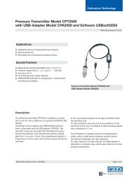
1 Main switch 6 Display<br />
2 Fuse 7 Pitot line manual vent knob<br />
3 Static line output 8 Static line manual vent knob<br />
4 Pitot line output 9 External power socket<br />
5 Key board<br />
FIG. - 1 ADTS P/N <strong>MPS</strong> <strong>38B</strong> FRONT PANEL<br />
CMPP/<strong>MPS</strong><strong>38B</strong>/0207a<br />
<strong>MPS</strong><strong>38B</strong> VERS.a0207 D.MARCHIORI COPYRIGHT 4
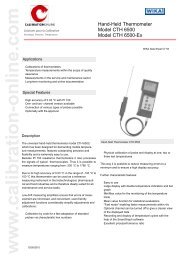
FIG. - 2 KEY BOARD LAY OUT<br />
CMPP/<strong>MPS</strong><strong>38B</strong>/0207a<br />
<strong>MPS</strong><strong>38B</strong> VERS.a0207 D.MARCHIORI COPYRIGHT 5
CMPP/<strong>MPS</strong><strong>38B</strong>/0207a<br />
SECTION 1 INTRODUCTION AND GENERAL INFORMATION<br />
IMPORTANT NOTES<br />
This manual contains the operating procedures for the <strong>MPS</strong> <strong>38B</strong> air data test set <strong>and</strong> is<br />
suitable for both workshop <strong>and</strong> flight-line servicing.<br />
Safety.<br />
The <strong>MPS</strong> <strong>38B</strong> is designed to be safe when operated in the manner described in this<br />
manual, it should be used only in the described way <strong>and</strong> for no other purposes. The<br />
manual contains Safety <strong>Instructions</strong> that must be followed, the instructions are either<br />
warnings or cautions given to protect the Operator <strong>and</strong> the equipment from damage.<br />
Use trained technicians <strong>and</strong> good engineering practices for all the procedures in this<br />
manual.<br />
Pressure.<br />
Never apply pressure greater than the maximum safe working pressure to the<br />
equipment.<br />
Toxic Materials.<br />
There are no known toxic materials used in the manufacture or build st<strong>and</strong>ard of this<br />
<strong>MPS</strong> <strong>38B</strong>.<br />
Maintenance <strong>and</strong> Repair.<br />
The <strong>MPS</strong> <strong>38B</strong> is to be maintained <strong>and</strong> repaired using the approved procedures <strong>and</strong> be<br />
carried out only by authorised agencies or the manufacturer.<br />
Information <strong>and</strong> Advice.<br />
Contact the manufacturer, subsidiary or agent for further detailed technical advice.<br />
Note.<br />
This <strong>Manual</strong> is applicable starting from SW Version 1.16.<br />
Important notes.<br />
• The manual vent valves on the front panel must be completely closed before the<br />
start of testing.<br />
• Connect the ADTS to the static <strong>and</strong> pitot ports only after the start up procedure is<br />
finished.<br />
• For optimum operation <strong>and</strong> highest precision, the <strong>MPS</strong> <strong>38B</strong> should be operated<br />
with the front panel face up.<br />
• When transporting the <strong>MPS</strong> <strong>38B</strong> in an unpressurised aircraft utilise the case<br />
VENT /SEAL valve to prevent damage by equalising the internal – external<br />
pressure.<br />
<strong>MPS</strong><strong>38B</strong> VERS.a0207 D.MARCHIORI COPYRIGHT 6
1.1 INTRODUCTION<br />
CMPP/<strong>MPS</strong><strong>38B</strong>/0207a<br />
This manual contains all the instructions <strong>and</strong> procedures necessary to operate <strong>and</strong><br />
calibrate the <strong>Air</strong> <strong>Data</strong> <strong>Test</strong> <strong>Set</strong> P/N <strong>MPS</strong> <strong>38B</strong> manufactured by DMA.<br />
1.2 GENERAL INFORMATION<br />
The <strong>MPS</strong> <strong>38B</strong> is a compact, lightweight <strong>and</strong> practical instrument suitable for the<br />
measurement <strong>and</strong> generation of related pressures to simulate altitude, airspeed <strong>and</strong><br />
their respective rates.<br />
1.3 MAIN PARTS<br />
The <strong>MPS</strong> <strong>38B</strong> main parts are:<br />
• Static <strong>and</strong> Pitot lines pneumatic components.<br />
• Electronic circuits including a microprocessor based system necessary to<br />
measure <strong>and</strong> control pressures<br />
• Accumulator tanks<br />
• High Performance Piezoresistive Pressure sensors<br />
• Compressor – vacuum membrane type pump unit.<br />
• Key board <strong>and</strong> Display.<br />
1.4 MAIN TECHNICAL SPECIFICATION<br />
The <strong>MPS</strong> <strong>38B</strong> is a fully automatic ADTS with Operator input via a 32 element<br />
keyboard. The comm<strong>and</strong>ed <strong>and</strong> current values of pressure, altitude, airspeed <strong>and</strong><br />
associated rates are shown on an LCD display with a matrix of 4 rows <strong>and</strong> 20<br />
characters.<br />
Function<br />
• Generation of Pressure/altitude<br />
• Generation of Pressure/airspeed<br />
• Simultaneous generation of altitude <strong>and</strong> airspeed<br />
• Generation of altitude rate (climb or dive ) (feet/min)<br />
• Generation of airspeed rate (increasing or decreasing ) (knots/min)<br />
• Leakage test<br />
• Automatic Vent<br />
• Maximum set values: the ADTS allows the simple setting of maximum values<br />
(limits ) to which the unit can operate. It is delivered with the following default<br />
values set by the manufacturer:<br />
• Max Altitude: Control 50.000 feet,: Measure 65.000 feet<br />
• Min. altitude: -2.000 feet<br />
• Max. airspeed: 700 knots<br />
• Max vertical speed: 6.000 feet/min.<br />
• <strong>Set</strong> airspeed rate: 300 kt/min.<br />
Measure Units<br />
The operator can change the default units as required. In addition, if so required, the<br />
manufacturer can deliver the ADTS with different default units.<br />
- Default Engineering Units are: feet, knots, Inches Hg.<br />
<strong>MPS</strong><strong>38B</strong> VERS.a0207 D.MARCHIORI COPYRIGHT 7
CMPP/<strong>MPS</strong><strong>38B</strong>/0207a<br />
- The following additional engineering units are available by pressing the<br />
appropriate key:<br />
- for Altitude: metre <strong>and</strong> hm<br />
- for Pressure: hPa, Pa, kPa, mmHg <strong>and</strong> p.s.i.<br />
- for <strong>Air</strong>speed: mph <strong>and</strong> kmph.<br />
Power<br />
90 to 240 VAC <strong>and</strong> 50 to 400 Hz.<br />
Accuracy<br />
- Altitude accuracy:(after 15 min. warm-up)<br />
12 months<br />
recalibration<br />
± 3 ft @ s.l.<br />
± 5 ft @ 30.000 ft<br />
± 20 ft @ 50.000 ft<br />
- <strong>Air</strong>speed accuracy: +/- 0.2 kts at 300 kts<br />
Pressure Media<br />
<strong>Air</strong><br />
Environment limits<br />
• The ADTS can safely be operated in an ambient temperature ranging from 0°C up<br />
to 50°C.<br />
• CE compliant<br />
Physical Specifications<br />
• Weight: light weight, 22 lbs, easy to carry to the cockpit<br />
• Dimensions: L 17”, W 14$, H 7” (43, 36,18 cm.)<br />
<strong>MPS</strong><strong>38B</strong> VERS.a0207 D.MARCHIORI COPYRIGHT 8
CMPP/<strong>MPS</strong><strong>38B</strong>/0207a<br />
SECTION 2 - <strong>MPS</strong> <strong>38B</strong> DESCRIPTION AND CONTROL KEYS<br />
2.1 GENERAL DESCRIPTION<br />
The DMA <strong>MPS</strong> <strong>38B</strong> is an automatically controlled low cost <strong>Air</strong> <strong>Data</strong> <strong>Test</strong> solution for<br />
troubleshooting <strong>and</strong> certification of aircraft pitot-static systems with the accuracy<br />
requirements as detailed above.<br />
The <strong>MPS</strong> <strong>38B</strong> instrument is simple <strong>and</strong> fast to use. The operator interface is easy to<br />
underst<strong>and</strong> by both experts <strong>and</strong> first time users. All testing <strong>and</strong> troubleshooting with the<br />
<strong>MPS</strong> <strong>38B</strong> is carried out via an intuitively arranged colour-coded keypad on the front<br />
panel. All the data necessary for the testing are displayed on a large, easy to read LCD<br />
display.<br />
Comm<strong>and</strong>ed <strong>and</strong> measured test values are simultaneously displayed at all times.<br />
The <strong>MPS</strong> <strong>38B</strong> incorporates an internal on-dem<strong>and</strong> pump unit: to increase the pump life<br />
the internal vacuum <strong>and</strong> pressure source runs only when required by the control system.<br />
The <strong>MPS</strong> <strong>38B</strong> comes equipped with built-in protection to safeguard the test set itself <strong>and</strong><br />
the instruments under test, ensuring no more damaged instruments or air data test sets.<br />
Both the test set <strong>and</strong> instruments under test are protected by the safety conscious <strong>MPS</strong><br />
<strong>38B</strong> design features. The pressure condition of Ps greater than Pt, that is negative Qc,<br />
(negative airspeed) is prevented in both the manual venting <strong>and</strong> automatic operating<br />
modes.<br />
The Unit Under <strong>Test</strong> (UUT) is safely isolated in the event of any power loss.<br />
The <strong>MPS</strong> <strong>38B</strong> is designed to reject any comm<strong>and</strong>ed values which exceed preprogrammed<br />
limits. Limits values are password protected.<br />
The <strong>MPS</strong> <strong>38B</strong> provides facilities to enable in-house calibrations to be performed by the<br />
user if desired.<br />
Using a transfer calibration st<strong>and</strong>ard (for example the DMA's own PAMB 6 or PAMB7,<br />
the <strong>MPS</strong> <strong>38B</strong> can be calibrated in typically less than 20 minutes.<br />
Calibration is performed by software adjustment only. No mechanical adjustments are<br />
required to the <strong>MPS</strong> <strong>38B</strong>. Calibration factors are password protected for security.<br />
2.2 PHYSICAL DESCRIPTION<br />
The <strong>MPS</strong> <strong>38B</strong> consists of a power supply, digital control cards, pressure sensors, <strong>and</strong><br />
pneumatic control components. It is packaged within a lightweight HDPE (high density<br />
polyethylene) case.<br />
The front panel provides operating controls <strong>and</strong> displays, pressure fittings <strong>and</strong><br />
connectors for external control.<br />
A view of the <strong>MPS</strong> <strong>38B</strong> console is displayed in Figure 1.<br />
2.3 KEYPAD KEYS<br />
Control <strong>and</strong> data entry of the <strong>MPS</strong> <strong>38B</strong> is via a keypad on the front panel (Fig. 2). Five<br />
rows of keys provide access to all of the <strong>MPS</strong> <strong>38B</strong>’s control <strong>and</strong> operational functions.<br />
Keys are colour coded for ease of use. A telephone format 0 to 9 keypad is included for<br />
entry of target values.<br />
<strong>MPS</strong><strong>38B</strong> VERS.a0207 D.MARCHIORI COPYRIGHT 9
First Row keys:<br />
CMPP/<strong>MPS</strong><strong>38B</strong>/0207a<br />
HALT: when pressed the <strong>MPS</strong> <strong>38B</strong> remains in the CONTROL MODE but automatically<br />
enters, as COMMANDED (target) air data parameters, those values which are present<br />
at the instant the HALT key is pressed, thereby halting the operation at the existing<br />
values. The HALT key can be considered as a “panic button” to be used when it is<br />
necessary to freeze the pressures at the current values.<br />
LIMITS: is used to enter the LIMITS MENU. This menu is used to view or change the<br />
default limit values as they have been pre-set from the factory. To return to CONTROL<br />
MODE of operation, the LIMITS key must be pressed a second time. Refer to Section 6.<br />
UNITS: is used to enter the UNITS MENU. The <strong>MPS</strong> <strong>38B</strong> can change the measured<br />
units for altitude, airspeed <strong>and</strong> pressures. Refer to Section 6.<br />
MEM: is used to memorize new parameters.<br />
IAS / TAS is used to toggle from I.A.S. (Indicated <strong>Air</strong> Speed) to T.A.S. (True <strong>Air</strong> Speed)<br />
<strong>and</strong> vice versa. Refer to Section 9 para.10.<br />
SHIFT: has the same function as a shift key on a computer keyboard. It is used together<br />
with other keys to comm<strong>and</strong> alternate key functions (e.g. [SHIFT] + [0] to activate the<br />
“Fine Tuning”) .<br />
A summary of SHIFT key operations is shown in Section 9, para. 11.<br />
BACKSPACE: is used to delete the last entered digit.<br />
Second Row Keys, left side:<br />
MEAS: the “MEASUREMENT” key is used to turn off the operation of the pressure<br />
control system leaving only the pressure measuring system active. This function is used<br />
to achieve extra accuracy for measuring pressures statically to avoid any controller<br />
induced effects.<br />
The RUN key is used to return the <strong>MPS</strong> <strong>38B</strong> to CONTROL MODE.<br />
VENT: is used to vent the pressure in the static <strong>and</strong> pitot lines to ambient pressure. This<br />
function allows for the safe disconnection of test lines from the aircraft / UUT at the end<br />
of testing. The RUN key is used to restore the <strong>MPS</strong> <strong>38B</strong> to the CONTROL MODE, after<br />
the vent function has been activated.<br />
LEAK: is used to automatically perform a leak test using the built in timer/stopwatch<br />
function of the <strong>MPS</strong> <strong>38B</strong>. The RUN key is used to restore the test set to the CONTROL<br />
MODE of operation, after LEAK key function is complete.<br />
<strong>MPS</strong><strong>38B</strong> VERS.a0207 D.MARCHIORI COPYRIGHT 10
Second <strong>and</strong> Third Row Keys, right side:<br />
CMPP/<strong>MPS</strong><strong>38B</strong>/0207a<br />
The UP ( DOWN ) triangle keys ▲ (or ▼) are used:<br />
- to increase (decrease) the different parameters (ALTITUDE, AIRSPEED, RATE OF<br />
CHANGE, PRESSURES) by a selected digit value;<br />
- in the UNITS MENU, for changing the parameters units;<br />
- in the DISPLAY MENU to adjust the display (brightness <strong>and</strong> contrast).<br />
Third Row Keys, left:<br />
RUN: is used to initiate or to return the equipment to CONTROL MODE.<br />
NOTE<br />
RUN is the most frequently used key in the general operation of the <strong>MPS</strong><br />
<strong>38B</strong>.<br />
Qc/Pitot: is used to toggle switch between the differential pressure (Qc) <strong>and</strong> the pitot<br />
pressure (Pt).<br />
ALRT/ASPRT: is a toggle switch used to select either the ALTITUDE RATE, AIRSPEED<br />
RATE, STATIC PRESSURE RATE or PITOT PRESSURE RATE.<br />
The default AIRSPEED RATE value is 300 knots/min. The default ALTITUDE RATE is<br />
3000 Ft/min.<br />
Fourth <strong>and</strong> Fifth Row Keys, left:<br />
The ← or → keys are used to navigate around the display in the CONTROL, LIMITS <strong>and</strong><br />
UNITS menus. These keys are used to move the cursor“>” to the desired input zone for<br />
entry of a specific value using the numerical keypad.<br />
The DIGIT key is used to select different digit on each <strong>Air</strong> <strong>Data</strong> Parameter.<br />
The ENTER key is used to input desired data the <strong>MPS</strong> <strong>38B</strong>. The operation is the same<br />
as an “Enter” key on a computer keyboard.<br />
Numerical keypad, centre:<br />
This keypad is a st<strong>and</strong>ard telephone layout ten-number keypad. The numerical keys (0–<br />
9) are used to enter any desired value of the various controlled parameters. After keying<br />
in number value, the ENTER key is always required to enter, confirm, the completed<br />
value into the system.<br />
NOTE<br />
For some optional operations, number keys may be used in combination with<br />
the SHIFT key, to access additional functions.<br />
<strong>MPS</strong><strong>38B</strong> VERS.a0207 D.MARCHIORI COPYRIGHT 11
CMPP/<strong>MPS</strong><strong>38B</strong>/0207a<br />
The decimal point key (.) is used to input decimal points when required (e.g. airspeed).<br />
The minus key (–) is used to set negative altitudes (e.g. when static pressure is higher<br />
than the ambient).<br />
The 000 key is used to enter thous<strong>and</strong>s on numerical keypads, if allowed by the<br />
programmed limits.<br />
<strong>MPS</strong><strong>38B</strong> VERS.a0207 D.MARCHIORI COPYRIGHT 12
CMPP/<strong>MPS</strong><strong>38B</strong>/0207a<br />
SECTION 3 - OPERATIONAL MODES, MENUS AND DISPLAYS<br />
NOTE<br />
The <strong>MPS</strong> <strong>38B</strong> has multiple operational modes, menus <strong>and</strong> displays. Modes<br />
are defined by the operating characteristics that are relevant during operation<br />
in the specific mode. Menus refer to operations <strong>and</strong> information that are<br />
accessible <strong>and</strong> changeable on the LCD screen. Displays refer to data that is<br />
shown in a read-only format on the screen. Display screens are read only;<br />
they do not allow parameters to be entered or changed.<br />
3.1 CONTROL MODE<br />
This is the primary mode for control of the <strong>MPS</strong> <strong>38B</strong>. <strong>Air</strong> data parameter entry <strong>and</strong> all the<br />
operational/control functions are all performed in this mode. The access to CONTROL<br />
MODE is through the CONTROL MENU.<br />
Entry to the CONTROL MODE is by pressing the RUN key.<br />
Return to CONTROL MODE is by pressing the RUN key at any time from any other<br />
mode of operation.<br />
3.1.1 CONTROL MODE MENU<br />
The CONTROL MODE MENU is displayed when the <strong>MPS</strong> <strong>38B</strong> is in CONTROL MODE.<br />
SIMULATED ( CURRENT ) values are displayed on the “SIM” line of the display while<br />
the COMMANDED (TARGET) values are displayed on the “CMD” line of the display.<br />
<strong>Air</strong> data parameters will be displayed on the upper two lines of the LCD screen (upper<br />
“CMD” <strong>and</strong> “SIM” lines) <strong>and</strong> the equivalent pressure parameters will be displayed on the<br />
lower two lines of the screen (lower “CMD” <strong>and</strong> “SIM” lines).<br />
When the CONTROL MODE MENU is displayed, the word “CNTRL” will appear in the<br />
lower right-h<strong>and</strong> corner of the LCD screen.<br />
3.2 MEASURE MODE<br />
MEASURE MODE is used to place the system into the mode where only the pressure<br />
measuring system is active <strong>and</strong> the control system is turned off. The unit under test<br />
(UUT) is now completely isolated from the pressure generator <strong>and</strong> precise<br />
measurements can be obtained when the line pressures in the UUT under test are<br />
stabilized. Whenever a precision measurement is required, in particular when large<br />
volumes are involved, the MEAS function should be used: all control functions are<br />
disabled <strong>and</strong> only sensor measurement functions are active. MEASUREMENT MODE<br />
can be accessed from all menus.<br />
Entry to the MEASUREMENT MODE is by pressing the MEAS key.<br />
Return to CONTROL MODE is by pressing the RUN key or other modes by pressing the<br />
required mode entry key.<br />
<strong>MPS</strong><strong>38B</strong> VERS.a0207 D.MARCHIORI COPYRIGHT 13
3.2.1 MEASURE MODE MENU<br />
CMPP/<strong>MPS</strong><strong>38B</strong>/0207a<br />
The MEASURE MODE MENU is displayed when the <strong>MPS</strong> <strong>38B</strong> is in MEASURE MODE.<br />
When the MEASURE MODE MENU is displayed, the word “MEAS” will appear in the<br />
lower right-h<strong>and</strong> corner of the LCD screen.<br />
3.3 VENT MODE<br />
This mode is used to vent the pitot <strong>and</strong> static ports of the <strong>MPS</strong> <strong>38B</strong> to the ambient<br />
pressure condition. VENT MODE operates as follows: when the VENT key is pressed<br />
the <strong>MPS</strong> <strong>38B</strong> will automatically set the airspeed to zero , <strong>and</strong> an altitude equal to<br />
ambient pressure, then initiate a descent with a rate of 3000 ft/min. When the ambient<br />
pressure is reached, the legend: “AMBIENT PRESSURE REACHED” will be displayed.<br />
To return to CONTROL MODE press the RUN key.<br />
3.3.1 VENT MODE MENU<br />
The VENT MODE MENU is displayed when the <strong>MPS</strong> <strong>38B</strong> is in VENT MODE. When the<br />
VENT MODE MENU is displayed, the word “VENT” will appear in the lower right-h<strong>and</strong><br />
corner of the LCD screen.<br />
3.4 LEAK MODE<br />
The LEAK MODE initiates the automatic leak test <strong>and</strong> the internal timer/stopwatch<br />
measurement feature of the <strong>MPS</strong> <strong>38B</strong>.<br />
LEAK MODE access is through the LEAK MENU.<br />
Entry to the LEAK MODE is by pressing the LEAK key.<br />
Return to CONTROL MODE is by pressing the RUN key.<br />
3.4.1 LEAK MODE DISPLAY<br />
The LEAK MODE DISPLAY is shown when the <strong>MPS</strong> <strong>38B</strong> is in LEAK MODE. When the<br />
LEAK MODE is in operation, ALITUDE RATE (“AltRate”) <strong>and</strong> AIRSPEED RATE (“Asp<br />
Rate”) plus the elapsed time in seconds will be displayed on the upper two lines of the<br />
LCD screen.<br />
The legend “LEAK” appears in the lower right-h<strong>and</strong> corner of the LCD screen.<br />
3.5 LIMITS MODE<br />
The LIMITS MODE allows the operator to change the current limits of all the functions.<br />
Access to the LIMITS MODE is via the LIMITS MENU.<br />
The LIMITS key is used to enter the LIMITS MENU. To return to CONTROL MODE or<br />
any other mode, the LIMITS key must be pressed a second time.<br />
3.5.1 LIMITS MODE MENU<br />
The LIMITS MODE MENU is displayed when the <strong>MPS</strong> <strong>38B</strong> is in LIMITS MODE. When<br />
the LIMITS MODE MENU is displayed, two vertical columns of parameters will be<br />
shown, starting with the parameter “AlMx >” (altitude max.) Refer to Section 6.<br />
3.6 UNIT MODE<br />
The UNIT MODE allows the operator to change the current measurement units. Access<br />
to the UNIT MODE is via the UNIT MENU.<br />
The UNIT key is used to enter UNIT MENU. To return to CONTROL MODE the UNIT<br />
key must be pressed a second time.<br />
<strong>MPS</strong><strong>38B</strong> VERS.a0207 D.MARCHIORI COPYRIGHT 14
3.6.1 UNIT MODE MENU<br />
CMPP/<strong>MPS</strong><strong>38B</strong>/0207a<br />
The UNIT MODE MENU is displayed when the <strong>MPS</strong> <strong>38B</strong> is in UNIT MODE. When the<br />
UNIT MODE MENU is displayed, a row containing measure units parameters will be<br />
shown, starting with the parameter “Ft”.<br />
Refer to Section 6.<br />
<strong>MPS</strong><strong>38B</strong> VERS.a0207 D.MARCHIORI COPYRIGHT 15
SECTION 3 - START UP PROCEDURE<br />
• Place the <strong>MPS</strong> <strong>38B</strong> with the panel face up.<br />
• Connect the power cord to the military style connector on the front panel.<br />
CMPP/<strong>MPS</strong><strong>38B</strong>/0207a<br />
• Leave static <strong>and</strong> pitot lines disconnected. Static <strong>and</strong> pitot lines should be connected<br />
only after start-up is complete <strong>and</strong> the test set is at ambient pressure.<br />
• Turn the power toggle switch to “ON”.<br />
The <strong>MPS</strong> <strong>38B</strong> display will first illuminate; then reads the serial number of the unit,<br />
operation time <strong>and</strong> last calibration date.<br />
When the start-up <strong>and</strong> self-check is completed, there are two possible scenarios:<br />
If the ambient altitude measured in the static line is less than 8,000 ft, the <strong>MPS</strong> <strong>38B</strong> will<br />
then automatically vent the pitot <strong>and</strong> static lines to ambient. The pitot <strong>and</strong> static ports will<br />
be automatically zeroed. When the venting process is completed, the display will read<br />
"AMBIENT PRESSURE REACHED". After this reading is displayed, press RUN to<br />
initiate use in CONTROL MODE.<br />
If the ambient altitude measured in the static line is greater than 8,000 ft, the following<br />
conditions will be automatically imposed:<br />
• the <strong>Set</strong> Altitude will be adjusted to the value measured in the static line,<br />
• the <strong>Set</strong> <strong>Air</strong>speed will be adjusted to the value measured in the pitot line,<br />
• the <strong>Set</strong> AL Rate will be set at a fixed value (normal default 3000 ft/min).<br />
The operator is then able to select RUN to reduce these high parameter values to either<br />
suitable test points for the UUT, or to return to ambient conditions<br />
To vent the <strong>MPS</strong> <strong>38B</strong> <strong>and</strong> zero the pitot line, press the VENT key. Again wait until<br />
"AMBIENT PRESSURE REACHED" is displayed, press RUN to initiate in CONTROL<br />
MODE.<br />
NOTE<br />
For maximum accuracy of AIRSPEED measurements at low airspeed, relate<br />
to Section 7.<br />
<strong>MPS</strong><strong>38B</strong> VERS.a0207 D.MARCHIORI COPYRIGHT 16
SECTION 4 - ENTERING AIR DATA TEST PARAMETERS<br />
CMPP/<strong>MPS</strong><strong>38B</strong>/0207a<br />
<strong>Air</strong> <strong>Data</strong> Parameters (ALTITUDE, AIRSPEED <strong>and</strong> RATE) can be comm<strong>and</strong>ed (entered)<br />
in two modes:<br />
1) by operating the <strong>MPS</strong> <strong>38B</strong> in the CONTROL MODE. When the CONTROL MODE is<br />
active the <strong>MPS</strong> <strong>38B</strong> starts to change the pressures as soon as a new air data value is<br />
entered.<br />
2) by operating the <strong>MPS</strong> <strong>38B</strong> in MEASURE MODE. If it is desired that the <strong>MPS</strong> <strong>38B</strong><br />
starts to change pressures only after all the new air data parameters have been<br />
entered, it is necessary to go to the MEASURE MODE, enter all the new target<br />
values <strong>and</strong> then return to CONTROL MODE by pressing the RUN key, then all the<br />
new values will be activated together.<br />
New target values can also be entered by using the triangle keys ▲ (to increase) or ▼<br />
(to decrease)<br />
NOTE<br />
If a value of ALTITUDE or AIRSPEED or ALTITUDE RATE greater than the<br />
actual limits (the values programmed in the LIMITS MENU ) is selected, the<br />
value will be not accepted <strong>and</strong> instead the actual limit value will automatically<br />
be entered . As an example, if an airspeed value of 999 knots is entered while<br />
the limit value is set at 400 knots, 400 knots will be the comm<strong>and</strong>ed value into<br />
the equipment, when the ENTER key is pressed.<br />
4.1 METHOD 1, ENTERING SPECIFIC COMMAND VALUES<br />
The <strong>MPS</strong> <strong>38B</strong> is operated by entering COMMAND (“CMD”) line values for ALTITUDE,<br />
AIRSPEED <strong>and</strong> RATE OF CHANGE in the CONTROL MODE. A COMMAND value may<br />
be entered in any of the COMMAND LINE input zones to select ALTITUDE, AIRSPEED<br />
<strong>and</strong> RATE. To enter a COMMAND value, the cursor (>) must be in the desired input<br />
zone. Arrow keys ← or → are used to navigate the cursor (>) to the desired input zone.<br />
The arrow keys can be used at any time when the <strong>MPS</strong> <strong>38B</strong> is in CONTROL or<br />
MEASURE MODE.<br />
The right <strong>and</strong> left arrow keys are used to move among each of the three parameter<br />
columns (ALTITUDE, AIRSPEED <strong>and</strong> RATE) <strong>and</strong> additionally move up <strong>and</strong> down on the<br />
three display screen parameter columns (the ALTITUDE column, AIRSPEED column<br />
<strong>and</strong> RATE column). By pressing the right or left arrow keys the cursor (>) navigates<br />
among the three parameter columns on the upper air data COMMAND (“CMD”) LINE<br />
(ALTITUDE, AIRSPEED <strong>and</strong> RATE) <strong>and</strong> the lower COMMAND LINE for the pressure<br />
engineering units.<br />
4.1.1 ALTITUDE COMMAND<br />
To enter an altitude, scroll the cursor to “ ALTITUDE “ in the COMMAND (“CMD”) LINE<br />
input zone. Enter the target value by digitizing it on the keypad (20000 feet for example).<br />
<strong>MPS</strong><strong>38B</strong> VERS.a0207 D.MARCHIORI COPYRIGHT 17
CMPP/<strong>MPS</strong><strong>38B</strong>/0207a<br />
If an incorrect number is selected, the BACKSPACE key can be used to erase the<br />
incorrect digit. After the number is erased with the BACKSPACE key, the correct number<br />
can be entered. When the correct ALTITUDE has been digitized, press the ENTER key<br />
to activate the new value.<br />
4.1.2 AIRSPEED COMMAND<br />
Scroll the cursor to AIRSPEED “ in the COMMAND ( “CMD” ) LINE input zone. Enter the<br />
target value by digitizing it on the keypad (300 knots, for example). If an incorrect<br />
number is selected, the BACKSPACE key can be used to erase the incorrect digit.<br />
When the correct AIRSPEED has been digitized, press the ENTER key to validate the<br />
new value.<br />
4.1.3 ALTITUDE RATE COMMAND (RATE OF CHANGE)<br />
Scroll the cursor to “ RATE “ in the COMMAND (“CMD”) LINE input zone. Enter the<br />
target value by digitizing it on the keypad (3000 ft/min. for example). If an incorrect<br />
number is selected, the BACKSPACE key can be used to erase the incorrect digit.<br />
When the correct RATE has been digitized, press the ENTER key to activate the new<br />
value.<br />
The <strong>MPS</strong> <strong>38B</strong> will begin to achieve the entered COMMAND LINE value immediately.<br />
WARNING<br />
When it is desired that the <strong>MPS</strong> <strong>38B</strong> will start to reach test values only after<br />
all the parameters have been properly entered, enter the comm<strong>and</strong>ed values<br />
in the MEASURE MODE; then enter the CONTROL MODE by pressing the<br />
RUN key. All the new comm<strong>and</strong>ed values will now be actioned.<br />
4.1.4 CONTROL MENU DISPLAY<br />
In CONTROL MODE the display will appear as in the following example, where the<br />
engineering measure units are feet, knots <strong>and</strong> feet/min., <strong>and</strong> the pressure units are<br />
inHg:<br />
ALTITUD<br />
E<br />
AIRSPEE<br />
D<br />
RATE<br />
SIM 1934 149.5 3000 SIM<br />
CMD 5000 300 3000 CMD<br />
SIM 27.890 1.082 0.233 SIM<br />
CMD 24.896 4.534 CNTR CMD<br />
Pst Qc/Ptot MACH<br />
FIG. 3 - DISPLAY LAYOUT IN THE CONTROL MODE<br />
<strong>MPS</strong><strong>38B</strong> VERS.a0207 D.MARCHIORI COPYRIGHT 18
4.2 METHOD 2-PRESSURES VALUES COMMAND WITH DIGIT CHANGE<br />
CMPP/<strong>MPS</strong><strong>38B</strong>/0207a<br />
<strong>Air</strong> <strong>Data</strong> Parameter values can also be modified by using the “Digit" function. As with the<br />
direct value entry method above, “Digit" function can be used in CONTROL or in<br />
MEASURE MODE.<br />
“Digit" function provides a quick way to change an <strong>Air</strong> <strong>Data</strong> Parameter.<br />
The UP (DOWN) triangle keys ▲ (or ▼) <strong>and</strong> DIGIT key are used on the “Digit"<br />
Function”. Once selected with ← or → keys, each <strong>Air</strong> <strong>Data</strong> Parameter has one digit<br />
flashing. Use ▲ (or ▼) keys to increase or decrease the flashing digit by a quantity 1.<br />
Use DIGIT key (or SHIFT DIGIT keys) to change the parameter digit that is to be altered.<br />
For example: Altitude parameter is selected, <strong>and</strong> set value is 6543:<br />
if 6 is the flashing digit, pushing ▲ (or ▼) keys the set Altitude can be modified to 7543,<br />
8543.... (increasing), or to 5543, 4543... (decreasing);<br />
use DIGIT key (or SHIFT DIGIT keys) until the another digit starts flashing, for example<br />
the last one (3); now pushing ▲ (or ▼) keys the set Altitude can be modified to 6544,<br />
6545 increasing), or to 6542, 6541 (decreasing).<br />
The “Digit” function can increase (or decrease) the magnitude of a value by units, tens or<br />
hundreds, 1,10,100 … depending on the flashing digit.<br />
Using the “Digit" function, once an <strong>Air</strong> data parameter is selected, any digit can be<br />
modified separately from the others. A continuous increase (decrease) of the parameter<br />
is possible when the ▲ (or ▼) keys are maintained pressed.<br />
4.3 ACOUSTIC ALARM FUNCTION<br />
When the SIMulated (Actual) values are almost at the CoMmanD (Desired) values<br />
(around 10 feet <strong>and</strong> 1 knot) an acoustic alarm will start sounding (beep-beep) to warn<br />
the operator that the <strong>MPS</strong> <strong>38B</strong> is approaching the target values. Press (SHIFT 2) key to<br />
remove (or reactivate) the beep-beep.<br />
<strong>MPS</strong><strong>38B</strong> VERS.a0207 D.MARCHIORI COPYRIGHT 19
SECTION 5 - ADVANCED OPERATIONS<br />
5.1 DIFFERENT RATE COMMANDS<br />
CMPP/<strong>MPS</strong><strong>38B</strong>/0207a<br />
The ALRT/ASPRT key is used to toggle <strong>and</strong> select the different rates.<br />
Below the word “RATE“ a letter in front of the numerical value will indicate which is the<br />
active function: for example the letter “A“ will indicate to the operator that the rate<br />
controlled is the ALTITUDE RATE. The Altitude Rate is the default.<br />
By pressing the ALRT/ASPRT key, the letter “S” will appear in front of the value shown<br />
to display that the the equipment is now controlling the AIRSPEED RATE.<br />
NOTE: The equipment has an AIRSPEED RATE default value of 300 Kts/min.<br />
5.2 COMMAND IN DIRECT PRESSURE UNITS<br />
If desired, direct pressure units can be used to enter pitot or static pressure values or Qc<br />
differential pressure values (pitot pressure – static pressure). For this operation, the<br />
second COMMAND (“CMD”) LINE input zones are used. The comm<strong>and</strong>ed default<br />
pressure value is displayed in inches of Mercury or inHg.<br />
5.2.1 ENTERTING AN ALTITUDE USING DIRECT PRESSURE VALUES<br />
Navigate the cursor to the lower COMMAND LINE input zone for Pst (Static Pressure).<br />
The desired pressure value can be entered by using a direct number value or by<br />
changing digits.<br />
Enter the desired specific pressure value by pressing the number keys (18.00 inHg for<br />
example). If an incorrect number is selected, the BACKSPACE key can be used to erase<br />
the incorrect digit. After the incorrect number has been erased with the BACKSPACE<br />
key, the correct number can be entered. When the correct ALtitude equivalent pressure<br />
is entered, press the ENTER key to confirm the new value.<br />
5.2.2 AIRSPEED COMMAND USING DIFFERENTIAL PRESSURE VALUES<br />
(Qc = Differential Pressure)<br />
Navigate the cursor to the COMMAND (“CMD”) LINE input zone for Qc (Differential<br />
Pressure). The desired pressure value can be entered by using a direct number value or<br />
by changing digits.<br />
Enter the desired specific pressure value by pressing the number keys (10,55 inHg for<br />
example). If an incorrect number is selected, the BACKSPACE key can be used to erase<br />
the incorrect digit. After the incorrect number has been erased with the BACKSPACE<br />
key, the correct number can be entered. When the correct Qc is entered, press the<br />
ENTER key to confirm the new value.<br />
5.3 SPECIFIC PITOT PRESSURE VALUE COMMAND<br />
To enter a specific pitot pressure, use the Qc/Ptot key, “Qc” for differential pressure <strong>and</strong><br />
Ptot for Pitot pressure (= Static pressure + Differential Pressure). Qc/Ptot key is used to<br />
<strong>MPS</strong><strong>38B</strong> VERS.a0207 D.MARCHIORI COPYRIGHT 20
CMPP/<strong>MPS</strong><strong>38B</strong>/0207a<br />
toggle between the normal default setting of Differential Pressure (Qc), <strong>and</strong> the<br />
alternative Pitot Pressure (Ptot).<br />
When the Qc/Ptot key is used to toggle to PITOT PRESSURE (Ptot), the values of<br />
TOTAL PRESSURE will appear. Enter the desired PITOT PRESSURE (Ptot) <strong>and</strong> press<br />
the ENTER key to confirm the new value. Use the Qc/Ptot key to toggle again to<br />
DIFFERENTIAL PRESSURE ( Qc), if required<br />
5.4 LEAK TEST MODE OPERATION<br />
The LEAK TEST MODE performs a leak test of the static <strong>and</strong> pitot lines using a built-in<br />
timing function. Leak rates for pitot <strong>and</strong> static lines are calculated every second <strong>and</strong> are<br />
automatically shown in ft/min. <strong>and</strong> kt/min. in the LEAK MODE DISPLAY screen.<br />
Select the leak test function by pressing the LEAK key. The LEAK DISPLAY will appear.<br />
The LEAK DISPLAY will begin counting the seconds <strong>and</strong> displaying the leak rates for<br />
the pitot <strong>and</strong> static circuits.<br />
ALTITUD<br />
E<br />
AIRSPEE<br />
D<br />
RATE<br />
SIM sec AltRate AspRate SIM<br />
CMD 66 -6 0.1 CMD<br />
SIM 20.593 0.504 0.189 SIM<br />
CMD 28.577 0.481 LEAK CMD<br />
Pst Qc/Ptot MACH<br />
FIG. 4 - DISPLAY LAYOUT IN THE LEAK MODE<br />
For the best measurement results, wait until the values in the LEAK DISPLAY are<br />
stabilized after pressing the LEAK key. Typically this will happen after about one<br />
minute.<br />
When the stabilization has occurred, press the LEAK key once again to reset the clock<br />
for a fresh start of a leak test.<br />
To return to the previous menu, press the RUN key.<br />
5.5 VENT MODE FUNCTION<br />
The VENT MODE function is used to restore the unit under test to ambient pressure.<br />
This is important for safe disconnection of the hoses.<br />
VENT MODE operates as follows: when the VENT key is pressed the <strong>MPS</strong> <strong>38B</strong><br />
automatically sets the airspeed to zero, <strong>and</strong> the altitude to ambient pressure, <strong>and</strong> then<br />
initiates a descent with a rate of 3000 ft/min. When the ambient pressure is reached, the<br />
legend: “AMBIENT PRESSURE REACHED” will be displayed.<br />
To return to CONTROL MODE press the RUN key.<br />
Entry to the VENT MODE is by pressing the VENT key.<br />
From VENT MODE, only CONTROL MODE or HALT MODE can be accessed. To return<br />
to CONTROL MODE press the RUN key.<br />
<strong>MPS</strong><strong>38B</strong> VERS.a0207 D.MARCHIORI COPYRIGHT 21
5.6 MEASURE (MEAS) MODE<br />
CMPP/<strong>MPS</strong><strong>38B</strong>/0207a<br />
The MEAS key places the <strong>MPS</strong> <strong>38B</strong> in the MEASUREMENT MODE of operation. In this<br />
mode only the pressure measuring system remains activated. The unit under test is<br />
completely isolated from the pressure generator system of the <strong>MPS</strong> <strong>38B</strong>. A precision<br />
measurement can be obtained when the test lines pressures are stabilised. Even though<br />
the stability of the controlled values in the CONTROL mode are very good, this<br />
MEASURE mode should be used whenever a very precise measurement is required.<br />
The MEASURE MODE function should always be used if large test volumes are being<br />
measured, such as with an older aircraft. To return to CONTROL MODE, press the RUN<br />
key.<br />
CAUTION<br />
When the <strong>MPS</strong> <strong>38B</strong> is in MEASURE MODE or in LEAK MODE of operation<br />
<strong>and</strong> a leak higher then a prefixed value (i.e. 3.000 feet/min.) is detected, the<br />
equipment will revert automatically to the CONTROL MODE as protection for<br />
the UUT.<br />
It is possible to permanently store different prefixed values if desired, consult<br />
the <strong>MPS</strong> <strong>38B</strong> Calibration <strong>and</strong> Adjustment <strong>Manual</strong>.<br />
<strong>MPS</strong><strong>38B</strong> VERS.a0207 D.MARCHIORI COPYRIGHT 22
CMPP/<strong>MPS</strong><strong>38B</strong>/0207a<br />
SECTION 6 - CHANGING PRESET LIMITS AND MEASURE UNITS<br />
6.1 GENERAL<br />
The LIMITS MODE allows the pre-programmed maximum parameter values for all<br />
functions to be changed. Access to the LIMITS MODE is via the LIMITS MENU.<br />
The LIMITS key is used to enter the LIMITS MENU. To return to CONTROL MODE or<br />
any other mode, the LIMITS key must be pressed a second time.<br />
6.2 CHANGING PRESET LIMITS<br />
When the LIMITS MODE MENU is displayed, two vertical columns of parameters will be<br />
shown, starting with the parameter “AlMx >”.<br />
CAUTION<br />
Limits are pre-set at the factory to h<strong>and</strong>le most st<strong>and</strong>ard test conditions <strong>and</strong> to<br />
protect most aircraft instrumentation. The operator should exercise extreme<br />
caution in setting limits outside normal default values.<br />
NOTE<br />
Damage to the aircraft or to unit under test could occur, if caution is not<br />
observed.<br />
Limit values can be changed permanently or for the duration of one power-on cycle. The<br />
operator should consider carefully which requirement best suites the needs of all followon<br />
test set users.<br />
To change the limits, navigate the cursor to the front of the value of the limit to be<br />
changed.<br />
To change the value, enter the new value <strong>and</strong> press the ENTER key.<br />
The pre-set limits are given in the LIMITS MENU as follows:<br />
● ALMx is the maximum allowed altitude.<br />
● ALMi is the minimum allowed altitude.<br />
● ASMx is the maximum allowed airspeed.<br />
● MaMx is the maximum allowed Mach number.<br />
● AltRateMx (or <strong>Air</strong>SpRateMx) is the maximum allowed altitude/rate (or the maximum<br />
allowed airspeed/rate)<br />
NOTE<br />
If <strong>Air</strong>speed Rate has been selected in the CONTROL MENU (Refer to Par.<br />
5.1), <strong>Air</strong>SpRateMx limit is displayed in the LIMITS MENU, instead of<br />
AltRateMx, to set the maximum allowed <strong>Air</strong>speed Rate. <strong>Set</strong> as required<br />
When all required limit changes are entered, exit from the LIMITS MENU as above.<br />
Pressing the LIMITS key memorizes the new limits <strong>and</strong> returns the <strong>MPS</strong> <strong>38B</strong> to the<br />
CONTROL MODE <strong>and</strong> to the CONTROL MENU. All future operations will automatically<br />
<strong>MPS</strong><strong>38B</strong> VERS.a0207 D.MARCHIORI COPYRIGHT 23
CMPP/<strong>MPS</strong><strong>38B</strong>/0207a<br />
utilize the new limits until power is turned off, or the limits are changed again. When the<br />
<strong>MPS</strong> <strong>38B</strong> is next powered up, the original default limit values will be the active ones.<br />
The procedure can then be repeated after power is restored. If a unique limit value has<br />
been entered for a particular test, remember to reset the limits to factory or maintenance<br />
shop default values after testing. If the values are required only for one test, it is<br />
recommended that the revised value be not saved, it will then be automatically erased<br />
at the next power down.<br />
To permanently memorize new limit in non-volatile memory, use the following procedure.<br />
6.3 PERMANENT MEMORISATION OF NEW LIMITS<br />
CAUTION<br />
This procedure uses the VARIABLE TUNING MENU. The operator must be<br />
very careful when navigating in this menu. If it is suspected that wrong values<br />
have been inadvertently entered, the <strong>MPS</strong> <strong>38B</strong> will not operate correctly.<br />
The details of carrying out this procedure are to be found in the <strong>MPS</strong> <strong>38B</strong><br />
Calibration <strong>and</strong> Adjustment <strong>Manual</strong>.<br />
6.4 UNITS CHANGING<br />
Several Engineering units can be selected.<br />
From CONTROL MODE, gain access to the UNITS MENU, by pressing the UNIT key.<br />
The last row allows the operator to modify measurement units (UNIT MENU).<br />
Options are as follows:<br />
Parameters Default Units Options<br />
Altitude Ft (feet) mt (metres), hm (hectometres)<br />
<strong>Air</strong>speed Kt (knots) Kh (kilometres per hour), Mh (miles per hour)<br />
Pressure in (inches Hg) hP (hectoPascal [or mbar])<br />
Pa (Pascal)<br />
KPa (KiloPascal)<br />
pi (pounds per square inch),<br />
mm (millimeters Hg)<br />
To modify units on the screen for each parameter, use the ← or → keys to move the<br />
cursor ( > ) in front of each parameter <strong>and</strong> then arrow ▲ (or ▼) keys to select new unit.<br />
For example if airspeed is preferred in miles per hour instead of knots, just move the<br />
cursor ( > ) in front of “kt” indication. To move from “kt” to “mh” (mile/hour) press the<br />
arrow ▲ (or ▼) keys until it appears “mh”. To return to knots, press again arrow keys ▲<br />
(or ▼) keys until appears “kt”.<br />
After the required engineering units has been properly selected, press UNIT key once<br />
more to return to CONTROL MODE.<br />
It is possible to return to CONTROL MODE also by pressing the RUN key.<br />
To permanently store new measure units as default in the <strong>MPS</strong> <strong>38B</strong> memory, use the<br />
same procedures for permanent storage of new limits, as described in the <strong>MPS</strong> <strong>38B</strong><br />
Calibration <strong>and</strong> Adjustment <strong>Manual</strong>.<br />
<strong>MPS</strong><strong>38B</strong> VERS.a0207 D.MARCHIORI COPYRIGHT 24
6.5 ALTITUDE AND AIRSPEED RATE ENGINEERING UNITS CHANGE<br />
Rates are normally indicated in altitude/time <strong>and</strong> airspeed/time.<br />
Time Engineering Units are:<br />
• Minutes for feet, knots <strong>and</strong> pressure units.<br />
• Seconds for mt <strong>and</strong> hm.<br />
• Hours for Kilometres <strong>and</strong> Miles<br />
CMPP/<strong>MPS</strong><strong>38B</strong>/0207a<br />
<strong>MPS</strong><strong>38B</strong> VERS.a0207 D.MARCHIORI COPYRIGHT 25
SECTION 7- ULTRA LOW SPEED FUNCTION<br />
CMPP/<strong>MPS</strong><strong>38B</strong>/0207a<br />
(Dynamic Pressure Zero Adjusting)<br />
For the most accurate low <strong>Air</strong>speed measurements, it is recommended that the <strong>MPS</strong><br />
<strong>38B</strong> dynamic pressure should be zeroed at the start of each new test sequence, where a<br />
precision airspeed measurement is required. Zeroing ensures the best accuracy of the<br />
<strong>Air</strong>speed circuit.<br />
The Altitude circuit of the <strong>MPS</strong> <strong>38B</strong> is not affected.<br />
Zeroing is accomplished by setting the pressure differential between the pitot <strong>and</strong> static<br />
line to zero at the ambient pressure.<br />
The fully automatic procedure will be activated only at the following conditions:<br />
• When the equipment is in the CONTROL MODE of operation.<br />
• When the <strong>Air</strong>speed comm<strong>and</strong> Value is “ 0 “.<br />
• When Static Pressure inside the static line is very close to the ambient pressure.<br />
• When the pressure inside the Pitot Line is almost the same as that in the Static Line.<br />
• When the Comm<strong>and</strong>ed Altitude Rate is equal to 0 Feet/Min <strong>and</strong> the actual one is<br />
close to 0 feet/min..<br />
Once the equipment is in these conditions, the auto zero procedure is automatically<br />
activated (<strong>and</strong> it is automatically activated every few minutes); wait until the differential<br />
pressure is almost equal to zero before comm<strong>and</strong>ing new <strong>Air</strong>speed values.<br />
When all the above conditions are satisfied the Differential Pressure ZERO Adjustment<br />
can also be comm<strong>and</strong>ed by pressing the SHIFT MEM key.<br />
After zeroing dynamic pressure, a resolution of 0,1 knot is obtained, starting from 10<br />
knots.<br />
If the Zero error is too large <strong>and</strong> cannot be adjusted by pressing the CAL = SHIFT MEM<br />
key it is necessary to run a new calibration by referring to Section 10.<br />
<strong>MPS</strong><strong>38B</strong> VERS.a0207 D.MARCHIORI COPYRIGHT 26
SECTION 8 SAFETY MANUAL OPERATION<br />
8.1 MANUAL VENT<br />
CMPP/<strong>MPS</strong><strong>38B</strong>/0207a<br />
The Vent operation can also be executed manually in the event of power loss.<br />
The two needle valves (Fig. 1-7, 1-8), located on the front panel, are used for the<br />
manual venting.<br />
Turn counter- clockwise to open the two needle valves.<br />
The needle valves must be rotated together, very slowly, to avoid excessive values of<br />
rate. Too fast rotation of Pitot Vent needle valve can change too quickly the pitot<br />
pressure <strong>and</strong> too fast a rotation of Cross Bleed needle valve can increase the Altitude<br />
Rate to excessive values.<br />
CAUTION<br />
When the manual venting is completed, the two needle valves must be turned<br />
fully clockwise to be closed, to restore the seal on pneumatic circuit. Do not<br />
overtighten.<br />
<strong>MPS</strong><strong>38B</strong> VERS.a0207 D.MARCHIORI COPYRIGHT 27
SECTION 9 - SPECIAL FUNCTIONS<br />
9.1 MACH NUMBER<br />
CMPP/<strong>MPS</strong><strong>38B</strong>/0207a<br />
MACH NUMBER can be entered as a control parameter in place of an AIRSPEED<br />
value. To enter a MACH NUMBER select the MACH NUMBER value in the COMMAND<br />
MENU.<br />
Normally, on the LCD screen, in the lower right corner a legend indicates the operative<br />
mode (CNTR, MEAS, VENT); whenever the cursor ( > ) is scrolled to the comm<strong>and</strong>ed<br />
MACH area, the legend will disappear <strong>and</strong> the input zone will now show the<br />
COMMANDED MACH NUMBER.<br />
After the desired MACH NUMBER has been digitized, press ENTER. The AIRSPEED<br />
corresponding to this Mach number, at the set altitude, will now be shown in the CMD<br />
line of the AIRSPEED column. Note that MACH NUMBERS are altitude dependent.<br />
If another Mach Number at a different altitude has to be entered, the same procedure<br />
must be followed. This is because the Mach number is only calculated for a particular<br />
ALTITUDE set as the target AIRSPEED for that ALTITUDE. MACH NUMBER must be<br />
entered when the Altitude Rate is not equal to 0.<br />
9.2 SETTING DISPLAY<br />
To set the contrast <strong>and</strong> back light of the display, press (SHIFT 1), then follow the menu<br />
instructions.<br />
9.3 ACOUSTIC ALARM FUNCTION<br />
When the SIM (ACTUAL) values almost reach the CMD (TARGET) values (around 10<br />
feet <strong>and</strong> 1 knot) an acoustic alarm will start (beep-beep) to warn the operator that the<br />
<strong>MPS</strong> <strong>38B</strong> is approaching the target values.<br />
If the operator does not want the acoustic signal, the function can be deactivated by<br />
pressing the key (SHIFT 2) = F2. The same key is also used for the reverse operation,<br />
to set again the acoustic signal.<br />
9.4 ENHANCED RESOLUTION<br />
The (SHIFT 6) = F6 key activates the enhanced resolution function for pressure<br />
readings. To return to normal resolution press (SHIFT 6) = F6 again.<br />
NOTE<br />
When the Enhanced Resolution function is activated the equipment will<br />
always show the actual pressure values in<br />
inches Hg, regardless the engineering unit which has been selected to enter<br />
the target value.<br />
9.5 DATE AND TIME<br />
To change the date <strong>and</strong> time on the internal clock press (SHIFT 7) = F7 then follow the<br />
<strong>MPS</strong><strong>38B</strong> VERS.a0207 D.MARCHIORI COPYRIGHT 28
menu instructions.<br />
9.6 CENTER LINE CORRECTION<br />
CMPP/<strong>MPS</strong><strong>38B</strong>/0207a<br />
If there is an altitude difference between the ADTS <strong>and</strong> the UUT the Centerline<br />
Correction function, (SHIFT 8) = F8 function key can be used to correct the error due to<br />
such altitude difference.<br />
If the altitude of the UUT is higher than the ADTS, the correction value must be a<br />
positive number <strong>and</strong> vice versa.<br />
An asterisk “ * ” before the READ Altitude shows the operator that the corrected altitude<br />
is currently displayed.<br />
To deactivate the Centerline Correction function set the correction to 0.<br />
9.7 VALVES FINE TUNING (MAP)<br />
The control valves condition, over a period of time, can be the reason for a malfunction<br />
or poor performance of the control precision. Whenever the equipment does not stabilize<br />
properly at the target values it is recommended the valve tuning procedure is performed,<br />
(this is a fully automatic procedure) to restore the equipment to the correct working<br />
condition.<br />
The Procedure for carrying out this valve fine tuning is described in the <strong>MPS</strong> <strong>38B</strong><br />
Calibration <strong>and</strong> Adjustment <strong>Manual</strong>. This procedure, is restricted to SERVICE <strong>and</strong> must<br />
be accomplished ONLY by skilled operators.<br />
9.8 FINE TUNING FUNCTION<br />
The "Fine Tuning" function is only provided for skilled operators, to fine tune the <strong>MPS</strong><br />
<strong>38B</strong> by the adjustment of the defined stored internal parameters; it is therefore<br />
restricted to SERVICE operators, see the <strong>MPS</strong> <strong>38B</strong> Calibration <strong>and</strong> Adjustments<br />
<strong>Manual</strong>. This function is not described in this manual.<br />
9.9 SAVING VARIABLE PARAMETERS<br />
An access CODE is required to enter this function. This is described in the <strong>MPS</strong> <strong>38B</strong><br />
Calibration <strong>and</strong> Adjustment <strong>Manual</strong>.<br />
9.10 TRUE AIRSPEED<br />
TAS key (SHIFT IAS) is used to switch from I.A.S. (Indicated <strong>Air</strong> Speed) to T.A.S. (True<br />
<strong>Air</strong> Speed). The menu requires the operator to input the temperature for the true<br />
airspeed. The letter “T” before the simulated <strong>Air</strong>speed warns the operator that the TAS is<br />
indicated <strong>and</strong> not the IAS.<br />
To restore the equipment to the IAS read out, press the IAS function key.<br />
<strong>MPS</strong><strong>38B</strong> VERS.a0207 D.MARCHIORI COPYRIGHT 29
9.11 SPECIAL FUNCTIONS KEYS SUMARY<br />
F1 (SHIFT 1) Display Visibility <strong>Set</strong>ting<br />
F2 (SHIFT 2) Audible Beep/beep ON/OFF <strong>Set</strong>ting<br />
F3 (SHIFT 3) <strong>Set</strong> Profiles (Sect. 10)<br />
F6 (SHIFT 6) Enhanced pressure resolution activation<br />
F7 (SHIFT 7) Date <strong>and</strong> Time<br />
F8 (SHIFT 8) Centre Line Correction<br />
F9 (SHIFT 9) 0099 (Code) static valves map activation<br />
0098 (Code) pitot valves map activation<br />
F0 (SHIFT 0) 0099 (Code) Fine tuning activation<br />
F. (SHIFT .) Only for Company Service<br />
MEM To memorise Parameters<br />
IAS / (SHIFT IAS = TAS) To toggle TAS / IAS<br />
CMPP/<strong>MPS</strong><strong>38B</strong>/0207a<br />
<strong>MPS</strong><strong>38B</strong> VERS.a0207 D.MARCHIORI COPYRIGHT 30
SECTION 10 – SET PROFILES<br />
CMPP/<strong>MPS</strong><strong>38B</strong>/0207a<br />
If a particular test profile (a set of control points, each one identified by Altitude,<br />
<strong>Air</strong>speed, Altitude Rate <strong>and</strong> <strong>Air</strong>speed Rate) must be frequently performed (for example,<br />
when required by a particular UUT test specification), the equipment can be easily<br />
programmed to memorize such a profile. Then, when it is required, it can be selected to<br />
carry out the test automatically.<br />
During the automatic test execution the equipment will go to all test points which have<br />
been previously programmed <strong>and</strong> memorized.<br />
The key which is to be used for programming or executing a test profile is SHIFT 3 .<br />
The key is to be used when a new test profile is to be programmed or when an existing<br />
test profile is to be modified.<br />
10.1 SELECTING, PROGRAMMING OR CHANGING A TEST PROFILE<br />
When in CONTROL MENU, by pressing SHIFT 3 key, a new menu will appear:<br />
PROFILES MANAGER<br />
> PROFILE EXECUTE<br />
PROFILE EDITING<br />
Scroll the cursor ( > ) in front of PROFILE EDITING using the ▲ (or ▼) keys, than press<br />
ENTER key to allow the operator to insert a new test profile or to select a test profile to<br />
be modified.<br />
It is suggested that to prepare (or modify) a new test profile, that the test is defined, with<br />
a notebook <strong>and</strong> the proper aircraft maintenance manual – in an office environment.<br />
It is possible to memorize up to 30 different test profiles, with each profile containing up<br />
to 26 control points, each one consisting of the following parameters:<br />
Altitude: _______________ <strong>Air</strong>speed:_______________<br />
Alt. Rate:_______________ <strong>Air</strong> Rate: _______________<br />
Wait:___________ L0:______________ L1:__________________<br />
Pr.1 >: ___________________ Step.: ____________________<br />
where:<br />
• “Altitude” is the altitude in feet<br />
• “<strong>Air</strong>speed” is the airspeed in knots<br />
• “Alt. Rate” is the altitude rate<br />
• “<strong>Air</strong> Rate” is the airspeed rate<br />
• “L0” is the stabilization time, once the target step has been reached (max. 99<br />
seconds)<br />
<strong>MPS</strong><strong>38B</strong> VERS.a0207 D.MARCHIORI COPYRIGHT 31
CMPP/<strong>MPS</strong><strong>38B</strong>/0207a<br />
• “L1” is the leak test time to measure the leakage at that point, when the stabilization<br />
time L0 is over, (suggested time is 60 seconds)<br />
• “Wait” is the total time to wait before proceeding to the next step.<br />
• “Pr.1 (2,3,4, etc.)” identifies the program number selected .<br />
• “Step.” shows the selected profile step identified by an alphabet letter.<br />
After entering the PROFILE EDITING MENU , the operator can select a new test<br />
profile or select the test profile which has to to be modified ( i.e. 0,1,2,3...etc ) . After<br />
having entered program No., the program will ask to enter the L0 stabilisation time.<br />
STABILIZATION TIME<br />
This is the portion of the WAIT TIME which remains available to the operator to take a<br />
reading before the equipment will be ready to go the next test point. Different WAIT<br />
TIME periods can be programmed for each test point, the STABILIZATION TIME<br />
instead will be always the same for all the test points.<br />
The waiting time must be always set greater than the stabilisation time. Depending on<br />
the test requirements, we suggest to select a STABILIZATION TIME between 10 <strong>and</strong> 15<br />
seconds <strong>and</strong> a WAIT TIME not less than 30 seconds<br />
During the test an audible low frequency bee-beep will warn the operator that the<br />
equipment has reached the target value (WAIT TIME); once the stabilisation time has<br />
been reached, a beep-beep at much higher frequency will warn the operator to take the<br />
reading at this test point, before the stabilisation time ends.<br />
Once entered by the operator the stabilisation time, by pressing ENTER key, the<br />
programming sequence will start from the symbol "-" placed on last letter of program<br />
name (8 letters max.). To set a new name for the program, or to modify an existing one,<br />
press the BACKSPACE key 8 times to reach the initial letter. Now it is possible to write<br />
the required letter using the UP (DOWN) keys ▲ ▼ the required letter is reached; then<br />
press ENTER, now the position of the next letter is displayed. Repeat the previous steps<br />
until the last letter has been reached.<br />
It is possible to use every ASCII character, passing from the capital letters to lower case<br />
or to numbers, pressing the SHIFT key. If a mistake occurs in this phase, it is possible to<br />
correct it by pressing the BACKSPACE key <strong>and</strong> retyping the character.<br />
When the name has been entered, a cursor ">" will flash in front of the Alt. value: insert<br />
the first step of altitude or confirm the existing one using the ENTER key.<br />
To move the cursor in front of Asp. Value, use the à key. Insert the <strong>Air</strong>speed to be<br />
simulated at that point or confirm it by pressing ENTER .<br />
Continue inserting the Altitude rate <strong>and</strong> <strong>Air</strong>speed Rate values.<br />
When the cursor flashes in front of "Wait", the value to be entered corresponds to the<br />
time (in seconds) that the <strong>MPS</strong> <strong>38B</strong> will wait before passing automatically to the next<br />
step. If 0 (zero) value is entered, the <strong>MPS</strong> <strong>38B</strong> will not pass to the next step unless the<br />
▲ (up arrow) is pressed. (Note that, also if a value is entered, it is always possible to<br />
pass to the next step by pressing ▲ or to the previous one by pressing the▼ keys).<br />
After the wait time is set, move the cursor in front of L0: this corresponds to the<br />
stabilization time for the leak check (i.e. the time in seconds to stabilize the pressure<br />
before the leak is measured.). If zero value is inserted, the <strong>MPS</strong> <strong>38B</strong> will not perform the<br />
stabilization time for the leak test.<br />
When the stabilization time is set, move the cursor in front of L1: this is the measuring<br />
<strong>MPS</strong><strong>38B</strong> VERS.a0207 D.MARCHIORI COPYRIGHT 32
CMPP/<strong>MPS</strong><strong>38B</strong>/0207a<br />
time for the leak test (i.e. the time in seconds to measure the leakage). If Zero value is<br />
entered, the <strong>MPS</strong> <strong>38B</strong> will not perform the leakage measurement.<br />
When the <strong>MPS</strong> <strong>38B</strong> is performing the leak test, the LEAK WAIT displayed means that<br />
there is still the indicated time to wait until the end of the leak test. (This, of course,<br />
depends on the Leak set up time programmed. Usually 60sec. is selected in order to<br />
stabilise the pressure reading, plus a further 60sec. to perform the leak test, i.e. 120sec<br />
total.)<br />
When the <strong>MPS</strong> <strong>38B</strong> has finished performing the leak test, the following indication will<br />
appear on the display:<br />
Ø RA indicates the leakage of the static, altitude, (feet/min.)<br />
Ø RS indicates the leakage of the pitot , airspeed, (knots/min.)<br />
Ø WAIT 999 means the ▲ (up arrow) key must be used to go to the next step.<br />
NOTE<br />
If a leak test has been programmed, it is recommended to select a wait time<br />
which gives the operator enough time to verify the leak, or better, to select a<br />
wait time equal to zero so that the next step will be reached only after the ▲<br />
(up arrow) key is pressed.<br />
When all the profiles have been programmed, or at any time, press the HALT key to exit<br />
the programming menu <strong>and</strong> return to CONTROL MENU. If a new profile has been entered<br />
(or an existing one has been modified), the display will need to memorise it : to save the<br />
new test profile, press the MEM key twice, the ADTS will save the profile permanently in<br />
non volatile store (even when the power is switched off ). Otherwise press the HALT key<br />
<strong>and</strong> the new profile or the profile modification, will be lost.<br />
10.2 EXECUTING A SELECTED TEST PROFILE<br />
To perform a test by using a programmed profile, press SHIFT 3 key when in CONTROL<br />
MENU, scroll the prompt ( > ) in front of PROFILE EXECUTE using the ▲ (or ▼) keys,<br />
than press ENTER key: a new menu will be displayed <strong>and</strong> it will request the operator to<br />
select the desired test profile number (0,1,2,...29 ); enter the profile identification number<br />
<strong>and</strong> press the ENTER key.<br />
An Automatic test will start <strong>and</strong> the equipment will generate the pressures corresponding<br />
to all the test points entered in the particular profile.<br />
Each test point is identified by a letter ( A,B,C,.......Z ).<br />
When the equipment is working in the AUTOMATIC MODE, on the last row of the<br />
display the <strong>Test</strong> Profile Number ( 1,2... ), the Profile Name ( for example HELICOPA )<br />
<strong>and</strong> the Step Point which is actually accomplished ( A,B,C,.......Z ). are shown in lieu of<br />
the normal indication which appears in the CONTROL MENU.<br />
To move to the next step, press ▲ key or wait the programmed time. Each programmed<br />
step can be reached in this way. To return to the previous step, press the ▼ key.<br />
To use the equipment in CONTROL MODE, press the HALT key first to exit the<br />
program, to return to CONTROL MODE.<br />
To select another test profile, move to the CONTROL MENU <strong>and</strong> press the SHIFT 3<br />
key to activate the known procedure.<br />
<strong>MPS</strong><strong>38B</strong> VERS.a0207 D.MARCHIORI COPYRIGHT 33
10.3 PROGRAMMING EXAMPLE<br />
CMPP/<strong>MPS</strong><strong>38B</strong>/0207a<br />
If an operator wants to execute a leak test on the static line of an helicopter at 10,000<br />
feet <strong>and</strong> then on the pitot line at 150 knots he can program it as follows:<br />
Memorise the two steps in an hypothetical profile named, for example, HELICOPA, as<br />
follows:<br />
a) Step A: static leak test at 10,000 feet:<br />
Altitude: 10000 <strong>Air</strong>speed: 0<br />
Alt. Rate:3000 <strong>Air</strong>. Rate:0<br />
Wait:90 L0: 60 L1: 60<br />
Pr.1 >: HELICOPA Stp.: A<br />
b)<br />
Step B: pitot leak test at 150 knots:<br />
Altitude: 0 <strong>Air</strong>speed: 150<br />
Alt. Rate:3000 <strong>Air</strong>. Rate:150<br />
Wait:90 L0: 60 L1: 60<br />
Pr.1 >: HELICOPA Step.: B<br />
NOTE:<br />
In the <strong>Test</strong> Profiles only the values which are required can be entered; for<br />
example: the altitude rate can only be entered in feet/min <strong>and</strong> the pressures<br />
rate cannot be entered.<br />
If this profile has been programmed <strong>and</strong> selected as suggested above, <strong>and</strong> the<br />
EXECUTE PROFILE procedure is activated, the profile “1” can be loaded into equipment<br />
memory with the name HELICOPA. The HELICOPA program will automatically be<br />
executed <strong>and</strong> the equipment will automatic set 10,000 feet as the target altitude with<br />
3,000 feet/minute Altitude rate.<br />
Once the set altitude has been reached, the equipment will stabilize the pressure for the<br />
next 60 seconds (L0). Then it will measure the static leak for 60 seconds (L1), <strong>and</strong> after<br />
additional 90 seconds of waiting time (Wait) will move to the step B.<br />
In the mean-time it will indicate leak measured with RA <strong>and</strong> RS.<br />
The <strong>MPS</strong> <strong>38B</strong> will now execute step B, reaching the 0 feet altitude with a 3,000<br />
feet/minute Altitude rate <strong>and</strong> then setting the target <strong>Air</strong>speed to 150 knots, with a 300<br />
knots/minute of <strong>Air</strong>speed rate. Once the target values are reached, the leak will be<br />
measured in the same way as the for the static line.<br />
<strong>MPS</strong><strong>38B</strong> VERS.a0207 D.MARCHIORI COPYRIGHT 34
SECTION 11 – CALIBRATION<br />
11.1 GENERAL<br />
CMPP/<strong>MPS</strong><strong>38B</strong>/0207a<br />
It is recommended that the <strong>MPS</strong> <strong>38B</strong> be calibrated at least once per year, preferably by<br />
an ISO17025 accredited laboratory with a Best Measurement Uncertainty no greater<br />
than<br />
± 0.01% of reading over the entire <strong>MPS</strong> <strong>38B</strong> sensor ranges.<br />
Full details for carrying out the calibration of the <strong>MPS</strong> <strong>38B</strong> ar to be found in the <strong>MPS</strong> <strong>38B</strong><br />
Calibration <strong>and</strong> Adjustments <strong>Manual</strong><br />
11.2 CALIBATION SERVICE<br />
In Italy, D. Marchiori s.r.l. maintain S.I.T. accredited calibration laboratory No. 106,<br />
guaranteeing low Uncertainties from the National Physical Laboratory for the <strong>Air</strong> <strong>Data</strong><br />
pressure range.<br />
D. Marchiori s.r.l. specialise in the service <strong>and</strong> calibration of <strong>Air</strong> <strong>Data</strong> <strong>Test</strong> <strong>Set</strong>s <strong>and</strong> other<br />
aerospace <strong>and</strong> meteorological instrumentation <strong>and</strong> will be happy to support your test<br />
equipment.<br />
Centro<br />
Taratura<br />
S.I.T.<br />
D. MARCHIORI S.r.l. – AIRCRAFT GROUND EQUIPMENT<br />
Sede legale e Stabilimento Via Pontina Km. 43,856 – 04011 Aprilia (Latina) – Italia<br />
Tel. :+039 06/92703073 Fax: +039 06/9275401 e-mail: d.marchiori@mclink.it web p.: www..dma-aero.com<br />
<strong>MPS</strong><strong>38B</strong> VERS.a0207 D.MARCHIORI COPYRIGHT 35