air data test set mps 30 digital portable user manual - CALIBRATION ...
air data test set mps 30 digital portable user manual - CALIBRATION ...
air data test set mps 30 digital portable user manual - CALIBRATION ...

Create successful ePaper yourself
Turn your PDF publications into a flip-book with our unique Google optimized e-Paper software.
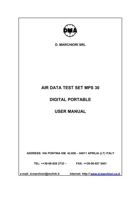
D. MARCHIORI SRL<br />
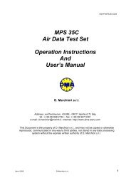
AIR DATA TEST SET MPS <strong>30</strong><br />
DIGITAL PORTABLE<br />
USER MANUAL<br />
ADDRESS: VIA PONTINA KM. 43.856 – 04011 APRILIA (LT) ITALY<br />
TEL: ++39-06-928 2733 – FAX: ++39-06-927 5401<br />
e-mail: d.marchiori@mclink.it Internet: http:// www.d.marchiori.co.it.
MPS <strong>30</strong> User’s Manual DMMC/0803/CM<br />
INDEX<br />
1.0 INTRODUCTION.............................................................................................................................................4<br />
2.0 GENERAL INFORMATION..........................................................................................................................4<br />
3.0 MAIN PARTS.....................................................................................................................................................4<br />
4.0 TECHNICAL DATA.........................................................................................................................................5<br />
4.1 AIR DATA FUNCTIONS........................................................................................................................................5<br />
4.2 ADDITIONAL FEATURES.......................................................................................................................................6<br />
4.3 ACCURACY........................................................................................................................................................7<br />
4.4 POWER SUPPLY REQUIREMENT.............................................................................................................................7<br />
4.5 INTERFACES ......................................................................................................................................................8<br />
4.6 DIMENSIONS......................................................................................................................................................8<br />
4.7 ENVIRONMENTAL................................................................................................................................................8<br />
4.8 <strong>CALIBRATION</strong>.....................................................................................................................................................8<br />
4.9 SELF-TEST TIME AT STARTUP..............................................................................................................................8<br />
4.10 OPTIONS.........................................................................................................................................................8<br />
4.11 COMMAND AND CONTROL..................................................................................................................................9<br />
4.12 CONTROL CAPABILITY WITH INTERNAL PUMPS.....................................................................................................9<br />
4.13 PROTECTION TO AVOID DAMAGE TO THE INSTRUMENT.......................................................................................... 9<br />
4.14 PROTECTION AGAINST ELECTRICAL POWER LOSS................................................................................................11<br />
5.0 EQUIPMENT DESCRIPTION.....................................................................................................................12<br />
5.1 FRONT PANEL..................................................................................................................................................12<br />
6.0 DESCRIPTION OF THE HHRCU.............................................................................................................14<br />
6.1 DISPLAY.........................................................................................................................................................14<br />
6.2 KEYBOARD......................................................................................................................................................14<br />
7.0 STARTUP..........................................................................................................................................................17<br />
8.0 OPERATION....................................................................................................................................................19<br />
8.1 ENTERING ALTITUDE AND AIRSPEED VALUES.......................................................................................................19<br />
8.1.1 Direct Entry...................................................................................................................................19<br />
8.1.2 Stepping by Using Arrow Keys.......................................................................................................19<br />
8.2 ENTERING PRESSURE VALUES.............................................................................................................................20<br />
8.3 CHANGING PRESET LIMITS WITH THE LIMITS MENU..............................................................................................21<br />
8.3.1 Access to the Limits Menu..............................................................................................................21<br />
8.3.2 Changing Values in the Limits Menu.............................................................................................21<br />
8.3.3 Changing Units of Measurement....................................................................................................23<br />
8.4 AMBIENT MEASUREMENT/PAUSE MODE/PANIC BUTTON.......................................................................................24<br />
8.5 LEAK TEST.....................................................................................................................................................25<br />
8.5.1 Automatic Leak Test.......................................................................................................................25<br />
8.5.2 GO/NO GO Leak Test Procedure...................................................................................................26<br />
8.6 VENT FUNCTION............................................................................................................................................27<br />
8.7 ENGINE PRESSURE RATIO (EPR).......................................................................................................................27<br />
8.8 MACH NUMBER...............................................................................................................................................28<br />
8.9 CENTER LINE CORRECTION................................................................................................................................29<br />
8.10 TRUE AIRSPEED.............................................................................................................................................29<br />
8.11 VERY LOW AIRSPEED CONTROL.......................................................................................................................29<br />
8.12 “CONTROL LOSS” FUNCTION...........................................................................................................................<strong>30</strong><br />
8.13 “ENHANCED RESOLUTION FUNCTION”...............................................................................................................<strong>30</strong><br />
9 PROGRAMMING MPS<strong>30</strong>.................................................................................................................................31<br />
9.1 EXAMPLE: PROGRAMMING THE MPS<strong>30</strong> ACCORDING THE FAR 43, APPENDIX E......................................................35<br />
10.0 VALVE CONTROL ADJUSTMENT........................................................................................................39<br />
11.0 SUGGESTIONS FOR THE GROUND PROXIMITY WARNING SYSTEM TEST........................40<br />
Issue Aug. 03 D. Marchiori PROPRIETARY INFORMATION - 2<br />
This material not to be disclosed or reproduced.
MPS <strong>30</strong> User’s Manual DMMC/0803/CM<br />
12.0 MULTIPLE ISOLATOR CONTROL (OPTION)...................................................................................40<br />
13.0 CONTROLLING MPS<strong>30</strong> WITH A PC (OPTION).................................................................................41<br />
14.0 TESTING AND CALIBRATING MPS<strong>30</strong> WITH A PC AND PAMB 5 TSDT (OPTION)................41<br />
15.0 <strong>CALIBRATION</strong>..............................................................................................................................................43<br />
15.1 ZERO CORRECTION.......................................................................................................................................43<br />
15.2 GAIN CORRECTION.......................................................................................................................................44<br />
16.0 USE OF AN EXTERNAL VACUUM PUMP............................................................................................46<br />
17.0 429 BUS DATA DISPLAY (ARINC OPTION).........................................................................................46<br />
18.0 ENCODING ALTIMETER READING (OPTION).................................................................................47<br />
19.0 TROUBLE SHOOTING AND MAINTENANCE SUGGESTIONS.....................................................48<br />
19.1 TEST FOR PNEUMATIC LEAKAGE AND REPAIR.....................................................................................................48<br />
19.2 CLEANING OF THE PUMP’S VALVES..................................................................................................................49<br />
19.3 MPS<strong>30</strong> TERMINAL CONFIGURATION................................................................................................................49<br />
Issue Aug. 03 D. Marchiori PROPRIETARY INFORMATION - 3<br />
This material not to be disclosed or reproduced.
1.0 INTRODUCTION<br />
MPS <strong>30</strong> User’s Manual DMMC/0803/CM<br />
MPS <strong>30</strong><br />
PORTABLE DIGITAL AIR DATA TEST SET<br />
USER’S MANUAL<br />
The procedures for using and calibrating the MPS <strong>30</strong> Portable Digital Air Data<br />
Test Set (ADTS) manufactured by D. Marchiori s.r.l, Italy are contained in this<br />
<strong>manual</strong>.<br />
2.0 GENERAL INFORMATION<br />
The MPS <strong>30</strong> is a <strong>portable</strong> <strong>test</strong> <strong>set</strong> ideal for measuring and controlling the<br />
pressures related to altitude and <strong>air</strong>speed and their rates of change. These values<br />
may be displayed in <strong>air</strong> <strong>data</strong> units or engineering units.<br />
The MPS <strong>30</strong> is remotely controlled, with a lightweight, sealed, shockproof control<br />
unit with a 20 m extension cable. The control unit, to be carried aboard the <strong>air</strong>craft, is<br />
resistant to shocks received during a free fall of 2 m and is shielded against<br />
electromagnetic interference (EMI), according to FCC, Class A, Part 15.<br />
3.0 MAIN PARTS<br />
The MPS <strong>30</strong> (shown in Figure 3-1) can be logically divided into six operating<br />
subsystems:<br />
• Static pneumatic circuitry<br />
• Pitot pneumatic circuitry<br />
• Internal compressor/vacuum generators<br />
• Microprocessor and electronics to read and control the pressures<br />
• Very accurate resonant pressure transducers to measure pressures<br />
• Hand-held remote control unit (HHRCU) to control functions and display<br />
the parameters.<br />
Issue Aug. 03 D. Marchiori PROPRIETARY INFORMATION - 4<br />
This material not to be disclosed or reproduced.
4.0 TECHNICAL DATA<br />
4.1 Air Data Functions<br />
MPS <strong>30</strong> User’s Manual DMMC/0803/CM<br />
The MPS <strong>30</strong> generates the following <strong>air</strong> <strong>data</strong> <strong>test</strong> outputs:<br />
• Altitude in various units.<br />
• Static pressure in various units.<br />
• Air speed in various units.<br />
• Total pressure in various units.<br />
• Simultaneous altitude and <strong>air</strong>speed.<br />
• Vertical speed (ft/min) or Airspeed Rate (kt/min)<br />
• Mach number.<br />
• True <strong>air</strong>speed calculation.<br />
• Engine pressure ratio (EPR or Ptot/Pstat).<br />
Figure 4-1 - MPS <strong>30</strong> Air Data Test Set<br />
Issue Aug. 03 D. Marchiori PROPRIETARY INFORMATION - 5<br />
This material not to be disclosed or reproduced.
4.2 Additional Features<br />
The following functions and features are provided:<br />
MPS <strong>30</strong> User’s Manual DMMC/0803/CM<br />
• Leakage <strong>test</strong>. Using the LEAK key of the HHRCU, leakage is<br />
automatically measured in the desired engineering units per minute. The<br />
condition before the leakage <strong>test</strong> is restored, by pushing the Resume key.<br />
This function, also running with the multiple Isolator part number MPS<br />
<strong>30</strong>EMI (Optional) can separately control up to four Static and four Pitot<br />
lines in various combinations.<br />
• Vent function. At the end of the instruments <strong>test</strong>, this function<br />
automatically brings the static and pitot lines back quickly but safely to the<br />
atmospheric pressure. When the safe condition is reached, the control<br />
unit LCD reads Test Set and can be disconnected.<br />
• Selectable units: with the SET key of the Control Unit<br />
- For altitude: feet and meters.<br />
- For pressure: in Hg, hPa, Pa, mmHg, and psi.<br />
- For speed: kt, m.p.h. and km/h.<br />
• Center line correction. To input the altitude difference between the <strong>test</strong> <strong>set</strong><br />
and unit under <strong>test</strong> (UUT).<br />
• Programmability of the <strong>test</strong>. The <strong>test</strong>s can be made <strong>manual</strong>ly by typing<br />
the desired altitude, <strong>air</strong>speed, and vertical speed values with the<br />
keyboard or in two other ways: with pre-defined steps, or with 25<br />
complete pre<strong>set</strong> <strong>test</strong> profiles.<br />
• Vacuum generation. May be used to fasten special adapters with suckers<br />
to the <strong>air</strong>craft.<br />
• Limit values at startup: The ADTS is easily programmable for limit (not to<br />
exceed) values of the altitude, speed, vertical speed, Mach number, and<br />
speed ratio. The MPS <strong>30</strong> is delivered with the following pre<strong>set</strong> values<br />
from the factory:<br />
- Minimum altitude: –1,500 ft.<br />
- Maximum altitude: 50,000 ft.<br />
- Maximum <strong>air</strong>speed: 450 kt.<br />
- Maximum vertical speed: 6,000 ft/min.<br />
- V/t (IAS ratio): <strong>30</strong>0 kt/min.<br />
- Max Mach no.: 1<br />
The <strong>user</strong> can change these values. The <strong>test</strong> <strong>set</strong> can be furnished, upon<br />
request, with different default values.<br />
- Units of measurement at startup: feet, knots, inHg.<br />
• Automatic Protection against excessive leakage in Pitot line, running also<br />
with large Pitot volumes.<br />
Issue Aug. 03 D. Marchiori PROPRIETARY INFORMATION - 6<br />
This material not to be disclosed or reproduced.
4.3 Accuracy<br />
• Altitude:<br />
MPS <strong>30</strong> User’s Manual DMMC/0803/CM<br />
- Range: –2,000 to +85,000 ft (65000 ft with the internal pump).<br />
- Measuring accuracy: ±3 ft @ sea level with reference to the primary<br />
standard<br />
- Resolution: 1 ft<br />
- Generated signal stability: 3 ft @ 20,000 ft without leakage<br />
• Vertical speed:<br />
- Range: 0 to <strong>30</strong>,000 ft/min, the maximum value can be lowered with<br />
keyboard<br />
- Accuracy of the vertical speed generation: 50 ft/min or 2% of the <strong>set</strong><br />
value, whichever is greater<br />
• Airspeed:<br />
- Range: 10 to 800 kt, with internal pump.<br />
- Reading accuracy: 0.4 kt @ 150 kt<br />
- Resolution: 0.1 kt over 50 kts, 1 kt from 20 to 50 kt<br />
- Stability: 0.2 kt @ 500 kt (0.01 in Hg)<br />
- Generated <strong>air</strong>speed rate. Default is 150 kt/min, can be <strong>set</strong> with<br />
keyboard up to 500 kt/min<br />
• Airspeed rate:<br />
- Range: 0 to 900 kt/min, the pre<strong>set</strong> value is <strong>30</strong>0 kt/min; value can be<br />
chenged with keyboard<br />
• EPR (generation). The engine pressure ratio values are generated<br />
referenced to static pressure in inHg. In this function, the default limit<br />
Mach Number and Airspeed are not considered:<br />
- Range: 0 to 2.5 @ s.l (raises if altitude increases).<br />
- Accuracy: 0.002 @ s.l.<br />
- Resolution: 0.001 @ s.l.<br />
• Mach number:<br />
• Range: 0.200 to 4.000<br />
• Accuracy: 0.002 Mach @ s.l.<br />
• Resolution: 0.001 Mach<br />
• Repeatability: 0.001 Mach<br />
4.4Power Supply Requirement<br />
It is possible to connect the ADTS to power supply sources ranging from 115 to<br />
220 Vac, from 50 to 400 Hz, 160 W<br />
Issue Aug. 03 D. Marchiori PROPRIETARY INFORMATION - 7<br />
This material not to be disclosed or reproduced.
4.5Interfaces<br />
RS 232C can be supplied as option.<br />
IEEE-488 can be supplied as option.<br />
ARINC 429 can be supplied as option<br />
MIL-1553 can be supplied as option<br />
4.6Dimensions<br />
• Size: 20 in. � 16 in. ��12 in.<br />
• Weight: 60 LB<br />
4.7Environmental<br />
• Storage temperature: –20 to +70 °C<br />
• Operating temperature: 0 to +40 °C<br />
MPS <strong>30</strong> User’s Manual DMMC/0803/CM<br />
• Sealing. Case and HHRCU splash and rain sealed<br />
4.8Calibration<br />
• Completely performed via internal software through the HHRCU keyboard<br />
(first-level calibration).<br />
• Recoverable error for static and pitot pressure. Without any limitation, it is<br />
advisable to send the <strong>test</strong> <strong>set</strong> to the manufacturer for an error bigger than<br />
2 mbar.<br />
• Self-reconditioning of the control valves is accomplished via internal<br />
software, when required to regulate the control parameters of the flow<br />
regulators. This operation may be required after long running periods of<br />
the <strong>test</strong> <strong>set</strong> to re-adapt the software control parameters to the aging of the<br />
pressure control valves.<br />
4.9Self-Test Time at Startup<br />
Automatic self-<strong>test</strong> is initiated at power-on. The MPS <strong>30</strong> is ready for operation in<br />
about 60 seconds after power-on.<br />
4.10 Options<br />
• Low-voltage power supply section, 22÷<strong>30</strong> Vdc (in addition with the<br />
110÷240 Vac 48÷440 Hz) .<br />
• Multiple isolator (separation box, pneumatically sealed, to directly<br />
perform, from the control unit, leakage <strong>test</strong>s on four separate static and<br />
four separate pitot lines, without repositioning the pipes or hoses).<br />
• Readout of the binary code generated by the encoding altimeters.<br />
• Software package to connect the ADTS to a PC/AT-compatible computer<br />
to perform special <strong>test</strong> profiles and to record and print the <strong>test</strong> results<br />
(suitable for laboratory operation and to record the <strong>test</strong>), connecting cable<br />
(supplied).<br />
Issue Aug. 03 D. Marchiori PROPRIETARY INFORMATION - 8<br />
This material not to be disclosed or reproduced.
MPS <strong>30</strong> User’s Manual DMMC/0803/CM<br />
• Software package to automatically calibrate and <strong>test</strong> the ADTS with a<br />
compatible computer and a special transfer standard P/N PAMB 5;<br />
connecting cables supplied<br />
• IEEE 488 interface.<br />
• RS232 interface<br />
4.11 Command and Control<br />
The lightweight (12-oz) HHRCU has 32 low-profile keys, and a backlit LCD<br />
display with three menus as shown in Figure 4-1:<br />
• Operational menu, shows the target values and the actual ones, plus the<br />
units of measurement.<br />
• Limits menu, used to <strong>set</strong> the maximum and minimum parameters<br />
according to the system under <strong>test</strong>, to <strong>set</strong> the speed (indicated <strong>air</strong> speed<br />
(IAS)) variation, and to define the steps AL, AS, and AR to be used during<br />
the <strong>test</strong>.<br />
• Profiles menu, used to insert the values of the pre<strong>set</strong> <strong>test</strong> profiles.<br />
• A excludible beep notifies the operator of the achievement of the target<br />
values.<br />
4.12 Control Capability with Internal Pu<strong>mps</strong><br />
The control capability is optimized for the following loads; for special<br />
requirements, the MPS <strong>30</strong> can be modified for larger volumes:<br />
• Static line—With 500 cu in. (8.2 liters), the vertical speed can be<br />
controlled at 6,000 ft/min up to 50,000 ft.<br />
• Pitot line—The maximum limit speed can be stabilized with a volume of<br />
200 cu in. (3.28 liters).<br />
4.13 Protection to Avoid Damage to the Instrument<br />
• Hardware—Intrinsically safe, the electrovalves, normally closed without<br />
electrical power, prevent <strong>air</strong>flow, and do not generate Ps > Pt. Also, the<br />
<strong>manual</strong> regulators do not generate Ps > Pt.<br />
• Software—In any case, the above condition is not allowed.<br />
• Software limitations—<br />
- Max altitude.<br />
- Max <strong>air</strong>speed.<br />
- Max vertical speed.<br />
- Airspeed rate.<br />
- Max Mach number<br />
(Note: Airspeed and Mach number always interact. It is, therefore,<br />
impossible to overcome the maximum value of one or the other.)<br />
Issue Aug. 03 D. Marchiori PROPRIETARY INFORMATION - 9<br />
This material not to be disclosed or reproduced.
MPS <strong>30</strong> User’s Manual DMMC/0803/CM<br />
- Software protections—If <strong>data</strong> entered are larger than softwareimposed<br />
limitations, the ADTS continues and controls the pressures<br />
according to the imposed limitations.<br />
Figure 4-2 Layout of the HHRCU<br />
Issue Aug. 03 D. Marchiori PROPRIETARY INFORMATION - 10<br />
This material not to be disclosed or reproduced.
4.14 Protection against Electrical Power Loss<br />
MPS <strong>30</strong> User’s Manual DMMC/0803/CM<br />
In case of electrical power surge, nothing happens to the lines under <strong>test</strong>. When<br />
the electric power comes back, the ADTS senses the pressure in the lines and<br />
forces the control system to equalize the measured ones (if altitude are > 8000<br />
feet). Pitot and static lines can be <strong>manual</strong>ly discharged using two flow control<br />
regulators placed in the front of the <strong>test</strong> <strong>set</strong>. The <strong>manual</strong> discharge operation does<br />
not generate pitot negative pressure, or <strong>air</strong>speed exceeding the value <strong>set</strong> by an<br />
internal pneumatic pressure-flow regulator.<br />
Issue Aug. 03 D. Marchiori PROPRIETARY INFORMATION - 11<br />
This material not to be disclosed or reproduced.
5.0EQUIPMENT DESCRIPTION<br />
5.1Front Panel<br />
MPS <strong>30</strong> User’s Manual DMMC/0803/CM<br />
Two pressure ports (or more in case of Multiple Isolator) on the front panel as<br />
shown in Figure 5-1 provide connections to the <strong>air</strong>craft pressure ports. No. 9 is for<br />
the static and No. 10 is for the pitot port. The diameters of the two quick-disconnect<br />
couplers are different sizes to avoid wrong connections. As option the ports can be 4<br />
(or 2, or 3) static and 4 (or 2, or 3) pitot, connected to normally open valves that can<br />
be open/close through the HHRCU to verify leakage.<br />
Manual regulators (3 and 4) are used to vent the system in case of electrical<br />
power interruption. If the electrical power failure continues, <strong>manual</strong>ly open (slowly,<br />
counter-clockwise) regulators 3 and 4 together, be sure the “V” No. 3 does not cause<br />
an excessive <strong>air</strong>speed, and the “E” No. 4 does not cause an excessive altitude rate.<br />
If the ADTS has been <strong>manual</strong>ly vented before the startup, close the needle<br />
valves before switching-on.<br />
Connections to external pressure/vacuum generators must be tightly closed<br />
(fittings 5 and 6 of Figure 5-1).<br />
Fitting 5 is the positive pressure port, and may be used to apply a positive<br />
pressure, not exceeding 2,000 hPa (relative). This may be used if the internal<br />
pressure generator of the MPS <strong>30</strong> is not adequate for the pitot load.<br />
Fitting 6 is the vacuum port. It may also be used as a vacuum source to fasten<br />
special adapters with suckers to the <strong>air</strong>craft (sometimes used for the static port).<br />
This port may be used to connect an external vacuum pump to the MPS <strong>30</strong> to<br />
replace the internal one.<br />
Electrical connectors, switches, and warning lights:<br />
- Connection to the electrical power: No. 2.<br />
- Connection to the HHRCU: No. 7.<br />
- Connection for remote control RS232 (optional) No. 8. This connector may be<br />
used to control all the functions with an external PC with high level instructions.<br />
Powerful for use of MPS<strong>30</strong> in ATE systems.<br />
Issue Aug. 03 D. Marchiori PROPRIETARY INFORMATION - 12<br />
This material not to be disclosed or reproduced.
MPS <strong>30</strong> User’s Manual DMMC/0803/CM<br />
1. "On/Off" Switch 9. Static Port<br />
2. Power Connector 10. Pitot Port<br />
2. Pitot Vent needle Valve 11. Labyrinth pressure equalizer<br />
4. Cross bleed needle Valve 12. Water extraction button<br />
5. External Pressure Port 13. 4A Fuse<br />
6. External Vacuum Port 14. Power On LED<br />
7. HHRCU Connector 15. Encoding altimeters connector(opt.)<br />
8. RS232 Port for PC remote control<br />
Figure 5-1 MPS <strong>30</strong> Front Panel<br />
Issue Aug. 03 D. Marchiori PROPRIETARY INFORMATION - 13<br />
This material not to be disclosed or reproduced.
6.0 DESCRIPTION OF THE HHRCU<br />
MPS <strong>30</strong> User’s Manual DMMC/0803/CM<br />
The HHRCU is composed of two parts: the keyboard and the LCD.<br />
6.1 Display<br />
The writings on the frame surrounding the LCD are valid only for the Operation<br />
mode. The first line, starting from the upper position, is the line of the measured<br />
values. The second line is the line of the target (<strong>set</strong>) values. The third line is for<br />
pressures (static, pitot, and total). The bottom line shows the Pt/Ps ratio, for the<br />
Mach number and for the unit of measure in use. The columns of the first three lines<br />
are for altitude, <strong>air</strong>speed, and altitude rate, respectively.<br />
The four-rows, 20 columns alphanumeric LCD is back-lighted and supports “no<br />
light”, plus four levels of back light intensity. Figure 6-1 shows the HHRCU display in<br />
the operational mode.<br />
6.2 Keyboard<br />
Starting from the top line, the keys are laid out as follows (see diagram or the<br />
HHRCU):<br />
• The LCD UP ARROW key (�) (upper left, first row) to increase the LCD<br />
backlighting intensity level.<br />
• The LCD DOWN ARROW key (�) (upper right, first row) to decrease the<br />
LCD backlighting intensity level.<br />
• AL, AS, and AR, respectively, are for altitude, <strong>air</strong>speed, and altitude rate.<br />
These keys are used before the numeric keys to <strong>set</strong> the desired values.<br />
• The SET key to change the measurement unit.<br />
• The VENT key to re<strong>set</strong> the ambient pressure in the static and pitot<br />
circuits, to safely disconnect the <strong>test</strong> lines from the <strong>air</strong>craft at the end of<br />
the <strong>test</strong>.<br />
• The LEFT ARROW key (�)to delete the last digit entered, if it is wrong.<br />
• The MEM key to store <strong>data</strong> inside the MPS <strong>30</strong> memory.<br />
• The LEAK key to automatically perform the leak <strong>test</strong> without a stopwatch.<br />
RESUME, written in red at the upper right of the key, is used to restore<br />
the previous condition and must be used after the RED SHIFT.<br />
• The MENU key to switch from the Operative display to the Limits display.<br />
• The MEAS key to stop the control of pressure for measuring the<br />
parameters without the interference of the pressure control system. This<br />
key may be considered the “panic button” to quickly stop the operation of<br />
the unit.<br />
Issue Aug. 03 D. Marchiori PROPRIETARY INFORMATION - 14<br />
This material not to be disclosed or reproduced.
MPS <strong>30</strong> User’s Manual DMMC/0803/CM<br />
• The minus key (–) to <strong>set</strong> negative altitudes (static pressure higher than<br />
the ambient).<br />
• The point key (.) to input decimal points for speed and EPR.<br />
ALTITUDE AIRSPEED<br />
RATE<br />
READ READ<br />
SET SET<br />
PRESS PRESS<br />
VENT<br />
MENU<br />
CTRL<br />
MEAS<br />
-<br />
Pt/Ps<br />
MACH<br />
AL AS AR<br />
F1 Fa<br />
1<br />
F4 Fd<br />
4<br />
F7 Fg<br />
7<br />
PROGEXEC<br />
DEFAULT<br />
GO<br />
MEM<br />
F2 Fb<br />
2<br />
F5 Fe<br />
5<br />
F8 Fh<br />
8<br />
F0 Fz<br />
0<br />
RESUME<br />
LEAK<br />
F3 Fc<br />
3<br />
F6 Ff<br />
6<br />
F9 Fi<br />
9<br />
AL AS AR<br />
NORM<br />
EPR<br />
.<br />
UNITS<br />
SET<br />
Figure 6-1 HHRCU Display in Operational Mode<br />
Issue Aug. 03 D. Marchiori PROPRIETARY INFORMATION - 15<br />
This material not to be disclosed or reproduced.
MPS <strong>30</strong> User’s Manual DMMC/0803/CM<br />
• The numeric keys (0–9/F0–9) to <strong>set</strong> the desired values of the controlled<br />
parameters when used with RED or BLUE SHIFT functions, F0–F9.<br />
(Note: Some of the “F” legends on the upper position of the numeric keys<br />
are not used and can be programmed for custom requirements.)<br />
• The UP triangle key (▲) to increase, by a pre-programmed step, the<br />
different parameters (AL, AS, and AR).<br />
• The DOWN triangle key (▼) to decrease, by a pre-programmed step, the<br />
different parameters (AL, AS, and AR).<br />
• The PROG/EXEC/DEFAULT key for programming functions. PROGram is<br />
used for entering the programming mode, EXECute to initiate the<br />
program, and DEFAULT for returning to the operational mode.<br />
• The AL, AS, AR (UP/DOWN ARROW) key is used before the previous<br />
key to establish the parameter that must be changed.<br />
• The BLUE SHIFT key ( ) to activate the upper-left functions on the keys,<br />
marked in blue.<br />
• The RED SHIFT key ( ) to activate the upper-right functions on the keys,<br />
marked in red.<br />
• The GO/ENTER key (↵) to input the desired <strong>data</strong> to the MPS <strong>30</strong>.<br />
• The EPR/NOR key to generate a total pressure/static pressure ratio<br />
starting from the desired altitude. The blue upper-left NOR on this key is<br />
used to re<strong>set</strong> the NORmal <strong>air</strong> <strong>data</strong> operation, when used with BLUE<br />
SHIFT.<br />
Issue Aug. 03 D. Marchiori PROPRIETARY INFORMATION - 16<br />
This material not to be disclosed or reproduced.
7.0 STARTUP<br />
MPS <strong>30</strong> User’s Manual DMMC/0803/CM<br />
NOTE<br />
For safe operation, the MPS <strong>30</strong> must be<br />
placed with the front panel face up. The<br />
internal vibrating cylinders are slightly<br />
sensitive to gravity. Operation with the front<br />
panel face up is required for precision<br />
readings. Before switching ON the MPS <strong>30</strong><br />
and connecting it to altitude and <strong>air</strong>speed<br />
ports it must be at ambient pressure. Press<br />
VENT and connect instruments only after<br />
TEST BENCH CAN BE DISCONNECTED<br />
appears. Remember also to close<br />
completely the needle valves before starting<br />
the <strong>test</strong>.<br />
For normal operation, perform the following steps:<br />
1. Connect the HHRCU cable to connector 7 on the front panel. If necessary,<br />
use the 50-ft extension cable included.<br />
2. Switch the power switch 1 - ON.<br />
3. After the start-up button is pressed, the MPS <strong>30</strong> Air Data Test Set begins<br />
its startup and self-check routine. This routine will take approx. 1 minute.<br />
During this period, the following information are displayed:<br />
• Serial number of the ADTS<br />
• Embedded software issue<br />
• Operation time in hours<br />
• Last calibration date<br />
After the self-check routine is over, the MPS <strong>30</strong> will measure the ambient<br />
conditions in the pitot and static ports (or <strong>test</strong> lines, if connected).<br />
If the altitude sensed in the static line is lower than 8,000 ft, the MPS <strong>30</strong> will<br />
automatically impose the VENT function. When the normal start-up<br />
process is over, the reading “TEST SET CAN BE DISCONNECTED” will<br />
appear. When this occurs, press RETURN/GO (↵) to enter the<br />
Operational mode.<br />
Issue Aug. 03 D. Marchiori PROPRIETARY INFORMATION - 17<br />
This material not to be disclosed or reproduced.
MPS <strong>30</strong> User’s Manual DMMC/0803/CM<br />
4. Connect the static 9 and pitot 10 pneumatic lines to the relevant <strong>air</strong>craft or<br />
instruments ports.<br />
If ambient altitude in the static line is higher than 8,000 ft, the following conditions<br />
will be automatically <strong>set</strong>: the <strong>set</strong> Airspeed will be adjusted to the same value<br />
measured in the pitot line, the Set Altitude will be adjusted to the value measured in<br />
the static line, the Set AL Rate will become 3,000 ft/min, and the VENT function will<br />
not be imposed.<br />
A repetitive “beep-beep” is used to signal that the target condition has been<br />
achieved. Use the BLUE SHIFT/F2 function keys to turn the “beep” feature on / off.<br />
If a power loss condition occurs and <strong>manual</strong> venting is required due to pressure<br />
in the <strong>test</strong> lines, this can be accomplished by opening the two needle valves (X and<br />
Y, Figure 5-1). Be sure the valves are closed after venting is over.<br />
Issue Aug. 03 D. Marchiori PROPRIETARY INFORMATION - 18<br />
This material not to be disclosed or reproduced.
8.0 OPERATION<br />
8.1 Entering Altitude and Airspeed Values<br />
8.1.1 Direct Entry<br />
MPS <strong>30</strong> User’s Manual DMMC/0803/CM<br />
To enter an altitude, press the AL key (on the upper row) and enter the desired<br />
altitude value using the keypad. After entering the desired value, press the<br />
RETURN/GO key. The required altitude is now entered in the MPS <strong>30</strong>, but it will not<br />
be reached until an altitude rate greater than 0 is entered. To add an altitude rate<br />
value, press the AR key, then enter the numbers of the desired altitude rate with the<br />
keypad followed by pressing the RETURN/GO key.<br />
To enter the exact <strong>air</strong>speed, press the AS key followed by the desired <strong>air</strong>speed<br />
in knots, then press the RETURN/GO key. When the <strong>air</strong>speed value is entered, the<br />
MPS <strong>30</strong> will <strong>set</strong> off toward the target values.<br />
The pre<strong>set</strong> <strong>air</strong>speed rate is <strong>30</strong>0 kt/min. To visualize the pre<strong>set</strong> <strong>air</strong>speed, press<br />
the BLUE SHIFT key, followed by AR key: the K(nots) letter and the pre<strong>set</strong> <strong>air</strong>speed<br />
rate value will appear in the <strong>set</strong> rate sector of HHRCU, in place of altitude rate. To<br />
change the <strong>air</strong>speed pre<strong>set</strong> value, press the AR key and <strong>set</strong> the new value using<br />
numerical keys, followed by RETURN/GO key.<br />
To return to altitude rate, press again BLUE SHIFT key, followed by AR key.<br />
8.1.2 Stepping by Using Arrow Keys<br />
This method is a quick one for <strong>set</strong>ting altitude and rate parameters using pre-<br />
determined altitude steps and UP ARROW or DOWN ARROW keys. The step can<br />
be programmed with custom step values, or factory pre<strong>set</strong> default values can be<br />
used.<br />
To step the target altitude, press UP/DOWN ARROW AL key, followed by the<br />
UP ARROW key if the altitude must be increased, or by the DOWN ARROW key if<br />
the altitude value must be decreased.<br />
To change the altitude rate by stepping, press UP/DOWN ARROW AR key<br />
followed by the UP ARROW or the DOWN ARROW to increase or decrease the<br />
desired <strong>set</strong>ting.<br />
To change the <strong>air</strong>speed by stepping, press UP/DOWN ARROW AS key followed<br />
by the UP ARROW or the DOWN ARROW to increase or decrease the desired<br />
<strong>set</strong>ting.<br />
Issue Aug. 03 D. Marchiori PROPRIETARY INFORMATION - 19<br />
This material not to be disclosed or reproduced.
MPS <strong>30</strong> User’s Manual DMMC/0803/CM<br />
For all functions, holding UP ARROW or DOWN ARROW key will make a<br />
continuous increase or decrease by the defined step until the key is released.<br />
Note that the last UP/DOWN ARROW key function selected is always valid for<br />
the UP ARROW or DOWN ARROW function. For example, if a step of 500 has been<br />
entered and an altitude of 4,500 ft has been reached using this method, to pass to<br />
the altitude of 5,000 ft, the UP ARROW key has only to be pressed once to generate<br />
another 500-ft step.<br />
8.2 Entering pressure Values<br />
Pressure values can be entered for static and pitot lines in the required<br />
engineering units: The total pressure must always be higher than the static one.<br />
To enter a static pressure (in the unit of measure displayed), press the "Blue<br />
Shift” key (left shift) followed by “AL” key, then insert the numeric values of the<br />
requested pressure.<br />
To enter a differential pressure (in the displayed unit of measure), press the<br />
"Blue Shift” key (left shift) followed by “AS” key, then insert the numeric values of the<br />
requested pressure.<br />
To enter a total pressure (in the displayed unit of measure), press the "Red Shift”<br />
key (right shift) followed by “AS” key, then insert the numeric values of the requested<br />
pressure.<br />
Issue Aug. 03 D. Marchiori PROPRIETARY INFORMATION - 20<br />
This material not to be disclosed or reproduced.
8.3 Changing Pre<strong>set</strong> Limits with the Limits Menu<br />
MPS <strong>30</strong> User’s Manual DMMC/0803/CM<br />
CAUTION<br />
Limits are pre<strong>set</strong> at the factory to handle<br />
most <strong>test</strong> standard conditions and to protect<br />
most <strong>air</strong>craft instrumentation. The operator<br />
should use extreme care and caution in<br />
<strong>set</strong>ting limits outside normal operation<br />
ranges and when operating the MPS <strong>30</strong><br />
under these limits. Damage to the units<br />
under <strong>test</strong> could occur if caution is not<br />
observed.<br />
The pre<strong>set</strong> limits will be <strong>set</strong> as follows:<br />
• ALMx is the maximum allowed altitude.<br />
• ALMi is the minimum allowed altitude.<br />
• ASMx is the maximum allowed <strong>air</strong>speed.<br />
• MaMx is the maximum allowed Mach number.<br />
• ARMx is the maximum allowed altitude/rate.<br />
• AS/m is the imposed variation of the <strong>air</strong>speed.<br />
• DA is the default step interval in feet used for the stepping function.<br />
• DS is the default step interval in knots used for the stepping function.<br />
• DR is the default step interval in ft/min used for the altitude rate function.<br />
To exit from the Limits Menu and to return to the Operation Menu, press the<br />
MENU key again.<br />
8.3.1 Access to the Limits Menu<br />
To gain access to the Limits menu, press the MENU key once. The LCD will<br />
display the pre<strong>set</strong> limits in the display as shown in Figure 8-1.<br />
8.3.2 Changing Values in the Limits Menu<br />
Once in the Limits Menu, to change the limits and the step values, press the SET<br />
key. A “>“ symbol will appear in front of the value to indicate the limit to be changed<br />
(ALMx). To change its value, insert with the numeric keys the new value followed by<br />
the RETURN/GO key. The new altitude limit will be displayed and the ”>“ symbol will<br />
shift to the next limit (ALMi). Press the RETURN/GO key to keep the old value and<br />
go to the next parameter, and so on.<br />
Issue Aug. 03 D. Marchiori PROPRIETARY INFORMATION - 21<br />
This material not to be disclosed or reproduced.
READ<br />
SET<br />
PRESS<br />
MPS <strong>30</strong> User’s Manual DMMC/0803/CM<br />
ALTITUDE AIRSPEED RATE<br />
ALMx 50000 ALMi -1500<br />
ASMx 450 MaMAx 1.00<br />
ARMx 6000 AS/m <strong>30</strong>0<br />
DA 500 DS 10 DR 500<br />
Pt/Ps MACH UNITS<br />
HHRCU in limits mode<br />
Figure 8-1 HHRCU in Limit Menu<br />
READ<br />
SET<br />
PRESS<br />
Proceed this way until all parameter values are <strong>set</strong> and the “>“ is no longer<br />
displayed. At this point, press the MENU key again and the MPS <strong>30</strong> will return to the<br />
Operations Menu. The new limits will automatically be used from MPS <strong>30</strong>.<br />
These new limits will be lost switching OFF the MPS<strong>30</strong>.<br />
To store the new limits as default, without switching the MPS <strong>30</strong> Off, when in<br />
normal control mode, press Fz, enter the CODE that is 0099.<br />
After the first parameter comes out, press GO (ENTER) many times (about 35<br />
times) until LSave is displayed.<br />
BE CAREFUL - DO NOT CHANGE any value of parameters that subsequently<br />
will appear, otherwise you COULD STOP THE MPS<strong>30</strong>. IF BY MISTAKE WRONG<br />
NUMBER(S) HAVE BEEN SET, SWITCH OFF THE MPS<strong>30</strong>, and ABSOLUTELY DO<br />
NOT PRESS “MEM” KEY.<br />
The LSave indicated number will be 0 (zero), enter 1 (one) and continue<br />
pressing GO (ENTER). When out of the Fine Tuning file, press twice MEM. The new<br />
limits are now stored in the non volatile memory of the MPS <strong>30</strong>. You can see this by<br />
switching Off and On the MPS <strong>30</strong> and check the limits after the new switching On.<br />
Issue Aug. 03 D. Marchiori PROPRIETARY INFORMATION - 22<br />
This material not to be disclosed or reproduced.
MPS <strong>30</strong> User’s Manual DMMC/0803/CM<br />
CAUTION<br />
If a unique value has been entered for a<br />
particular <strong>test</strong>, remember to re<strong>set</strong> the limits<br />
after <strong>test</strong>ing to factory or maintenance shop<br />
default values to avoid damage to the MPS<br />
<strong>30</strong> or <strong>air</strong>craft instrumentation.<br />
8.3.3 Changing Units of Measurement<br />
While in the Operations Menu, press the SET key. A “>“ symbol will appear<br />
before “Ft” (feet). To change to “mt” (meters), press the UP ARROW key followed by<br />
the RETURN/GO key and the “>“ will now move before the “kt” (knots) legend.<br />
To change to kilometers per hour, press the UP ARROW key; the “>“ will now<br />
move before the “Kh” legend. To change to miles per hour, press the UP ARROW<br />
key again; the “>“ will now move before the “Mh” legend. When the desired<br />
engineering unit for the speed is achieved, press the RETURN/GO key.<br />
At this point, the “>“ symbol will move in front of the “In” (inches of mercury or<br />
inHg); this is the engineering unit for the altitude, <strong>air</strong>speed, and for total pressure<br />
(Ptot). To change this parameter, press the UP ARROW key. The possible<br />
engineering units options are: “hp” for hectoPascal, “Pa” for Pascal, “in” for inches of<br />
mercury, “mm” for millimeters of mercury, and “pi” for pounds per square inch.<br />
After selecting the required engineering units, press RETURN/GO key and the<br />
“>“ symbol will disappear. This indicates that all parameters have been selected.<br />
Issue Aug. 03 D. Marchiori PROPRIETARY INFORMATION - 23<br />
This material not to be disclosed or reproduced.
MPS <strong>30</strong> User’s Manual DMMC/0803/CM<br />
8.4 Ambient Measurement/Pause Mode/Panic Button<br />
The MEAS/CTRL function is also used as a pause or “the panic button”.<br />
The MEAS/CTRL key toggles between measurement and control modes. When<br />
the MEAS/CTRL key is pressed, the MPS <strong>30</strong> stops controlling pressure and only the<br />
pressure measuring system is activated. The circuit under <strong>test</strong> is now completely<br />
isolated from the pressure generator and a precision measurement can be obtained<br />
when the line pressures in the system under <strong>test</strong> and the MPS <strong>30</strong> are stabilized.<br />
Whenever a precision measurement is required, especially if large volumes are<br />
involved, the MEAS/CTRL function should be used. The MEAS/CTRL can also be<br />
used as a “panic button” or pause control to halt operation of the MPS <strong>30</strong> and to give<br />
the operator time to investigate a situation.<br />
To select the Measurement mode from the Control mode, press the MEAS/CTRL<br />
key. When the MEAS/CTRL key is pressed, the HHRCU will show the display shown<br />
in Figure 8-2.<br />
To resume the previous control condition when the measuring action is over,<br />
press the BLUE SHIFT key in the lower left, followed by the MEAS/CTRL KEY<br />
(CTRL = Control). This will restore the MPS <strong>30</strong> to Control mode.<br />
After using the MEAS/CTRL function it is not necessary to restore the MPS <strong>30</strong> to<br />
the previous control state. Press MEAS/CTRL followed by the BLUE SHIFT followed<br />
by the MEAS/CTRL key again. The <strong>test</strong> <strong>set</strong> will stop the MEAS/CTRL control<br />
function and it will be possible to input new target values.<br />
READ<br />
SET<br />
PRESS<br />
ALTITUDE AIRSPEED RATE<br />
8001 100.0 0<br />
8000 MEAS MEAS<br />
752.7 16.3 768.9<br />
1.022 0.179 Ft Kt HP<br />
Pt/Ps MACH UNITS<br />
HHRCU in MEAS mode<br />
Figure 8-2 HHRCU in Measure Mode<br />
READ<br />
SET<br />
PRESS<br />
Issue Aug. 03 D. Marchiori PROPRIETARY INFORMATION - 24<br />
This material not to be disclosed or reproduced.
8.5 Leak Test<br />
8.5.1 Automatic Leak Test<br />
MPS <strong>30</strong> User’s Manual DMMC/0803/CM<br />
This function performs the leak <strong>test</strong> of the static and pitot lines using a built-in<br />
timing function generated by the internal computer quartz clock. Leak rates are<br />
calculated every second and are automatically reported in ft/min and kt/min on the<br />
Leak menu.<br />
Select the leak <strong>test</strong> function by pressing the LEAK/RESUME key. The HHRCU<br />
display in the Leak Test mode is shown in Figure 8-2.<br />
For the best measurement, wait until the HHRCU display has become stable.<br />
Then press the LEAK/RESUME key again to re<strong>set</strong> the clock after transition numbers<br />
have stabilized for a clean start of the leak <strong>test</strong>.<br />
NOTE<br />
It may take up to <strong>30</strong> seconds for the measured<br />
value to stabilize.<br />
To return to the prior menu, press the RED SHIFT key on the lower right of the<br />
keyboard, followed by the LEAK/RESUME key (this resumes the prior condition with<br />
action of the red RESUME function of the LEAK/RESUME key).<br />
READ<br />
SET<br />
PRESS<br />
ALTITUDE AIRSPEED RATE<br />
sec ALTRate ASPRate<br />
10 -15 -0.3<br />
754.0 15.3 769.3<br />
1.021 0.174 Ft Kt hP<br />
Pt/Ps MACH UNITS<br />
HHRCU in LEAK mode<br />
Figure 8-3 HHRCU in Leak Mode<br />
READ<br />
SET<br />
PRESS<br />
Issue Aug. 03 D. Marchiori PROPRIETARY INFORMATION - 25<br />
This material not to be disclosed or reproduced.
8.5.2 GO/NO GO Leak Test Procedure<br />
MPS <strong>30</strong> User’s Manual DMMC/0803/CM<br />
An automatic and programmable (Go/No Go) Leak Test procedure is available,<br />
i.e. both the initial <strong>test</strong> values and the <strong>test</strong> features can be programmed, and the <strong>test</strong><br />
is automatic. When the <strong>test</strong> is over, it shows if leaks on the static and pitot circuits –<br />
compatible with the maximum acceptable values are found. This procedures starts<br />
with Fc key (RED SHIFT + 3). The menu shows the <strong>set</strong>ting requirements, default<br />
values are already shown, following the table here below:<br />
Parameter Description Measure Units Value<br />
Stab. Time Parameters Stabilization Time seconds 60<br />
Total Time Total time (reading + stabilization) seconds 120<br />
AllwdFt/m. Allowable Static Loss Ft/min. 50<br />
Allwdkt/m. Allowable Pitot Loss Kt/min. 1<br />
@ Feet Quote to reach to start <strong>test</strong> Ft 10000<br />
With Ft/m Choose the rate Ft/min. 4000<br />
@ Knots Speed to reach to start <strong>test</strong> Kt 150<br />
KnLKl Choose the rate Kt/min. 100<br />
The driven menu shows some default values, with such values the operator can<br />
reach pre-<strong>set</strong> speed and quote from which – after the <strong>set</strong> stabilization time – start the<br />
measurements of the average losses, in the remaining period (total time –<br />
stabilization time). Press RETURN/GO key if default values match the desired ones,<br />
or insert in each box the required numeric value, followed by the RETURN/GO key.<br />
The <strong>test</strong> will be carried out automatically, as it is programmed, at the end it will<br />
show two average leak values – stressing possible excesses vs the admitted leaks<br />
(GO/NO GO TEST). To exit from the <strong>test</strong> – at any moment – press RETURN/GO<br />
key.<br />
Issue Aug. 03 D. Marchiori PROPRIETARY INFORMATION - 26<br />
This material not to be disclosed or reproduced.
8.6 VENT Function<br />
MPS <strong>30</strong> User’s Manual DMMC/0803/CM<br />
The VENT function is used to restore the <strong>test</strong> circuit to ambient pressure for safe<br />
disconnection of the adapters from the <strong>air</strong>craft or from the unit under <strong>test</strong>.<br />
After the VENT key is pressed from an altitude higher than 10,000 ft, the MPS<strong>30</strong><br />
automatically starts a dive rate of 3,000 ft/min, imposes an altitude of 10,000 ft, and<br />
<strong>set</strong>s the <strong>air</strong>speed to zero. When altitude of 10,000 ft is reached (or if VENT is<br />
pressed from an altitude lower than 10,000 ft), the MPS<strong>30</strong> measures the ambient<br />
pressure and puts the target value of the static line at the ambient pressure. When<br />
the proper conditions to disconnect the hoses are reached, the reading: “TEST SET<br />
CAN BE DISCONNECTED” is displayed.<br />
To start a new <strong>test</strong> sequence, press the RETURN/GO key to return to the<br />
Operations menu.<br />
8.7 Engine Pressure Ratio (EPR)<br />
The engine pressure ratio (i.e., Pt/Ps) measurement is carried out starting from<br />
the desired static pressure value in inHg.<br />
Start from a condition where AR is any value other than zero.<br />
Connect <strong>test</strong> connections according to the <strong>air</strong>craft maintenance <strong>manual</strong> and<br />
press the EPR key. The HHRCU display (shown in Figures 8-4 and 8-5) will prompt<br />
the operator to input the desired values of starting pressure and the desired ratio.<br />
Enter the relevant values to input the static pressure in Inches Hg, then the EPR.<br />
The MPS <strong>30</strong> will reach and maintain the required Pt/Ps value.<br />
To return to the normal mode, press the BLUE SHIFT followed by EPR.( the <strong>test</strong><br />
<strong>set</strong> returns to the normal mode using the BLUE SHIFT/NORmal function.)<br />
Issue Aug. 03 D. Marchiori PROPRIETARY INFORMATION - 27<br />
This material not to be disclosed or reproduced.
READ<br />
SET<br />
PRESS<br />
READ<br />
SET<br />
PRESS<br />
8.8 Mach Number<br />
MPS <strong>30</strong> User’s Manual DMMC/0803/CM<br />
ALTITUDE AIRSPEED RATE<br />
ENG. PRESS. RATIO<br />
Pst:<br />
EPR:<br />
Pt/Ps MACH UNITS<br />
HHRCU in EPR input mode<br />
Figure 8-4 HHRCU in EPR Input Mode<br />
ALTITUDE AIRSPEED RATE<br />
26275 321.8 0<br />
26274 EPR 6000<br />
10.500 5.250 15.750<br />
1.500 0.784 Ft Kt in<br />
Pt/Ps MACH UNITS<br />
Figure 8-5 HHRCU in EPR Control Mode<br />
READ<br />
SET<br />
PRESS<br />
READ<br />
SET<br />
PRESS<br />
Instead of an <strong>air</strong>speed value, the Mach Number can be entered as a control<br />
parameter. The procedure is the following: press BLUE SHIFT then the F0 (also the<br />
0, or zero key). After input of the desired Mach number, press RETURN/GO. The<br />
<strong>air</strong>speed corresponding to this Mach number at the previously <strong>set</strong> altitude is now<br />
shown in the SET line of the <strong>air</strong>speed.<br />
Issue Aug. 03 D. Marchiori PROPRIETARY INFORMATION - 28<br />
This material not to be disclosed or reproduced.
MPS <strong>30</strong> User’s Manual DMMC/0803/CM<br />
If another Mach Number at a different altitude must be entered, the same<br />
procedure can be followed, since the Mach number is only calculated and placed as<br />
target AS. Again, this must start from a condition where AR is other than 0.<br />
8.9 Center Line Correction<br />
If an altitude difference between the ADTS and the UUT is required, the BLUE<br />
SHIFT/F3 function key can be used for this purpose. If the altitude value of the UUT<br />
is above the ADTS, the correction value must be a positive integer.<br />
An “*” before the READ Altitude shows to the operator that the corrected altitude<br />
is being displayed.<br />
8.10 True Airspeed<br />
Use the BLUE SHIFT/F4 function key to input the temperature for the true<br />
<strong>air</strong>speed (TAS). A “T” before the Read Airspeed signals the operator that the TAS is<br />
indicated and not the IAS. To restore the IAS reading, press again the RED SHIFT/<br />
F4 function key.<br />
8.11 Very Low Airspeed control<br />
This function is useful when working with helicopters, where very low <strong>air</strong>speed<br />
(below <strong>30</strong> kts) must be generated and measured.<br />
The special function: F5 must be used: this function accurately calibrates the<br />
total pressure, equalizing it to the static one.<br />
To perform this function, follow this procedure:<br />
- vent the MPS <strong>30</strong> to ambient pressure,<br />
- when vented, leave the <strong>air</strong>speed to zero kts. and put the altitude rate (AR) to<br />
zero ft/min,<br />
- use a quick disconnect fitting open to ambient to put and maintain the static<br />
pressure port at ambient pressure,<br />
- operate the F5 function key: this will fully equalize the total pressure as the<br />
static one, thus permitting the generation and measurement of very low<br />
<strong>air</strong>speed,<br />
Issue Aug. 03 D. Marchiori PROPRIETARY INFORMATION - 29<br />
This material not to be disclosed or reproduced.
MPS <strong>30</strong> User’s Manual DMMC/0803/CM<br />
- after a few seconds, the total pressure will be exactly equal to the static one,<br />
the resolution increases and it will be possible to read <strong>air</strong>speed from 2 (two)<br />
kts.<br />
The readings have no decimal points from 2 to 20 kts (i.e. 4 kts), from 20 kts to<br />
the Max allowed AS, the readings have one decimal point (i.e. 22.4 kts).<br />
When very low <strong>air</strong>speed must be generated, it is suggested to leave the static<br />
port open to ambient with altitude rate (AR) regulated at zero and connect only pitot<br />
port at pitot UUT (unit under <strong>test</strong>) port.<br />
To exit this function, operate the Fg key.<br />
8.12 “Control Loss” Function<br />
This function shuts off the pressure control when the volume is too high to be<br />
emptied or filled up at the desired rate (it usually happens when the ADTS is not<br />
connected to any closed volume and its hosed are left opened in ambient).<br />
The function avoids the running of the flow valves if the operator does not<br />
connect the pneumatic hoses to the instrumentation and, at the same time,<br />
commands the ADTS to reach an altitude different from the barometric one and/or an<br />
<strong>air</strong>speed different from “zero”.<br />
The function starts to operate if the volume becomes too high for the<br />
commanded rate (leaving the pneumatic hose open at ambient is like connecting the<br />
ADTS to a very big volume).<br />
The intervention of the protection is commanded by “DcSMx” and “DcDMx”<br />
parameter in the “fine-tuning” list, accessible with the function “Fz”.<br />
“DcSMx” <strong>set</strong>s-up the intervention point to protect the static line.<br />
“DcDMx” <strong>set</strong>s-up the intervention point to protect the Pitot line, the intervention<br />
depends on the <strong>set</strong>-up values.<br />
Increase the parameter’s value to reduce intervention of the function.<br />
8.13 “Enhanced Resolution Function”<br />
The “Ff” key activates the enhanced resolution function for pressures reading.<br />
The “er” writing appears in pressure section of HHRCU. To go back to normal<br />
resolution press “Fg” key.<br />
Issue Aug. 03 D. Marchiori PROPRIETARY INFORMATION - <strong>30</strong><br />
This material not to be disclosed or reproduced.
9 PROGRAMMING MPS<strong>30</strong>.<br />
MPS <strong>30</strong> User’s Manual DMMC/0803/CM<br />
If a particular <strong>test</strong> profiles must be often executed, the MPS<strong>30</strong> can be easily<br />
programmed with the desired values of Altitude, Airspeed, Altitude Rate and<br />
Airspeed Rate.<br />
To do so, press the "Blue Shift" key followed by the DEFAULT key, that means<br />
"PROGram" .<br />
A new menu appears, prompting the operator to insert or choose the profile No.<br />
It is suggested to prepare the new <strong>test</strong> profile seating at the desk, with a<br />
notebook and the proper <strong>air</strong>craft maintenance <strong>manual</strong>.<br />
It is possible to enter <strong>30</strong> different <strong>test</strong> profiles, each one containing 25 control<br />
points, each one composed by the following parameters:<br />
Altitude, Airspeed, Altitude Rate, Airspeed Rate, wait time (before passing to the<br />
following point, L0=stabilization time (for the leak <strong>test</strong>), L1= measuring time (for the<br />
leak <strong>test</strong>).<br />
After choosing the program No “Stab.time” can be input, useful to advise with a<br />
change of beep frequency the stabilization time after which instruments can be read<br />
according with FAR. (of course wait time must be longer as Stab.time)<br />
The programming phase starts from the symbol ">"<br />
To <strong>set</strong> a new name for the program press the Backspace key 8 times to reach<br />
the initial letter. Now it is possible to write the required letter pressing many times the<br />
▲ or the ▼ key until the required letter is reached, now press GO (ENTER): the<br />
position of the next letter is now occupied by the little >. Repeat the previous steps<br />
until the last possible letter has been reached. Remember that it is possible to use<br />
every ASCII character passing from the capital letters to the small ones pressing the<br />
Blue shift key and to the numbers/symbols pressing again the Blue shift key. Also, if<br />
a mistake occurs in this phase, it is possible to correct it by pressing the Backspace<br />
key and retyping the letter/number/symbol.<br />
When the name has been entered, a ">" will flash in front of the Alt value: insert<br />
the first step of altitude or confirm the existing one using the GO/ENTER key (↵).<br />
Issue Aug. 03 D. Marchiori PROPRIETARY INFORMATION - 31<br />
This material not to be disclosed or reproduced.
MPS <strong>30</strong> User’s Manual DMMC/0803/CM<br />
The ">" symbol will now flash in front of Asp. value, insert the Airspeed to be<br />
simulated at that point or confirm it by pressing " GO".<br />
Continue inserting the Altitude rate and Airspeed Rate values.<br />
Now the ">" symbol flashes in front of: "Wait".<br />
The value to be entered corresponds to the time (in seconds) that the MPS<strong>30</strong><br />
will wait before passing automatically to the next step. If 0 (zero) value is entered,<br />
the MPS<strong>30</strong> will not pass to the next step unless the ▲ (up arrow) is pressed. (Note<br />
that, also if a value is entered, it is always possible to pass to the next step by<br />
pressing ▲ or to the previous one by pressing the ▼ keys).<br />
After the wait time is <strong>set</strong> up, the ">" flashes in front of L0: this corresponds to the<br />
stabilization time for the leak check (i.e. the time – in seconds to stabilize the<br />
pressure before the leak is measured.). If zero value is inserted, the MPS<strong>30</strong> will not<br />
perform the stabilization time for the leak <strong>test</strong>.<br />
When the stabilization time is <strong>set</strong> up, the ">" flashes in front of L1: this is the<br />
measuring time for the leak <strong>test</strong> (i.e. the time in seconds to measure the leakage). If<br />
Zero value is entered, the MPS<strong>30</strong> will not perform the leakage measurement.<br />
When the MPS<strong>30</strong> is performing the leak <strong>test</strong>, the following menu appears:<br />
READ<br />
SET<br />
PRESS<br />
ALTITUDE AIRSPEED RATE<br />
172 100.0 0<br />
A. 500 100.0 0<br />
LEAK WAIT 72 sec<br />
Pr: 1 0.160 FAR43&LK<br />
Pt/Ps MACH UNITS<br />
READ<br />
Issue Aug. 03 D. Marchiori PROPRIETARY INFORMATION - 32<br />
This material not to be disclosed or reproduced.<br />
SET<br />
PRESS
MPS <strong>30</strong> User’s Manual DMMC/0803/CM<br />
Where LEAK WAIT means that there is still to wait 72 sec. to end the leak <strong>test</strong><br />
(this depends from the Leak <strong>set</strong> up time. Usually 60 sec. is imposed to stabilize the<br />
reading, plus 60 sec. to perform the leak <strong>test</strong>, i.e. 120 sec.)<br />
When MPS<strong>30</strong> has finished to perform the leak <strong>test</strong>, the following menu appears,<br />
showing the leakage of the static (RA) and of the pitot lines (RS).<br />
In this menu RA 2 means the static leakage is 2 ft/min, RS 0:4 shows a pitot<br />
leakage of 0.4ft/min and WAIT 999 means push the ▲ (up arrow) key to go to the<br />
next step.<br />
Note: if a leak <strong>test</strong> has been programmed, it is suggested to <strong>set</strong>-up a wait time<br />
that leaves the operator time enough to control the leak, or – better, if a wait time<br />
equal to zero is entered, the next step will be reached only if ▲ (up arrow) has been<br />
pressed.<br />
READ<br />
SET<br />
PRESS<br />
To carry out the programmed profiles, push the "Red Shift" key followed by<br />
DEFAULT (that means EXECution): a "*" will precede the first target value shown in<br />
the SET AL Line of the display.<br />
If the ▲ key is pressed, a capital letter will precede the SET AL warning the<br />
operator the MPS<strong>30</strong> is in Program Mode, in the step as described by the letter<br />
preceding the Set AL.<br />
ALTITUDE AIRSPEED RATE<br />
172 100.0 0<br />
A. 500 100.0 0<br />
RA 2 WAIT 999 RS0.4<br />
Pr: 1 0.160 FAR43&LK<br />
Pt/Ps MACH UNITS<br />
READ<br />
Issue Aug. 03 D. Marchiori PROPRIETARY INFORMATION - 33<br />
This material not to be disclosed or reproduced.<br />
SET<br />
PRESS
MPS <strong>30</strong> User’s Manual DMMC/0803/CM<br />
The No. of program carried out appears for some seconds in place of the<br />
measuring units. To choose another <strong>test</strong> profile, just push the DEFAULT key,<br />
operate the PROG key and insert the program No. needed, press again DEFAULT,<br />
then EXEC: the required program will be carried out.<br />
Each <strong>test</strong> point corresponds to a letter, the letter corresponding to a particular<br />
<strong>test</strong> point is displayed in the SET line of the display before the Set Altitude: thus<br />
warning the operator the MPS<strong>30</strong> is in Program Mode.<br />
To pass to the next step, push the ▲ key (or wait the programmed time). Every<br />
programmed step can be reached in this way, to go back to the previous step, press<br />
the ▼ key, the MPS<strong>30</strong> will immediately control the pressures to reach the<br />
parameters required.<br />
To save the programmed <strong>test</strong> profiles, press "F6" key, the ADTS retains in the<br />
memory the profiles also when switched off.<br />
To use the MPS<strong>30</strong> in the normal way, press “DEFAULT”.<br />
Also when in the PROG. mode, it is possible to insert any parameter using the<br />
first line AX keys followed by the numeric keys, then the GO/ENTER key (↵).<br />
READ<br />
SET<br />
PRESS<br />
ALTITUDE AIRSPEED RATE<br />
Alt: -1500 Asp: 450<br />
Rate: 6000 Rate: <strong>30</strong>0<br />
Wait: 15 L0: 0 L: 0<br />
Pr: 0 AAAAAAAA Stp: a<br />
Pt/Ps MACH UNITS<br />
Figure 9-1 HHRCU in PROGram Input Mode<br />
READ<br />
SET<br />
PRESS<br />
Issue Aug. 03 D. Marchiori PROPRIETARY INFORMATION - 34<br />
This material not to be disclosed or reproduced.
READ<br />
SET<br />
PRESS<br />
MPS <strong>30</strong> User’s Manual DMMC/0803/CM<br />
ALTITUDE AIRSPEED RATE<br />
8000 120.0 0<br />
E 8000 120.0 6000<br />
22.225 0.695 22.920<br />
1.031 0.210 Ft Kt in<br />
Pt/Ps MACH UNITS<br />
READ<br />
SET<br />
PRESS<br />
Figure 9-2 HHRCU Running in PROGRAM Mode<br />
9.1 Example: programming the MPS<strong>30</strong> according the FAR 43, appendix E.<br />
The parameters of document FAR 43, Appendix E, July 29,1965 for the<br />
altimeters <strong>test</strong> may be stored as follows.<br />
The <strong>data</strong> of table 1 must be stored into the MPS<strong>30</strong> memory following the method<br />
as previously described, at paragraph: PROGRAMMING MPS <strong>30</strong>.<br />
Issue Aug. 03 D. Marchiori PROPRIETARY INFORMATION - 35<br />
This material not to be disclosed or reproduced.
MPS <strong>30</strong> User’s Manual DMMC/0803/CM<br />
step Alt Asp Rate Rate Wait L0 L1<br />
A -1500 100 <strong>30</strong>00 <strong>30</strong>0 90 0 0<br />
B 0 100 <strong>30</strong>00 <strong>30</strong>0 90 0 0<br />
C 500 100 <strong>30</strong>00 <strong>30</strong>0 90 0 0<br />
D 1000 100 <strong>30</strong>00 <strong>30</strong>0 90 0 0<br />
E 1500 100 <strong>30</strong>00 <strong>30</strong>0 90 0 0<br />
F 2000 100 <strong>30</strong>00 <strong>30</strong>0 90 0 0<br />
G <strong>30</strong>00 100 <strong>30</strong>00 <strong>30</strong>0 90 0 0<br />
H 4000 100 <strong>30</strong>00 <strong>30</strong>0 90 0 0<br />
I 6000 100 <strong>30</strong>00 <strong>30</strong>0 90 0 0<br />
J 8000 100 <strong>30</strong>00 <strong>30</strong>0 90 0 0<br />
K 10000 100 <strong>30</strong>00 <strong>30</strong>0 90 0 0<br />
L 12000 100 <strong>30</strong>00 <strong>30</strong>0 90 0 0<br />
M 14000 100 <strong>30</strong>00 <strong>30</strong>0 90 0 0<br />
N 16000 100 <strong>30</strong>00 <strong>30</strong>0 90 0 0<br />
O 18000 100 <strong>30</strong>00 <strong>30</strong>0 90 0 0<br />
P 20000 100 <strong>30</strong>00 <strong>30</strong>0 90 0 0<br />
Q 22000 100 <strong>30</strong>00 <strong>30</strong>0 90 0 0<br />
R 25000 100 <strong>30</strong>00 <strong>30</strong>0 90 0 0<br />
S <strong>30</strong>000 100 <strong>30</strong>00 <strong>30</strong>0 90 0 0<br />
T 35000 100 <strong>30</strong>00 <strong>30</strong>0 90 0 0<br />
U 40000 100 <strong>30</strong>00 <strong>30</strong>0 90 0 0<br />
V 45000 100 <strong>30</strong>00 <strong>30</strong>0 90 0 0<br />
W 50000 100 <strong>30</strong>00 <strong>30</strong>0 90 0 0<br />
TABLE 1<br />
To run a correct <strong>test</strong> profile, the Unit Under Test (UUT), must be <strong>test</strong>ed before<br />
for leakage, both for the static and for the Pitot lines.<br />
profile.<br />
Leakage <strong>test</strong> can be programmed also from inside the above programmed <strong>test</strong><br />
If the leak <strong>test</strong> must be performed within the same <strong>test</strong> profile, TABLE 1 changes<br />
in TABLE 2 – next page (to exclude the static pressure control it is necessary to<br />
enter the Altitude rate = zero).<br />
line.<br />
In this table, the two steps A & B are related to the leakage of the static and pitot<br />
As previously described, the measured leakage is shown on the HHRCU as RA<br />
(for the static) and RS (for the Pitot).<br />
Issue Aug. 03 D. Marchiori PROPRIETARY INFORMATION - 36<br />
This material not to be disclosed or reproduced.
MPS <strong>30</strong> User’s Manual DMMC/0803/CM<br />
The end of the first point gives the RS value (the RA value does not have<br />
significance),: if it is bigger than the allowed value, the <strong>test</strong> must be stopped and the<br />
system must be troubleshot.<br />
If there is a good sealing, proceed to the step 2 of the profile.<br />
In this case too the value of RS does not have significance. If the leakage is<br />
bigger than the allowed value, the <strong>test</strong> must be stopped and the system must be<br />
troubleshot.<br />
If the sealing is good, proceed to step C of the profile (corresponding to point A<br />
of TABLE 1)<br />
From this point on, there is no difference between table 1 and 2.<br />
CAUTION:<br />
Both Static and Pitot ports of the MPS<strong>30</strong><br />
must be connected to the <strong>air</strong>craft. If only the<br />
Airspeed Indicator has to be <strong>test</strong>ed, connect<br />
to it only the Pitot Port, leaving the Static<br />
port of the MPS<strong>30</strong> and the one of the<br />
Altimeter in ambient. In this case <strong>set</strong> to<br />
ZERO the Altitude Rate, forcing the MPS<strong>30</strong><br />
not control the Static Pressure.<br />
NOTE 1<br />
The waiting time to pass automatically to<br />
the next step is <strong>set</strong> to 90 sec. This is<br />
because the FAR <strong>set</strong>s a stabilisation time<br />
for the altitude bigger than 60 sec. (and<br />
lower than 10 min). This allows <strong>30</strong> sec for<br />
the operator to read the <strong>data</strong>.<br />
Issue Aug. 03 D. Marchiori PROPRIETARY INFORMATION - 37<br />
This material not to be disclosed or reproduced.
MPS <strong>30</strong> User’s Manual DMMC/0803/CM<br />
NOTE 2<br />
The Airspeed is <strong>set</strong> up to 100 Kts. for every<br />
<strong>test</strong> point because the <strong>test</strong> is related to the<br />
static system. Also ZERO Kts could be <strong>set</strong><br />
up for the Airspeed (except points A and B<br />
of TABLE 2). If the Airspeed indicator must<br />
be checked, different Airspeed <strong>data</strong> can be<br />
commanded. The <strong>air</strong>speed instrument is<br />
better <strong>test</strong>ed leaving the <strong>air</strong>craft or the<br />
instrument static port in ambient (thus<br />
leaving in ambient also the MPS<strong>30</strong> static<br />
port and <strong>set</strong>ting its AR = 0, this removes the<br />
control of the static pressure)<br />
step Alt Asp Rate Rate Wait L0 L1<br />
A 500 100 0 <strong>30</strong>0 0 60 <strong>30</strong><br />
B 5000 100 <strong>30</strong>00 <strong>30</strong>0 0 60 <strong>30</strong><br />
C -1000 100 <strong>30</strong>00 <strong>30</strong>0 90 0 0<br />
D 0 100 <strong>30</strong>00 <strong>30</strong>0 90 0 0<br />
E 500 100 <strong>30</strong>00 <strong>30</strong>0 90 0 0<br />
F 1000 100 <strong>30</strong>00 <strong>30</strong>0 90 0 0<br />
G 1500 100 <strong>30</strong>00 <strong>30</strong>0 90 0 0<br />
H 2000 100 <strong>30</strong>00 <strong>30</strong>0 90 0 0<br />
I <strong>30</strong>00 100 <strong>30</strong>00 <strong>30</strong>0 90 0 0<br />
J 4000 100 <strong>30</strong>00 <strong>30</strong>0 90 0 0<br />
K 6000 100 <strong>30</strong>00 <strong>30</strong>0 90 0 0<br />
L 8000 100 <strong>30</strong>00 <strong>30</strong>0 90 0 0<br />
M 10000 100 <strong>30</strong>00 <strong>30</strong>0 90 0 0<br />
N 12000 100 <strong>30</strong>00 <strong>30</strong>0 90 0 0<br />
O 14000 100 <strong>30</strong>00 <strong>30</strong>0 90 0 0<br />
P 16000 100 <strong>30</strong>00 <strong>30</strong>0 90 0 0<br />
Q 18000 100 <strong>30</strong>00 <strong>30</strong>0 90 0 0<br />
R 20000 100 <strong>30</strong>00 <strong>30</strong>0 90 0 0<br />
S 22000 100 <strong>30</strong>00 <strong>30</strong>0 90 0 0<br />
T 25000 100 <strong>30</strong>00 <strong>30</strong>0 90 0 0<br />
U <strong>30</strong>000 100 <strong>30</strong>00 <strong>30</strong>0 90 0 0<br />
V 35000 100 <strong>30</strong>00 <strong>30</strong>0 90 0 0<br />
W 40000 100 <strong>30</strong>00 <strong>30</strong>0 90 0 0<br />
X 45000 100 <strong>30</strong>00 <strong>30</strong>0 90 0 0<br />
Y 50000 100 <strong>30</strong>00 <strong>30</strong>0 90 0 0<br />
TABLE 2<br />
Issue Aug. 03 D. Marchiori PROPRIETARY INFORMATION - 38<br />
This material not to be disclosed or reproduced.
10.0 VALVE CONTROL ADJUSTMENT<br />
MPS <strong>30</strong> User’s Manual DMMC/0803/CM<br />
After long working periods the MPS<strong>30</strong> will not stabilize well, or might work with<br />
excessive overrun. Use the functions here below to re-adapt the valves control<br />
capability.<br />
Approximately 20 minutes for each circuit to be re-adjusted are required. This<br />
procedure must be run with the MPS<strong>30</strong> disconnected from the UUT because the<br />
generated over-pressure may damage the instrument. To run it, make sure there is<br />
no leakage in the MPS<strong>30</strong> pneumatic circuitry, since small leakages may cause the<br />
program to run longer.<br />
For the static line, use the Function Key F8, with code 0099. When the valve’s<br />
parameter adjustment is in progress, instead of the units of measure, the script “ADJ<br />
STA” appears in the lower-right corner. Ignore the beeps generated in this phase,<br />
since they only indicate that points <strong>set</strong> by software have been reached.<br />
For the pitot line, use the Function Key F9. When the valve’s parameter<br />
adjustment is in progress, instead of the units of measure, the script “ADJ PIT”<br />
appears in the lower-right corner.<br />
After F8 or F9 is used, wait until the valves restoring program is ended, as<br />
shown by the disappearing of the a.m. scripts, and the units of measure are again<br />
displayed in the lower-right display.<br />
Before saving the new control parameters, check stabilization of altitude and<br />
speed. If stabilization is good, save the new control valves parameters by pressing<br />
the MEM key.<br />
Issue Aug. 03 D. Marchiori PROPRIETARY INFORMATION - 39<br />
This material not to be disclosed or reproduced.
MPS <strong>30</strong> User’s Manual DMMC/0803/CM<br />
11.0 SUGGESTIONS FOR THE GROUND PROXIMITY WARNING SYSTEM TEST<br />
When large volumes are involved (i.e., B-727 and B-747), a special technique<br />
must be used. To maintain a constant descent rate of 5,000 ft/min for the “Excessive<br />
Sink Rate” <strong>test</strong>, it is suggested to first achieve an altitude of 11,000 ft with a speed of<br />
360 kts.<br />
After 11,000 ft and 360 kts have been reached, the following new target must be<br />
entered into the MPS<strong>30</strong>: AL = 4,000 ft, AR = 5,500 ft/min, AS = 0 kt. Operate the<br />
MPS<strong>30</strong> with the radio altimeter simulator as suggested in the Aircraft Maintenance<br />
Manual. Sufficient time is left to make the relevant <strong>test</strong> at the required descent rate.<br />
At the end of the <strong>test</strong>, change these special <strong>set</strong> values back to normal<br />
parameters.<br />
12.0 MULTIPLE ISOLATOR CONTROL (OPTION)<br />
MPS<strong>30</strong> can be equipped with multiple isolator.<br />
When MPS<strong>30</strong> is furnished with multiple isolator, it can be controlled with the<br />
HHRCU: multiple static lines and multiple pitot lines can be controlled using the<br />
HHRCU keyboard.<br />
Connect the required static and pitot output to the static and pitot lines of the<br />
<strong>air</strong>craft, and leave closed the other lines.<br />
During normal function, the valves are normally open. To use them, press FI.<br />
This function activates the multiple isolator in Leak Mode.<br />
FH permits the control of multiple isolator, but in MEAS Mode.<br />
Press the digits (1, or 2, 8) related to the static and pitot ports on the front panel<br />
to open (and close) the corresponding static and pitot valves.<br />
In the lower line of the display, “=” indicates open valve, “x” indicates closed<br />
valve The position, starting from the left of the “=” or the “x,” shows the condition of<br />
the relevant valve. Alternatively, pressing the same digit opens and closes the same<br />
valve.<br />
Press 0 to open all valves. Press 9 to close all valves.<br />
Press the RETURN/GO key to resume normal mode (all valves open).<br />
Issue Aug. 03 D. Marchiori PROPRIETARY INFORMATION - 40<br />
This material not to be disclosed or reproduced.
13.0 CONTROLLING MPS<strong>30</strong> WITH A PC (OPTION)<br />
MPS <strong>30</strong> User’s Manual DMMC/0803/CM<br />
The MPS <strong>30</strong> PC software package permits to control the MPS<strong>30</strong> with a personal<br />
computer. A PC with this software can be used in lieu of the HHRCU. In addition, it<br />
has other functions, such as printing out the results, direct input of pressures, and<br />
measuring the pressures in inches Hg with four-digit decimal points. The<br />
interconnecting cable is required.<br />
The MPS<strong>30</strong> communicates through the serial port of an AT-compatible PC.<br />
Hardware required includes an IBM PC AT-compatible computer with FPU co-<br />
processor, a video-graphics adapter (VGA) monitor and serial port (COM 1).<br />
For the software Installation, relate to Software <strong>manual</strong> instructions.<br />
14.0 TESTING AND CALIBRATING MPS<strong>30</strong> WITH A PC AND PAMB 5 TSDT (OPTION)<br />
The program is an automatic procedure that allows performance of verification<br />
and calibration <strong>test</strong> on Air Data Test Set type MPS <strong>30</strong>, by mean of an advanced<br />
interface, the precision Transfer Standard (TSDT) P/N PAMB 5.<br />
To execute the <strong>test</strong> the following equipment are needed:<br />
- N. 1 personal computer with the following configuration:<br />
� Window 95 or subsequent operating system<br />
� Video unit with a resolution of at least 800x600, better 1024x768<br />
� N.2 serial ports available<br />
� N.1 CD Rom for software installation<br />
- The ADTS MPS <strong>30</strong> to verify, that also operates like pneumatic actuator<br />
- N.1 Dual Precision Transfer Standard PAMB 5<br />
- Power supply cables, serial connector cables<br />
Once the ADTS (that will be time by time the SN to be verified), the PC and the<br />
PAMB 5 have been connected it is possible to perform the following main <strong>test</strong>s:<br />
Issue Aug. 03 D. Marchiori PROPRIETARY INFORMATION - 41<br />
This material not to be disclosed or reproduced.
MPS <strong>30</strong> User’s Manual DMMC/0803/CM<br />
- LEAK Test, on the ADTS alone (in this case the ADTS must be pneumatically<br />
disconnected by the PAMB 5) or on the complete system ADTS + PAMB 5.<br />
- Calibration of the ADTS, with the detection of new and corrected parameters,<br />
related to the zero value and to the gain of the ADTS itself.<br />
- Certification of calibration. Once the ADTS has correctly been calibrated it is<br />
possible to start an automatic procedure for a Certification of Calibration of<br />
the ADTS with reference to the TSTD (PAMB 5).<br />
- Automatic <strong>test</strong> of stability, accuracy and others.<br />
For the software Installation, relate to Software <strong>manual</strong> instructions.<br />
Issue Aug. 03 D. Marchiori PROPRIETARY INFORMATION - 42<br />
This material not to be disclosed or reproduced.
15.0 <strong>CALIBRATION</strong><br />
MPS <strong>30</strong> User’s Manual DMMC/0803/CM<br />
As delivered, the MPS<strong>30</strong> has been calibrated by an highly precise pressure<br />
standard and its accuracy is guaranteed within 3 ft @ s.l. for 1 year.<br />
The following calibration procedure achieves the target accuracy if the following<br />
conditions exist:<br />
• Minimum uncertainty of the primary standard value at the measurement<br />
points.<br />
• Pressure transducer free of damage<br />
The calibration is carried out by changing the zero and the gain values.<br />
15.1 Zero Correction<br />
Port.<br />
The engineering unit for the zero correction must be inHg.<br />
The pressure calibrator or the transfer standard must be connected to the Static<br />
The altitude over 50,000 ft must be reached with AS=0. As soon as the altitude<br />
is reached, insert AR=0 and wait until the readings stabilize.<br />
When readings are stable, take note of the three values: calibrator pressure,<br />
MPS<strong>30</strong> static pressure (Ps), and MPS<strong>30</strong> pitot pressure (Pt).<br />
Take the calibrator pressure as the true pressure.<br />
Operate the Fz key entering the Fine Tuning Mode.<br />
Insert the code word (0099), and the MPS<strong>30</strong> variable parameters appear.<br />
Ignore the initial parameters used for the fine tuning of the pressure control<br />
system, press the GO/RETURN key repeatedly until the “NULLS” (zero static) script<br />
appears.<br />
formula:<br />
Enter the result of the operation as the new NULLS, according to the following<br />
New NULLS = True Pressure - Read Ps + Old NULLS<br />
Issue Aug. 03 D. Marchiori PROPRIETARY INFORMATION - 43<br />
This material not to be disclosed or reproduced.
MPS <strong>30</strong> User’s Manual DMMC/0803/CM<br />
Press the GO/RETURN key twice, the script NULLP (zero Pitot) appears.<br />
Apply the same formula to the pitot zero correction:<br />
New NULLP = True Pressure - Read Pt + Old NULLP<br />
Press the GO/RETURN key repeatedly until the operative menu appears. At<br />
approx. 50,000 ft the two transducers values must be equal to the calibrator value. If<br />
this does not applies, repeat the zero correction, taking particular care to the “–” or<br />
“+” values of the differences.<br />
15.2 Gain Correction<br />
Return to the ambient pressure and vent the static line, the pitot line, and the<br />
pressure calibrator at ambient pressure.<br />
When the readings are stable, take note of the three values: calibrator pressure,<br />
MPS<strong>30</strong> static pressure (Ps), MPS<strong>30</strong> pitot pressure (Pt).<br />
Take the calibrator pressure as the true pressure.<br />
Re-enter the Fine Tuning Function by pressing the Fz key.<br />
Insert the code word (0099) and press the GO/RETURN key until GAINS (Static<br />
Gain) appears.<br />
Divide the pressure value of the calibrator by the MPS<strong>30</strong> static pressure and<br />
multiply the number obtained by the GAINS value indicated by the MPS<strong>30</strong>. Insert<br />
the result of this operation as the new static gain:<br />
New GAINS = (True Pressure/Read Ps) × Old GAINS<br />
Press the GO/RETURN key twice until the script GAINP appears. Divide the<br />
pressure value of the calibrator by the MPS<strong>30</strong> pitot pressure and multiply the<br />
number obtained by the GAINP value indicated by the MPS<strong>30</strong>. Insert the result of<br />
this operation as the new pitot gain:<br />
New GAINP = (True Pressure/Read Pt) × Old GAINP<br />
Press the GO/RETURN key until the operative menu re-appears. Now the<br />
pressures indicated by the static and the pitot transducers must be equal.<br />
To save the new calibration <strong>data</strong> in memory, press the MEM key twice.<br />
Issue Aug. 03 D. Marchiori PROPRIETARY INFORMATION - 44<br />
This material not to be disclosed or reproduced.
MPS <strong>30</strong> User’s Manual DMMC/0803/CM<br />
At the next startup, the MPS<strong>30</strong> will show the new calibration <strong>data</strong>, after its serial<br />
number and software issue.<br />
When the MPS<strong>30</strong> is calibrated, it is suggested to make a quick check at some<br />
points; for example: 0, 25,000, 50,000 ft inputting AS=0 (zero). The difference<br />
between the static and pitot pressures at static conditions (inputting AR=0), should<br />
never exceed 0.003 inHg.<br />
Issue Aug. 03 D. Marchiori PROPRIETARY INFORMATION - 45<br />
This material not to be disclosed or reproduced.
16.0 USE OF AN EXTERNAL VACUUM PUMP.<br />
MPS <strong>30</strong> User’s Manual DMMC/0803/CM<br />
If the altitude slew rates or the maximum altitude that can be obtained with the<br />
internal pu<strong>mps</strong> are insufficient, an external vacuum pump can be used. Connect the<br />
external pump trough the vacuum port (Fig. 2, No. 5).<br />
17.0 429 BUS DATA DISPLAY (ARINC OPTION)<br />
It’s possible to have the 429 Bus Data Display (ARINC Option) in the MPS<strong>30</strong>.<br />
This option consists of a dedicated electronic card inserted into apparatus and two<br />
BNC plugs placed on front panel.<br />
To activate the ARINC Option, connect the MPS <strong>30</strong> to the <strong>air</strong>craft through the<br />
BNC connector (High and Low). After connection, push the Fe key ( +5) on the<br />
HHRCU. On first time the operation program requires to <strong>set</strong> the Transmission Rate:<br />
RATE: LOW (or HIGH)<br />
Use UP key (▲) or DOWN key (▼) to select the correct Rate, then push the GO<br />
key. The following Data (Labels) will be displayed:<br />
203 STANDARD ALT (Ft)<br />
204 BARO CORRECTED ALT (Ft)<br />
205 MACH NUMBER (M)<br />
206 COMPUTED AIRSPEED (Kt)<br />
210 TRUE AIR SPEED (Kt)<br />
212 ALT RATE (Ft/min)<br />
215 DIFFERENTIAL PRESSURE (hPa)<br />
217 STAT PRESSURE (hPa)<br />
234 BARO CORRECTION (hPa)<br />
On the HHRCU display Data turn up three at a time under the notice:<br />
ARINC SERVICE<br />
It is possible to run over Data Index trough UP key (▲) or DOWN key (▼).<br />
During Data display, the pressure control mode continues on MPS <strong>30</strong>.<br />
Pushing alternatively on the GO and Fe keys, it’s possible to pass from<br />
operational menu to ARINC Data display (starting from the last selected one).<br />
Issue Aug. 03 D. Marchiori PROPRIETARY INFORMATION - 46<br />
This material not to be disclosed or reproduced.
18.0 ENCODING ALTIMETER READING (OPTION)<br />
MPS <strong>30</strong> User’s Manual DMMC/0803/CM<br />
Connection (15 fig 5-1) can be used to read and decode altitude from encoding<br />
altimeters. Connector with cables and electrical layout are furnished to permit<br />
various altimeter <strong>test</strong>ing. Customer must have altimeter connector and must<br />
assemble them by himself to the cable. Fb is used to toggle in and out the encoding<br />
altimeter reading function. Decoded altitudes are displayed on the HHRCU at the<br />
right bottom size instead of measure units. The code sequence is displayed in the<br />
left bottom size instead of Pt/Ps and Mach Number.<br />
The procedure “ Encoding Altimeter Reading/Check “ is used to check the<br />
altimeter encoder. If something during the procedure is found to be wrong, a 15<br />
strings array will appear on the screen, with the name “ St Code Err “. The program<br />
is capable of detecting the following errors which will be shown as follows:<br />
� ChErr: = ‘*’, which will be shown in case there is a sequence inversion in the<br />
encoding output code.<br />
� ChErr: = ‘?’ , which will be shown in the presence of an unreasonable code.<br />
An automatic procedure “ Rest Encoding Error “ is activated any time the<br />
Altimeter Encoding Testing Procedures is commanded, to re<strong>set</strong> all the errors which<br />
have been eventually memorised during the last <strong>test</strong>ing. The Encoding Errors can be<br />
visualized by starting the procedure VisuErrorCod., which is activated by pressing<br />
the MENU keys. The errors (1 thru 15) can be visualized by scrolling thru the<br />
display using the cursor keys (▲ or ▼). Since this procedure could interfere with the<br />
Altitude Rate Control it is highly recommended to use it only once the Altitude is<br />
completely stabilised. During climbing or descending a short Beep will advise the<br />
operators the transition points. A long Beep will advise the operators of an altitude<br />
encoding errors.<br />
follows:<br />
The Altitude Encoder errors are visualized in the button line of the display as<br />
1 00000110011* 891 (sequence inversion error in the encoding code output )<br />
2 00000110001* 750 (sequence inversion error in the encoding code output )<br />
3 00000000000 16<strong>30</strong> (unreasonable output code error ) .<br />
To exit the Encoding Altimeter Reading/Check menu press the GO/RETURN key.<br />
Issue Aug. 03 D. Marchiori PROPRIETARY INFORMATION - 47<br />
This material not to be disclosed or reproduced.
MPS <strong>30</strong> User’s Manual DMMC/0803/CM<br />
19.0 TROUBLE SHOOTING AND MAINTENANCE SUGGESTIONS.<br />
If the max. altitude or the <strong>air</strong>speed cannot be reached, there are two possible<br />
causes: pu<strong>mps</strong> wearing (or dirty parts inside their valves) or pneumatic leakage.<br />
19.1 Test for pneumatic leakage and rep<strong>air</strong>.<br />
open.<br />
A good way to check for leakage is the following: remove the crate from the box.<br />
Remove also the front panel, shut with taps the hoses that eventually remain<br />
Pay attention to not touch the parts under tension 115 V AC or (220 VAC<br />
depending if in USA or in Europe), switch on the MPS <strong>30</strong> and wait for the initialization<br />
procedure.<br />
If the leakage is on the total pressure line, command an <strong>air</strong>speed, eventually<br />
leaving the static at ambient with Altitude Rate at zero for not controlling the static<br />
valves:<br />
Put the MPS <strong>30</strong> in MEAS mode.<br />
Use pliers with rounded jaws (like the ones used to remove external tab<br />
washers) to close one plastic hose at the time.<br />
Check, watching at the indication on the HHRCU, when the leakage stops.<br />
When the leakage stops, it means that the leakage is downstream.<br />
Go on throttling the plastic hoses until the leakage reappears: this means you<br />
have insulated the leaking element.<br />
If you damage the plastic hoses, don’t worry, they are standard polyethilene ¼”<br />
OD, 0.04” thick. Usually DMA purchases Imperial Eastman Poly-Flo 44P, but any<br />
other standard polyethilene ¼” OD hose is OK.<br />
Leakage can occur on:<br />
� Fittings of the hoses (blue and red) coming from the regulated static and total<br />
pressures to the quick disconnect fittings of the front panel.<br />
� Internal closing valve of the quick disconnect fitting of the front panel.<br />
Issue Aug. 03 D. Marchiori PROPRIETARY INFORMATION - 48<br />
This material not to be disclosed or reproduced.
19.2 Cleaning of the pump’s valves.<br />
MPS <strong>30</strong> User’s Manual DMMC/0803/CM<br />
It is easy to disassemble the valves of the pu<strong>mps</strong> since it is possible to carry it<br />
leaving the pu<strong>mps</strong> installed inside the MPS <strong>30</strong>.<br />
Sometimes it happens that dust particles obstruct or cause the valves not to<br />
perfectly close, thus causing a poor running of the pu<strong>mps</strong>.<br />
Gain access to the pu<strong>mps</strong> by removing the crate as described at para 16.1.<br />
Carefully remove the nuts of the valves with a 2.5 mm. Allen Wrench, taking care<br />
not miss the little internal spring and plastic valve.<br />
The red valve body has a spring with a teflon mobile part, the grey valve body<br />
does not have a spring and has a polyurethane mobile part.<br />
Use a standard ear-cleaner cotton bud wetted in alcohol to clean up the valve<br />
hole and the mobile parts.<br />
Carefully reassemble the valves in the reverse order they have been<br />
disassembled.<br />
Reassemble the teflon valve and its spring inside the red body the same way it<br />
was installed, taking care to the direction of the internal mobile part; reassemble the<br />
polyurethane mobile part inside the grey valve inserting the smooth part facing the<br />
pump.<br />
If the membrane and the valves parts are damaged, DMA supplie an<br />
unexpensive pu<strong>mps</strong> overhaul kit part No.<br />
In any case it is suggested to attend the maintenance and calibration training<br />
course that DMA always offersfree of charge with every purchase of the MPS <strong>30</strong>.<br />
19.3 MPS<strong>30</strong> terminal configuration<br />
This procedure must be applied if HHRCU loses the configuration.<br />
At the electrical power connection of the HHRCU press simultaneously left and<br />
right shift to enter in terminal configuration mode, MAIN MENU.<br />
From MAIN MENU press [AL] to enter in COM configuration mode<br />
Press [AL] or [AS] several times to obtain BAUD RATE=9600<br />
Press [AR]<br />
Issue Aug. 03 D. Marchiori PROPRIETARY INFORMATION - 49<br />
This material not to be disclosed or reproduced.
MPS <strong>30</strong> User’s Manual DMMC/0803/CM<br />
Press [AL] or [AS] several times to obtain PARITY=NONE<br />
Press [AR]<br />
Press [AL] or [AS] several times to obtain DATA, STOP BITS=8,1<br />
Press [AR]<br />
Press [AS] to obtain DISP SERIAL ERRORS? no<br />
Press [AR]<br />
Press [AL] to obtain AUD SERIAL ERRORS? yes<br />
Press [AR]<br />
Press [AS] to obtain SUPPORT XON XOFF? no<br />
Press [AR] to return to the MAIN MENU<br />
Press [AS] to enter in DSP configuration mode<br />
Press [AL] or [AS] several times to obtain DISP CTL CHARS? no<br />
Press [AR]<br />
Press [AL] or [AS] several times to obtain DISP ESC CHARS? no<br />
Press [AR]<br />
Press [AL] to obtain CURSOR VISIBLE? yes<br />
Press [AR]<br />
Press [AS] to obtain AUTO LINE WRAP? no<br />
Press [AR]<br />
Press [AS] to obtain NEW LINE ON CR? no<br />
Press [AR]<br />
Press [AL] to obtain DISPLAY SELF TEST? yes<br />
Press [AR]<br />
Press [AL] or [AS] several times to obtain BACKLIGHT LEVEL? 7<br />
Press [AR]<br />
Press [AL] to obtain BACKLIGHT ON? yes<br />
Press [AR] to return to the MAIN MENU<br />
Press [AR] to enter in KBD configuration mode<br />
Press [AS] to obtain LOCAL ECHO? no<br />
Press [AR]<br />
Press [AL] or [AS] several times to obtain KEY REPEAT = slow<br />
Press [AR]<br />
Press [AL] to obtain AUDIBLE KEYS? yes<br />
Press [AR]<br />
Press [AL] to obtain SIMPLIFIED KB? yes<br />
Issue Aug. 03 D. Marchiori PROPRIETARY INFORMATION - 50<br />
This material not to be disclosed or reproduced.
Press [AR] to obtain PROGRAM FUNCTION KEY F1?<br />
Press [AS] to obtain YES<br />
Press [left shift]<br />
Press [up/down arrow AL] to obtain V (capital letter V)<br />
Press [AR] to save F1 = V<br />
Press [AL] to obtain PROGRAM FUNCTION KEY F2?<br />
Press [AS] to obtain YES<br />
Press [left shift]<br />
MPS <strong>30</strong> User’s Manual DMMC/0803/CM<br />
Press [up/down arrow AS] to obtain W (capital letter W)<br />
Press [AR] to save F2 = W<br />
Press [AL] to obtain PROGRAM FUNCTION KEY F3?<br />
Press [AS] to obtain YES<br />
Press [left shift]<br />
Press [up/down arrow AR] to obtain X (capital letter X)<br />
Press [AR] to save F3 = X<br />
Press [AL] to obtain PROGRAM FUNCTION KEY F4?<br />
Press [AS] to obtain YES<br />
Press [left shift]<br />
Press [GO] to obtain Y (capital letter Y)<br />
Press [AR] to save F4 = Y<br />
Press [SET] to return to the MAIN MENU<br />
Press [SET] to obtain STORE CHANGES?<br />
Press [AL] to obtain YES<br />
Press [SET] to exit and end configuration<br />
COM<br />
TERMINAL CONFIGURATION TABLE<br />
DISPLAY<br />
KEYBOARD<br />
9600 no no<br />
none no slow<br />
8,1 yes yes<br />
no no yes<br />
yes no F1: V ( [left shift] [up/down arrow AL] )<br />
no yes F2: W ( [left shift] [up/down arrow AS] )<br />
7 F3: X ( [left shift] [up/down arrow<br />
AR] )<br />
yes F4: Y ( [left shift] [GO] )<br />
Issue Aug. 03 D. Marchiori PROPRIETARY INFORMATION - 51<br />
This material not to be disclosed or reproduced.