AUTOMATIKLADER - Philippi
AUTOMATIKLADER - Philippi
AUTOMATIKLADER - Philippi

Create successful ePaper yourself
Turn your PDF publications into a flip-book with our unique Google optimized e-Paper software.
Operating Instructions AL<br />
AL 12/30<br />
AL 12/45<br />
AL 12/60 AL 24/30<br />
<strong>AUTOMATIKLADER</strong><br />
AL 24/60<br />
Introduction<br />
The automatic charger is directly constructed for the electrical system on board<br />
the yachts of today.<br />
Three seperate output characteristics make it possible to charge all types of<br />
users and batteries. The IUoU charging curve charges lead accumulators with<br />
liquid or with gel type electrolyte. The charging of any battery will be precise with<br />
the help of an external sensor. Every charge procedure is fitted thereby, to the<br />
temperature of the battery.<br />
philippi elektrische systeme gmbh Telefon: +49 (0)7146/8744-0<br />
Neckaraue 19 Telefax: +49 (0)7146/8744-22<br />
D-71686 Remseck am Neckar E-mail: info@philippi-online.de
Operating Instructions AL<br />
1. Features<br />
Simultaneous charging of batteries and supply of consumers<br />
During connection to electrical mains, all consumers supplied by battery will further recieve current through<br />
charger, even while batteries are being charged. The charger is thereby used as a main power supply.<br />
Automatic charging process<br />
The newly developed control eliminates dangerous gassing. Optimal charging conditions result from the IUoU<br />
characteristic curves and automatic temperature compensation in “output” voltage ensures optimum charging<br />
conditions and prolonged battery life. The tickle charge is ideal for maintaining both batteries charged up<br />
through the winter.<br />
Charging of up to three battery systems simultaniously<br />
Neither charger or battery will recieve damage through false connection. The charger has a short circuit and<br />
reverse battery protection.<br />
Carefully combined materials like Aluminum (AlMg3) and stainless steel (A2) assures consistancy and life<br />
long durabilty.<br />
2. Safety instructions<br />
No change in the equipment may be made, otherwise the CE indication expires.<br />
The electrial connection of the charger may be made only by professionals. To only particularly trained maintenance<br />
and repair personnel it is allowed to examine and repair the charger.<br />
During the operation the frame cover may not be removed.<br />
A handicap of the exhaust of the charger can lead to an overheating and thus to a loss. Ventilation openings<br />
do not cover.<br />
The housing of the charger becomes hot during the operation, since this serves at the same time as radiator<br />
box.<br />
Disconnect the positve batteries connections before beginning the installation. To the correct polarity of the<br />
batteries pay attention! For the security of the equipment and the battery an active reverse protection looks<br />
for the correct polarity when starting the charger.<br />
The available assembly and operating instruction are a component of the component supply. It must be kept<br />
- importantly for later maintenance work - well and be passed on to possible subsequent owners of the equipment.<br />
Non-liability:<br />
Both the adherence to the operating instruction, and the conditions and methods when installation, enterprise,<br />
using and maintenance the battery charger cannot be supervised of philippi electrical systems.<br />
Therefore we do not take any responsibility and adhesion for losses, damage or costs, which develop themselves<br />
from incorrect installation and inappropriate enterprise.<br />
We carry warranty out for the supplied mechanism loaders due to our "general trading conditions". These<br />
trading conditions are basis of all sales and delivery offers, them are printed and attached to all offers and<br />
confirmation of orders in our catalogs.<br />
3. Scope of supply<br />
Standard content: Additional:<br />
Charger with AC cable Status control: FB-P<br />
Operation instruction Remote display: LCM<br />
1 Temperature sensor Temp-AL Cable harness: KS 2m<br />
1 set pigtails Temperature sensors: Temp-AL
Operating Instructions AL<br />
4. Installation<br />
The charger is intended for the wall assembly. Over four fixing bolts the charger can be easily installed. A<br />
assembly on the bottom is also permissible. Please ensure that chargers are installed where is sufficient air<br />
circulation to cool the power electronics and transformer.<br />
Chargers should not be installed in the battery space nor a gasoline engine room nor where the fuel tanks<br />
are located, due to explosion hazard arising from gassing vapours (oxyhydrogen) of batteries or gasoline<br />
fumes. Please ensure that the chargers are properly fastened down mechanically.<br />
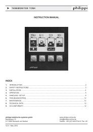
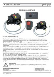
4.1 Electrical connection AC<br />
The mains connection is made by the<br />
provided mains cable with cold equipment<br />
clutch and protective contact plug. The<br />
protective contact plug may not be cut off,<br />
but it must be present a protective<br />
contact socket as interface. It is recommended,<br />
to switch the charger over an<br />
external switch in the net inlet on and off.<br />
4.2 Electrical connection DC<br />
The battery connection of the model AL<br />
12/30 takes place on the front at the plugable<br />
clamp in accordance with the diagram<br />
of connections. All other models at<br />
the clamps on the inside. To arrive the<br />
two upper screws at the front must to be<br />
removed. Afterwards the front cover can<br />
be taken off. For a professional and relia-
Operating Instructions AL<br />
ble connection the ends of the load lines must be crimped with the suitable pigtails. To ensure a suitable<br />
connection, the screws of the clamps must be tightened with a slotted bolt turner 4,5mm (AL12/30) and/or<br />
screwdrivers of size 2 (Pozidrive). If only one batterie (group) will be connected, then this is to be attached to<br />
exit +1. Further groups of batteries are attached at the exits +2 and +3.<br />
It is to be made certain absolutely that the polarity of the battery is considered. Keep the wiring between battery<br />
charger and the batteries as short as possible. Shift if possible no lines of recieving equipement parallel<br />
to the loading and main lines to avoid HF disturbances. Use as possible colored lines for battery cabling. If<br />
not possible, mark the cables with colored insulating tape. The indicated minimum cross sections of a line<br />
are to be kept absolutely.<br />
Charging current recom. fuse size Cable length 2m<br />
30 A 35 A 6 mm² 10 mm²<br />
45 A 50 A 10 mm² 16 mm²<br />
60 A 63 A 16 mm² 25 mm²<br />
The plus load lines must be secured in the proximity of the batteries by suitable fuses or breakers. The fuse<br />
size should be appropriate for something over the nominal charging current of the battery charger. Examine<br />
the wiring annually. To thin cables and/or loose connections can have dangerous overheatings at cables and<br />
installation to the consequence. Pay attention to firm connections, in order to avoid high transition resistances.<br />
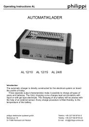
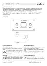
4.3 Connection of the temperature sensors<br />
The temperature sensor measures the temperature of the battery. It should be<br />
attached therefore at the exterior of the battery. It is sufficiently if this by means<br />
of tape at the exterior of the battery is fixed. The housing of the temperature<br />
sensor is electrically isolated. The electrical connection of the temperature sensors<br />
takes place at the lower row of terminals on the front side of the charger.<br />
The cable length of the temperature sensor amounts to 2.8 m, if this should not<br />
be sufficient it can be extended or shortened without limits. If no temperature<br />
sensor is attached, then the charger works with the standard voltage levels,<br />
which correspond to a temperature of 20 °C.<br />
4.4 Connection of charging control (Optional: FB-P)<br />
External charging control (option) is left justified put in at the upper row of terminals<br />
on the front side of the charger.<br />
terminal No. 1: white line (+ LED ye)<br />
terminal No. 2: brown line (+ LED gr)<br />
terminal No. 3: green line (- Minus)
Operating Instructions AL<br />
4.5 Connection of the display (option LCM)<br />
The connector of the external display LCM (option) is to put in right-justified at<br />
the upper roe of terminals on the front side of the charger:<br />
Klemme Nr. 3: screen<br />
Klemme Nr. 4: brown line<br />
Klemme Nr. 5: white line<br />
Klemme Nr. 6: green line<br />
4.6 DIP-switches<br />
The DIP switches are at the front side (AL 12/30), at all other models inside the charger at front side between<br />
the light emitting diodes and the connecting terminals of the temperature sensors.<br />
Changes in the Dip switches may be made only with switched off charger !<br />
Dip-switch OFF ON<br />
1 liquid Gel / AGM<br />
2 +2 Service +2 Start<br />
3 +3 Service +3 Start<br />
4 Power supply mode Charging mode<br />
Factory-installed all Dip switches are posed on ON.<br />
(1) Gel.- / Säure-Batterien<br />
Charging voltage Gel / AGM: 14,4V/13,8 V, bzw. 28,8V/27,6V.<br />
Charging voltage liquid: 14,3 V/13,6 V bzw. 28,6V/27,2V.<br />
please find also chapter 4 (Charging)<br />
(2) Outlet +2<br />
With starter mode charge will done with with reduced tension (-0,7V).<br />
With service mode charge will be done with full output voltage such as outlet +1.<br />
(3) Outlet +3<br />
With starter mode charge will done with with reduced tension (-0,7V).<br />
With service mode charge will be done with full output voltage such as outlet +1.<br />
(4) Lademodus<br />
ON: The charger works with the IUoU characteristic.<br />
OFF: The Charger works no longer with IUoU load characteristic separates only than power pack with an<br />
output voltage of 12,5V (25V for 24V of devices). The battery recognition is switched off.
Operating Instructions AL<br />
5. Operation<br />
Switch on:<br />
As soon as the charger is connected to the mains voltage, it goes into enterprise. By means of the IUoU<br />
characterisic with temperature compensation the charger can remain constant in enterprise, without damaging<br />
the batteries.<br />
5.1 Control lamps<br />
To monitor the charging progress and the operating condition 3 colored control lights are inserted in the front<br />
of the charger. These indicate the following operating conditions of the charger.<br />
control light Operating condition<br />
red yellow green<br />
● ● Power supply mode<br />
● The batteries are charging (IU-Phase).<br />
● The batteries are fully charged and now the tickle charge is running.<br />
❍ No battery is connected, short circuit, reversed connected or unloaded under<br />
3 V or. 6 V (24 V Unit).<br />
● ❍ The maximum charger temperature of 70 °C was exceeded. The charger<br />
limits the current, so that no further heating up takes place.<br />
● ❍ ❍ The batteries temperature run out of the range (-10 - 50 °C). The charging will<br />
be stopped until the batterie temperature will be back in the range.<br />
● ● ● A temperature sensor ist short circuited. The charging will<br />
be stopped until the short circuit is removed.<br />
● LED leuchtet ❍ LED blinkt<br />
5.2 Charging<br />
The outlet +1 is the main exit, after the charge is primarily<br />
controlled. The batteries attached to outlet +1 are<br />
always charged with a IUoU characteristic (except power<br />
supply unit mode, then only IU characteristic curve). Further<br />
groups of batteries are attached at the outlets +2<br />
and +3, which can be set individually to service -oder<br />
starter characteristic. The attached batteries are loaded<br />
with the rated current up to reaching the gassing voltage.<br />
After reaching the gassing voltage the charging voltage is<br />
kept constant on this (absorption phase). Thereby the
Operating Instructions AL<br />
charging current sinks since the charging voltage is not any longer increased.<br />
After the absorption current is sunk under 50% of the nominal value the charging voltage still 4 hours held at<br />
the gassing voltage around an optimal volume charge to reach. After this, the charging voltage is reduced<br />
down the floating voltage, in order to compensate the self discharge of the batteries. Likewise to the battery<br />
attached consumer is along-supplied by the battery charger.<br />
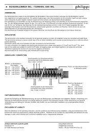
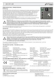
The gassing voltage of a lead-acid battery depends on the<br />
temperature. By means of a temperature sensor the battery<br />
(environment) temperature is seized and those max. charging<br />
voltage automatically adapted. Thus during the charging<br />
at different temperatures the gassings voltage of a lead-acid<br />
battery is never exceeded. If no temperature sensor is attached,<br />
with the voltage levels one loads, which correspond to<br />
a temperature of 20°C.<br />
Temperaturabhängigkeit der Gasungsspannung<br />
einer 12V-Blei-Gel-Batterie<br />
14,7<br />
14,4<br />
14,1<br />
13,8<br />
13,5<br />
13,2<br />
15<br />
-10 0 10 20 30 40 50<br />
Temperatur (°C)<br />
6. Important hints for the operation<br />
- Not used outlets have to be set to service battery use.<br />
- The battery (group) with the largest capacity/demand must be attached on outlet +1.<br />
- If only one group of batteries ist connected, then this is attached to the outlet +1.<br />
- The charger adapts to an input voltage of 120 V automatically. From the low input voltage audible noises in<br />
the switch power pack result. Around these to reduce the charging current should be halved at the load<br />
monitor LCM or the Sleep mode be activated.<br />
- Is the equipment defectively must it directly to the manufacturer be sent in, repair attempts third lead due to<br />
the complexity of the equipment not to success. Also an exchange of the safety devices is to be avoided too<br />
omitted around a further damage of the equipment.<br />
- Due to the extensive output configuration of the 3 outlets small crosswise currents between the groups of<br />
batteries during the charging will appear. These are however harmless for the battery charger and the attached<br />
batteries.<br />
- Both gel and liquid acid batteries are connected, then we recommend the charge in the gel mode.<br />
- AGM batteries must be loaded in the gel mode.<br />
Ladespannung<br />
(V)
Operating Instructions AL<br />
7. Technical datas<br />
Model AL12/30 AL 12/45 AL 12/60 AL 24/30 AL 24/60<br />
Input voltage / frequency 180-264 V *90-264 V / 50-60 Hz<br />
Full load consumption 2,3 A 3,4 A 4,5 A 4,5 A 9 A<br />
Full load consumption 530 VA 780 VA 1030 VA 1030 VA 2070 VA<br />
Rated battery voltage 12 V 24 V<br />
Output voltage @20°C Gel/AGM 14,4 V Gel/AGM 28,8 V<br />
bulk / absorption liquid 14,3 V liquid 28,6 V<br />
Output voltage @20°C Gel/AGM 13,8 V Gel/AGM 27,6 V<br />
float liquid 13,6 V liquid 27.2 V<br />
Charge current (+/- 1A)<br />
recommended<br />
30 A 45 A 60 A 30 A 60 A<br />
total batteries capacity 100- 300 Ah 150-450 Ah 200-600 Ah 100-300 Ah 200-600 Ah<br />
Characteristic IUoU<br />
Temperature range -10 °C / +40 °C, with following power reduction<br />
Cooling Temperatur controlled fan, operation from about 35°C<br />
Weight 3 kg 4 kg 4 kg 4 kg 7,8 kg<br />
Protection IP 20<br />
Dimensions BxTxH (mm) 190x275x95 260x300x95 260x300x95 260x300x95 260x300x165<br />
* With 110V -120V nominal input voltage the power will reduced to the half rated output.<br />
8 Declaration of comformity<br />
Manufacturer: philippi elektrische systeme<br />
Address: Neckaraue 19<br />
71686 Remseck - Germany<br />
Herewith declares that:<br />
the chargers are in conformity with the provision of the EC EMC directive 89/336/EEC<br />
and amendments 92/31/EEC and 93/68/EEC.<br />
V1.2 - Mai 2005