
Create successful ePaper yourself
Turn your PDF publications into a flip-book with our unique Google optimized e-Paper software.
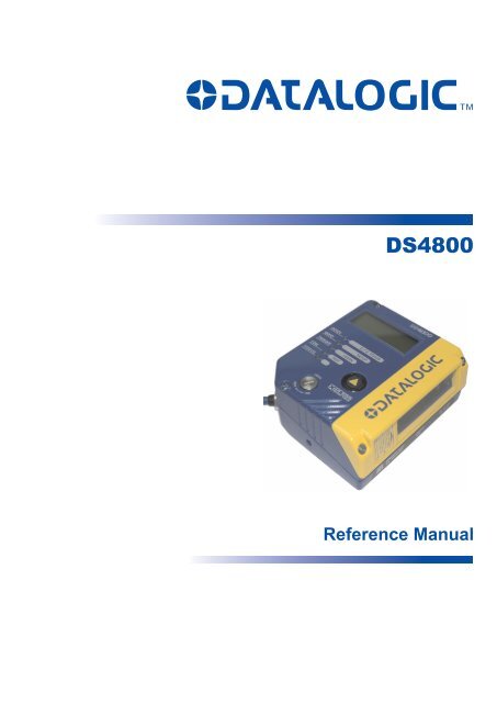
DS4800<br />
Reference Manual
Datalogic Automation Srl<br />
Via S. Vitalino, 13<br />
40012 - Lippo di Calderara di Reno<br />
Bologna - Italy<br />
DS4800 Reference Manual<br />
Ed.: 07/2009<br />
© 2008 – 2009 Datalogic Automation S.r.l. � ALL RIGHTS RESERVED. � Protected to the fullest<br />
extent under U.S. and international laws. Copying, or altering of this document is prohibited without<br />
express written consent from Datalogic Automation S.r.l.<br />
Datalogic and the Datalogic logo are registered trademarks of Datalogic S.p.A. in many countries,<br />
including the U.S.A. and the E.U.<br />
ID-NET, Genius and X-PRESS are trademarks of Datalogic Automation S.r.l. All other brand and<br />
product names mentioned herein are for identification purposes only and may be trademarks or<br />
registered trademarks of their respective owners.<br />
Datalogic shall not be liable for technical or editorial errors or omissions contained herein, nor for<br />
incidental or consequential damages resulting from the use of this material.<br />
22/07/09
CONTENTS<br />
REFERENCES .............................................................................................................v<br />
Conventions.................................................................................................................. v<br />
Reference Documentation ............................................................................................ v<br />
Services and Support ................................................................................................... v<br />
Patents.......................................................................................................................... v<br />
SAFETY AND COMPLIANCE NOTICES....................................................................vi<br />
Laser Safety................................................................................................................. vi<br />
FCC Compliance .........................................................................................................vii<br />
Power Supply...............................................................................................................vii<br />
CE Compliance............................................................................................................vii<br />
Handling......................................................................................................................viii<br />
GENERAL VIEW ..........................................................................................................x<br />
1 RAPID CONFIGURATION ...........................................................................................1<br />
Step 1 – Connect the System .......................................................................................1<br />
Step 2 – Mount and Position the Scanner ....................................................................4<br />
Step 3 – Focus the Scanner .........................................................................................5<br />
Step 4 – X-PRESS Configuration..............................................................................6<br />
Step 5 – Install Genius Configuration Program.......................................................10<br />
Step 6 – Test Mode ....................................................................................................15<br />
Advanced Scanner Configuration ...............................................................................16<br />
2 INTRODUCTION ........................................................................................................18<br />
2.1 Product Description ....................................................................................................18<br />
2.1.1 Indicators ....................................................................................................................19<br />
2.2 ID-NET ....................................................................................................................19<br />
2.2.1 How To Setup/Configure the Scanner Network..........................................................21<br />
2.3 X-PRESS Human Machine Interface ......................................................................22<br />
2.3.1 Diagnostic Indication...................................................................................................22<br />
2.3.2 X-PRESS Functions................................................................................................23<br />
2.4 Display........................................................................................................................25<br />
2.4.1 Display Messages.......................................................................................................26<br />
2.5 Oscillating Mirror Models ............................................................................................29<br />
2.6 Subzero Temperature Models ....................................................................................30<br />
2.7 Model Description .......................................................................................................31<br />
2.8 Accessories ................................................................................................................31<br />
3 INSTALLATION .........................................................................................................32<br />
3.1 Package Contents ......................................................................................................32<br />
3.2 Mechanical Installation ...............................................................................................33<br />
3.2.1 Mounting DS4800 .......................................................................................................36<br />
3.3 Positioning ..................................................................................................................39<br />
4 CBX ELECTRICAL CONNECTIONS.........................................................................41<br />
4.1 Power Supply..............................................................................................................42<br />
4.2 Main Serial Interface...................................................................................................42<br />
4.2.1 RS232 Interface..........................................................................................................43<br />
4.2.2 RS485 Full-Duplex Interface.......................................................................................44<br />
4.2.3 RS485 Half-Duplex Interface ......................................................................................45<br />
4.3 ID-NET Interface .....................................................................................................47<br />
iii
4.3.1 ID-NET Cables ........................................................................................................47<br />
4.3.2 ID-NET Response Time ..........................................................................................48<br />
4.3.3 ID-NET Network Termination ..................................................................................52<br />
4.4 Auxiliary RS232 Interface ...........................................................................................52<br />
4.5 Inputs..........................................................................................................................53<br />
4.5.1 Code Verifier...............................................................................................................56<br />
4.6 Outputs .......................................................................................................................56<br />
4.7 User Interface - Host...................................................................................................58<br />
5 25-PIN CABLE ELECTRICAL CONNECTIONS........................................................59<br />
5.1 Power Supply..............................................................................................................60<br />
5.2 Main Serial Interface...................................................................................................60<br />
5.2.1 RS232 Interface..........................................................................................................61<br />
5.2.2 RS485 Full-Duplex Interface.......................................................................................62<br />
5.2.3 RS485 Half-Duplex Interface ......................................................................................63<br />
5.3 ID-NET Interface .....................................................................................................65<br />
5.3.1 ID-NET Cables ........................................................................................................65<br />
5.3.2 ID-NET Response Time ..........................................................................................66<br />
5.3.3 ID-NET Network Termination ..................................................................................70<br />
5.4 Auxiliary RS232 Interface ...........................................................................................70<br />
5.5 Inputs..........................................................................................................................71<br />
5.5.1 Code Verifier...............................................................................................................74<br />
5.6 Outputs .......................................................................................................................74<br />
5.7 User Interface - Host...................................................................................................75<br />
6 TYPICAL LAYOUTS ..................................................................................................76<br />
6.1 Point-to-Point ..............................................................................................................76<br />
6.2 Pass-Through .............................................................................................................78<br />
6.3 ID-NET ....................................................................................................................80<br />
6.4 RS232 Master/Slave...................................................................................................83<br />
6.5 Multiplexer Layout.......................................................................................................84<br />
7 READING FEATURES...............................................................................................85<br />
7.1 Advanced Code Reconstruction (ACR 4)................................................................85<br />
7.1.1 Tilt Angle for Advanced Code Reconstruction ............................................................86<br />
7.1.2 Advanced Code Reconstruction Reading Conditions.................................................87<br />
7.2 Linear Code Reading..................................................................................................89<br />
7.2.1 Step-Ladder Mode ......................................................................................................89<br />
7.2.2 Picket-Fence Mode.....................................................................................................90<br />
7.3 Performance ...............................................................................................................91<br />
7.4 Reading Diagrams ......................................................................................................92<br />
7.4.1 X0XX Standard Models ..............................................................................................92<br />
7.4.2 X1XX Oscillating Mirror Models ..................................................................................95<br />
7.4.3 XXX5 Subzero Models................................................................................................98<br />
8 MAINTENANCE .......................................................................................................101<br />
8.1 Cleaning....................................................................................................................101<br />
9 TROUBLESHOOTING .............................................................................................102<br />
9.1 General Guidelines ...................................................................................................102<br />
10 TECHNICAL FEATURES.........................................................................................105<br />
iv<br />
GLOSSARY..............................................................................................................107<br />
INDEX.......................................................................................................................110
REFERENCES<br />
CONVENTIONS<br />
This manual uses the following conventions:<br />
“User” or “Operator” refers to anyone using a DS4800.<br />
“Device” refers to the DS4800.<br />
“You” refers to the System Administrator or Technical Support person using this manual to<br />
install, mount, operate, maintain or troubleshoot a DS4800.<br />
REFERENCE DOCUMENTATION<br />
The documentation related to the DS4800 management is listed below:<br />
� CBX100 Installation Manual<br />
� CBX500 Installation Manual<br />
� CBX Accessory Manuals<br />
� Genius Help On Line<br />
SERVICES AND SUPPORT<br />
Datalogic provides several services as well as technical support through its website. Log on<br />
to www.automation.datalogic.com and click on the links indicated for further information<br />
including:<br />
� PRODUCTS<br />
Search through the links to arrive at your product page where you can download specific<br />
Manuals and Software & Utilities including:<br />
- Genius a utility program, which allows device configuration using a PC. It provides<br />
RS232 interface configuration.<br />
� SERVICES & SUPPORT<br />
- Datalogic Services - Warranty Extensions and Maintenance Agreements<br />
- Authorised Repair Centres<br />
� CONTACT US<br />
E-mail form and listing of Datalogic Subsidiaries<br />
PATENTS<br />
This product is covered by one or more of the following patents:<br />
U.S. patents 5,992,740; 6,394,352 B1; 6,742,710 B2; 6,688,524 B1<br />
European patents 789,315 B1; 959,426 B9<br />
Additional patents pending.<br />
v
SAFETY AND COMPLIANCE NOTICES<br />
LASER SAFETY<br />
The following information is provided to comply with the rules imposed by international<br />
authorities and refers to the correct use of the DS4800 scanner.<br />
Standard Regulations<br />
This scanner utilizes a low-power laser diode. Although staring directly at the laser beam<br />
momentarily causes no known biological damage, avoid staring at the beam as one would<br />
with any very strong light source, such as the sun. Avoid that the laser beam hits the eye of<br />
an observer, even through reflective surfaces such as mirrors, etc.<br />
This product conforms to the applicable requirements of both EN 60825-1 and CDRH 21<br />
CFR 1040 at the date of manufacture. The scanner is classified as a Class 2 laser product<br />
according to EN 60825-1 regulations and as a Class II laser product according to CDRH<br />
regulations.<br />
There is a safety device, which allows the laser to be switched on only if the motor is rotating<br />
above the threshold for its correct scanning speed.<br />
The laser beam can be switched off through a software command (see also the Genius<br />
Help On Line).<br />
WARNING<br />
Use of controls or adjustments or performance of procedures other than<br />
those specified herein may result in exposure to hazardous visible laser<br />
light.<br />
The laser light is visible to the human eye and is emitted from the window on the front of the<br />
scanner (Figure A, 5).<br />
Warning labels indicating exposure to laser light and the device classification are applied<br />
onto the body of the scanner.<br />
Disconnect the power supply when opening the device<br />
during maintenance or installation to avoid exposure to<br />
hazardous laser light.<br />
The laser diode used in this device is classified as a class 3B<br />
laser product according to EN 60825-1 regulations and as a<br />
Class IIIb laser product according to CDRH regulations.<br />
Any violation of the optic parts in particular can cause<br />
radiation up to the maximum level of the laser diode (40 mW<br />
at 630 to 680 nm).<br />
vi<br />
AVOID EXPOSURE<br />
LASER LIGHT IS EMITTED<br />
FROM THIS APERTURE<br />
CAUTION-CLASS 3B<br />
LASER LIGHT WHEN OPEN<br />
AVOID EXPOSURE TO BEAM<br />
Warning and Device Class Labels<br />
This product conforms to the<br />
applicable requirements<br />
of 21CFR1040 at the date<br />
of manufacture<br />
LASER LIGHT<br />
DO NOT STARE INTO BEAM<br />
CLASS 2 LASER PRODUCT<br />
MAX. OUTPUT RADIATION 1 mW<br />
EMITTED WAVE LENGTH 630~680 nm<br />
TO EN 60825-1:1993; A1 2001<br />
U.S. pat. 5,992,740; 6,394,352B1; 6,742,710B2; 6,688,524B1.<br />
EP pat. 789,315B1; 959,426B9<br />
DATALOGIC AUTOMATION S.r.l.<br />
Via S. Vitalino, 13 – 40012 Calderara di Reno<br />
MADE IN ITALY-www.datalogic.com
FCC COMPLIANCE<br />
Modifications or changes to this equipment without the expressed written approval of<br />
Datalogic could void the authority to use the equipment.<br />
This device complies with PART 15 of the FCC Rules. Operation is subject to the following<br />
two conditions: (1) This device may not cause harmful interference, and (2) this device must<br />
accept any interference received, including interference which may cause undesired<br />
operation.<br />
This equipment has been tested and found to comply with the limits for a Class A digital<br />
device, pursuant to part 15 of the FCC Rules. These limits are designed to provide<br />
reasonable protection against harmful interference when the equipment is operated in a<br />
commercial environment. This equipment generates, uses, and can radiate radio frequency<br />
energy and, if not installed and used in accordance with the instruction manual, may cause<br />
harmful interference to radio communications. Operation of this equipment in a residential<br />
area is likely to cause harmful interference in which case the user will be required to correct<br />
the interference at his own expense.<br />
POWER SUPPLY<br />
This product is intended to be installed by Qualified Personnel only.<br />
This accessory device is intended to be supplied by a UL Listed or CSA Certified Power Unit<br />
with «Class 2» or LPS power source, which supplies power directly to the scanner via the 25pin<br />
connector.<br />
CE COMPLIANCE<br />
Warning:<br />
This is a Class A product. In a domestic environment this product may cause radio<br />
interference in which case the user may be required to take adequate measures.<br />
vii
HANDLING<br />
The DS4800 is designed to be used in an industrial environment and is built to withstand<br />
vibration and shock when correctly installed, however it is also a precision product and<br />
therefore before and during installation it must be handled correctly to avoid damage.<br />
� avoid that the scanners hit one another causing damage. They should be handled<br />
separately.<br />
� avoid that the scanners are dropped (exceeding shock limits).<br />
� do not fine tune the positioning by striking the scanner or bracket.<br />
viii
� do not weld the scanner into position which can cause electrostatic, heat or output<br />
window damage.<br />
� do not spray paint near the scanner which can cause output window damage.<br />
ix
GENERAL VIEW<br />
x<br />
1<br />
1<br />
2<br />
2<br />
3<br />
"POWER ON" LED<br />
Focus Adjustment<br />
DS4800-X0XX<br />
Figure A<br />
3 Indicator LEDs<br />
6<br />
4 Display<br />
5<br />
4<br />
6<br />
Laser Beam Output Window<br />
Push Button<br />
5
1<br />
2<br />
5<br />
"POWER ON" LED<br />
Focus Adjustment<br />
DS4800-X1XX<br />
3<br />
2<br />
4<br />
1<br />
Figure B<br />
3 Indicator LEDs<br />
6<br />
4 Display<br />
5<br />
6<br />
Laser Beam Output Window<br />
Push Button<br />
xi
xii
RAPID CONFIGURATION<br />
1 RAPID CONFIGURATION<br />
NOTE<br />
This chapter illustrates a Stand Alone application. For other types of<br />
installations, such as ID-NET, Fieldbus, Pass-Through, Multiplexer Layout,<br />
etc., refer to chapters 4, 5 and 6. For complete scanner configuration using the<br />
Genius configuration program, refer to the Context-Sensitive Help On-Line.<br />
STEP 1 – CONNECT THE SYSTEM<br />
To connect the system in a Stand Alone configuration, you need the hardware indicated in<br />
Figure 1.<br />
In this layout the data is transmitted to the Host on the main serial interface.<br />
In Local Echo communication mode, the RS232 auxiliary interface can be used to transmit<br />
data independently from the main interface selection.<br />
When On-Line Operating mode is used, the scanner is activated by an External Trigger<br />
(photoelectric sensor) when the object enters its reading zone.<br />
PG 6000<br />
MAIN<br />
DS4800 CBX100/500<br />
P.S.*<br />
I/O, AUX<br />
Figure 1 – DS4800 in Stand Alone Layout<br />
Host<br />
* Presence Sensor<br />
(for On-Line mode)<br />
1<br />
1
1<br />
CBX100/500 Pinout for DS4800<br />
DS4800 REFERENCE MANUAL<br />
The table below gives the pinout of the CBX100/500 terminal block connectors. Use this<br />
pinout when the DS4800 reader is connected by means of the CBX100/500:<br />
CBX100/500 Terminal Block Connectors<br />
Input Power Outputs<br />
Vdc Power Supply Input Voltage + +V Power Source - Outputs<br />
GND Power Supply Input Voltage - -V Power Reference - Outputs<br />
Earth Protection Earth Ground O1+ Output 1 +<br />
O1- Output 1 -<br />
Inputs O2+ Output 2 +<br />
+V Power Source – External Trigger O2- Output 2 -<br />
I1A External Trigger A (polarity insensitive) Auxiliary Interface<br />
I1B External Trigger B (polarity insensitive) TX Auxiliary Interface TX<br />
-V Power Reference – External Trigger RX Auxiliary Interface RX<br />
+V Power Source – Inputs SGND Auxiliary Interface Reference<br />
I2A Input 2 A (polarity insensitive) ID-NET<br />
I2B Input 2 B (polarity insensitive) REF Network Reference<br />
-V Power Reference – Inputs ID+ ID-NET network +<br />
Shield ID- ID-NET network -<br />
Shield Network Cable Shield<br />
Main Interface<br />
RS232 RS485 Full-Duplex RS485 Half-Duplex<br />
TX TX+ RTX+<br />
RTS TX- RTX-<br />
RX *RX+<br />
CTS *RX-<br />
SGND SGND SGND<br />
* Do not leave floating, see par. 4.2.2 for connection details.<br />
2<br />
CAUTION<br />
Do not connect GND, SGND and REF to different (external) ground<br />
references. GND, SGND and REF are internally connected through filtering<br />
circuitry which can be permanently damaged if subjected to voltage drops<br />
over 0.8 Vdc.
RAPID CONFIGURATION<br />
25-pin Connector Pinout for DS4800<br />
The table below gives the pinout of the 25-pin male D-sub connector for connection to the<br />
power supply and input/output signals. Use this pinout when the DS4800 reader is connected<br />
by means of the 25-pin connector:<br />
1<br />
14<br />
25<br />
13<br />
Figure 2 - 25-pin Male D-sub Connector<br />
25-pin D-sub male connector pinout<br />
Pin Name Function<br />
13, 9 Vdc Power supply input voltage +<br />
25, 7 GND Power supply input voltage -<br />
1 CHASSIS Cable shield connected to chassis<br />
18 I1A External Trigger A (polarity insensitive)<br />
19 I1B External Trigger B (polarity insensitive)<br />
6 I2A Input 2 A (polarity insensitive)<br />
10 I2B Input 2 B (polarity insensitive)<br />
8 O1+ Output 1 +<br />
22 O1- Output 1 -<br />
11 O2+ Output 2 +<br />
12 O2- Output 2 -<br />
20 RX Auxiliary RS232 RX<br />
21 TX Auxiliary RS232 TX<br />
23 ID+ ID-NET network +<br />
24 ID- ID-NET network -<br />
14, 15, 16, 17 NC Not Connected<br />
Pin Name RS232<br />
RS485<br />
Full-Duplex<br />
RS485<br />
Half-Duplex<br />
2 TX TX+ RTX+<br />
3 MAIN INTERFACE RX *RX+<br />
4 (SW SELECTABLE) RTS TX- RTX-<br />
5<br />
CTS *RX-<br />
* Do not leave floating, see par. 5.2.2 for connection details.<br />
1<br />
3
1<br />
STEP 2 – MOUNT AND POSITION THE SCANNER<br />
DS4800 REFERENCE MANUAL<br />
1. To mount the DS4800, use the mounting bracket to obtain the most suitable position for<br />
the reader as shown in the figures below.<br />
-45° -15° 0° 15° 45°<br />
Figure 3 - Positioning with Mounting Bracket<br />
2. When mounting the DS4800 take into consideration these three ideal label position angles:<br />
Skew 15° to 30°, Tilt 0° and Pitch 0°.<br />
S<br />
Skew<br />
Pitch<br />
Assure at least 15° Minimize Minimize<br />
Figure 4 –Skew, Tilt and Pitch Angles<br />
3. Refer to the Reading Diagrams in par. 7.4 to decide the distance your scanner should be<br />
positioned at.<br />
4<br />
T<br />
P
RAPID CONFIGURATION<br />
STEP 3 – FOCUS THE SCANNER<br />
The reading distance depends on the focus distance of the scanner and should be set<br />
according to the application requirements. The Focus Position is set directly through the<br />
focus adjustment screw on the front panel of the scanner. This screw moves the internal lens<br />
of the scanner to change the focal length of the scanner. The setting is continuous but should<br />
not be set beyond the limits "Too Far" or "Too Near" which appear on the display at the<br />
extremes of the focus range. Although the scanner reads across the entire focus range, there<br />
are three guaranteed positions which correspond to the reading diagrams in par. 7.4.<br />
1. Power up the scanner. For Subzero models, At -35 °C, a 20-minute<br />
warm-up period is required before the scanner is ready to read<br />
barcodes, the Ready LED blinks. Wait for the power up sequence<br />
to finish. By default the scanner focus is in the Unlocked<br />
position. The alternating message on the display shows the<br />
mechanical Focus Position.<br />
2. Using a screwdriver turn the focus adjustment screw in the desired<br />
direction, clockwise (focus nearer to the scanner) or<br />
counterclockwise (focus farther from the scanner). The focus<br />
position in centimeters and inches is shown on the scanner display.<br />
NOTE<br />
The value of the Focus Position must be stored in<br />
memory. If the mechanical position changes by more<br />
than the allowed tolerance of the value in memory, an<br />
alarm will be sent. See the Focus Lock function in step 4,<br />
X-PRESS Configuration.<br />
As an additional visual aid during focusing, the indicator LEDs show the relative focus<br />
position as follows:<br />
READY<br />
FOCUS<br />
GOOD<br />
SETUP<br />
TRIGGER<br />
LEARN<br />
COM<br />
TEST<br />
STATUS<br />
�<br />
less than 30 cm<br />
READY<br />
FOCUS<br />
GOOD<br />
SETUP<br />
TRIGGER<br />
LEARN<br />
COM<br />
TEST<br />
STATUS<br />
� �<br />
40 cm MEDIUM<br />
READY<br />
GOOD<br />
TRIGGER<br />
COM<br />
STATUS<br />
READY<br />
GOOD<br />
TRIGGER<br />
COM<br />
STATUS<br />
TEST<br />
LEARN<br />
� �<br />
30 cm NEAR<br />
TEST<br />
LEARN<br />
� �<br />
42-58 cm<br />
SETUP<br />
SETUP<br />
FOCUS<br />
FOCUS<br />
READY<br />
FOCUS<br />
GOOD<br />
SETUP<br />
TRIGGER<br />
LEARN<br />
COM<br />
TEST<br />
STATUS<br />
�<br />
more than 60 cm<br />
READY<br />
GOOD<br />
TRIGGER<br />
COM<br />
STATUS<br />
READY<br />
GOOD<br />
TRIGGER<br />
COM<br />
STATUS<br />
TEST<br />
LEARN<br />
� �<br />
32-38 cm<br />
TEST<br />
LEARN<br />
� �<br />
60 cm FAR<br />
SETUP<br />
SETUP<br />
1<br />
FOCUS<br />
FOCUS<br />
5
1<br />
STEP 4 – X-PRESS CONFIGURATION<br />
DS4800 REFERENCE MANUAL<br />
X-PRESS is the intuitive Human Machine Interface designed to improve ease of<br />
installation and maintenance.<br />
Status and diagnostic information are clearly presented by means of the five colored LEDs,<br />
whereas the single push button gives immediate access to the following relevant functions:<br />
� AutoSetup to self-optimize and auto-configure<br />
reading performance in demanding applications<br />
� AutoLearn to self-detect and auto-configure for<br />
reading unknown barcodes (by type and length)<br />
� Focus Lock to memorize the mechanical focus<br />
position<br />
� Test Mode with bar graph visualization to check<br />
static reading performance<br />
The colors and meaning of the five LEDs are illustrated in the following table:<br />
LED Color Description<br />
READY Green<br />
This LED indicates the device is ready to operate. For Subzero<br />
models this LED blinks during the warm-up phase.<br />
GOOD Green This LED confirms successful reading.<br />
TRIGGER Yellow This LED indicates the status of the reading phase. *<br />
COM Yellow This LED indicates active communication on main serial port. **<br />
STATUS Red This LED indicates a NO READ result.<br />
* In On-Line mode the TRIGGER LED corresponds to the active reading phase signaled by the Presence Sensor.<br />
In Automatic and Continuous modes the TRIGGER LED is always on indicating that the reader is ready to read a<br />
code.<br />
** When connected to a Fieldbus network through the CBX500, the COM LED is always active, even in the<br />
absence of data transmission, because of polling activity on the Fieldbus network.<br />
During the reader startup (reset or restart phase), all the LEDs blink for one second.<br />
On the back of the reader near the cable, the “POWER ON” LED indicates the laser scanner<br />
is correctly powered.<br />
6<br />
NOTE<br />
When entering the X-PRESS interface on the DS4800-X1XX the Oscillating<br />
Mirror remains in the default fixed position (0°) in order to make barcode<br />
reading easier while performing the X-PRESS functions.
RAPID CONFIGURATION<br />
Auto Learn<br />
If you are configuring your scanner using X-PRESS, you must start with the Auto Learn<br />
procedure.<br />
1. Enter the Auto Learn function by holding the X-PRESS push button pressed until the<br />
LEARN LED is on.<br />
2. Release the button to enter the Auto Learn function.<br />
Once entered, the reader starts a procedure to automatically detect and recognize<br />
barcodes (by type and length), which are presented to it (*). The laser turns on and the<br />
LEARN LED blinks to indicate the ongoing process.<br />
READY<br />
GOOD<br />
TRIGGER<br />
COM<br />
STATUS<br />
TEST<br />
LEARN<br />
SETUP<br />
FOCUS<br />
green<br />
green<br />
yellow<br />
yellow<br />
red<br />
Figure 5 – X-PRESS Interface: Auto Learn Function<br />
The procedure is as follows:<br />
A) place the desired barcode on<br />
the scanline.<br />
B) wait until the LEARN LED<br />
stays steady on (indicating the<br />
reader has detected the<br />
barcode).<br />
C) repeat, if needed, the above<br />
two steps to program up to 10<br />
different barcodes (the LEARN<br />
LED returns to the blinking<br />
state for the next code). If<br />
more than one barcode is<br />
detected in the scan line, the<br />
Multi Label mode is enabled<br />
(refer to the “2K/4K Family<br />
Software Configuration<br />
Parameter Guide” Help file).<br />
3. Exit the process by pressing the X-PRESS push button once. The scanner will restart<br />
at the end of the process, and then the detected barcodes are automatically configured in<br />
scanner memory.<br />
NOTE<br />
NOTE<br />
If the barcode cannot be read because of low contrast or excessive ambient<br />
light, you can perform the AutoSetup function to optimize the optical<br />
parameters. Then you can perform AutoLearn to recognize the barcode<br />
symbology.<br />
On exit from Autolearn, the following parameters are forced: Code<br />
Combination = Single Label, Reading Mode = Linear. If necessary, these<br />
parameters can be changed through Genius.<br />
* In case of Programming Barcodes (refer to the “ID-NET: Programming Barcodes And Setup Procedure”<br />
document in the product CD).<br />
1<br />
7
1<br />
Auto Setup (Optional)<br />
DS4800 REFERENCE MANUAL<br />
At the end of the Auto Learn procedure, you have the possibility to follow the Auto Setup<br />
procedure to set up the reading parameters.<br />
1. Enter the Auto Setup function by holding the X-PRESS push button pressed until the<br />
SETUP LED is on.<br />
2. Release the button to enter the Auto Setup function.<br />
3. Once entered, if a barcode label is positioned in front of the scanline, the scanner<br />
automatically performs the optimal setup of the reading parameters for that specific<br />
barcode.<br />
READY<br />
GOOD<br />
TRIGGER<br />
COM<br />
STATUS<br />
TEST<br />
LEARN<br />
SETUP<br />
FOCUS<br />
green<br />
green<br />
yellow<br />
yellow<br />
red<br />
Figure 6 – X-PRESS Interface: Auto Setup Function<br />
The procedure is as follows:<br />
A) place the desired barcode on<br />
the scanline.<br />
B) enter the AutoSetup function<br />
(the laser turns on and the<br />
SETUP LED blinks to indicate<br />
the ongoing process)<br />
C) wait until the SETUP LED<br />
stays steady on (indicating the<br />
reader has detected the<br />
barcode)<br />
This procedure ends either when the barcode is successfully decoded or after a timeout of<br />
about 7 (seven) seconds.<br />
The scanner will restart at the end of the process, and then the optimized reading<br />
parameters for that barcode are automatically configured in scanner memory.<br />
8
RAPID CONFIGURATION<br />
Focus Lock/Unlock<br />
You must perform the Focus Lock procedure to save the mechanical focus position to<br />
memory. If the mechanical focus position is changed by more than the allowed tolerance of<br />
the value in memory, a diagnostic alarm will be sent to the display.<br />
1. Enter the Focus Lock function by holding the X-PRESS push button pressed until the<br />
FOCUS LOCK LED is on.<br />
2. Release the button to enter the Focus Lock function.<br />
Once entered, the scanner automatically performs the Lock (saving) or Unlock procedure<br />
depending on the previous state of the Locked Position parameter.<br />
READY<br />
GOOD<br />
TRIGGER<br />
COM<br />
STATUS<br />
TEST<br />
LEARN<br />
SETUP<br />
FOCUS<br />
green<br />
green<br />
yellow<br />
yellow<br />
Figure 7 – X-PRESS Interface: Focus Lock/Unlock<br />
Function<br />
red<br />
The scanner will restart at the end of the process.<br />
NOTE<br />
The procedure is as follows:<br />
A) enter the Focus Lock function<br />
B) wait until the "Focus locked at..."<br />
message appears on the display<br />
(indicating the focus position has<br />
been saved to memory). The<br />
following parameters are set:<br />
� Locked Position = your mechanical<br />
setting<br />
� Focus Displacement (Alarm) = set<br />
(default to display only)<br />
If your application has been configured using X-PRESS, go to STEP 6.<br />
Reset Scanner to Factory Default (Optional)<br />
If it ever becomes necessary to reset the scanner to the factory default values, you can<br />
perform this procedure by holding the X-PRESS push button pressed while powering up<br />
the scanner. At the end of the procedure (about 5-6 seconds), the Configuration and<br />
Environmental parameters are reset, all LEDs blink simultaneously 3 times and the message<br />
"Default Set" is shown on the display.<br />
1<br />
9
1<br />
STEP 5 – INSTALL GENIUS CONFIGURATION PROGRAM<br />
DS4800 REFERENCE MANUAL<br />
Genius is a Datalogic scanner configuration tool providing several important advantages:<br />
� Wizard approach for new users;<br />
� Multi-language version;<br />
� Defined configuration directly stored in the reader;<br />
� Communication protocol independent from the physical interface allowing to consider the<br />
reader as a remote object to be configured and monitored.<br />
To install Genius, turn on the PC that will be used for the configuration, running<br />
Windows 98, 2000/NT, XP or Vista, then insert the Genius CD-ROM, wait for the CD to<br />
autorun and follow the installation procedure.<br />
This configuration procedure assumes scanner connection to a CBX100/500. Genius,<br />
running on a laptop computer, is connected to the scanner auxiliary port through the<br />
CBX100/500 9-pin connector. To communicate with the scanner, Genius performs an auto<br />
baudrate detection starting from its default parameters which are 115200, 8, N, 1. These<br />
parameters can also be set in the Genius Tools>Options>Communications window.<br />
Wizard for Quick Reader Setup<br />
After installing the Genius software program the following window appears asking the user<br />
to choose the desired configuration level.<br />
Figure 8 - Genius Wizard Opening Window<br />
The Wizard option is advised for rapid configuration or for new users, since it shows a stepby-step<br />
scanner configuration.<br />
10
RAPID CONFIGURATION<br />
1. Select the Create a new configuration button.<br />
You will be guided through the configuration being asked to define the following<br />
parameters:<br />
a. Barcode selection and definition<br />
1<br />
11
12<br />
1<br />
b. Operating mode selection and definition<br />
c. Digital Outputs configuration<br />
DS4800 REFERENCE MANUAL
RAPID CONFIGURATION<br />
d. Hardware interface selection<br />
e. Output data format configuration<br />
The On Line operating Mode requires the reader to be connected to an External<br />
Trigger/Presence Sensor using I1A and I1B inputs.<br />
The Automatic operating mode does not require connection to an external Presence<br />
Sensor. When working in this mode the reader is continuously scanning, while the<br />
reading phase is activated each time a barcode enters the reader reading zone. The<br />
reader stops reading after an N number of scans without a code. Barcode characters<br />
are transmitted on the serial interface. In case of a failed reading phase no message is<br />
sent to the host computer.<br />
1<br />
13
1<br />
DS4800 REFERENCE MANUAL<br />
2. After defining the parameter values the following window appears allowing to complete<br />
the reader configuration as follows:<br />
� Saving the configuration to disk;<br />
� Switching to Advanced mode;<br />
� Sending the configuration to the scanner.<br />
3. After sending the configuration to the<br />
scanner you have completed the<br />
configuration process.<br />
14<br />
4. By clicking Finish, the System<br />
Information window will be displayed<br />
with specific information concerning the<br />
scanner.
RAPID CONFIGURATION<br />
STEP 6 – TEST MODE<br />
NOTE<br />
When entering the X-PRESS interface on the DS4800-X1XX the Oscillating<br />
Mirror remains in the default fixed position (0°) in order to make barcode<br />
reading easier while performing the X-PRESS functions.<br />
Use a code suitable to your application to test the system. Alternatively, you can use the<br />
Datalogic Test Chart (Code 128).<br />
1. Enter the Test mode function by holding the X-PRESS push button pressed until the<br />
TEST LED is on.<br />
2. Release the button to enter the Test mode function.<br />
Once entered, the Bar-Graph on the five LEDs is activated and if the scanner starts<br />
reading barcodes the Bar-Graph shows the Good Read Rate. In case of no read<br />
condition, only the STATUS LED is on and blinks.<br />
READY<br />
GOOD<br />
TRIGGER<br />
COM<br />
STATUS<br />
TEST<br />
LEARN<br />
SETUP<br />
FOCUS<br />
green<br />
green<br />
yellow<br />
yellow<br />
red<br />
Figure 9 – X-PRESS Interface: Test Mode Function<br />
3. To exit the Test Mode, press the X-PRESS push button once.<br />
NOTE<br />
By default, the Test Mode exits automatically after two minutes.<br />
1<br />
15
1<br />
ADVANCED SCANNER CONFIGURATION<br />
DS4800 REFERENCE MANUAL<br />
For further details on advanced product configuration, refer to the complete Reference<br />
Manual on the installation CD-ROM or downloadable from the web site through this link:<br />
www.automation.datalogic.com/ds4800.<br />
The following are alternative or advanced scanner configuration methods:<br />
Host Mode Programming<br />
The scanner can also be configured from a host computer using the Host Mode<br />
programming procedure, by commands via the serial interface. See the Host Mode<br />
Programming file on the CD-ROM.<br />
Advanced Genius Configuration<br />
The ADVANCED selection available when starting the Genius program is addressed to<br />
expert users being able to complete a detailed scanner configuration. By choosing this option<br />
it is possible either to start a new scanner configuration or to open and modify an old one.<br />
The desired parameters can be defined in the following window, similar to the MS Explorer:<br />
16<br />
Figure 10 - Genius Parameter Explorer Window
RAPID CONFIGURATION<br />
Alternative Layouts<br />
� The ID-NET network is a built-in high-speed interface dedicated for high-speed<br />
scanner interconnection. ID-NET is in addition to the Main and Auxiliary serial<br />
interfaces.<br />
If you need to install an ID-NET network refer to the DS4800 Reference Manual.<br />
The scanner can also be configured by reading programming barcodes. See the ID-<br />
NET Setup Procedure Using Programming Barcodes printable from the CD-ROM.<br />
� If you need to install a Pass-Through network refer to the DS4800 Reference Manual.<br />
� If you need to install a Multiplexer network refer to the DS4800 Reference Manual.<br />
� If you need to install an RS232 Master/Slave (for backward compatibility) refer to the<br />
DS4800 Reference Manual.<br />
1<br />
17
2<br />
2 INTRODUCTION<br />
2.1 PRODUCT DESCRIPTION<br />
DS4800 REFERENCE MANUAL<br />
The DS4800 laser scanner satisfies the most advanced needs of a wide range of users. It<br />
has been developed focusing on the realistic requirements of its target market. The<br />
outstanding result is an extremely compact, cost-effective and easy to use industrial scanner.<br />
Standard Application<br />
Program<br />
Custom Application<br />
Programs<br />
A standard application program is factory-loaded onto the<br />
DS4800. This program controls barcode reading, serial port<br />
interfacing, data formatting and many other operating and control<br />
parameters.<br />
It is completely configurable from a host computer through the<br />
Genius utility program provided on CD with the scanner, or via<br />
the serial interface (Genius based Host Mode Programming).<br />
If the Standard Application Program does not meet your<br />
requirements, please contact your local Datalogic distributor.<br />
Some of the main features of DS4800 are listed below:<br />
� ACR4 (Advanced Code Reconstruction – 4 th Generation)<br />
� small dimensions and light weight<br />
� software programmable scanning speed<br />
� completely configurable via serial interface (Genius)<br />
� 3 serial communication interfaces (Main, Auxiliary, ID-NET)<br />
� supply voltage from 10 to 30 Vdc<br />
� reads all popular codes<br />
� test mode to verify the reading features and exact positioning of the scanner without the<br />
need for external tools<br />
� programmable in 4 different operating modes to suit the most various barcode reading<br />
system requirements<br />
� code verifier<br />
� low power consumption<br />
The DS4800 uses a solid-state laser diode as a light source; the light emitted has a<br />
wavelength between 630 and 680 nm. Refer to the section “Safety Precautions” at the<br />
beginning of this manual for information on laser safety.<br />
The protection class of the enclosure is IP65, the reader is therefore suitable for industrial<br />
environments where high protection against harsh external conditions is required.<br />
18
INTRODUCTION<br />
2.1.1 Indicators<br />
The five LEDs on the side of the scanner (Figure A, 3) indicate the following:<br />
LED Color Description<br />
READY Green<br />
This LED indicates the device is ready to operate. For Subzero<br />
models this LED blinks during the warm-up phase.<br />
GOOD Green This LED confirms successful reading.<br />
TRIGGER Yellow This LED indicates the status of the reading phase. *<br />
COM Yellow This LED indicates active communication on main serial port. **<br />
STATUS Red This LED indicates a NO READ result.<br />
* In On-Line mode the TRIGGER LED corresponds to the active reading phase signaled by the Presence Sensor.<br />
In Automatic and Continuous modes the TRIGGER LED is always on indicating that the reader is ready to read a<br />
code.<br />
** When connected to a Fieldbus network through the CBX500, the COM LED is always active, even in the<br />
absence of data transmission, because of polling activity on the Fieldbus network.<br />
During the reader startup (reset or restart phase), all the LEDs blink for one second.<br />
On the back of the reader near the cable, the “POWER ON” LED indicates the laser scanner<br />
is correctly powered.<br />
2.2 ID-NET<br />
The ID-NET network is a built-in high-speed interface dedicated<br />
for high-speed scanner interconnection. ID-NET is in addition to<br />
the Main and Auxiliary serial interfaces.<br />
The following network configurations are available:<br />
� ID-NET M/S Synchronized: Single station – multiple scanners<br />
CBX100<br />
CBX100<br />
CBX100<br />
ID-NET interface allows local connection<br />
of multiple scanners reading different sides<br />
of the same target. All scanners share a<br />
single presence sensor and<br />
activate/deactivate simultaneously.<br />
At the end of each reading phase a single<br />
data message is transmitted to the host.<br />
Thanks to ID-NET, data communication<br />
among scanners is highly efficient so that<br />
an immediate result will be available.<br />
2<br />
19
2<br />
� ID-NET M/S Multidata: Multiple stations – single scanner<br />
CBX100<br />
CBX100<br />
DS4800 REFERENCE MANUAL<br />
CBX100<br />
ID-NET interface allows connection of scanners reading objects placed on independent<br />
conveyors. All scanners are typically located far away from each other and they use a<br />
dedicated presence sensor.<br />
At the end of each reading phase, each scanner transmits its own data message to the host.<br />
Thanks to ID-NET, data collection among readers is accomplished at a high speed without<br />
the need of an external multiplexing device. This leads to an overall cost reduction and to a<br />
simple system wiring.<br />
20
INTRODUCTION<br />
2.2.1 How To Setup/Configure the Scanner Network<br />
A complete ID-NET scanner network can be rapidly setup, as follows:<br />
Mounting & Connection<br />
1. Mechanically mount/install all the readers (refer to par. 3.2 and 3.3).<br />
2. Wire ID-NET (refer to par. 4.3 or 5.3).<br />
3. Connect a PC equipped with Genius to the planned Master scanner.<br />
4. Power up the entire system.<br />
Configuration<br />
1. Launch Genius.<br />
2. From the Genius Device Menu select “Local Device Network Settings” and program the<br />
Role of the Master scanner (Synchronized or Multidata).<br />
This procedure requires the Network Baud Rate be the same for all Slaves and Master,<br />
(500 kbs is the default value). It can be changed after network setup using Genius<br />
through the Master scanner. See also the alternative procedure in the note below.<br />
3. At the prompt to "Send updated Network configuration to the Local Device" (Master)<br />
choose "Yes".<br />
4. Then run the NET-AUTOSET procedure from the Icon in the Devices Area. Genius<br />
sets all slave scanners according to the Master Role (Synchronized or Multidata), and<br />
assigns each a random address. If necessary, this address can be changed through the<br />
Network Wizard.<br />
5. Configure the System parameters via Genius.<br />
6. If using the CBX connection box equipped with a BM100 Backup module, perform<br />
System Backup at the Master.<br />
The scanner network is ready.<br />
NOTE<br />
NOTE<br />
If necessary, the ID-NET baudrate can be set individually on each Slave<br />
scanner to match the Master. Connect each Slave to Genius and set the<br />
Reading System Layout > Network Baudrate parameter. Then follow the<br />
procedure above.<br />
An alternative method of programming scanner address and role assignment<br />
can be accomplished by using the “Connectivity Programming Barcodes”<br />
(refer to the “ID-NET Setup Procedure Using Programming Barcodes”<br />
document on the product CD).<br />
2<br />
21
2<br />
2.3 X-PRESS HUMAN MACHINE INTERFACE<br />
X-PRESS is the intuitive Human Machine Interface<br />
designed with the precise goal of improving ease of<br />
installation and maintenance.<br />
Status and diagnostic information are clearly presented<br />
by means of five-colored LEDs, whereas the single<br />
multi-function key gives immediate access to relevant<br />
functions:<br />
� Autosetup to self-optimize reading performance<br />
in demanding applications<br />
� Autolearn to self-detect unknown barcodes<br />
� Focus Lock to memorize the mechanical focus<br />
position<br />
� Test Mode with bar-graph visualization to check<br />
static reading performance<br />
DS4800 REFERENCE MANUAL<br />
X-PRESS is the common interface adopted in all new products: “You learn one, you can<br />
use them all”.<br />
The colors and meaning of the five LEDs when in the one of the operating modes (On-Line,<br />
Automatic or Continuous) are illustrated in par 2.1.1.<br />
NOTE<br />
Except for the Focus Lock/Unlock function, the X-PRESS functions do not<br />
work if the motor or laser are turned off, see chp. 9 for details.<br />
2.3.1 Diagnostic Indication<br />
The “STATUS” and “READY” LEDs blink simultaneously to signal the presence of a failure.<br />
Diagnostic message can be enabled to provide details about specific failure conditions.<br />
These messages will be shown on the display and if enabled for transmission, also on the<br />
selected interfaces.<br />
At the same time one or more LEDs light up according to the following scheme:<br />
READY<br />
GOOD<br />
TRIGGER<br />
COM<br />
STATUS<br />
TEST<br />
LEARN<br />
SETUP<br />
FOCUS<br />
LED STATUS<br />
READY BLINK<br />
GOOD<br />
ON to indicate any Failure different than<br />
Motor or Laser failures.<br />
TRIGGER ON to indicate a Motor Failure.<br />
COM ON to indicate a Laser Failure.<br />
STATUS BLINK<br />
DS4800 also shows specific diagnostic messages on its display, see par. 2.4 for details.<br />
22
INTRODUCTION<br />
2.3.2 X-PRESS Functions<br />
Quick access to the following functions is provided by<br />
an easy procedure using the push button:<br />
1 – Press the button (the STATUS LED will give a<br />
visual feedback).<br />
2 – Hold the button until the specific function LED is<br />
on (TEST, LEARN or SETUP).<br />
3 – Release the button to enter the specific function.<br />
READY<br />
GOOD<br />
TRIGGER<br />
COM<br />
STATUS<br />
Once button is pressed, the cycle of LEDs activation is as follows:<br />
READY<br />
GOOD<br />
TRIGGER<br />
COM<br />
STATUS<br />
Release button to<br />
Exit<br />
READY<br />
GOOD<br />
TRIGGER<br />
COM<br />
STATUS<br />
Release<br />
button to<br />
enter AutoSetup<br />
TEST<br />
TEST<br />
LEARN<br />
LEARN<br />
SETUP<br />
SETUP<br />
Test<br />
Mode Function<br />
FOCUS<br />
FOCUS<br />
READY<br />
GOOD<br />
TRIGGER<br />
COM<br />
STATUS<br />
�<br />
Release button to<br />
enter Test Mode<br />
�<br />
READY<br />
GOOD<br />
TRIGGER<br />
COM<br />
STATUS<br />
TEST<br />
LEARN<br />
TEST<br />
LEARN<br />
SETUP<br />
SETUP<br />
FOCUS<br />
FOCUS<br />
READY<br />
GOOD<br />
TRIGGER<br />
COM<br />
STATUS<br />
TEST<br />
�<br />
Release button to<br />
enter AutoLearn<br />
READY<br />
GOOD<br />
TRIGGER<br />
COM<br />
STATUS<br />
LEARN<br />
�<br />
Release<br />
button to<br />
Release button to<br />
enter Focus Lock/Unlock Exit<br />
SETUP<br />
TEST<br />
LEARN<br />
TEST<br />
LEARN<br />
FOCUS<br />
SETUP<br />
SETUP<br />
2<br />
FOCUS<br />
FOCUS<br />
�<br />
� (cycle)<br />
Once<br />
entered, the Bar-Graph on the five LEDs is activated and if the scanner starts reading<br />
barcodes the Bar-Graph shows the Good Read Rate. In case of no read condition, only the<br />
STATUS LED is on and blinks.<br />
To<br />
exit the Test Mode, press the X-PRESS push button once.<br />
23
24<br />
2<br />
AutoLearn Function<br />
DS4800 REFERENCE MANUAL<br />
Once entered, the reader starts a procedure to automatically detect and recognize barcodes<br />
(by type and length), which are presented to it 1 . The laser turns on and the LEARN LED<br />
blinks to indicate the ongoing process.<br />
The procedure is as follows:<br />
- place the desired barcode on the scanline.<br />
- wait until the LEARN LED stays steady on (indicating the reader has detected the<br />
barcode).<br />
- repeat, if needed, the above two steps to program up to 10 different barcodes (the LEARN<br />
LED returns to the blinking state for the next code). If more than one barcode is detected<br />
in the scan line, the Multi Label mode is enabled (refer to the “2K/4K Family Software<br />
Configuration Parameter Guide” Help file).<br />
- exit the process by pressing the X-PRESS push button once.<br />
The scanner will restart at the end of the process, and then the detected barcodes are<br />
automatically configured in scanner memory.<br />
AutoSetup Function<br />
Once entered, if a barcode label is positioned in front of the scanline, the scanner<br />
automatically performs the optimal setup of the reading parameters for that specific barcode.<br />
The procedure is as follows:<br />
- place the desired barcode on the scanline.<br />
- enter the AutoSetup function (the laser turns on and the SETUP LED blinks to indicate<br />
the ongoing process).<br />
- wait until the SETUP LED stays steady on (indicating the reader has detected the<br />
barcode).<br />
This procedure ends either when the barcode is successfully decoded or after a timeout of<br />
about 7 (seven) seconds.<br />
The scanner will restart at the end of the process, and then the optimized reading<br />
parameters for that barcode are automatically configured in scanner memory.<br />
NOTE<br />
The AutoSetup function does not modify the programmed barcode<br />
symbologies. If needed, the AutoLearn function can be performed after<br />
Autosetup.<br />
1<br />
In case of Programming Barcodes (refer to the “ID-NET: Programming Barcodes And Setup Procedure”<br />
document in the product CD)
INTRODUCTION<br />
Focus Lock/Unlock<br />
Once entered, the scanner automatically performs the Focus Lock procedure to save the<br />
mechanical focus position to memory. If the mechanical focus position is changed by more<br />
than the allowed tolerance of the value in memory, a diagnostic alarm will be sent to the<br />
display.<br />
The procedure is as follows:<br />
- enter the Focus Lock function.<br />
- wait until the "Focus locked at..." message appears on the display (indicating the focus<br />
position has been saved to memory). The following parameters are set:<br />
� Locked Position = your mechanical setting<br />
� Focus Displacement (Alarm) = set (default to display only)<br />
If the Focus lock has already been set, this procedure can be used to Unlock the focus value.<br />
In this case control of the focus position is disabled.<br />
The scanner will restart at the end of the process.<br />
Reset Scanner to Factory Default<br />
If it ever becomes necessary to reset the scanner to the factory default values, you can<br />
perform this procedure by holding the X-PRESS push button pressed while powering up<br />
the scanner. At the end of the procedure (about 5-6 seconds), the Configuration and<br />
Environmental parameters are reset, all LEDs blink simultaneously 3 times and the message<br />
"Default Set" is shown on the display.<br />
2.4 DISPLAY<br />
The DS4800 is equipped with a 2 line by 16 character LCD display which shows various<br />
diagnostic, menu and operating mode messages according to a defined priority (0 = top<br />
priority):<br />
Priority Message Type<br />
0: File Transfer, Backup & Restore, Restore Default Parameters<br />
1: X-PRESS Menu Selection<br />
2: Focus Setup Procedure<br />
3: Diagnostic Alarms *<br />
4: Reading Results<br />
5: Welcome Message 2<br />
* Diagnostic Alarm Messages can be enabled/disabled in Genius.<br />
2 For Master devices only, Network Diagnostics can be enabled through the Network Status Monitor parameter in Genius<br />
instead of the Welcome Message.<br />
2<br />
25
2<br />
DS4800 REFERENCE MANUAL<br />
The display language for messages can be selected in Genius. The currently supported<br />
languages are:<br />
� English (default)<br />
� French<br />
� German<br />
� Italian<br />
� Japanese<br />
2.4.1 Display Messages<br />
The following examples of DS4800 Local Display messages are given to help interpret the<br />
information reported.<br />
Test Mode Results:<br />
A A A % Z Z Z Z Z Z Z Z Z Z Z<br />
F = X X X c m - Y Y . Y i n<br />
A = reading percentage from 000 to 100%.<br />
Z = code content.<br />
F = focus distance in given in centimetres and inches.<br />
Autolearn Results:<br />
X X X X X X X X X Y Y D G T<br />
A u t o l e a r n O k # Z Z<br />
X = recognized code symbology.<br />
Y = number of digits in the read code<br />
Z = number of configured slot (at the end of the procedure this number represents the total<br />
slots configured).<br />
Diagnostic Alarms:<br />
X = expected speed<br />
Y = actual speed<br />
Generic Alarms:<br />
A l e r t : M o t o r<br />
S p e e d = X X X X / Y Y Y Y<br />
A l e r t :<br />
F a i l u r e # X X X<br />
X = numeric error value (even if User Defined Messages are selected for data transmission<br />
the numeric error value is sent to the display)<br />
26
INTRODUCTION<br />
Slave Node Alarms:<br />
X = slave node number (1-31)<br />
Y = numeric error value<br />
Reading Results:<br />
A l e r t : I D - N E T<br />
N o d e # X X F a i l # Y Y Y<br />
A A A A X X X X X X X X X X X<br />
Y Y C o d e s<br />
A = reading result – Good (Good Read), Part (Partial Read), Mult (Multiple Read)<br />
X = code content<br />
Y = number of codes read<br />
G o o d X X X X X X X X X X X<br />
Y Y D G T D W W W S S S<br />
X = code content<br />
Y = number of digits in the code<br />
DGT = "digits"<br />
D = code direction – F=forward, R=reverse, U=unknown<br />
Linear Reading (only if the Quality Counters parameter is enabled)<br />
W = number of scans on the code<br />
S = Quality Counters value (max 100)<br />
Code Reconstruction<br />
W = number of scans on the code (max 255)<br />
S = number of decodes (max 255), on the digit in the code which was decoded the least<br />
number of times<br />
2<br />
27
2<br />
Welcome Message:<br />
The display alternates between message 1 and 2.<br />
Message 1<br />
X X X X X X X X X X X X R R R<br />
K K K Y Y Y Y Y Y Y Y Y N N N<br />
DS4800 REFERENCE MANUAL<br />
X = scanner model<br />
K = software – STD=Standard, SS=Special<br />
Y = software version<br />
R = Device Network Type – MUL=Multidata, SYN=Synchronized, ALN=Alone, MUX=Slave<br />
Mux32, MST=Master RS232, SLV=Slave RS232<br />
N = Device Network Setting – M00=ID-NET Network Master, Sxx= ID-NET Network<br />
Slave address, Axx= Mux32 Slave address, 232= RS232 network, Null string= Alone (no<br />
network)<br />
Message 2<br />
X = device serial number<br />
Z = focus position in cm<br />
Y = focus position in inches<br />
S N X X X X X X X X X<br />
F = Z Z Z C M - Y Y . Y I N<br />
Network Diagnostic Messages (Master only):<br />
The display alternates between message 1 and 2.<br />
Message 1<br />
Message 2<br />
1 N e t w o r k 1 5<br />
S S S S S S S S S S S S S S S S<br />
1 6 N e t w o r k 3 1<br />
S S S S S S S S S S S S S S S S<br />
S = Slave diagnostic condition:<br />
* = scanner OK<br />
- =scanner not detected at startup<br />
? =scanner detected at startup but not responding to diagnostic polling<br />
! = scanner diagnostic error<br />
28
INTRODUCTION<br />
2.5 OSCILLATING MIRROR MODELS<br />
The DS4800 OM is completely software controlled and software programmable through<br />
Genius which allows adjusting the oscillating frequency and the minimum and maximum<br />
oscillation angles of two separate reading zones.<br />
When the oscillating mirror is programmed to read barcode labels at small angles, position<br />
the reader to assure at least 15° for the Skew angle. This angle refers to the most inclined<br />
or external laser line, so that all other laser lines assure more than 15° Skew. This avoids the<br />
direct reflection of the laser light emitted by the reader.<br />
Figure 5 – Oscillating Mirror Skew Angle<br />
35°<br />
15°<br />
0°<br />
-5°<br />
code<br />
surface<br />
Otherwise, the scanner can be mounted at an angle of inclination of 15° in order to attain<br />
symmetrical deflection ranges.<br />
15°<br />
20°<br />
0°<br />
-20°<br />
code<br />
surface<br />
Figure 6 - Oscillating Mirror Reading Position<br />
In the above case, the zone where the scan line is perpendicular to the reflecting surface<br />
corresponds to a neutral zone at the center of the reading field.<br />
NOTE<br />
By limiting the raster width to the minimum necessary, the number of scans on<br />
the reading surface is increased.<br />
2<br />
29
2<br />
2.6 SUBZERO TEMPERATURE MODELS<br />
DS4800 REFERENCE MANUAL<br />
The DS4800 Subzero scanner is an industrial scanner designed to operate in industrial<br />
refrigerator/freezer cells or other stable subzero degree environments, which are below the<br />
operating range of standard industrial scanners. It is not designed to move between subzero<br />
and normal environments (rapid temperature changes).<br />
It has a patent-pending intelligent microprocessor-driven and very efficient internal heating<br />
system which constantly monitors and automatically controls internal temperature, heating<br />
only the necessary temperature-sensitive components and thereby keeping them functioning<br />
within their designed operating range even though the outside temperature is below this<br />
value. This results in very low overall power consumption. Part of this system also heats the<br />
Laser Beam Output window to eliminate ice and/or condensation build-up from negatively<br />
affecting the reading results.<br />
Upon power-up in a subzero environment, the scanner waits until these internal components<br />
are heated to within their operating temperature range. For example, power-up at -35 °C can<br />
take about 20 minutes before the scanner is ready to read barcodes. During this time the<br />
laser, motor, and display remain off and the Ready LED blinks, indicating the warm-up<br />
phase. Scanner communication is however operative and it can be configured through<br />
Genius or through Host Mode Programming during this phase.<br />
Internal Temperature (°C)<br />
0<br />
-35<br />
Cold Start<br />
Scanner Normal Operation<br />
Starting Point<br />
Warm-Up<br />
Phase<br />
Stabilized Temperature Phase<br />
0 20<br />
Time (min)<br />
It can be connected to the CBX100 LT subzero connection box which can also withstand the<br />
same subzero environment.<br />
30
INTRODUCTION<br />
2.7 MODEL DESCRIPTION<br />
The DS4800 scanner is available in versions that differ in regard to the following parameters:<br />
� Optical Model<br />
� Special Features<br />
2.8 ACCESSORIES<br />
Optical Model<br />
0 = Standard<br />
1 = Oscillating Mirror<br />
DS4800 - 1 X 0 X<br />
Special Features<br />
0 = Standard<br />
5 = Heater (Subzero Temp)<br />
The following accessories are available on request for the DS4800:<br />
Name<br />
Mirrors<br />
Description Part Number<br />
GFC-40<br />
Brackets<br />
105° Deflection Mirror<br />
(only for DS4800-1000 Standard readers)<br />
93ACC1785<br />
BK-4000 L-Shape Bracket 93ACC1837<br />
BK-4001<br />
Connection Boxes<br />
U-Shape Bracket 93ACC1838<br />
CBX100 Compact Connection Box 93A301067<br />
CBX100 LT Compact Connection Box Subzero<br />
(for DS4800 Subzero readers)<br />
93A301069<br />
CBX500 Modular Connection Box 93A301068<br />
BM100 Backup Module 93ACC1808<br />
BM150 CBX500 Display Module 93ACC1809<br />
BM200/210 Ethernet TCP/IP Module STD/IP65 93ACC1851, 93ACC1852<br />
BM300/310 Profibus Module STD/IP65 93ACC1810, 93ACC1811<br />
BM400 DeviceNet Module IP65 93ACC1814<br />
BM500/510/520 Ethernet/IP Module STD/IP65/IP54 93ACC1812, 93ACC1813,<br />
93ACC1840<br />
BM600 CANopen Module 93ACC1815<br />
BM700 Profinet Module 93ACC1816<br />
BM1100 CC-Link Module 93ACC1845<br />
BM1200/1210 Modbus TCP 93ACC1848, 93ACC1849<br />
BA100 DIN Rail Adapters 93ACC1821<br />
BA200 Bosch Adapters 93ACC1822<br />
BA900<br />
Sensors<br />
Two Cable Glands Panel 93ACC1847<br />
PH-1 Photocell Kit PNP 93ACC1791<br />
MEP-543<br />
Power Supplies<br />
Photocell Kit NPN 93ACC1728<br />
PG-6000/6001/6002 24 V Power Supply Unit EU/UK/US 93ACC1720, 93ACC1719,<br />
93ACC1718<br />
2<br />
31
3<br />
3 INSTALLATION<br />
3.1 PACKAGE CONTENTS<br />
DS4800 REFERENCE MANUAL<br />
Verify that the DS4800 reader and all the parts supplied with the equipment are present and<br />
intact when opening the packaging; the list of parts includes:<br />
� DS4800 reader with cable<br />
� DS4800 Quick Guide<br />
� Barcode Test Chart (Grade A)<br />
� Genius CD-ROM<br />
� Mounting Kit: - bracket<br />
- screws<br />
- flat washers<br />
- lock washers<br />
32<br />
Figure 11- DS4800 Package Contents
INSTALLATION<br />
3.2 MECHANICAL INSTALLATION<br />
DS4800 can be installed to operate in different positions. The four screw holes (M4 x 5) on<br />
the body of the reader are for mechanical fixture to the L-shaped mounting bracket.<br />
There are also three screw holes (M5 x 3) for fixture to the U-shaped mounting bracket<br />
(Accessory).<br />
The following diagrams give the overall dimensions of the scanner and mounting brackets<br />
and may be used for installation. Refer to par. 3.2.1 and 3.3 for correct positioning.<br />
85<br />
[3.34]<br />
M5<br />
M5<br />
34<br />
[1.34]<br />
10<br />
[0.39]<br />
101<br />
[3.98]<br />
7.5<br />
[0.30]<br />
13<br />
[0.51]<br />
42<br />
[1.65]<br />
mm<br />
[in]<br />
27.9<br />
[1.10]<br />
41.9<br />
[1.65]<br />
10<br />
[0.39]<br />
M4<br />
M4<br />
Figure 12 – DS4800 Overall Dimensions<br />
41.4<br />
[1.63]<br />
87.7<br />
[3.45]<br />
81<br />
[3.19]<br />
M5<br />
M4<br />
M4<br />
12.1<br />
[0.48]<br />
3<br />
5.2<br />
[0.21]<br />
37.8<br />
[1.49]<br />
37<br />
[1.46]<br />
33
34<br />
3<br />
74<br />
[2.91]<br />
mm<br />
[in]<br />
10<br />
[0.39]<br />
55<br />
[2.17]<br />
Ø4.2<br />
[Ø0.17] N°4<br />
30<br />
[1.18]<br />
=<br />
Ø4.2<br />
[Ø0.17] N°4<br />
4.2<br />
[0.17]<br />
70<br />
[2.76]<br />
80<br />
[3.15]<br />
30°<br />
Ø8.1<br />
[Ø0.32] N°2<br />
=<br />
120<br />
[4.72]<br />
8.1<br />
[0.32] N°6<br />
DS4800 REFERENCE MANUAL<br />
3<br />
[0.12]<br />
70<br />
[2.76]<br />
Figure 13 – L Shape Mounting Bracket Overall Dimensions<br />
64.2<br />
[2.53]<br />
100.6<br />
[3.96]<br />
103<br />
[4.06]<br />
3<br />
[0.12]<br />
=<br />
=<br />
108<br />
[4.25]<br />
76.9<br />
[3.03]<br />
70<br />
[2.76]<br />
=<br />
=<br />
71.6<br />
[2.82]<br />
56<br />
[2.20]<br />
Ø5.5<br />
[Ø0.22] N°2<br />
64.2<br />
[2.53]<br />
=<br />
=<br />
mm<br />
[in]<br />
Ø5.5<br />
[Ø0.22]<br />
45°<br />
8.1<br />
[0.32] N°2<br />
15° 15°<br />
Figure 14 – (Accessory) U Shape Mounting Bracket Overall Dimensions<br />
45°<br />
45°<br />
45°<br />
45°<br />
15°<br />
15°<br />
15° 15°<br />
9<br />
[0.35]<br />
27.5<br />
[1.08]<br />
45°
INSTALLATION<br />
48.4<br />
[1.90]<br />
42.5<br />
[1.67]<br />
5.9<br />
[0.23]<br />
7.8<br />
[0.31]<br />
123.4<br />
[4.86]<br />
101<br />
[3.98]<br />
116.6<br />
[4.59]<br />
MØ5<br />
MØ5<br />
34<br />
[1.34]<br />
10<br />
[0.39]<br />
7.5<br />
[0.30]<br />
7.8<br />
[0.31]<br />
13<br />
[0.51]<br />
42<br />
[1.65]<br />
mm<br />
[in]<br />
10<br />
[0.39]<br />
27.9<br />
[1.10]<br />
41.9<br />
[1.65]<br />
41.5<br />
[1.63]<br />
Figure 15 – DS4800 OM Overall Dimensions<br />
MØ4<br />
MØ4<br />
MØ5<br />
87.7<br />
[3.45]<br />
81<br />
[3.19]<br />
MØ4<br />
MØ4<br />
12.1<br />
[0.48]<br />
3<br />
5.2<br />
[0.21]<br />
37.8<br />
[1.49]<br />
37<br />
[1.46]<br />
35
3<br />
3.2.1 Mounting DS4800<br />
DS4800 REFERENCE MANUAL<br />
Using the DS4800 mounting bracket you can quickly and easily obtain standard mounting<br />
positions (i.e. 15° Skew angles) for the reader as shown in the following figures:<br />
36<br />
-45° -15° 0° 15° 45°<br />
Skew<br />
Figure 16 – Positioning with L Shape Mounting Bracket<br />
Pitch
INSTALLATION<br />
alignment marks<br />
-45°<br />
-15°<br />
0°<br />
15° 45°<br />
Skew<br />
Pitch<br />
Figure 17 – Positioning with U Shape Mounting Bracket (Accessory)<br />
3<br />
37
38<br />
3<br />
alignment marks<br />
-45°<br />
-15°<br />
0°<br />
DS4800 REFERENCE MANUAL<br />
15° 45°<br />
Skew<br />
Figure 18 – DS4800 OM Positioning with U Shape Mounting Bracket<br />
Tilt
INSTALLATION<br />
3.3 POSITIONING<br />
The DS4800 scanner is able to decode moving barcode labels at a variety of angles,<br />
however significant angular distortion may degrade reading performance.<br />
When mounting the DS4800 take into consideration these three ideal label position angles:<br />
Skew 15° to 30°, Tilt 0° and Pitch 0°.<br />
Follow the suggestions for the best orientation:<br />
The Skew angle is represented by the value S in Figure 19. Position the reader to assure at<br />
least 15° for the Skew angle. This avoids the direct reflection of the laser light emitted by the<br />
DS4800.<br />
S S<br />
Figure 19 – DS4800 Skew Angle<br />
The Tilt angle is represented by the value T in Figure 20. Position the reader in order to<br />
minimize the Tilt angle.<br />
T T<br />
Figure 20 – DS4800Tilt Angle<br />
By using the ACR4 (Advanced Code Reconstruction) software parameter, the tilt angle is<br />
less critical and can be decoded even if the scan line doesn’t cross the entire code.<br />
See par. 7.1 or the Help On Line for details.<br />
3<br />
39
40<br />
3<br />
DS4800 REFERENCE MANUAL<br />
The Pitch angle is represented by the value P in Figure 21. Position the reader in order to<br />
minimize the Pitch angle.<br />
P P<br />
Figure 21 – DS4800 Pitch Angle
CBX ELECTRICAL CONNECTIONS<br />
4 CBX ELECTRICAL CONNECTIONS<br />
All DS4800 models are equipped with a cable terminated by a 25-pin male D-sub connector<br />
for connection to the power supply and input/output signals.<br />
We recommend making system connections through one of the CBX connection boxes since<br />
they offer the advantages of easy connection, easy device replacement and filtered<br />
reference signals.<br />
NOTE<br />
If you require direct wiring to the scanner the details of the connector pins<br />
and relative connections are indicated in Chaper 5.<br />
The table below gives the pinout of the CBX100/500 terminal block connectors. Use this<br />
pinout when the DS4800 reader is connected by means of the CBX100/500:<br />
CBX100/500 Terminal Block Connectors<br />
Input Power<br />
Vdc Power Supply Input Voltage +<br />
GND Power Supply Input Voltage -<br />
Earth Protection Earth Ground<br />
Inputs<br />
+V Power Source – External Trigger<br />
I1A External Trigger A (polarity insensitive)<br />
I1B External Trigger B (polarity insensitive)<br />
-V Power Reference – External Trigger<br />
+V Power Source – Inputs<br />
I2A Input 2 A (polarity insensitive)<br />
I2B Input 2 B (polarity insensitive)<br />
-V Power Reference – Inputs<br />
Outputs<br />
+V Power Source - Outputs<br />
-V Power Reference - Outputs<br />
O1+ Output 1 +<br />
O1- Output 1 -<br />
O2+ Output 2 +<br />
O2- Output 2 -<br />
Auxiliary Interface<br />
TX Auxiliary Interface TX<br />
RX Auxiliary Interface RX<br />
SGND Auxiliary Interface Reference<br />
ID-NET<br />
REF Network Reference<br />
ID+ ID-NET network +<br />
ID- ID-NET network -<br />
Shield Network Cable Shield<br />
Main Interface<br />
RS232<br />
RS485<br />
Full-Duplex<br />
RS485<br />
Half-Duplex<br />
TX TX+ RTX+<br />
RX *RX+<br />
RTS TX- RTX-<br />
CTS *RX-<br />
SGND SGND SGND<br />
* Do not leave floating, see par. 4.2.2 for connection details.<br />
4<br />
41
4<br />
NOTE<br />
DS4800 REFERENCE MANUAL<br />
To avoid electromagnetic interference when the scanner is connected to a<br />
CBX connection box, verify the jumper positions in the CBX as indicated in<br />
its Installation Manual.<br />
4.1 POWER SUPPLY<br />
Power can be supplied to the scanner through the CBX100/500 spring clamp terminal pins<br />
as shown in Figure 22:<br />
Power Supply<br />
V+<br />
in<br />
VGND<br />
Earth<br />
Ground<br />
Figure 22 - Power Supply Connections<br />
The power must be between 10 and 30 Vdc only.<br />
It is recommended to connect the device CHASSIS to earth ground (Earth) by setting the<br />
appropriate jumper in the CBX connection box. See the CBX Installation Manual for details.<br />
4.2 MAIN SERIAL INTERFACE<br />
CAUTION<br />
Do not connect to the Main Interface spring clamp terminals if using Host<br />
Interface Modules (Fieldbus) with the CBX500.<br />
The signals relative to the following serial interface types are available on the CBX spring<br />
clamp terminal blocks.<br />
If the interface type is not compatible with the current communication handshaking, then the<br />
system forces the handshake to none.<br />
The main interface type and the relative parameters (baud rate, data bits, etc.) can be<br />
set using the Genius utility program or the Genius based Host Mode Programming<br />
procedure.<br />
Details regarding the connections and use of the interfaces are given in the next paragraphs.<br />
42
CBX ELECTRICAL CONNECTIONS<br />
4.2.1 RS232 Interface<br />
The serial interface is used in this case for point-to-point connections; it handles<br />
communication with the host computer and allows both transmission of code data and the<br />
programming of the scanner. This is the default setting.<br />
The following pins are used for RS232 interface connection:<br />
CBX100/500 Function<br />
TX Transmit Data<br />
RX Receive Data<br />
RTS Request To Send<br />
CTS Clear To Send<br />
SGND Signal Ground<br />
It is always advisable to use shielded cables. The overall maximum cable length must be<br />
less than 15 m (49.2 ft).<br />
SCANNER<br />
USER INTERFACE<br />
SGND RXD TXD<br />
CTS RTS<br />
SGND TX RX<br />
RTS CTS<br />
Figure 23 – RS232 Main Interface Connections Using Hardware Handshaking<br />
The RTS and CTS signals control data transmission and synchronize the connected devices.<br />
+ V<br />
RTS<br />
- V<br />
+ V<br />
TX DATA<br />
- V<br />
+ V<br />
CTS<br />
- V<br />
START<br />
OF<br />
TRANSMISSION<br />
DATA<br />
TRANSMISSION<br />
DATA<br />
TRANSMISSION<br />
C1 C2 C3 C4 C5<br />
ENABLED<br />
TRANSMISSION<br />
STOPPED<br />
ENABLED<br />
END<br />
OF<br />
TRANSMISSION<br />
IDLE DISABLED<br />
IDLE<br />
Figure 24 - RS232 Control Signals<br />
If the RTS/CTS handshaking protocol is enabled, the DS4800 activates the RTS output to<br />
indicate a message is to be transmitted. The receiving unit activates the CTS input to enable<br />
the transmission.<br />
4<br />
43
4<br />
4.2.2 RS485 Full-Duplex Interface<br />
DS4800 REFERENCE MANUAL<br />
The RS485 full-duplex (5 wires + shield) interface is used for non-polled communication<br />
protocols in point-to-point connections over longer distances (max 1200 m / 3940 ft) than<br />
those acceptable for RS232 communications or in electrically noisy environments.<br />
The CBX pinout follows:<br />
44<br />
NOTE<br />
CBX100/500 Function<br />
TX+ RS485 Transmit Data +<br />
RX+ RS485 Receive Data +<br />
TX- RS485 Transmit Data -<br />
RX- RS485 Receive Data -<br />
SGND Signal Ground<br />
SCANNER<br />
USER INTERFACE<br />
RX485+ TX485+<br />
SGND RX485- TX485-<br />
SGND TX+ RX+<br />
TX- RX-<br />
Figure 25 - RS485 Full-duplex Connections<br />
For applications that do not use RX485 signals, do not leave these lines<br />
floating but connect them to SGND as shown below.<br />
SCANNER<br />
USER INTERFACE<br />
RX485+<br />
SGND RX485-<br />
SGND TX+<br />
TX-<br />
Figure 26 - RS485 Full-duplex Connections using Only TX Signals
CBX ELECTRICAL CONNECTIONS<br />
4.2.3 RS485 Half-Duplex Interface<br />
NOTE<br />
This interface is provided for backward compatibility. We recommend using<br />
the more efficient ID-NET network for Master/Slave or Multiplexer layouts.<br />
The RS485 half-duplex (3 wires + shield) interface is used for polled communication<br />
protocols.<br />
It can be used for Multidrop connections with a Datalogic Multiplexer, (see par. 6.5) exploiting<br />
a proprietary protocol based on polled mode called MUX32 protocol, where a master device<br />
polls slave devices to collect data.<br />
CBX100/500 Function<br />
RTX+ RS485 Receive/Transmit Data +<br />
RTX- RS485 Receive/Transmit Data -<br />
SGND Signal Ground<br />
SCANNER<br />
USER INTERFACE<br />
RTX485+<br />
SGND RTX485-<br />
SGND RTX+<br />
RTX-<br />
Figure 27 - RS485 Half-duplex Connections<br />
This interface is forced by software when the protocol selected is MUX32 protocol.<br />
In a Multiplexer layout, the Multidrop address must also be set via serial channel by the<br />
Genius utility or by the Host Programming Mode.<br />
Error! Not a valid bookmark self-reference. shows a multidrop configuration with DS4800<br />
scanners connected to a Multiplexer.<br />
CAUTION<br />
This is an example of multidrop wiring. Consult the multiplexer manual for<br />
complete wiring instructions.<br />
4<br />
45
4<br />
Figure 28 – DS4800 Multidrop Connection to a Multiplexer<br />
*<br />
*<br />
DS4800 REFERENCE MANUAL<br />
* When using CBX500, the Main interface multidrop network signals: Shield, SGND, RTX+and RTX- are<br />
repeated on terminal connector row 4 to facilitate system cabling.<br />
46
CBX ELECTRICAL CONNECTIONS<br />
4.3 ID-NET INTERFACE<br />
CBX100/500 Function<br />
Shield Network Cable Shield<br />
ID+ ID-NET network +<br />
ID- ID-NET network -<br />
REF Network Reference<br />
4.3.1 ID-NET Cables<br />
The following instructions are referred to Figure 30, Figure 31 and Figure 32.<br />
� The general cable type specifications are: CAT5 twisted pair + additional CAT5 twisted<br />
pair, shielded cable AWG 24 (or AWG 22) stranded flexible.<br />
We recommend using DeviceNet cables (drop or trunk type) to the following reference<br />
standards:<br />
AN50325 – IEC 62026<br />
UL STYLE 2502 80°C 30V<br />
� Cable Shield MUST be connected to earth ground ONLY at the Master.<br />
� NEVER use ID-NET cable shield as common reference.<br />
� The ID-NET max cable length depends on the baudrate used, (see the Baudrate Table<br />
below).<br />
� For Common Power Connections use only 2 wires (ID+ and ID-).<br />
- DC Voltage Power cable (Vdc – GND) should be handled as a signal cable (i.e. do not<br />
put it together with AC cable):<br />
- Wire dimensioning must be checked in order to avoid voltage drops greater than 0.8<br />
Volts.<br />
- Cable should lie down as near as possible to the ID-NET cable (avoiding wide loops<br />
between them).<br />
� Scanner's chassis may be connected to earth.<br />
� Network inside the same building.<br />
Baudrate Table<br />
Baud Rate 125 kbps 250 kbps 500 kbps 1Mbps<br />
Cable Length 1200 m 900 m 700 m *<br />
* Application dependent, contact your Datalogic Automation representative for details.<br />
NOTE<br />
The default ID-NET baudrate is 500 kbps. Lower ID-NET baudrates<br />
allow longer cable lengths. The baudrate is software configurable by<br />
authorized Datalogic Automation personnel only.<br />
4<br />
47
4<br />
4.3.2 ID-NET Response Time<br />
DS4800 REFERENCE MANUAL<br />
The following figure shows the response time of the ID-NET network. This time is defined<br />
as the period between the Trigger activation and the beginning of data transmission to the<br />
Host.<br />
Response Time (ms)<br />
CONDITIONS:<br />
48<br />
240<br />
220<br />
200<br />
180<br />
160<br />
140<br />
120<br />
100<br />
80<br />
60<br />
40<br />
20<br />
0<br />
Max ID-NET Response Time<br />
0 1 2 3 4 5 6 7 8 9 10 11 12 13 14 15 16<br />
� ID-NET M/S Synchronized layout<br />
� message length = 50 bytes per node<br />
Number of Nodes<br />
500 kbps 250 kbps 125 kbps<br />
Figure 29 – ID-NET Response Time
CBX ELECTRICAL CONNECTIONS<br />
Figure 30 – ID-NET Network Connections with isolated power blocks<br />
4<br />
49
50<br />
4<br />
DS4800 REFERENCE MANUAL<br />
Figure 31 - ID-NET Network Connections with Common Power Branch Network
CBX ELECTRICAL CONNECTIONS<br />
Figure 32 – ID-NET Network Connections with Common Power Star Network<br />
4<br />
51
4<br />
4.3.3 ID-NET Network Termination<br />
DS4800 REFERENCE MANUAL<br />
The network must be properly terminated in the first and last scanner of the network. This is<br />
done by setting the ID-NET Termination Resistance Switch in the CBX100/500 to ON.<br />
4.4 AUXILIARY RS232 INTERFACE<br />
The auxiliary serial interface is used exclusively for RS232 point-to-point connections.<br />
The parameters relative to the aux interface (baud rate, data bits, etc.) as well as particular<br />
communication modes such as LOCAL ECHO can be defined using the Genius utility<br />
program or Genius based Host Mode Programming installed from the CD-ROM.<br />
The 9-pin female Auxiliary Interface connector inside the CBX is the preferred connector for<br />
device configuration or communication monitoring.<br />
5 1<br />
9<br />
Figure 33 - 9-pin female connector<br />
If permanent system wiring is required, the following pins are used to connect the RS232<br />
auxiliary interface:<br />
52<br />
NOTE<br />
CBX100/500 Function<br />
RX Auxiliary Interface Receive Data<br />
TX Auxiliary Interface Transmit Data<br />
SGND Auxiliary Interface Reference<br />
6<br />
USER INTERFACE<br />
RX TX<br />
Reference<br />
Figure 34 - RS232 Auxiliary Interface Connections<br />
Do not connect the Aux Interface to the CBX spring clamp connectors and<br />
the 9-pin connector simultaneously.
CBX ELECTRICAL CONNECTIONS<br />
4.5 INPUTS<br />
There are two optocoupled polarity insensitive inputs available on the scanner: Input 1<br />
(External Trigger) and Input 2, a generic input:<br />
The electrical features of both inputs are:<br />
Maximum voltage: 30 Vdc<br />
Maximum current: 12 mA (scanner) + 12 mA (CBX)<br />
An anti-disturbance filter is implemented in software on both inputs so that the minimum<br />
pulse duration is � 5 milliseconds. This value can be increased through the software<br />
parameter Debounce Filter, see the "2K/4K Family Software Configuration Parameter Guide”<br />
Help file".<br />
CBX100/500 Function<br />
+V Power Source - External Trigger<br />
I1A External Trigger A (polarity insensitive)<br />
I1B External Trigger B (polarity insensitive)<br />
-V Power Reference - External Trigger<br />
The External Trigger input is used in the On-Line operating Mode and tells the scanner to<br />
scan for a code. The active state of this input is selected in software. Refer to the Genius<br />
Help On Line.<br />
The yellow Trigger LED (Figure A, 3) is on when the active state of the External Trigger<br />
corresponds to ON.<br />
This input is optocoupled and can be driven by both an NPN and PNP type command. The<br />
connections are indicated in the following diagrams:<br />
EXTERNAL TRIGGER INPUT CONNECTIONS USING DS4800 POWER<br />
PH-1 Photocell (PNP)<br />
(brown)<br />
(black) (blue)<br />
Figure 35 – PH-1 Photocell (PNP) External Trigger Using DS4800 Power<br />
4<br />
53
54<br />
4<br />
NPN Photocell<br />
Power to Input<br />
Photocell Signal<br />
Photocell<br />
Reference<br />
Figure 36 - NPN External Trigger Using DS4800 Power<br />
DS4800 REFERENCE MANUAL<br />
EXTERNAL TRIGGER INPUT CONNECTIONS USING EXTERNAL POWER<br />
PNP Photocell<br />
Input<br />
Signal<br />
Pulled down to External<br />
Input Device Reference<br />
Figure 37 - PNP External Trigger Using External Power<br />
NPN Photocell<br />
Pulled up to External<br />
Input Device Power<br />
Input<br />
Signal<br />
Figure 38 - NPN External Trigger Using External Power
CBX ELECTRICAL CONNECTIONS<br />
CBX100/500 Function<br />
+V Power Source - Inputs<br />
I2A Input 2 A (polarity insensitive)<br />
I2B Input 2 B (polarity insensitive)<br />
-V Power Reference - Inputs<br />
INPUT 2 CONNECTIONS USING DS4800 POWER<br />
Input Device<br />
Power to<br />
Input Device<br />
Input Input Device<br />
Signal Reference<br />
PNP Input 2 Using DS4800 Power<br />
Input Device<br />
Power to Input<br />
Input Device Signal<br />
Input Device<br />
Reference<br />
NPN Input 2 Using DS4800 Power<br />
INPUT 2 CONNECTIONS USING EXTERNAL POWER<br />
Input Device<br />
Input<br />
Signal<br />
Pulled down to External<br />
Input Device Reference<br />
Figure 39 - PNP Input 2 Using External Power<br />
4<br />
55
4<br />
4.5.1 Code Verifier<br />
Input Device<br />
Pulled up to External<br />
Input Device Power<br />
Input<br />
Signal<br />
Figure 40 - NPN Input 2 Using External Power<br />
DS4800 REFERENCE MANUAL<br />
If the DS4800 is used as a Code Verifier, the verifier code can be configured in software<br />
through the Genius configuration program. However it is also possible to use one of the<br />
inputs to trigger when the scanner should store a code read as the verifier code.<br />
The Code Verifier parameter must be enabled, and the configuration parameters to allow<br />
correct Code Type reading must be saved to the scanner in order to read the verifier code.<br />
When the selected input is activated, the next read code will be stored as the verifier code in<br />
the scanner's non-volatile (Flash) memory.<br />
For more details see the Verifier Parameters in the "2K/4K Family Software Configuration<br />
Parameter Guide” Help file".<br />
4.6 OUTPUTS<br />
Two general purpose outputs are available.<br />
CBX100/500 Function<br />
+V Power Source - Outputs<br />
O1+ Output 1 +<br />
O1- Output 1 -<br />
O2+ Output 2 +<br />
O2- Output 2 -<br />
-V Power Reference Outputs<br />
The meaning of the two outputs Output 1 and Output 2 can be defined by the user (No Read,<br />
Right, Wrong, etc.). Refer to the Genius Help On Line.<br />
By default, Output 1 is associated with the No Read event, which activates when the code<br />
signaled by the external trigger is not decoded, and Output 2 is associated with the Complete<br />
Read event, which activates when all the selected codes are correctly decoded.<br />
The output signals are fully programmable being determined by the configured<br />
Activation/Deactivation events, Deactivation Timeout or a combination of the two.<br />
56
CBX ELECTRICAL CONNECTIONS<br />
VCE max = 30 Vdc<br />
OUTPUT CONNECTIONS USING DS4800 POWER<br />
Output Device<br />
Power to Output<br />
Output device Signal<br />
Output device<br />
Reference<br />
Figure 41 - Open Emitter Output Using DS4800 Power<br />
Output Device<br />
Power to<br />
Output device<br />
Output device<br />
Reference<br />
Output<br />
Signal<br />
Figure 42 - Open Collector Output Using DS4800 Power<br />
OUTPUT CONNECTIONS USING EXTERNAL POWER<br />
Output Device<br />
Pulled up to External<br />
Output Device Power<br />
Output<br />
Signal<br />
Figure 43 - Open Emitter Output Using External Power<br />
Output Device<br />
Output<br />
Signal<br />
Pulled down to External<br />
Output Device Reference<br />
I max = 40 mA continuous; 130 mA pulsed<br />
Figure 44 - Open Collector Output Using External Power<br />
4<br />
57
58<br />
4<br />
4.7 USER INTERFACE - HOST<br />
DS4800 REFERENCE MANUAL<br />
The following table contains the pinout for standard RS232 PC Host interface. For other user<br />
interface types please refer to their own manual.<br />
1 5<br />
6<br />
9-pin male connector<br />
RS232 PC-side connections<br />
9<br />
25-pin male connector<br />
Pin Name Pin Name<br />
2 RX 3 RX<br />
3 TX 2 TX<br />
5 GND 7 GND<br />
7 RTS 4 RTS<br />
8 CTS 5 CTS<br />
1<br />
14<br />
25<br />
13
25-PIN CABLE ELECTRICAL CONNECTIONS<br />
5 25-PIN CABLE ELECTRICAL CONNECTIONS<br />
All DS4800 models are equipped with a cable terminated by a 25-pin male D-sub connector<br />
for connection to the power supply and input/output signals. The details of the connector pins<br />
are indicated in the following table.<br />
1<br />
14<br />
25<br />
13<br />
Figure 45 - 25-pin Male D-sub Connector<br />
25-pin D-sub male connector pinout<br />
Pin Name Function<br />
13, 9 Vdc Power supply input voltage +<br />
25, 7 GND Power supply input voltage -<br />
1 CHASSIS Cable shield connected to chassis<br />
18 I1A External Trigger A (polarity insensitive)<br />
19 I1B External Trigger B (polarity insensitive)<br />
6 I2A Input 2 A (polarity insensitive)<br />
10 I2B Input 2 B (polarity insensitive)<br />
8 O1+ Output 1 +<br />
22 O1- Output 1 -<br />
11 O2+ Output 2 +<br />
12 O2- Output 2 -<br />
20 RX Auxiliary Interface RX<br />
21 TX Auxiliary Interface TX<br />
23 ID+ ID-NET network +<br />
24 ID- ID-NET network -<br />
14, 15, 16, 17 NC Not Connected<br />
Pin Name RS232<br />
RS485<br />
Full-Duplex<br />
RS485<br />
Half-Duplex<br />
2 TX TX+ RTX+<br />
3 MAIN INTERFACE RX *RX+<br />
4 (SW SELECTABLE) RTS TX- RTX-<br />
5<br />
CTS *RX-<br />
* Do not leave floating, see par. 5.2.2 for connection details.<br />
5<br />
59
5<br />
5.1 POWER SUPPLY<br />
DS4800 REFERENCE MANUAL<br />
Power can be supplied to the scanner through the pins provided on the 25-pin connector<br />
used for communication with the host (Figure 46):<br />
DS4800<br />
13<br />
25<br />
1<br />
Vdc<br />
GND<br />
CHASSIS<br />
Earth Ground<br />
POWER SUPPLY<br />
V+ (10 - 30 Vdc)<br />
VGND<br />
CHASSIS<br />
Figure 46 - Power Supply Connections<br />
The power must be between 10 and 30 Vdc only.<br />
It is recommended to connect pin 1 (CHASSIS) to a common earth ground.<br />
5.2 MAIN SERIAL INTERFACE<br />
The signals relative to the following serial interface types are available on the input/output<br />
connector of DS4800.<br />
If the interface type is not compatible with the current communication handshaking, then the<br />
system forces the handshake to none.<br />
The main interface type and the relative parameters (baud rate, data bits, etc.) can be<br />
set using the Genius utility program or the Genius based Host Mode Programming<br />
procedure.<br />
Details regarding the connections and use of the interfaces are given in the next paragraphs.<br />
60
25-PIN CABLE ELECTRICAL CONNECTIONS<br />
5.2.1 RS232 Interface<br />
The serial interface is used in this case for point-to-point connections; it handles<br />
communication with the host computer and allows both transmission of code data and the<br />
programming of the scanner. This is the default setting.<br />
The following pins are used for RS232 interface connection:<br />
25-pin Name Function<br />
2 TX Transmit Data<br />
3 RX Receive Data<br />
4 RTS Request To Send<br />
5 CTS Clear To Send<br />
7 GND Ground<br />
It is always advisable to use shielded cables. The overall maximum cable length must be<br />
less than 15 m (49.2 ft).<br />
DS4800<br />
Chassis<br />
2<br />
3<br />
4<br />
5<br />
7<br />
1<br />
TX<br />
RX<br />
RTS<br />
CTS<br />
GND<br />
USER INTERFACE<br />
RXD<br />
TXD<br />
CTS<br />
RTS<br />
GND<br />
Figure 47 – RS232 Main Interface Connections Using Hardware Handshaking<br />
The RTS and CTS signals control data transmission and synchronize the connected devices.<br />
+ V<br />
RTS<br />
- V<br />
+ V<br />
TX DATA<br />
- V<br />
+ V<br />
CTS<br />
- V<br />
START<br />
OF<br />
TRANSMISSION<br />
DATA<br />
TRANSMISSION<br />
DATA<br />
TRANSMISSION<br />
C1 C2 C3 C4 C5<br />
ENABLED<br />
TRANSMISSION<br />
STOPPED<br />
ENABLED<br />
END<br />
OF<br />
TRANSMISSION<br />
IDLE DISABLED<br />
IDLE<br />
Figure 48 - RS232 Control Signals<br />
If the RTS/CTS handshaking protocol is enabled, the DS4800 activates the RTS output to<br />
indicate a message is to be transmitted. The receiving unit activates the CTS input to enable<br />
the transmission.<br />
5<br />
61
5<br />
5.2.2 RS485 Full-Duplex Interface<br />
DS4800 REFERENCE MANUAL<br />
The RS485 full-duplex (5 wires + shield) interface is used for non-polled communication<br />
protocols in point-to-point connections over longer distances (max 1200 m / 3940 ft) than<br />
those acceptable for RS232 communications or in electrically noisy environments.<br />
The connector pinout follows:<br />
62<br />
25-pin Name Function<br />
2 TX+ RS485 Transmit Data +<br />
3 RX+ RS485 Receive Data +<br />
4 TX- RS485 Transmit Data -<br />
5 RX- RS485 Receive Data -<br />
7 GND Ground<br />
NOTE<br />
Chassis<br />
DS4800<br />
2<br />
4<br />
3<br />
5<br />
TX+<br />
TX-<br />
RX+<br />
RX-<br />
7 GND<br />
1<br />
USER INTERFACE<br />
+<br />
-<br />
+<br />
-<br />
RX485<br />
TX485<br />
GND<br />
Figure 49 - RS485 Full-duplex Connections<br />
For applications that do not use RX signals, do not leave these lines floating<br />
but connect them to GND as shown below.<br />
Chassis<br />
DS4800<br />
2<br />
4<br />
3<br />
5<br />
TX+<br />
TX-<br />
RX+<br />
RX-<br />
7 GND<br />
1<br />
USER INTERFACE<br />
+<br />
-<br />
RX485<br />
GND<br />
Figure 50 - RS485 Full-duplex Connections using Only TX Signals
25-PIN CABLE ELECTRICAL CONNECTIONS<br />
5.2.3 RS485 Half-Duplex Interface<br />
NOTE<br />
This interface is provided for backward compatibility. We recommend using<br />
the more efficient ID-NET network for Master/Slave or Multiplexer layouts.<br />
The RS485 half-duplex (3 wires + shield) interface is used for polled communication<br />
protocols.<br />
It can be used for Multidrop connections with a Datalogic Multiplexer, (see par. 6.5) exploiting<br />
a proprietary protocol based on polled mode called MUX32 protocol, where a master device<br />
polls slave devices to collect data.<br />
The connector pinout follows:<br />
25-pin Name Function<br />
2 RTX+ RS485 Receive/Transmit Data +<br />
4 RTX- RS485 Receive/Transmit Data -<br />
7 GND Ground<br />
DS4800<br />
Chassis<br />
2<br />
4<br />
RTX+<br />
RTX-<br />
7 GND<br />
1<br />
MULTIPLEXER<br />
RTX485 +<br />
RTX485 -<br />
RS485REF<br />
Figure 51 - RS485 Half-duplex Connections<br />
This interface is forced by software when the protocol selected is MUX32 protocol.<br />
In a Multiplexer layout, the Multidrop address must also be set via serial channel by the<br />
Genius utility or by the Host Programming Mode.<br />
Figure 52 shows a multidrop configuration with DS4800 scanners connected to a Multiplexer.<br />
CAUTION<br />
This is an example of multidrop wiring. Consult the multiplexer manual for<br />
complete wiring instructions.<br />
5<br />
63
64<br />
5<br />
Figure 52 - DS4800 Multidrop Connection to a Multiplexer<br />
DS4800 REFERENCE MANUAL
25-PIN CABLE ELECTRICAL CONNECTIONS<br />
5.3 ID-NET INTERFACE<br />
25-pin Name Function<br />
23 ID+ ID-NET network +<br />
24 ID- ID-NET network -<br />
7 GND Ground<br />
5.3.1 ID-NET Cables<br />
The following instructions are referred to Figure 54, Figure 55 and Figure 56.<br />
� The general cable type specifications are: CAT5 twisted pair + additional CAT5 twisted<br />
pair, shielded cable AWG 24 (or AWG 22) stranded flexible.<br />
We recommend using DeviceNet cables (drop or trunk type) to the following reference<br />
standards:<br />
AN50325 – IEC 62026<br />
UL STYLE 2502 80°C 30V<br />
� Cable Shield MUST be connected to earth ground ONLY at the Master.<br />
� NEVER use ID-NET cable shield as common reference.<br />
� The ID-NET max cable length depends on the baudrate used, (see the Baudrate Table<br />
below).<br />
� For Common Power Connections use only 2 wires (23 and 24).<br />
- DC Voltage Power cable (Vdc – GND) should be handled as a signal cable (i.e. do not<br />
put it together with AC cable):<br />
- Wire dimensioning must be checked in order to avoid voltage drops greater than 0.8<br />
Volts.<br />
- Cable should lie down as near as possible to the ID-NET cable (avoiding wide loops<br />
between them).<br />
� Scanner's chassis may be connected to earth.<br />
� Network inside the same building.<br />
Baudrate Table<br />
Baud Rate 125 kbps 250 kbps 500 kbps 1Mbps<br />
Cable Length 1200 m 900 m 700 m *<br />
* Application dependent, contact your Datalogic Automation representative for details.<br />
NOTE<br />
The default ID-NET baudrate is 500 kbps. Lower ID-NET baudrates<br />
allow longer cable lengths. The baudrate is software configurable by<br />
authorized Datalogic Automation personnel only.<br />
5<br />
65
5<br />
5.3.2 ID-NET Response Time<br />
DS4800 REFERENCE MANUAL<br />
The following figure shows the response time of the ID-NET network. This time is defined<br />
as the period between the Trigger activation and the beginning of data transmission to the<br />
Host.<br />
Response Time (ms)<br />
CONDITIONS:<br />
66<br />
240<br />
220<br />
200<br />
180<br />
160<br />
140<br />
120<br />
100<br />
80<br />
60<br />
40<br />
20<br />
0<br />
Max ID-NET Response Time<br />
0 1 2 3 4 5 6 7 8 9 10 11 12 13 14 15 16<br />
� ID-NET M/S Synchronized layout<br />
� message length = 50 bytes per node<br />
Number of Nodes<br />
500 kbps 250 kbps 125 kbps<br />
Figure 53 – ID-NET Response Time
25-PIN CABLE ELECTRICAL CONNECTIONS<br />
Figure 54 – ID-NET Network Connections with isolated power blocks<br />
5<br />
67
68<br />
5<br />
DS4800 REFERENCE MANUAL<br />
Figure 55 - ID-NET Network Connections with Common Power Branch Network
25-PIN CABLE ELECTRICAL CONNECTIONS<br />
Figure 56 – ID-NET Network Connections with Common Power Star Network<br />
5<br />
69
5<br />
5.3.3 ID-NET Network Termination<br />
DS4800 REFERENCE MANUAL<br />
The network must be properly terminated by a 120 Ohm resistor at the first and last scanner<br />
of the network.<br />
5.4 AUXILIARY RS232 INTERFACE<br />
The auxiliary serial interface is used exclusively for RS232 point-to-point connections.<br />
The parameters relative to the aux interface (baud rate, data bits, etc.) as well as particular<br />
communication modes such as LOCAL ECHO can be defined using the Genius utility<br />
program or Genius based Host Mode Programming installed from the CD-ROM.<br />
The following pins of the 25-pin connector are used to connect the RS232 auxiliary interface:<br />
70<br />
Pin Name Function<br />
20 RX Receive Data<br />
21 TX Transmit Data<br />
7 GND Ground<br />
DS4800<br />
Chassis<br />
20<br />
21<br />
RX<br />
TX<br />
7 GND<br />
1<br />
USER INTERFACE<br />
TXD<br />
RXD<br />
GND<br />
Figure 57 - RS232 Auxiliary Interface Connections
25-PIN CABLE ELECTRICAL CONNECTIONS<br />
5.5 INPUTS<br />
There are two optocoupled polarity insensitive inputs available on the scanner: Input 1<br />
(External Trigger) and Input 2, a generic input:<br />
The electrical features of both inputs are:<br />
Maximum voltage: 30 Vdc<br />
Maximum current: 12 mA<br />
An anti-disturbance filter is implemented in software on both inputs so that the minimum<br />
pulse duration is � 5 milliseconds. This value can be increased through the software<br />
parameter Debounce Filter, see the "2K/4K Family Software Configuration Parameter Guide”<br />
Help file".<br />
25-pin Name Function<br />
9 Vdc Power Source - External Trigger<br />
18 I1A External Trigger A (polarity insensitive)<br />
19 I1B External Trigger B (polarity insensitive)<br />
7 GND Power Reference - External Trigger<br />
The External Trigger input is used in the On-Line operating Mode and tells the scanner to<br />
scan for a code. The active state of this input is selected in software. Refer to the Genius<br />
Help On Line.<br />
The yellow Trigger LED (Figure A, 3) is on when the active state of the External Trigger<br />
corresponds to ON.<br />
This input is optocoupled and can be driven by both an NPN and PNP type command. The<br />
connections are indicated in the following diagrams:<br />
EXTERNAL TRIGGER INPUT PNP PH-1<br />
DS4800<br />
VCC ~<br />
+ -<br />
~<br />
9<br />
18<br />
19<br />
7<br />
Vdc<br />
I1A<br />
I1B<br />
GND<br />
PNP PH-1 wires<br />
(brown) +10-30 Vdc<br />
(black) NO<br />
(blue) 0 V<br />
Figure 58 - PH-1 Photocell (PNP) External Trigger Using DS4800 Power<br />
5<br />
71
72<br />
5<br />
DS4800 REFERENCE MANUAL<br />
EXTERNAL TRIGGER INPUT CONNECTIONS USING DS4800 POWER<br />
DS4800<br />
VCC ~<br />
+ -<br />
~<br />
9<br />
18<br />
19<br />
7<br />
Vdc<br />
I1A<br />
I1B<br />
GND<br />
EXTERNAL TRIGGER<br />
V<br />
Ground<br />
Signal<br />
Figure 59 - PNP External Trigger Using DS4800 Power<br />
V CC<br />
DS4800<br />
~<br />
+ -<br />
~<br />
9<br />
18<br />
19<br />
7<br />
Vdc<br />
I1A<br />
I1B<br />
GND<br />
EXTERNAL TRIGGER<br />
V<br />
Ground<br />
Signal<br />
Figure 60 - NPN External Trigger using DS4800 power<br />
EXTERNAL TRIGGER INPUT CONNECTIONS USING EXTERNAL POWER<br />
DS4800<br />
V CC<br />
~<br />
+ -<br />
~<br />
18<br />
19<br />
I1A<br />
I1B<br />
Vext 30 Vdc max.<br />
EXTERNAL TRIGGER<br />
Figure 61 - PNP External Trigger Using External Power<br />
DS4800<br />
V CC<br />
~<br />
+ -<br />
~<br />
18<br />
19<br />
Vext 30 Vdc max.<br />
I1A<br />
I1B<br />
V<br />
Signal<br />
EXTERNAL TRIGGER<br />
Figure 62 - NPN External Trigger Using External Power<br />
V<br />
Signal
25-PIN CABLE ELECTRICAL CONNECTIONS<br />
25-pin Name Function<br />
9 Vdc Power Source Inputs<br />
6 I2A Input 2 A (polarity insensitive)<br />
10 I2B Input 2 B (polarity insensitive)<br />
7 GND Power Reference - Inputs<br />
INPUT 2 CONNECTIONS USING DS4800 POWER<br />
DS4800<br />
VCC ~<br />
+ -<br />
~<br />
V CC<br />
9<br />
6<br />
10<br />
7<br />
Vdc<br />
I2A<br />
I2B<br />
GND<br />
INPUT DEVICE<br />
V<br />
Ground<br />
Figure 63 - PNP Input 2 Using DS4800 Power<br />
DS4800<br />
~<br />
+ -<br />
~<br />
9<br />
6<br />
10<br />
7<br />
Vdc<br />
I2A<br />
I2B<br />
GND<br />
INPUT DEVICE<br />
V<br />
Ground<br />
Figure 64 - NPN Input 2 Using DS4800 Power<br />
Signal<br />
Signal<br />
INPUT 2 CONNECTIONS USING EXTERNAL POWER<br />
DS4800<br />
V CC<br />
DS4800<br />
V CC<br />
~<br />
+ -<br />
~<br />
6<br />
Vext 30 Vdc max.<br />
I2A<br />
10 I2B<br />
EXTERNAL TRIGGER<br />
Figure 65 - PNP Input 2 Using External Power<br />
~<br />
+ -<br />
~<br />
6<br />
10<br />
Vext 30 Vdc max.<br />
I2A<br />
I2B<br />
V<br />
Signal<br />
EXTERNAL TRIGGER<br />
Figure 66 - NPN Input 2 Using External Power<br />
V<br />
Signal<br />
5<br />
73
5<br />
5.5.1 Code Verifier<br />
DS4800 REFERENCE MANUAL<br />
If the DS4800 is used as a Code Verifier, the verifier code can be configured in software<br />
through the Genius configuration program. However it is also possible to use one of the<br />
inputs to trigger when the scanner should store a code read as the verifier code.<br />
The Code Verifier parameter must be enabled, and the configuration parameters to allow<br />
correct Code Type reading must be saved to the scanner in order to read the verifier code.<br />
When the selected input is activated, the next read code will be stored as the verifier code in<br />
the scanner's non-volatile (Flash) memory.<br />
For more details see the Verifier Parameters in the "2K/4K Family Software Configuration<br />
Parameter Guide” Help file".<br />
5.6 OUTPUTS<br />
Two general purpose outputs are available. The following pins are present on the 25-pin<br />
connector of the scanner:<br />
25-pin Name Function<br />
9 Vdc Power Source - Outputs<br />
8 O1+ Output 1 +<br />
22 O1- Output 1 -<br />
11 O2+ Output 2 +<br />
12 O2- Output 2 -<br />
7 GND Power Reference - Outputs<br />
The meaning of the two outputs Output 1 and Output 2 can be defined by the user (No Read,<br />
Right, Wrong, etc.). Refer to the Genius Help On Line.<br />
By default, Output 1 is associated with the No Read event, which activates when the code<br />
signaled by the external trigger is not decoded, and Output 2 is associated with the Complete<br />
Read event, which activates when all the selected codes are correctly decoded.<br />
The output signals are fully programmable being determined by the configured<br />
Activation/Deactivation events, Deactivation Timeout or a combination of the two.<br />
74<br />
DS4800<br />
C<br />
E<br />
8/11<br />
O+<br />
22/12 O-<br />
USER INTERFACE<br />
Vext 30 Vdc max.<br />
Figure 67 - Open Emitter Output Connections
25-PIN CABLE ELECTRICAL CONNECTIONS<br />
VCE max = 30 Vdc<br />
DS4800<br />
8/11<br />
O+<br />
22/12 O-<br />
I max = 40 mA continuous; 130 mA pulsed<br />
5.7 USER INTERFACE - HOST<br />
C<br />
E<br />
USER INTERFACE<br />
Vext 30 Vdc max.<br />
Figure 68 - Open Collector Output Connections<br />
The following table contains the pinout for standard RS232 PC Host interface. For other user<br />
interface types please refer to their own manual.<br />
1 5<br />
6<br />
9-pin male connector<br />
RS232 PC-side connections<br />
9<br />
25-pin male connector<br />
Pin Name Pin Name<br />
2 RX 3 RX<br />
3 TX 2 TX<br />
5 GND 7 GND<br />
7 RTS 4 RTS<br />
8 CTS 5 CTS<br />
How To Build A Simple Interface Test Cable:<br />
The following wiring diagram shows a simple test cable including power, external (pushbutton)<br />
trigger and PC RS232 COM port connections.<br />
DS4800<br />
25-pin D-sub male<br />
Trigger<br />
21<br />
20<br />
7<br />
13<br />
25<br />
13<br />
18<br />
19<br />
TX<br />
RX<br />
GND<br />
Vdc<br />
GND<br />
Vdc<br />
I1A<br />
I1B<br />
1<br />
14<br />
Test Cable for DS4800<br />
25<br />
13<br />
9-pin D-sub female<br />
2<br />
3<br />
5<br />
RX<br />
TX<br />
Power Supply<br />
Vdc (10 – 30 Vdc)<br />
Power GND<br />
GND<br />
PC<br />
5<br />
75
6<br />
6 TYPICAL LAYOUTS<br />
DS4800 REFERENCE MANUAL<br />
The following typical layouts refer to system hardware configurations. Dotted lines in the<br />
figures refer to optional hardware configurations within the particular layout.<br />
These layouts also require the correct setup of the software configuration parameters.<br />
Complete software configuration procedures can be found in the Guide To Rapid<br />
Configuration in the Genius Help On Line.<br />
6.1 POINT-TO-POINT<br />
In this layout the data is transmitted to the Host on the main serial interface. A Genius<br />
based Host Mode programming can be accomplished either through the main interface or the<br />
Auxiliary interface.<br />
In Local Echo communication mode, data is transmitted on the RS232 auxiliary interface<br />
independently from the main interface selection.<br />
When On-Line Operating mode is used, the scanner is activated by an External Trigger<br />
(photoelectric sensor) when the object enters its reading zone.<br />
76<br />
DS4800<br />
PG6000<br />
3<br />
CBX<br />
2<br />
Terminal<br />
Figure 69 – Serial Interface Point-to-Point Layout<br />
1<br />
Host<br />
� Main Serial Interface (RS232 or RS485 Full-Duplex)<br />
� Auxiliary Serial Interface (Local Echo) (RS232)<br />
� External Trigger (for On-Line Mode)
TYPICAL LAYOUTS<br />
In this layout a single scanner functions as a Slave node on a Fieldbus network. The data is<br />
transmitted to the Host through an accessory Fieldbus interface board installed inside the<br />
CBX500 connection box.<br />
Scanner configuration can be accomplished through the Auxiliary interface using the<br />
Genius configuration program or Genius based Host Mode programming.<br />
In Local Echo communication mode, data is transmitted on the RS232 auxiliary interface<br />
independently from the Fieldbus interface selection.<br />
When On-Line Operating mode is used, the scanner is activated by an External Trigger<br />
(photoelectric sensor) when the object enters its reading zone.<br />
Power<br />
DS4800 1<br />
Host<br />
3<br />
2<br />
CBX500<br />
Figure 70 – Fieldbus Interface Point-to-Point Layout<br />
� Fieldbus Interface (Profibus, Ethernet, DeviceNet, etc.)<br />
� Auxiliary Serial Interface (Local Echo) (RS232)<br />
� External Trigger (for On-Line Mode)<br />
6<br />
77
6<br />
6.2 PASS-THROUGH<br />
DS4800 REFERENCE MANUAL<br />
Pass-through mode allows two or more devices to be connected to a single external serial<br />
interface.<br />
Each DS4800 transmits the messages received by the Auxiliary interface onto the Main<br />
interface. All messages will be passed through this chain to the host.<br />
When On-Line Operating mode is used, the scanner is activated by an External Trigger<br />
(photoelectric sensor) when the object enters its reading zone.<br />
Applications can be implemented to connect a device such as a hand-held reader to the<br />
Auxiliary port of the last scanner in the chain for manual code reading capability.<br />
The Main and Auxiliary ports are connected as shown in the figure below:<br />
78<br />
Device#1<br />
1<br />
3<br />
Host<br />
2<br />
Power<br />
1<br />
3<br />
2 1<br />
Device#2 Device#n<br />
� Main Serial Interface (RS232 only)<br />
� Auxiliary Serial Interface (RS232)<br />
� External Trigger (for On-Line Mode)<br />
Figure 71 – Pass-Through Layout<br />
3<br />
2
TYPICAL LAYOUTS<br />
An alternative Pass-Through layout allows the more efficient ID-NET network to be used.<br />
This layout is really an ID-NET Master/Slave Multidata layout which also allows each<br />
scanner (Master and Slaves) to accept input on the Auxiliary interface, for example to<br />
connect a device such as a hand-held reader for manual code reading capability.<br />
Each DS4800 transmits its own messages plus any messages received by its Auxiliary<br />
interface onto the ID-NET interface. The Master passes all messages to the Host.<br />
When On-Line Operating mode is used, the scanner is activated by an External Trigger<br />
(photoelectric sensor) when the object enters its reading zone.<br />
1<br />
4<br />
Master Slave#2 Slave#n<br />
3 3 3<br />
Host<br />
Power<br />
2<br />
� Main Serial Interface (RS232 or RS485)<br />
� Auxiliary Serial Interface (RS232)<br />
� External Trigger (for On-Line Mode)<br />
� ID-NET<br />
Figure 72 – Pass-Through On ID-NET Layout<br />
6<br />
2<br />
79
6<br />
6.3 ID-NET<br />
DS4800 REFERENCE MANUAL<br />
The ID-NET connection is used to collect data from several scanners to build a multi-point<br />
or a multi-sided reading system; there can be one master and up to 31 slaves connected<br />
together.<br />
The slave scanners are connected together using the ID-NET interface. Every slave<br />
scanner must have an ID-NET address in the range 1-31.<br />
The master scanner is also connected to the Host on the RS232/RS485 main serial<br />
interface.<br />
For a Master/Slave Synchronized layout the External Trigger signal is unique to the system;<br />
there is a single reading phase and a single message from the master scanner to the Host<br />
computer. It is not necessary to bring the External Trigger signal to all the scanners.<br />
The main, auxiliary, and ID-NET interfaces are connected as shown in the figure below.<br />
80<br />
Power<br />
1 3<br />
Master<br />
2 Slave#1 Slave#n<br />
Host � Main Serial Interface (RS232 or RS485)<br />
� External Trigger (for On-Line Mode)<br />
� ID-NET (up to 16 devices - practical limit)<br />
Figure 73 – ID-NET M/S Synchronized Layout
TYPICAL LAYOUTS<br />
For a Master/Slave Multidata layout each scanner has its own reading phase independent<br />
from the others; each single message is sent from the master scanner to the Host computer.<br />
NOTE<br />
1 4<br />
Master Slave#1 Slave#n<br />
3<br />
Power<br />
2<br />
Terminal<br />
Host � Main Serial Interface (RS232 or RS485)<br />
� Auxiliary Serial Interface (Local Echo) (RS232)<br />
� External Trigger (for On-Line Mode)<br />
� ID-NET (up to 32 devices, max network extension of 1000 m)<br />
Figure 74 – ID-NET M/S Multidata<br />
The auxiliary serial interface of the slave scanners can be used in Local Echo<br />
communication mode to control any single scanner (visualize collected data)<br />
or to configure it using the Genius utility or the Genius based Host Mode<br />
programming procedure.<br />
The ID-NET termination resistor switches must be set to ON only in the first<br />
and last CBX connection box.<br />
6<br />
81
6<br />
DS4800 REFERENCE MANUAL<br />
Alternatively, the Master scanner can communicate to the Host as a Slave node on a<br />
Fieldbus network. This requires using an accessory Fieldbus interface board installed inside<br />
the CBX500 connection box.<br />
System configuration can be accomplished through the Auxiliary interface of the Master<br />
scanner (internal CBX500 9-pin connector) using the Genius configuration program or<br />
Genius based Host Mode programming.<br />
82<br />
1<br />
Power<br />
1<br />
Master<br />
Power<br />
Host<br />
3<br />
3<br />
2<br />
Slave#1 Slave#n<br />
� Fieldbus Interface<br />
� External Trigger (for On-Line Mode)<br />
� ID-NET (up to 16 devices - practical limit)<br />
Figure 75 – ID-NET Fieldbus M/S Synchronized Layout<br />
Master Slave#1<br />
Host<br />
4<br />
2<br />
Terminal<br />
Slave#n<br />
� Fieldbus Interface<br />
� Auxiliary Serial Interface (Local Echo) (RS232)<br />
� External Trigger (for On-Line Mode)<br />
� ID-NET (up to 32 devices, max network extension of 1000 m)<br />
Figure 76 – ID-NET Fieldbus M/S Multidata
TYPICAL LAYOUTS<br />
6.4 RS232 MASTER/SLAVE<br />
NOTE<br />
This interface is provided for backward compatibility. We recommend using<br />
the more efficient ID-NET network for Master/Slave or Multiplexer layouts.<br />
The RS232 master/slave connection is used to collect data from several scanners to build<br />
either a multi-point or a multi-sided reading system; there can be one master and up to 9<br />
slaves connected together.<br />
The Slave scanners use RS232 only on the main and auxiliary serial interfaces. Each slave<br />
DS4800 transmits the messages received by the auxiliary interface onto the main interface. All<br />
messages will be passed through this chain to the Master.<br />
The Master scanner is connected to the Host on the RS232/RS485 main serial interface.<br />
There is a single reading phase and a single message from the master scanner to the Host<br />
computer.<br />
Either On-Line or Serial On-Line Operating modes can be used in this layout.<br />
When On-Line Operating mode is used, the external trigger signal is unique to the<br />
system, however it is not necessary to bring the external trigger signal to the Slave<br />
scanners.<br />
The main and auxiliary ports are connected as shown in the figure below.<br />
Power<br />
Master<br />
1<br />
Host<br />
2 1 2 1<br />
3<br />
Slave#1 Slave#n<br />
� Main Serial Interface (RS232 only)<br />
� Auxiliary Serial Interface (RS232)<br />
� External Trigger (for On-Line Mode)<br />
Figure 77 – RS232 Master/Slave Layout<br />
6<br />
83
84<br />
6<br />
6.5 MULTIPLEXER LAYOUT<br />
NOTE<br />
DS4800 REFERENCE MANUAL<br />
This interface is provided for backward compatibility. We recommend using<br />
the more efficient ID-NET network for Master/Slave or Multiplexer layouts.<br />
Each scanner is connected to a Multiplexer (for example MX4000) with the RS485 halfduplex<br />
main interface through a CBX connection box.<br />
1<br />
0<br />
MX4000<br />
3<br />
2<br />
Power<br />
Host<br />
1 31<br />
2 2<br />
3 3<br />
� Main Serial Interface (RS485 Half-Duplex)<br />
� Auxiliary Serial Interface (Local Echo) (RS232)<br />
� External Trigger (for On-Line Mode)<br />
Figure 78 - Multiplexer Layout<br />
The auxiliary serial interface of the slave scanners can be used in Local Echo communication<br />
mode to control any single scanner (visualize collected data) or to configure it using the<br />
Genius utility or Genius based Host Mode programming procedure.<br />
Each scanner has its own reading phase independent from the others. When On-Line<br />
Operating mode is used, the scanner is activated by an External Trigger (photoelectric<br />
sensor) when the object enters its reading zone.
READING FEATURES<br />
7 READING FEATURES<br />
7.1 ADVANCED CODE RECONSTRUCTION (ACR 4)<br />
The traditional way of barcode reading could be called “Linear Reading”. In this case, the<br />
laser beam crosses the barcode symbol from its beginning to its end as shown in the<br />
following figure:<br />
Laser Beam<br />
Figure 79 – Linear Reading<br />
In Advanced Code Reconstruction mode it is no longer necessary for the laser beam to cross<br />
the label from the start to the end. With just a set of partial scans on the label (obtained using<br />
the motion of the label itself), the scanner is able to “reconstruct” the barcode. A typical set of<br />
partial scans is shown in the figure below:<br />
Code Direction<br />
Figure 80 – Partial Scans<br />
None of the partial scans contains the whole label. The decoder aligns each partial scan<br />
correctly and combines them in order to obtain the entire code.<br />
The alignment is performed by calculating the time difference from one partial scan to<br />
another using a reference code element.<br />
ACR4 therefore has an intrinsic ability to increase the reading percentage of damaged codes<br />
as in the examples below:<br />
ACR4 Readable<br />
Figure 81 – ACR4 Readable Codes<br />
7<br />
85
7<br />
7.1.1 Tilt Angle for Advanced Code Reconstruction<br />
DS4800 REFERENCE MANUAL<br />
The most important parameter in Advanced Code Reconstruction is the value of the<br />
maximum tilt angle (��maximum) under which the code reconstruction process is still<br />
possible.<br />
�<br />
Laser Beam<br />
Figure 82 – Tilt Angle<br />
0° to � max<br />
� = tilt angle<br />
The decoder will be able to read the label with a tilt angle between<br />
+ � max and - � max as shown in the following figure:<br />
86<br />
NOTE<br />
OK<br />
No Read<br />
No Read<br />
0°<br />
OK OK<br />
- � + �<br />
OK OK<br />
Laser Beam<br />
Figure 83 – Reading Zones with � Max<br />
No Read<br />
Conveyor<br />
While tilt angles of 45° can be obtained, DS4800 scanners are not designed<br />
to create omni-directional reading stations using two scanners in an<br />
X-pattern.
READING FEATURES<br />
7.1.2 Advanced Code Reconstruction Reading Conditions<br />
� ANSI Grade B minimum<br />
� 800 scans/sec<br />
� three codes enabled simultaneously<br />
� uniform background<br />
The following tables describe the minimum code height requirements (in mm) for standard<br />
ACR4 applications depending on the code symbology.<br />
Minimum Code Height for ACR4 Reading (mm)<br />
45° max 30° max<br />
Conveyor Speed (m/s) 0.5 1 1.5 2 2.5 3 0.5 1 1.5 2 2.5 3<br />
0.25 12 15 18 21 23 26 8 11 13 15 17 19<br />
2/5 Interleaved<br />
Code Resolution<br />
(mm)<br />
Ratio 3:1<br />
0.30 14 16 19 22 25 28 9 11 14 16 18 20<br />
0.33 15 17 20 23 26 29 10 12 14 16 19 21<br />
0.38 16 19 22 24 27 30 11 13 15 17 20 22<br />
0.50 20 22 25 28 31 34 13 15 17 19 22 24<br />
0.72 26 29 32 35 37 40 17 19 21 23 25 28<br />
1.00 35 37 40 43 46 49 21 24 26 28 30 33<br />
Table 1<br />
Minimum Code Height for ACR4 Reading (mm)<br />
45° max 30° max<br />
Conveyor Speed (m/s) 0.5 1 1.5 2 2.5 3 0.5 1 1.5 2 2.5 3<br />
0.25 11 14 16 19 22 25 8 10 12 14 16 19<br />
0.30 12 15 18 20 23 26 8 10 13 15 17 19<br />
0.33 13 16 18 21 24 27 9 11 13 15 18 20<br />
0.38 14 17 20 22 25 28 9 12 14 16 18 21<br />
0.50 17 20 22 25 28 31 11 13 16 18 20 22<br />
Code 39<br />
Code Resolution<br />
(mm)<br />
0.72 22 25 28 31 33 36 14 16 19 21 23 25<br />
1.00 29 32 35 37 40 43 18 20 23 25 27 29<br />
Ratio 3:1; Interdigit = Module Size<br />
Table 2<br />
Minimum Code Height for ACR4 Reading (mm)<br />
45° max 30° max<br />
Conveyor Speed (m/s) 0.5 1 1.5 2 2.5 3 0.5 1 1.5 2 2.5 3<br />
0.25 9 12 15 18 21 23 7 9 11 13 16 18<br />
Code 128 – EAN 128<br />
Code Resolution<br />
(mm)<br />
0.30 10 13 16 19 22 24 7 9 12 14 16 18<br />
0.33 11 14 16 19 22 25 8 10 12 14 17 19<br />
0.38 12 15 17 20 23 26 8 10 13 15 17 19<br />
0.50 14 17 20 22 25 28 9 12 14 16 18 21<br />
0.72 18 21 24 27 29 32 12 14 16 19 21 23<br />
1.00 24 26 29 32 35 38 15 17 19 22 24 26<br />
Table 3<br />
7<br />
87
7<br />
DS4800 REFERENCE MANUAL<br />
Minimum Code Height for ACR4 Reading (mm)<br />
45° max 30° max<br />
Conveyor Speed (m/s) 0.5 1 1.5 2 2.5 3 0.5 1 1.5 2 2.5 3<br />
0.25 10 12 15 18 21 24 7 9 11 14 16 18<br />
Codabar<br />
Code Resolution<br />
(mm)<br />
Ratio 3:1; Interdigit = Module Size<br />
0.30 11 13 16 19 22 25 7 10 12 14 16 19<br />
0.33 11 14 17 20 22 26 8 10 12 14 17 19<br />
0.38 12 15 18 21 23 26 8 11 13 15 17 20<br />
0.50 15 17 20 23 26 29 10 12 14 16 19 21<br />
0.72 19 22 25 27 30 33 12 15 17 19 21 24<br />
1.00 25 27 30 33 36 39 16 18 20 22 25 27<br />
Table 4<br />
Minimum Code Height for ACR4 Reading (mm)<br />
45° max 30° max<br />
Conveyor Speed (m/s) 0.5 1 1.5 2 2.5 3 0.5 1 1.5 2 2.5 3<br />
0.25 9 12 15 18 21 23 7 9 11 13 16 18<br />
88<br />
EAN 8-13, UPC-A<br />
Code Resolution<br />
(mm)<br />
NOTE<br />
0.30 10 13 16 19 22 24 7 9 12 14 16 18<br />
0.33 11 14 16 19 22 25 8 10 12 14 17 19<br />
0.38 12 15 17 20 23 26 8 10 13 15 17 19<br />
0.50 14 17 20 22 25 28 9 12 14 16 18 21<br />
0.72 18 21 24 27 29 32 12 14 16 19 21 23<br />
1.00 24 26 29 32 35 38 15 17 19 22 24 26<br />
Table 5<br />
To maximize scanner performance in Advanced Code Reconstruction<br />
Reading applications, enable only the code symbologies that will actually be<br />
used in the application and disable any code symbologies that will not be<br />
used in the application.
READING FEATURES<br />
7.2 LINEAR CODE READING<br />
The number of scans performed on the code by the DS4800 and therefore the decoding<br />
capability is influenced by the following parameters:<br />
� number of scans per second<br />
� code motion speed<br />
� label dimensions<br />
� scan direction with respect to code motion<br />
At least 5 scans during the code passage should be allowed to ensure a successful read.<br />
7.2.1 Step-Ladder Mode<br />
If scanning is perpendicular to the code motion direction (Figure 84), the number of effective<br />
scans performed by the reader is given by the following formula:<br />
SN = [(LH/LS) * SS] – 2 Where: SN = number of effective scans<br />
LH = label height (in mm)<br />
LS = label movement speed in (mm/s)<br />
SS = number of scans per second<br />
DS4800<br />
LH<br />
Figure 84 - "Step-Ladder" Scanning Mode<br />
Laser beam<br />
Direction of code<br />
movement at LS speed<br />
For example, the DS4800 (800 scans/sec.) for a 25 mm high code moving at 1250 mm/s<br />
performs:<br />
[(25/1250) * 800] - 2 = 14 effective scans.<br />
7<br />
89
7<br />
7.2.2 Picket-Fence Mode<br />
DS4800 REFERENCE MANUAL<br />
If scanning is parallel to the code motion, (Figure 85), the number of effective scans is given<br />
by the following formula:<br />
SN = [((FW-LW)/LS) * SS] -2 Where: SN = number of effective scans<br />
FW = reading field width (in mm)<br />
LW = label width (in mm)<br />
LS = label movement speed (in mm/s)<br />
SS = scans per second<br />
DS4800 FW<br />
LW<br />
Figure 85 - "Picket-Fence" Scanning Mode<br />
Direction of code movement<br />
at LS speed<br />
Laser beam<br />
For example, for a 60 mm wide code moving in a point where the reading field is 160 mm<br />
wide at a 2000 mm/s speed, the DS4800 (800 scans per sec.), performs:<br />
90<br />
[((160-60)/2000) * 800] - 2 = 38 effective scans
READING FEATURES<br />
7.3 PERFORMANCE<br />
The reading performance of the DS4800 scanner depends in part on the focus position<br />
setting.<br />
Focus Max Code Resolution Speed<br />
mm (mils) scans/s<br />
F = 30 Near 0.20 (8) 800<br />
F = 40 Medium 0.30 (12) 800<br />
F = 60 Far 0.38 (15) 800<br />
X0XX (Standard Models)<br />
Focus Reading Distance<br />
F = 30 Near 21 cm (8.3 in) - 47 cm (18.5 in) on 0.50 mm (20 mils) codes<br />
F = 40 Medium 27 cm (10.6 in) - 68 cm (26.8 in) on 0.50 mm (20 mils) codes<br />
F = 60 Far 40 cm (16.7 in) - 100 cm (39.4 in) on 0.50 mm (20 mils) codes<br />
X1XX (OM Models)<br />
Focus Reading Distance<br />
F = 30 Near 21 cm (8.3 in) - 43 cm (16.9 in) on 0.50 mm (20 mils) codes<br />
F = 40 Medium 25 cm (9.8 in) - 64 cm (25.2 in) on 0.50 mm (20 mils) codes<br />
F = 60 Far 39 cm (15.4 in) - 95 cm (37.4 in) on 0.50 mm (20 mils) codes<br />
XXX5 (Subzero Models)<br />
Focus Reading Distance<br />
F = 30 Near 22 cm (8.7 in) - 45 cm (17.7 in) on 0.50 mm (20 mils) codes<br />
F = 40 Medium 28 cm (11 in) - 65 cm (25.6 in) on 0.50 mm (20 mils) codes<br />
F = 60 Far 41 cm (16.1 in) - 96 cm (37.8 in) on 0.50 mm (20 mils) codes<br />
Refer to the diagrams in par. 7.4 for further details on the reading features.<br />
For Standard and OM models, these diagrams are taken on various resolution sample codes<br />
at a 25 �C ambient temperature and depend on the conditions listed under each diagram.<br />
Subzero model diagrams are based on an ambient temperature of -35 °C and depend on the<br />
conditions listed under each diagram.<br />
7<br />
91
7<br />
7.4 READING DIAGRAMS<br />
7.4.1 X0XX Standard Models<br />
20<br />
15<br />
10<br />
5<br />
0<br />
5<br />
10<br />
15<br />
20<br />
(in)<br />
50<br />
40<br />
30<br />
20<br />
10<br />
0<br />
10<br />
20<br />
30<br />
40<br />
50<br />
(cm)<br />
DS4800-1000<br />
Focus Distance 30 cm (Near)<br />
0 5 10 15 20 25 30 35 40 (in)<br />
DS4800 REFERENCE MANUAL<br />
0 10 20 30 40 50 60 70 80 90 100 (cm)<br />
0.20 mm<br />
(8 mils)<br />
0.30 mm<br />
(12 mils)<br />
� 0.50 mm<br />
(20 mils)<br />
0.38 mm<br />
(15 mils)<br />
NOTE: (0,0) is the center of the laser beam output window.<br />
CONDITIONS<br />
Code = Code 128<br />
PCS = 0.90<br />
"Pitch" angle = 0�<br />
"Skew" angle = 15�<br />
"Tilt" angle = 0� to 30�<br />
*Scan Speed = 800 scans/sec.<br />
*Reading Condition = Standard<br />
* Reading Mode = Linear<br />
� Parameter selectable in Genius<br />
For Tilt angles of 45°, the reading performance is reduced by approximately the following values:<br />
Minimum reading distance: +20%<br />
Maximum reading distance: -30%<br />
Maximum reading width: -15%<br />
92
READING FEATURES<br />
20<br />
15<br />
10<br />
5<br />
0<br />
5<br />
10<br />
15<br />
20<br />
(in)<br />
50<br />
40<br />
30<br />
20<br />
10<br />
0<br />
10<br />
20<br />
30<br />
40<br />
50<br />
(cm)<br />
DS4800-1000<br />
Focus Distance 40 cm (Medium)<br />
0 5 10 15 20 25 30 35 40 (in)<br />
0 10 20 30 40 50 60 70 80 90 100 (cm)<br />
0.30 mm<br />
(12 mils)<br />
0.38 mm<br />
(15 mils)<br />
NOTE: (0,0) is the center of the laser beam output window.<br />
CONDITIONS<br />
Code = Code 128<br />
PCS = 0.90<br />
"Pitch" angle = 0�<br />
"Skew" angle = 15�<br />
"Tilt" angle = 0� to 30�<br />
*Scan Speed = 800 scans/sec.<br />
*Reading Condition = Standard<br />
* Reading Mode = Linear<br />
* Parameter selectable in Genius<br />
� 0.50 mm<br />
(20 mils)<br />
For Tilt angles of 45°, the reading performance is reduced by approximately the following values:<br />
Minimum reading distance: +20%<br />
Maximum reading distance: -25%<br />
Maximum reading width: -15%<br />
7<br />
93
7<br />
20<br />
15<br />
10<br />
5<br />
0<br />
5<br />
10<br />
15<br />
20<br />
(in)<br />
60<br />
50<br />
40<br />
30<br />
20<br />
10<br />
0<br />
10<br />
20<br />
30<br />
40<br />
50<br />
60<br />
(cm)<br />
DS4800-1000<br />
Focus Distance 60 cm (Far)<br />
0 5 10 15 20 25 30 35 40 45 (in)<br />
DS4800 REFERENCE MANUAL<br />
0 10 20 30 40 50 60 70 80 90 100 110 120 (cm)<br />
0.38 mm<br />
(15 mils)<br />
NOTE: (0,0) is the center of the laser beam output window.<br />
CONDITIONS<br />
Code = Code 128<br />
PCS = 0.90<br />
"Pitch" angle = 0�<br />
"Skew" angle = 15�<br />
"Tilt" angle = 0� to 30�<br />
*Scan Speed = 800 scans/sec.<br />
*Reading Condition = Standard<br />
* Reading Mode = Linear<br />
* Parameter selectable in Genius<br />
� 0.50 mm<br />
(20 mils)<br />
For Tilt angles of 45°, the reading performance is reduced by approximately the following values:<br />
Minimum reading distance: +20%<br />
Maximum reading distance: -15%<br />
Maximum reading width: -15%<br />
94
READING FEATURES<br />
7.4.2 X1XX Oscillating Mirror Models<br />
20<br />
15<br />
10<br />
5<br />
0<br />
5<br />
10<br />
15<br />
20<br />
(in)<br />
50<br />
40<br />
30<br />
20<br />
10<br />
0<br />
10<br />
20<br />
30<br />
40<br />
50<br />
(cm)<br />
DS4800-X1XX<br />
Focus Distance 30 cm (Near)<br />
0 5 10 15 20 25 30 35 40 (in)<br />
0 10 20 30 40 50 60 70 80 90 100 (cm)<br />
0.20 mm<br />
(8 mils)<br />
0.30 mm<br />
(12 mils)<br />
� 0.50 mm<br />
(20 mils)<br />
0.38 mm<br />
(15 mils)<br />
NOTE: (0,0) is the center of the laser beam output window.<br />
CONDITIONS<br />
Code = Code 128<br />
PCS = 0.90<br />
"Pitch" angle = 0�<br />
"Skew" angle = 15�<br />
"Tilt" angle = 0� to 30�<br />
*Scan Speed = 800 scans/sec.<br />
*Reading Condition = Standard<br />
* Reading Mode = Linear<br />
� Parameter selectable in Genius<br />
For Tilt angles of 45°, the reading performance is reduced by approximately the following values:<br />
Minimum reading distance: +20%<br />
Maximum reading distance: -30%<br />
Maximum reading width: -15%<br />
7<br />
95
7<br />
20<br />
15<br />
10<br />
5<br />
0<br />
5<br />
10<br />
15<br />
20<br />
(in)<br />
50<br />
40<br />
30<br />
20<br />
10<br />
0<br />
10<br />
20<br />
30<br />
40<br />
50<br />
(cm)<br />
DS4800-X1XX<br />
Focus Distance 40 cm (Medium)<br />
0 5 10 15 20 25 30 35 40 (in)<br />
DS4800 REFERENCE MANUAL<br />
0 10 20 30 40 50 60 70 80 90 100 (cm)<br />
0.30 mm<br />
(12 mils)<br />
� 0.50 mm<br />
(20 mils)<br />
0.38 mm<br />
(15 mils)<br />
NOTE: (0,0) is the center of the laser beam output window.<br />
CONDITIONS<br />
Code = Code 128<br />
PCS = 0.90<br />
"Pitch" angle = 0�<br />
"Skew" angle = 15�<br />
"Tilt" angle = 0� to 30�<br />
*Scan Speed = 800 scans/sec.<br />
*Reading Condition = Standard<br />
* Reading Mode = Linear<br />
* Parameter selectable in Genius<br />
For Tilt angles of 45°, the reading performance is reduced by approximately the following values:<br />
Minimum reading distance: +20%<br />
Maximum reading distance: -25%<br />
Maximum reading width: -15%<br />
96
READING FEATURES<br />
20<br />
15<br />
10<br />
5<br />
0<br />
5<br />
10<br />
15<br />
20<br />
(in)<br />
60<br />
50<br />
40<br />
30<br />
20<br />
10<br />
0<br />
10<br />
20<br />
30<br />
40<br />
50<br />
60<br />
(cm)<br />
DS4800-X1XX<br />
Focus Distance 60 cm (Far)<br />
0 5 10 15 20 25 30 35 40 45 (in)<br />
0 10 20 30 40 50 60 70 80 90 100 110 120 (cm)<br />
0.38 mm<br />
(15 mils)<br />
NOTE: (0,0) is the center of the laser beam output window.<br />
CONDITIONS<br />
Code = Code 128<br />
PCS = 0.90<br />
"Pitch" angle = 0�<br />
"Skew" angle = 15�<br />
"Tilt" angle = 0� to 30�<br />
*Scan Speed = 800 scans/sec.<br />
*Reading Condition = Standard<br />
* Reading Mode = Linear<br />
* Parameter selectable in Genius<br />
� 0.50 mm<br />
(20 mils)<br />
For Tilt angles of 45°, the reading performance is reduced by approximately the following values:<br />
Minimum reading distance: +20%<br />
Maximum reading distance: -15%<br />
Maximum reading width: -15%<br />
7<br />
97
7<br />
7.4.3 XXX5 Subzero Models<br />
20<br />
15<br />
10<br />
5<br />
0<br />
5<br />
10<br />
15<br />
20<br />
(in)<br />
50<br />
40<br />
30<br />
20<br />
10<br />
0<br />
10<br />
20<br />
30<br />
40<br />
50<br />
(cm)<br />
DS4800-XXX5<br />
Focus Distance 30 cm (Near)<br />
0 5 10 15 20 25 30 35 40 (in)<br />
DS4800 REFERENCE MANUAL<br />
0 10 20 30 40 50 60 70 80 90 100 (cm)<br />
0.20 mm<br />
(8 mils)<br />
0.30 mm<br />
(12 mils)<br />
� 0. 50 mm<br />
(20 mils)<br />
0.38 mm<br />
(15 mils)<br />
NOTE: (0,0) is the center of the laser beam output window.<br />
CONDITIONS<br />
Code = Code 128<br />
PCS = 0.90<br />
"Pitch" angle = 0�<br />
"Skew" angle = 15�<br />
"Tilt" angle = 0� to 30�<br />
*Scan Speed = 800 scans/sec.<br />
*Reading Condition = Standard<br />
* Reading Mode = Linear<br />
� Parameter selectable in Genius<br />
For Tilt angles of 45°, the reading performance is reduced by approximately the following values:<br />
Minimum reading distance: +20%<br />
Maximum reading distance: -30%<br />
Maximum reading width: -15%<br />
98
READING FEATURES<br />
20<br />
15<br />
10<br />
5<br />
0<br />
5<br />
10<br />
15<br />
20<br />
(in)<br />
50<br />
40<br />
30<br />
20<br />
10<br />
0<br />
10<br />
20<br />
30<br />
40<br />
50<br />
(cm)<br />
DS4800-XXX5<br />
Focus Distance 40 cm (Medium)<br />
0 5 10 15 20 25 30 35 40 (in)<br />
0 10 20 30 40 50 60 70 80 90 100 (cm)<br />
0.30 mm<br />
(12 mils)<br />
� 0.50 mm<br />
(20 mils)<br />
0.38 mm<br />
(15 mils)<br />
NOTE: (0,0) is the center of the laser beam output window.<br />
CONDITIONS<br />
Code = Code 128<br />
PCS = 0.90<br />
"Pitch" angle = 0�<br />
"Skew" angle = 15�<br />
"Tilt" angle = 0� to 30�<br />
*Scan Speed = 800 scans/sec.<br />
*Reading Condition = Standard<br />
* Reading Mode = Linear<br />
* Parameter selectable in Genius<br />
For Tilt angles of 45°, the reading performance is reduced by approximately the following values:<br />
Minimum reading distance: +20%<br />
Maximum reading distance: -25%<br />
Maximum reading width: -15%<br />
7<br />
99
100<br />
7<br />
20<br />
15<br />
10<br />
5<br />
0<br />
5<br />
10<br />
15<br />
20<br />
(in)<br />
60<br />
50<br />
40<br />
30<br />
20<br />
10<br />
0<br />
10<br />
20<br />
30<br />
40<br />
50<br />
60<br />
(cm)<br />
DS4800-XXX5<br />
Focus Distance 60 cm (Far)<br />
DS4800 REFERENCE MANUAL<br />
0 5 10 15 20 25 30 35 40 45 (in)<br />
0 10 2030 40 50 60 70 80 90 100 110 120 (cm)<br />
0. 38 mm<br />
(15 mils)<br />
NOTE: (0,0) is the center of the laser beam output window.<br />
CONDITIONS<br />
Code = Code 128<br />
PCS = 0.90<br />
"Pitch" angle = 0�<br />
"Skew" angle = 15�<br />
"Tilt" angle = 0� to 30�<br />
*Scan Speed = 800 scans/sec.<br />
*Reading Condition = Standard<br />
* Reading Mode = Linear<br />
* Parameter selectable in Genius<br />
� 0.50 mm<br />
(20 mils)<br />
For Tilt angles of 45°, the reading performance is reduced by approximately the following values:<br />
Minimum reading distance: +20%<br />
Maximum reading distance: -15%<br />
Maximum reading width: -15%
MAINTENANCE<br />
8 MAINTENANCE<br />
8.1 CLEANING<br />
Clean the laser beam output window periodically for continued correct operation of the<br />
reader.<br />
Dust, dirt, etc. on the window may alter the reading performance.<br />
Repeat the operation frequently in particularly dirty environments.<br />
Use soft material and alcohol to clean the window and avoid any abrasive substances.<br />
WARNING<br />
Clean the window of the DS4800 when the scanner is turned off or, at least,<br />
when the laser beam is deactivated.<br />
8<br />
10<br />
1
9<br />
9 TROUBLESHOOTING<br />
9.1 GENERAL GUIDELINES<br />
DS4800 REFERENCE MANUAL<br />
When wiring the device, pay careful attention to the signal name (acronym) on the<br />
CBX100/500 spring clamp connectors (chp. 4). If you are connecting directly to the scanner<br />
25-pin connector pay attention to the pin number of the signals (chp 5).<br />
If you need information about a certain reader parameter you can refer to the Genius<br />
program help files.<br />
Either connect the device and select the parameter you’re interested in by pressing the F1<br />
key, or select Help/Parameters Help/2K_4K Software Configuration Parameters Guide<br />
from the command menu.<br />
If you’re unable to fix the problem and you’re going to contact your local Datalogic office or<br />
Datalogic Partner or ARC, we suggest providing (if possible) the Device Configuration files<br />
(*.ddc). Connect through Genius and click the Save icon from the toolbar. Also note the<br />
exact Model, Serial Number and Order Number of the device.<br />
102
TROUBLESHOOTING<br />
Problem Suggestions<br />
Power On:<br />
the “Power<br />
On”/”Ready” LED is not<br />
lit<br />
On line Mode:<br />
TRIGGER LED is not lit<br />
(when external trigger<br />
activates)<br />
On line Mode:<br />
TRIGGER LED is<br />
correctly lit but nothing<br />
happens (no reading<br />
results)<br />
Serial On line Mode:<br />
the reader is not<br />
triggered (no reading<br />
results)<br />
On line Mode and<br />
Serial On Line:<br />
Reader doesn’t<br />
respond correctly to the<br />
expected external<br />
signals end<br />
X-PRESS:<br />
X-PRESS functions<br />
don't work. The<br />
multifunction keypress<br />
has no effect.<br />
X-PRESS:<br />
X-PRESS functions<br />
don't work. LEDs light<br />
up but do not allow<br />
access to the functions.<br />
TROUBLESHOOTING GUIDE<br />
Is power connected?<br />
If using a power adapter (like PG 6000), is it connected to a wall<br />
outlet?<br />
If using rail power, does rail have power?<br />
If using CBX100, does it have power (check switch and LED)?<br />
Measure voltage either at pin 13 and pin 25 (for 25-pin<br />
connector) or at spring clamp Vdc and GND (for CBX).<br />
Is sensor connected to I1A, I1B spring clamps (for CBX) or to<br />
pins 18 and 19 (for 25-pin connector)?<br />
Is power supplied to photo sensor?<br />
Are the photo sensor LEDS (if any) working correctly?<br />
Is the sensor/reflector system aligned?<br />
Is the software configuration consistent with the application<br />
condition (operating mode etc.)?<br />
In the Genius program select the Operating Mode branch and<br />
check for related parameters.<br />
In the Genius program select the Operating Mode branch and<br />
check if Serial On Line is selected in the On Line Options.<br />
Are the Start – Stop characters correctly assigned?<br />
Is the serial trigger source correctly connected and configured?<br />
In the Genius program select the Operating Mode branch and<br />
check the Reading Phase Timeout parameterization.<br />
Check if the multifunction key is Locked through the Key<br />
Functionality parameter.<br />
Check if the multifunction key is Partially Locked through the Key<br />
Functionality parameter. Only the X-PRESS Autolearn function<br />
will be enabled and will only read the Lock/Unlock programming<br />
barcode. A message indicating this state is shown on the<br />
DS4800 Display.<br />
Except for the Focus Lock/Unlock function, the X-PRESS<br />
functions don't work if the scanner motor or laser are turned off.<br />
Check if the motor or laser are turned off through the following<br />
parameters:<br />
� Beam Shutter = enabled<br />
� Scan Speed = Motor Off<br />
� Energy Saving>Serial Motor Off has been sent<br />
A message indicating one of these states is shown on the<br />
DS4800 Display.<br />
9<br />
103
104<br />
9<br />
Problem Suggestions<br />
Reading:<br />
Not possible to read the<br />
target barcode (always<br />
returns No Read) or the<br />
Auto Setup procedure<br />
Fails.<br />
Communication:<br />
Device is not<br />
transmitting anything to<br />
the host<br />
Communication:<br />
Data transferred to the<br />
host are incorrect,<br />
corrupted or incomplete<br />
Communication:<br />
Always returns the<br />
Reader Failure<br />
Character ( char<br />
as default)<br />
How do I obtain my<br />
units’ serial<br />
numbers?<br />
TROUBLESHOOTING GUIDE<br />
DS4800 REFERENCE MANUAL<br />
Check synchronization of reading pulse with object to read:<br />
Is the scan line correctly positioned?<br />
Place barcode in the center of scan line and run Test mode<br />
(selectable by Genius as an Operating Mode). If you still have<br />
trouble, check the following:<br />
� Is the reading distance within that allowed (see reading<br />
diagrams)?<br />
� Is the scanner correctly focused?<br />
� Is the Tilt angle too large?<br />
� Is the Skew angle less than 15° (direct reflection)?<br />
� Choose the Code Definition branch and enable different<br />
Code Symbologies (except Pharmacode). Length = Min<br />
and Max (variable).<br />
� Is the Bar Code quality sufficient?<br />
If you had no success, try to perform the test using the<br />
BARCODE TEST CHART included with the product.<br />
� Is the serial cable connected?<br />
� Is the correct wiring respected?<br />
� Are serial host settings equivalent to the serial device<br />
setting?<br />
� If using CBX, be sure the RS485 termination switch is<br />
positioned to OFF.<br />
� In the Genius program select the Data Communication<br />
Settings/Data Format/Standard Parameters branch and<br />
check the Header, Separators, and Terminator values<br />
� Also check the Code Field Length and Fill Character values.<br />
� Are the COM port parameters correctly assigned?<br />
� Contact your local Datalogic office or Datalogic Partner or<br />
ARC, because either a Motor or Laser failure has occurred.<br />
� Note the exact model and Serial Number of the device.<br />
� The device’s serial number is printed on a label that is affixed<br />
to the body of the reader.<br />
� Serial numbers consist of 9 characters: one letter, 2<br />
numbers, and another letter followed by 5 numbers.
TECHNICAL FEATURES<br />
10 TECHNICAL FEATURES<br />
ELECTRICAL FEATURES<br />
Input Power<br />
Supply Voltage 10 - 30 Vdc; (24 Vdc ± 10% for Subzero models)<br />
Maximum Consumption<br />
X0XX (Standard)<br />
X1XX (OM)<br />
XXX5 (Subzero)<br />
0.6 - 0.2 A; 6 W<br />
0.75 - 0.25 A; 7.5 W<br />
1.2 A; 28.8 W @ 24 Vdc<br />
Serial Interfaces<br />
Main Serial Interface SW programmable: RS232; RS485 FD and HD<br />
Baudrate 1200 - 115200<br />
Auxiliary RS232<br />
Baudrate 1200 - 115200<br />
ID-NET RS485 Half-Duplex<br />
Baudrate<br />
Inputs<br />
Up to 1 MBaud<br />
Input 1 (External Trigger), Input 2 Optocoupled, polarity insensitive<br />
Voltage 10 to 30 Vdc<br />
Current Consumption 12 mA max.<br />
Minimum Pulse Duration<br />
Outputs<br />
5 ms.<br />
Output 1, Output 2 Optocoupled<br />
VCE<br />
30 Vdc max.<br />
Collector Current 40 mA continuous max.; 130 mA pulsed max.<br />
VCE saturation<br />
1V max. at 10 mA<br />
Power Dissipation<br />
OPTICAL FEATURES<br />
80 mW max. at 45 �C (ambient temperature)<br />
Light Source Semiconductor laser diode<br />
Wave Length In the range 630 to 680 nm<br />
Safety Class<br />
READING FEATURES (Note 1)<br />
Class 2 - EN 60825-1; Class II - CDRH<br />
Scan Rate (software programmable) 600 to 900 scans/sec<br />
Aperture Angle 50°<br />
Oscillating Amplitude (OM models) 40° (-5° to 35°)<br />
Oscillating Frequency (OM models) 0.2 to 20 Hz; 5 Hz max @ 40°; 20 Hz max @ 10°<br />
Maximum Reading Distance<br />
Maximum Resolution<br />
See reading diagrams<br />
ENVIRONMENTAL FEATURES STD and OM Subzero<br />
Operating Temperature (Note 2) 0° to +50 �C (+32° to +122 °F) -35° to +50 �C (-31° to +122 °F) (Note 3)<br />
Storage Temperature -20° to +70 �C (-4° to +158 °F) -35° to +70 �C (-31° to +158 °F)<br />
Humidity max. 90% non condensing<br />
Vibration Resistance 14 mm @ 2 to 10 Hz; 1.5 mm @ 13 to 55 Hz;<br />
EN 60068-2-6 2 g @ 70 to 200 Hz; 2 hours on each axis<br />
Shock Resistance 30g; 11 ms;<br />
EN 60068-2-27 3 shocks on each axis<br />
Protection Class – EN 60529 IP65<br />
Ambient Light Rejection 30,000 LUX<br />
PHYSICAL FEATURES STD and Subzero OM<br />
Mechanical Dimensions 85 x 101 x 42 mm (3.3 x 4 x 1.7 in) 123 x 117 x 48 mm (4.8 x 4.6 x 1.9 in)<br />
Weight 580 g (20.5 oz.) 780 g (27.5 oz)<br />
Note 1: Further details given in par. 7.3.<br />
Note 2: If the reader is used in high temperature environments (over 40 �C), use of the Beam Shutter is advised (see the<br />
Genius configuration program) and/or a thermally conductive support (such as the metal bracket provided).<br />
Note 3: The Operating Temperature is guaranteed under the following conditions: no direct ventilation on the scanner, fixed<br />
working environment (no rapid temperature changes). At -35 °C, a 20 min warm-up period is required before the<br />
scanner is ready to read barcodes.<br />
10<br />
105
106<br />
10<br />
SOFTWARE FEATURES<br />
READABLE CODES<br />
*EAN/UPC (including Add-on 2 and Add-on 5) *Code 93<br />
*2/5 Interleaved *Code 128<br />
*Code 39 (Standard and Full ASCII) *EAN 128<br />
*Codabar ISBT 128<br />
ABC Codabar Pharmacode<br />
Plessey<br />
* ACR4 Readable.<br />
DS4800 REFERENCE MANUAL<br />
Code Selection up to ten different symbologies during one reading phase<br />
Decoding Safety can enable multiple good reads of same code<br />
Headers and Terminators Up to 128-byte header string<br />
Up to 128-byte terminator string<br />
Operating Modes On-Line, Serial On-Line, Verifier,<br />
Automatic, Continuous, Test<br />
Configuration Methods X-PRESS Functions<br />
Genius utility program<br />
Genius based Host Mode Programming<br />
Special Functions<br />
Code Verifier<br />
ACR4 (Advanced Code Reconstruction)<br />
Motor Off and SW_Speed Control<br />
Programmable Diagnostic and Statistic Messages<br />
Parameter Storage Non-volatile internal Flash<br />
USER INTERFACE<br />
LED Indicators Ready, Good, Trigger, Com, Status, Power On<br />
Multi-function Key X-PRESS button<br />
Display 2 lines x 16 characters<br />
menu and diagnostic messages configurable in multi-language
GLOSSARY<br />
ACR4 (Advanced Code Reconstruction)<br />
This is a powerful code reconstruction technology (ACR 4). The new fourth generation<br />
ACR considerably increases the code reconstruction reading capability in the case of<br />
damaged or very tilted barcodes.<br />
Aperture<br />
Term used on the required CDRH warning labels to describe the laser exit window.<br />
Barcode<br />
A pattern of variable-width bars and spaces which represents numeric or alphanumeric data<br />
in machine-readable form. The general format of a barcode symbol consists of a leading<br />
margin, start character, data or message character, check character (if any), stop character,<br />
and trailing margin. Within this framework, each recognizable symbology uses its own unique<br />
format.<br />
Barcode Label<br />
A label that carries a barcode and can be affixed to an article.<br />
Baud Rate<br />
A unit used to measure communications speed or data transfer rate.<br />
CDRH (Center for Devices and Radiological Health)<br />
This organization (a service of the Food and Drug Administration) is responsible for the<br />
safety regulations governing acceptable limitations on electronic radiation from laser devices.<br />
Datalogic devices are in compliance with the CDRH regulations.<br />
Code Positioning<br />
Variation in code placement that affects the ability of a scanner to read a code. The terms<br />
Pitch, Skew, and Tilt deal with the angular variations of code positioning in the X, Y and Z<br />
axes. See pars. 3.2.1 and 3.3. Variations in code placement affect the pulse width and<br />
therefore the decoding of the code. Pulse width is defined as a change from the leading edge<br />
of a bar or space to the trailing edge of a bar or space over time. Pulse width is also referred<br />
to as a transition. Tilt, pitch, and skew impact the pulse width of the code.<br />
Decode<br />
The process of translating a barcode into data characters using a specific set of rules for<br />
each symbology.<br />
Decoder<br />
As part of a barcode reading system, the electronic package which receives the signals from<br />
the scanner, performs the algorithm to interpret the signals into meaningful data and provides<br />
the interface to other devices. The decoder is normally integrated into the scanner.<br />
EAN<br />
European Article Number System. The international standard barcode for retail food<br />
packages.<br />
FLASH<br />
An on-board non-volatile memory chip.<br />
107
Full Duplex<br />
Simultaneous, two-way, independent transmission in both directions.<br />
Half Duplex<br />
Transmission in either direction, but not simultaneously.<br />
Host<br />
A computer that serves other terminals in a network, providing services such as network<br />
control, database access, special programs, supervisory programs, or programming<br />
languages.<br />
Interface<br />
A shared boundary defined by common physical interconnection characteristics, signal<br />
characteristics and meanings of interchanged signals.<br />
LED (Light Emitting Diode)<br />
A low power electronic device that can serve as a visible or near infrared light source when<br />
voltage is applied continuously or in pulses. It is commonly used as an indicator light and<br />
uses less power than an incandescent light bulb but more than a Liquid Crystal Display<br />
(LCD). LEDs have extremely long lifetimes when properly operated.<br />
Multidrop Line<br />
A single communications circuit that interconnects many stations, each of which contains<br />
terminal devices. See RS485.<br />
Parameter<br />
A value that you specify to a program. Typically parameters are set to configure a device to<br />
have particular operating characteristics.<br />
Picket-Fence Orientation<br />
When the barcode’s bars are positioned vertically on the product, causing them to appear as<br />
a picket fence. The first bar will enter the scan window first. See par. 7.2.2.<br />
Pitch<br />
Rotation of a code pattern about the X-axis. The normal distance between center line or<br />
adjacent characters. See pars. 3.2.1 and 3.3.<br />
Position<br />
The position of a scanner or light source in relation to the target of a receiving element.<br />
Protocol<br />
A formal set of conventions governing the formatting and relative timing of message<br />
exchange between two communicating systems.<br />
Raster<br />
The process of projecting the laser beam at varied angles spaced evenly from each other.<br />
Typically, the mirrored rotor surfaces are angled to create multiple scan lines instead of a<br />
single beam.<br />
Resolution<br />
The narrowest element dimension, which can be distinguished by a particular reading device<br />
or printed with a particular device or method.<br />
108
RS232<br />
Interface between data terminal equipment and data communication equipment employing<br />
serial binary data interchange.<br />
RS485<br />
Interface that specifies the electrical characteristics of generators and receivers for use in<br />
balanced digital multipoint systems such as on a Multidrop line.<br />
Scanner<br />
A device that examines a printed pattern (barcode) and either passes the uninterpreted data<br />
to a decoder or decodes the data and passes it onto the Host system.<br />
Serial Port<br />
An I/O port used to connect a scanner to your computer, identifiable by a 9-pin or 25-pin<br />
connector.<br />
Signal<br />
An impulse or fluctuating electrical quantity (i.e.: a voltage or current) the variations of which<br />
represent changes in information.<br />
Skew<br />
Rotation about the Y-axis. Rotational deviation from correct horizontal and vertical<br />
orientation; may apply to single character, line or entire encoded item. See pars. 3.2.1 and<br />
3.3.<br />
Step-Ladder Orientation<br />
When the barcode’s bars are positioned horizontally on the product, causing them to appear<br />
as a ladder. The ends of all bars will enter the scan window first. See par. 7.2.1.<br />
Symbol<br />
A combination of characters including start/stop and checksum characters, as required, that<br />
form a complete scannable barcode.<br />
Tilt<br />
Rotation around the Z axis. Used to describe the position of the barcode with respect to the<br />
laser scan line. See pars. 3.2.1 and 3.3.<br />
Trigger Signal<br />
A signal, typically provided by a photoelectric sensor or proximity switch, which informs the<br />
scanner of the presence of an object within its reading zone.<br />
UPC<br />
Acronym for Universal Product Code. The standard barcode type for retail food packaging in<br />
the United States.<br />
Visible Laser Diode<br />
A light source used in scanners to illuminate the barcode symbol. Generates visible red light<br />
at wavelengths between 630 and 680 nm.<br />
109
INDEX<br />
2<br />
25-Pin Cable Electrical Connections, 59<br />
A<br />
Accessories, 31<br />
ACR 4, 85<br />
Auxiliary RS232 Interface, 52, 70<br />
C<br />
CBX Electrical Connections, 41<br />
CE Compliance, vii<br />
Cleaning, 101<br />
Code Verifier, 56, 74<br />
D<br />
Display, 25<br />
Display Messages, 26<br />
DS4800 Description, 18<br />
F<br />
FCC Compliance, vii<br />
G<br />
General View, x<br />
Glossary, 107<br />
H<br />
Handling, viii<br />
I<br />
ID-NET, 80<br />
ID-NET Cables, 47, 65<br />
ID-NET Interface, 47, 65<br />
ID-NET Network Termination, 52, 70<br />
ID-NET Response Time, 48, 66<br />
Inputs, 53, 71<br />
Installation, 32<br />
L<br />
Laser Safety, vi<br />
LEDs, 19<br />
Linear Code Reading, 89<br />
110<br />
M<br />
Main Serial Interface, 42, 60<br />
Mechanical Installation, 33<br />
Model Description, 31<br />
Mounting DS4800, 36<br />
Multiplexer Layout, 84<br />
O<br />
Oscillating Mirror Models, 29<br />
Outputs, 56, 74<br />
P<br />
Package Contents, 32<br />
Pass-Through, 78<br />
Patents, v<br />
Performance, 91<br />
Picket-Fence Mode, 90<br />
Point-to-Point, 76<br />
Positioning, 39<br />
Power Supply, vii, 42, 60<br />
R<br />
Reading Diagrams, 92<br />
Reading Features, 85<br />
References, v<br />
RS232 Interface, 43, 61<br />
RS232 Master/Slave, 83<br />
RS485 Full Duplex, 44, 62<br />
RS485 Half Duplex, 45, 63<br />
S<br />
Services and Support, v<br />
Step-Ladder Mode, 89<br />
T<br />
Technical Features, 105<br />
Troubleshooting, 102<br />
Typical Layouts, 76<br />
X<br />
X-PRESS Human Machine Interface, 22
Datalogic Automation S.r.l.<br />
Via S. Vitalino 13<br />
40012 Lippo di Calderara di Reno<br />
Bologna – Italy<br />
www.automation.datalogic.com<br />
declares that the<br />
and all its models<br />
DECLARATION OF CONFORMITY<br />
DS4800; Laser Scanner<br />
are in conformity with the requirements of the European Council Directives listed below:<br />
2004 / 108 / EC EMC Directive<br />
______________________________________________<br />
This Declaration is based upon compliance of the products to the following standards:<br />
EN 55022 ( CLASS A ITE ), SEPTEMBER 1998:<br />
EN 61000-6-2, SEPTEMBER 2005:<br />
Lippo di Calderara, July 16th, 2009<br />
Lorenzo Girotti<br />
Product & Process Quality Manager<br />
INFORMATION TECHNOLOGY EQUIPMENT<br />
RADIO DISTURBANCE CHARACTERISTICS<br />
LIMITS AND METHODS OF MEASUREMENTS<br />
EC-039<br />
Rev.: 2<br />
Pag.: 1 di 1<br />
ELECTROMAGNETIC COMPATIBILITY (EMC)<br />
PART 6-2: GENERIC STANDARDS - IMMUNITY FOR INDUSTRIAL<br />
ENVIRONMENTS<br />
UNI EN ISO 14001
www.automation.datalogic.com