Data Center LAN Migration Guide - Juniper Networks
Data Center LAN Migration Guide - Juniper Networks
Data Center LAN Migration Guide - Juniper Networks

Create successful ePaper yourself
Turn your PDF publications into a flip-book with our unique Google optimized e-Paper software.
DATA CENTER <strong>LAN</strong> MIGRATION GUIDE
<strong>Data</strong> <strong>Center</strong> <strong>LAN</strong> <strong>Migration</strong> <strong>Guide</strong><br />
Table of Contents<br />
Chapter 1: Why Migrate to <strong>Juniper</strong> ................................................................................ 5<br />
Introduction to the <strong>Migration</strong> <strong>Guide</strong> ............................................................................ 6<br />
Audience ................................................................................................... 6<br />
<strong>Data</strong> <strong>Center</strong> Architecture and <strong>Guide</strong> Overview ................................................................... 6<br />
Why Migrate? ................................................................................................. 9<br />
Scaling Is Too Complex with Current <strong>Data</strong> <strong>Center</strong> Architectures ................................................10<br />
The Case for a High Performing, Simplified Architecture .......................................................11<br />
Why <strong>Juniper</strong>? .................................................................................................13<br />
Other Considerations. . . . . . . . . . . . . . . . . . . . . . . . . . . . . . . . . . . . . . . . . . . . . . . . . . . . . . . . . . . . . . . . . . . . . . . . . . . . . . . . . . . . . . . .14<br />
Chapter 2: Pre-<strong>Migration</strong> Information Requirements ...............................................................15<br />
Pre-<strong>Migration</strong> Information Requirements .......................................................................16<br />
Technical Knowledge and Education .........................................................................16<br />
QFX3500 ..................................................................................................20<br />
Chapter 3: <strong>Data</strong> <strong>Center</strong> <strong>Migration</strong> -Trigger Events and Deployment Processes ...................................... 27<br />
How <strong>Migration</strong>s Begin ........................................................................................28<br />
Trigger Events for Change and Their Associated Insertion Points ..............................................28<br />
Considerations for Introducing an Alternative Network Infrastructure Provider .................................29<br />
Trigger Events, Insertion Points, and Design Considerations ...................................................30<br />
IOS to Junos OS Conversion Tools ...........................................................................31<br />
<strong>Data</strong> <strong>Center</strong> <strong>Migration</strong> Insertion Points: Best Practices and Installation Tasks ................................. 32<br />
New Application/Technology Refresh/Server Virtualization Trigger Events .................................... 32<br />
Network Challenge and Solutions for Virtual Servers .........................................................38<br />
Network Automation and Orchestration .....................................................................38<br />
<strong>Data</strong> <strong>Center</strong> Consolidation Trigger Event. . . . . . . . . . . . . . . . . . . . . . . . . . . . . . . . . . . . . . . . . . . . . . . . . . . . . . . . . . . . . . . . . . . . . 39<br />
Best Practices: Designing the Upgraded Aggregation/Core Layer .............................................40<br />
Best Practices: Upgraded Security Services in the Core .......................................................41<br />
Aggregation/Core Insertion Point Installation Tasks ...........................................................41<br />
Consolidating and Virtualizing Security Services in the <strong>Data</strong> <strong>Center</strong>: Installation Tasks .........................44<br />
Business Continuity and Workload Mobility Trigger Events ....................................................46<br />
Best Practices Design for Business Continuity and HADR Systems ............................................46<br />
Best Practices Design to Support Workload Mobility Within and Between <strong>Data</strong> <strong>Center</strong>s ........................48<br />
Best Practices for Incorporating MPLS/VPLS in the <strong>Data</strong> <strong>Center</strong> Network Design ...............................49<br />
Six Process Steps for Migrating to MPLS .....................................................................50<br />
Completed <strong>Migration</strong> to a Simplified, High-Performance, Two-Tier Network ................................... 52<br />
<strong>Juniper</strong> Professional Services ............................................................................... 53<br />
2 Copyright © 2012, <strong>Juniper</strong> <strong>Networks</strong>, Inc.
<strong>Data</strong> <strong>Center</strong> <strong>LAN</strong> <strong>Migration</strong> <strong>Guide</strong><br />
Chapter 4: Troubleshooting .....................................................................................55<br />
Troubleshooting ..............................................................................................56<br />
Introduction ...............................................................................................56<br />
Troubleshooting Overview ..................................................................................56<br />
OSI Layer 1: Physical Troubleshooting ....................................................................... 57<br />
OSI Layer 2: <strong>Data</strong> Link Troubleshooting .....................................................................58<br />
Virtual Chassis Troubleshooting ............................................................................58<br />
OSI Layer 3: Network Troubleshooting ......................................................................59<br />
OSPF .....................................................................................................59<br />
VPLS Troubleshooting ......................................................................................60<br />
Multicast ..................................................................................................61<br />
Quality of Service/Class of Service (CoS) ....................................................................61<br />
OSI Layer 4-7: Transport to Application Troubleshooting .....................................................62<br />
Tools ......................................................................................................62<br />
Troubleshooting Summary ....................................................................................62<br />
Chapter 5: Summary and Additional Resources ..................................................................63<br />
Summary ...................................................................................................64<br />
Additional Resources ........................................................................................64<br />
<strong>Data</strong> <strong>Center</strong> Design Resources ..............................................................................64<br />
Training Resources ........................................................................................65<br />
<strong>Juniper</strong> <strong>Networks</strong> Professional Services .....................................................................65<br />
About <strong>Juniper</strong> <strong>Networks</strong> ......................................................................................66<br />
Copyright © 2012, <strong>Juniper</strong> <strong>Networks</strong>, Inc. 3
<strong>Data</strong> <strong>Center</strong> <strong>LAN</strong> <strong>Migration</strong> <strong>Guide</strong><br />
Table of Figures<br />
Figure 1: Multitier legacy data center <strong>LAN</strong> ..........................................................................7<br />
Figure 2: Simpler two-tier data center <strong>LAN</strong> design ................................................................. 8<br />
Figure 3: <strong>Data</strong> center traffic flows ................................................................................10<br />
Figure 4: Collapsed network design delivers increased density, performance, and reliability ..........................11<br />
Figure 5: <strong>Juniper</strong> <strong>Networks</strong> 3:2:1 <strong>Data</strong> <strong>Center</strong> Network Architecture .................................................14<br />
Figure 6: Junos OS - The power of one ............................................................................17<br />
Figure 7: The modular Junos OS architecture .....................................................................18<br />
Figure 8: Junos OS lowers operations costs across the data center .................................................19<br />
Figure 9: Troubleshooting with Service Now .....................................................................26<br />
Figure 10: Converting IOS to Junos OS using I2J .....................................................31<br />
Figure 11: The I2J input page for converting IOS to Junos OS ....................................................... 32<br />
Figure 12: Inverted U design using two physical servers ...........................................................34<br />
Figure 13: Inverted U design with NIC teaming ....................................................................34<br />
Figure 14: EX4200 top-of-rack access layer deployment ..........................................................36<br />
Figure 15: Aggregation/core layer insertion point .................................................................43<br />
Figure 16: SRX Series platform for security consolidation .........................................................44<br />
Figure 17: Workload mobility alternatives ........................................................................48<br />
Figure 18: Switching across data centers using VPLS .............................................................50<br />
Figure 19: Transitioning to a <strong>Juniper</strong> two-tier high-performance network .......................................... 52<br />
4 Copyright © 2012, <strong>Juniper</strong> <strong>Networks</strong>, Inc.
Copyright © 2010, <strong>Juniper</strong> <strong>Networks</strong>, Inc.<br />
Chapter 1:<br />
Why Migrate to <strong>Juniper</strong>
<strong>Data</strong> <strong>Center</strong> <strong>LAN</strong> <strong>Migration</strong> <strong>Guide</strong><br />
Introduction to the <strong>Migration</strong> <strong>Guide</strong><br />
IT has become integral to business success in virtually all industries and markets. Today’s data center is the centralized<br />
repository of computing resources enabling enterprises to meet their business objectives. Today’s data center traffic<br />
flows and performance requirements have changed considerably from the past with the advent of cloud computing<br />
and service-oriented architecture (SOA)-based applications. In addition, increased mobility, unified communications,<br />
compliance requirements, virtualization, the sheer number of connecting devices, and changing network security<br />
boundaries present new challenges to today’s data center managers. Architecting data centers based on old traffic<br />
patterns and outdated security models is inefficient and results in lower performance, unnecessary complexity,<br />
difficulty in scaling, and higher cost.<br />
A simplified, cloud-ready, two-tier data center design is needed to meet these new challenges—without any<br />
compromise in performance. Migrating to such a data center network can theoretically take place at any time.<br />
Practically speaking, however, most enterprises will not disrupt a production data center except for a limited time<br />
window to perform scheduled maintenance and business continuity testing. Luckily and within this context, migration<br />
to a simpler two-tier design can begin at various insertion points and proceed in controlled ways in an existing legacy<br />
data center architecture.<br />
<strong>Juniper</strong>’s <strong>Data</strong> <strong>Center</strong> <strong>LAN</strong> <strong>Migration</strong> <strong>Guide</strong> identifies the most common trigger events at which migration to a<br />
simplified design can take place together with design considerations at each network layer for a successful migration.<br />
The guide is segmented into two parts. For the business decision maker, Chapter 1: Why Migrate to <strong>Juniper</strong> will be most<br />
relevant. The technical decision maker will find Chapters 2 and 3 most relevant, particularly Chapter 3, which covers<br />
the data center “trigger events” that can stimulate a transition and the corresponding insertion points, designs, and<br />
best practices associated with pre-install, install, and post-install tasks.<br />
Audience<br />
While much of the high-level information presented in this document will be useful to anyone making strategic<br />
decisions about a data center <strong>LAN</strong>, this guide is targeted primarily to:<br />
• <strong>Data</strong> center network and security architects evaluating the feasibility of new approaches in network design<br />
• <strong>Data</strong> center network planners, engineers, and operators designing and implementing new data center networks<br />
• <strong>Data</strong> center managers, IT managers, network and security managers planning and evaluating data center<br />
infrastructure and security requirements<br />
<strong>Data</strong> <strong>Center</strong> Architecture and <strong>Guide</strong> Overview<br />
One of the primary ways to increase data center efficiency is to simplify the infrastructure. Most data center networks<br />
in place today are based on a three-tier architecture. A simplified two–tier design, made possible by the enhanced<br />
performance and more efficient packaging of today’s Ethernet switches, reduces cost and complexity, and increases<br />
efficiency without compromising performance.<br />
During the 1990s, Ethernet switches became the basic building block of enterprise campus network design. <strong>Networks</strong><br />
were typically built in a three-tier hierarchical tree structure to compensate for switch performance limitations. Each<br />
tier performed a different function and exhibited different form factors, port densities, and throughputs to handle the<br />
workload. The same topology was deployed when Ethernet moved into the data center displacing Systems Network<br />
Architecture (SNA), DECnet, and token ring designs.<br />
6 Copyright © 2012, <strong>Juniper</strong> <strong>Networks</strong>, Inc.
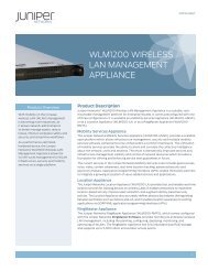
3-TIER LEGACY NETWORK<br />
Ethernet<br />
Figure 1: Multitier legacy data center <strong>LAN</strong><br />
<strong>Data</strong> <strong>Center</strong> <strong>LAN</strong> <strong>Migration</strong> <strong>Guide</strong><br />
<strong>Data</strong> <strong>Center</strong> Interconnect<br />
WAN Edge<br />
Aggregation Layer<br />
This multitiered architecture, shown in Figure 1, worked well in a client/server world where the traffic was primarily “north<br />
and south,” and oversubscription ratios at tiers of the network closest to the endpoints (including servers and storage)<br />
could be high. However, traffic flows and performance requirements have changed considerably with the advent of<br />
applications based on SOA, increased mobility, Web 2.0, unified communications, compliance requirements, and the<br />
sheer number of devices connecting to the corporate infrastructure. Building networks today to accommodate 5 to 10<br />
year old traffic patterns is not optimal, and results in lower performance, unnecessary complexity, and higher cost.<br />
A new data center network design is needed to maximize IT investment and easily scale to support the new<br />
applications and services a high-performance enterprise requires to stay competitive. According to Gartner,<br />
“Established <strong>LAN</strong> design practices were created for an environment of limited switch performance. Today’s highcapacity<br />
switches allow new design approaches, thus reducing cost and complexity in campus and data center <strong>LAN</strong>s.<br />
The three-tier concept can be discarded, because all switch ports can typically deliver rich functionality without<br />
impacting performance.” 1<br />
Copyright © 2012, <strong>Juniper</strong> <strong>Networks</strong>, Inc. 7<br />
Core<br />
Access Layer<br />
Servers NAS FC Storage<br />
FC SAN<br />
1 Neil Rikard “Minimize <strong>LAN</strong> Switch Tiers to Reduce Cost and Increase Efficiency,” Gartner Research ID Number: G00172149 November 17, 2009
<strong>Data</strong> <strong>Center</strong> <strong>LAN</strong> <strong>Migration</strong> <strong>Guide</strong><br />
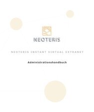
SRX5800<br />
GbE<br />
MX Series<br />
EX8216<br />
Servers<br />
Figure 2: Simpler two-tier data center <strong>LAN</strong> design<br />
<strong>Juniper</strong> <strong>Networks</strong> offers a next-generation data center solution, shown in Figure 2, which delivers:<br />
• Simplified design for high performance and ease of management<br />
• Scalable services and infrastructure to meet the needs of a high-performance enterprise<br />
• Virtualized resources to increase efficiency<br />
This two-tier data center <strong>LAN</strong> architecture provides a more elastic and more efficient network that can also easily scale.<br />
This guide covers the key considerations in migrating an existing three-tier data center network to a simplified, cloudready,<br />
two-tier design. From a practical perspective, most enterprises won’t initiate a complete data center redesign<br />
for an existing, operational data center. However, there are several events, such as bringing a new application or<br />
service online or a data center consolidation, which require an addition to the existing data center infrastructure. We<br />
call these common events at which migration can begin trigger events. Trigger events generate changes in design at a<br />
given network layer, which we call an insertion point. In Chapter 3 of this guide, we cover the best practices and steps<br />
involved for migration at each of the insertion points presented by a specific trigger event. By following these steps and<br />
practices, it is possible to extend migration to other legacy network tiers and continue towards a simplified two-tier<br />
<strong>Juniper</strong> infrastructure over time.<br />
In summary, this <strong>Data</strong> <strong>Center</strong> <strong>LAN</strong> <strong>Migration</strong> <strong>Guide</strong> describes:<br />
Core Layer<br />
QFX3500 Switch<br />
• Pre-migration information requirements<br />
• <strong>Migration</strong> process overview and design considerations<br />
• Logical migration steps and <strong>Juniper</strong> best practices for transitioning each network layer insertion point<br />
• Troubleshooting steps<br />
• Additional resources<br />
8 Copyright © 2012, <strong>Juniper</strong> <strong>Networks</strong>, Inc.<br />
FC<br />
NAS<br />
FC SAN<br />
FC Storage
Why Migrate?<br />
<strong>Data</strong> <strong>Center</strong> <strong>LAN</strong> <strong>Migration</strong> <strong>Guide</strong><br />
IT continues to become more tightly integrated with business across all industries and markets. Technology is the<br />
means by which enterprises can provide better access to information in near or real time to satisfy customer needs,<br />
while simultaneously driving new efficiencies. However, today’s enterprise network infrastructures face growing<br />
scalability, agility, and security challenges. This is due to factors such as increased collaboration with business<br />
partners, additional workforce mobility, and the sheer proliferation of users with smart mobile devices requiring<br />
constant access to information and services. These infrastructure challenges are seriously compounded when growth<br />
factors are combined with the trend towards data center consolidation. What is needed is a new network infrastructure<br />
that is more elastic, more efficient, and can easily scale.<br />
Scalability is a high priority, as it is safe to predict that much of the change facing businesses today is going to come as<br />
a requirement for more storage, more processing power, and more flexibility.<br />
Recent studies by companies such as IDC suggest that global enterprises will be focusing their investments and<br />
resources in the next 5 to 10 years on lowering costs while continuing to look for new growth areas. Industry analysts<br />
have identified several key data center business initiatives that align with these directions:<br />
• <strong>Data</strong> center consolidation: Enterprises combine data centers as a result of merger or acquisition to reduce cost as<br />
well as centralize and consolidate resources.<br />
• Virtualization: Server virtualization is used to increase utilization of CPU resources, provide flexibility, and deliver<br />
“on-demand” services that easily scale (currently the most prevalent virtualization example).<br />
• Cloud computing: Pooling resources within a cloud provides a cost-efficient way to reconfigure, reclaim, and reuse<br />
resources to deliver responsive services.<br />
• I/O convergence or consolidation: Ethernet and Fibre Channel are consolidated over a single wire on the server side.<br />
• Virtual Desktop Infrastructure (VDI): Applications are run on centralized servers to reduce operational costs and<br />
also provide greater flexibility.<br />
These key initiatives all revolve around creating greater data center efficiencies. While meeting these business<br />
requirements, it is vital that efficient solutions remain flexible and scalable systems are easy to manage to maximize<br />
all aspects of potential cost savings.<br />
In today’s data center, applications are constantly being introduced, updated, and retired. Demand for services is<br />
unpredictable and ever changing. Remaining responsive, and at the same time cost efficient, is a significant resource<br />
management challenge, and adding resources needs to be a last resort since it increases the cost basis for service<br />
production and delivery. Having the ability to dynamically reconfigure, reclaim, and reuse resources positions the data<br />
center to effectively address today’s responsiveness and efficiency challenges.<br />
Furthermore, existing three-tier architectures are built around a client/server model that is less relevant in today’s<br />
application environment. Clearly, a new data center <strong>LAN</strong> design is needed to adapt to changing network dynamics,<br />
overcome the complexity of scaling with the current multitiered architecture, as well as capitalize on the benefits of<br />
high-performance platforms and a simplified design.<br />
Copyright © 2012, <strong>Juniper</strong> <strong>Networks</strong>, Inc. 9
<strong>Data</strong> <strong>Center</strong> <strong>LAN</strong> <strong>Migration</strong> <strong>Guide</strong><br />
Network topologies should mirror<br />
the nature of the tra�c they transport<br />
N<br />
S<br />
UP TO 70%<br />
Figure 3: <strong>Data</strong> center traffic flows<br />
Applications built on SOA architecture and those delivered in the software as a service (SaaS) model require an<br />
increasing number of interactions among servers in the data center. These technologies generate a significant amount of<br />
server-to-server traffic; in fact, up to 70% of data center <strong>LAN</strong> traffic is between servers. Additional server traffic may also<br />
be produced by the increased adoption of virtualization, where shared resources such as a server pool are used at greater<br />
capacity to improve efficiency. Today’s network topologies need to mirror the nature of the traffic being transported.<br />
Existing three-tier architectures were not designed to handle server-to-server traffic without going up and back through<br />
the many layers of tiers. This is inherently inefficient, adding latency at each hop, which in turn impacts performance,<br />
particularly for real-time applications like unified communications, or in industries requiring high performance such as<br />
financial trading.<br />
Scaling Is Too Complex with Current <strong>Data</strong> <strong>Center</strong> Architectures<br />
Simply deploying ever more servers, storage, and devices in a three-tier architecture to meet demand significantly<br />
increases network complexity and cost. In many cases, it isn’t possible to add more devices due to space, power,<br />
cooling, or throughput constraints. And even when it is possible, it is often difficult and time-consuming to manage due<br />
to the size and scope of the network. Or it is inherently inefficient, as it’s been estimated that as much as 50% of all<br />
ports in a typical data center are used for connecting switches to each other as opposed to doing the more important<br />
task of interconnecting storage to servers and applications to users. Additionally, large Layer 2 domains using Spanning<br />
Tree Protocol (STP) are prone to failure and poor performance. This creates barriers to the efficient distribution of<br />
resources in the DC and fundamentally prevents a fast and flexible network scale out. Similarly, commonly deployed<br />
data center technologies like multicast don’t perform at scale across tiers and devices in a consistent fashion.<br />
Legacy security services may not easily scale and are often not efficiently deployed in a data center <strong>LAN</strong> due to the<br />
difficulty of incorporating security into a legacy,multitiered design. Security blades which are bolted into switches at the<br />
aggregation layer consume excessive power and space, impact performance, and don’t protect virtualized resources.<br />
Another challenge of legacy security service appliances is the limited performance scalability, which may be far<br />
below the throughput requirements of most high-performance enterprises consolidating applications or data centers.<br />
The ability to cluster together firewalls as a single logical entity to increase scalability without added management<br />
complexity is another important consideration.<br />
Proprietary systems may also limit further expansion with vendor lock-in to low performance equipment. Different<br />
operating systems at each layer may add to the complexity to operate and scale the network. This complexity is costly,<br />
limits flexibility, increases the time it takes to provision new capacity or services, and restricts the dynamic allocation of<br />
resources for services such as virtualization.<br />
10 Copyright © 2012, <strong>Juniper</strong> <strong>Networks</strong>, Inc.<br />
W<br />
E
The Case for a High Performing, Simplified Architecture<br />
<strong>Data</strong> <strong>Center</strong> <strong>LAN</strong> <strong>Migration</strong> <strong>Guide</strong><br />
Enhanced, high-performance <strong>LAN</strong> switch technology can help meet these scaling challenges. According to Network World,<br />
“Over the next few years, the old switching equipment needs to be replaced with faster and more flexible switches. This<br />
time, speed needs to be coupled with lower latency, abandoning spanning tree and support for the new storage protocols.<br />
Networking in the data center must evolve to a unified switching fabric.” 2<br />
New switching technology such as that found in <strong>Juniper</strong> <strong>Networks</strong> ® EX Series Ethernet Switches has caught up to<br />
meet or surpass the demands of even the most high-performance enterprise. Due to specially designed applicationspecific<br />
integrated circuits (ASICs) which perform in-device switching functions, enhanced switches now offer high<br />
throughput capacity of more than one terabit per second (Tbps) with numerous GbE and 10GbE ports, vastly improving<br />
performance and reducing the number of uplink connections. Some new switches also provide built-in virtualization<br />
that reduces the number of devices that must be managed, yet can rapidly scale with growth. Providing much greater<br />
performance, enhanced switches also enable the collapsing of unnecessary network tiers—moving towards a new,<br />
simplified network design. Similarly, scalable enhanced security devices can be added to complement such a design,<br />
providing security services throughout the data center <strong>LAN</strong>.<br />
A simplified, two-tier data center <strong>LAN</strong> design can lower costs without compromising performance. Built on highperformance<br />
platforms, a collapsed design requires fewer devices, thereby reducing capital outlay and the operational<br />
costs to manage the data center <strong>LAN</strong>. Having fewer network tiers also decreases latency and increases performance,<br />
enabling wider support of additional cost savings and high bandwidth applications such as unified communications.<br />
Despite having fewer devices, a simplified design still offers high availability (HA) with key devices being deployed in<br />
redundant pairs and dual homed to upstream devices. Additional HA is offered with features like redundant switching<br />
fabrics, dual power supplies, and the other resilient capabilities available in enhanced platforms.<br />
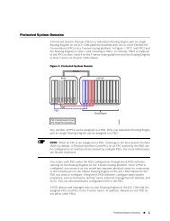
MULTI-TIER LEGACY NETWORK 2-TIER DESIGN<br />
Density<br />
Performance<br />
Reliability<br />
Figure 4: Collapsed network design delivers increased density, performance, and reliability<br />
2Robin Layland/Layland Consulting “10G Ethernet shakes Net Design to the Core/Shift from three- to two-tier architectures accelerating,” Network World<br />
September 14, 2009<br />
Copyright © 2012, <strong>Juniper</strong> <strong>Networks</strong>, Inc. 11
<strong>Data</strong> <strong>Center</strong> <strong>LAN</strong> <strong>Migration</strong> <strong>Guide</strong><br />
Two-Tier Design Facilitates Cloud Computing<br />
By simplifying the design, by sharing resources, and by allowing for integrated security, a two-tier design also enables<br />
the enterprise to take advantage of the benefits of cloud computing. Cloud computing delivers on-demand services to<br />
any point on the network without requiring the acquisition or provisioning of location-specific hardware and software.<br />
These cloud services are delivered via a centrally managed and consolidated infrastructure that has been virtualized.<br />
Standard data center elements such as servers, appliances, storage, and other networking devices can be arranged in<br />
resource pools that are shared securely across multiple applications, users, departments, or any other way they should<br />
be logically shared. The resources are dynamically allocated to accommodate the changing capacity requirements of<br />
different applications and improve asset utilization levels. This type of on-demand service and infrastructure simplifies<br />
management, reduces operating and ownership costs, and allows services to be provisioned with unprecedented<br />
speed. Reduced application and service delivery times mean that the enterprise is able to capitalize on opportunities<br />
as they occur.<br />
Achieving Power Savings and Operating Efficiencies<br />
Fewer devices require less power, which in turn reduces cooling requirements, thus adding up to substantial<br />
power savings. For example, a simplified design can offer more than a 39% power savings over a three-tier legacy<br />
architecture. Ideally, a common operating system should be used on all data center <strong>LAN</strong> devices to reduce errors,<br />
decrease training costs, ensure consistent features, and thus lower the cost of operating the network.<br />
Consolidating <strong>Data</strong> <strong>Center</strong>s<br />
Due to expanding services, enterprises often have more than one data center. Virtualization technologies like server<br />
migration and application load balancing require multiple data centers to be virtually consolidated into a single, logical<br />
data center. Locations need to be transparently interconnected with <strong>LAN</strong> interconnect technologies such as virtual<br />
private <strong>LAN</strong> service (VPLS) to interoperate and appear as one.<br />
All this is possible with a new, simplified data center <strong>LAN</strong> design from <strong>Juniper</strong> <strong>Networks</strong>. However, as stated earlier,<br />
<strong>Juniper</strong> recognizes that it is impractical to flash migrate from an existing, operational, three-tier production data center<br />
<strong>LAN</strong> design to a simpler two-tier design, regardless of the substantial benefits. However, migration can begin as a result<br />
of any of the following trigger events:<br />
• Addition of a new application or service<br />
• Refresh cycle<br />
• Server virtualization migration<br />
• <strong>Data</strong> center consolidation<br />
• Business continuity and workload mobility initiatives<br />
• <strong>Data</strong> center core network upgrade<br />
• Higher performance and scalability for security services<br />
The design considerations and steps for initiating migration from any of these trigger events is covered in detail in<br />
Chapter 3: <strong>Data</strong> <strong>Center</strong> <strong>Migration</strong>—Trigger Events and Deployment Processes.<br />
12 Copyright © 2012, <strong>Juniper</strong> <strong>Networks</strong>, Inc.
Why <strong>Juniper</strong>?<br />
<strong>Data</strong> <strong>Center</strong> <strong>LAN</strong> <strong>Migration</strong> <strong>Guide</strong><br />
<strong>Juniper</strong> delivers high-performance networks that are open to and embrace third-party partnerships to lower total cost<br />
of ownership (TCO) as well as to create flexibility and choice. <strong>Juniper</strong> is able to provide this based on its extensive<br />
investment in software, silicon, and systems.<br />
• Software: <strong>Juniper</strong>’s investment in software starts with <strong>Juniper</strong> <strong>Networks</strong> Junos ® operating system. Junos OS offers<br />
the advantage of one operating system with one release train and one modular architecture across the enterprise<br />
portfolio. This results in feature consistency and simplified management throughout all platforms in the network.<br />
• Silicon: <strong>Juniper</strong> is one of the few network vendors that invests in ASICs which are optimized for Junos OS to<br />
maximize performance and resiliency.<br />
• Systems: The combination of the investment in ASICs and Junos OS produces high-performance systems that<br />
simultaneously scale connectivity, capacity, and the control capability needed to deliver new applications and<br />
business processes on a single infrastructure that also reduces application and service delivery time.<br />
<strong>Juniper</strong>’s strategy for simplifying the data center network is called the 3-2-1 <strong>Data</strong> <strong>Center</strong> Network Architecture, which<br />
eliminates layers of switching to “flatten” and collapse the network from today’s three-tier tree structure to two<br />
layers, and in the future just one (see Figure 5). A key enabler of this simplification is achieved by deploying <strong>Juniper</strong>’s<br />
Virtual Chassis fabric technology, which interconnects multiple physical switches to create a single, logical device that<br />
combines the performance and simplicity of a switch with the connectivity and resiliency of a network. Organizations<br />
can migrate from a three-tier to a two-tier network beginning with a Trigger Event such as adding a new POD or a<br />
technology refresh. <strong>Migration</strong> Trigger Events will be presented in more detail in Chapter 3. Alternatively, they can<br />
move directly into a <strong>Juniper</strong>-enabled data center fabric as it becomes available. Creating a simplified infrastructure<br />
with shared resources and secure services delivers significant advantages over other designs. It helps lower costs,<br />
increase efficiency, and keep the data center agile enough to accommodate any future business changes or technology<br />
infrastructure requirements. The steps to migrate from an existing three-tier network to a flatter design, as articulated<br />
by the <strong>Juniper</strong> <strong>Networks</strong> 3-2-1 <strong>Data</strong> <strong>Center</strong> Network Architecture, is built on four core principles:<br />
• Simplify the architecture: Consolidating legacy siloed systems and collapsing inefficient tiers results in fewer<br />
devices, a smaller operational footprint, and simplified management from a “single pane of glass.”<br />
• Share the resources: Segmenting the network into simple, logical, and scalable partitions with privacy, flexibility,<br />
high performance, and quality of service (QoS) enables network agility to rapidly adapt to an increasing number of<br />
users, applications, and services.<br />
• Secure the data flows: Integrating scalable, virtualized security services into the network core provides benefits to all<br />
users and applications. Comprehensive protection secures data flows into, within, and between data centers. It also<br />
provides centralized management and the distributed dynamic enforcement of application and identity-aware policies.<br />
• Automate network operations at each step—An open, extensible software platform reduces operational costs<br />
and complexity, enables rapid scaling, minimizes operator errors, and increases reliability through a single network<br />
operating system. A powerful network application platform with innovative applications enables network operators<br />
to leverage <strong>Juniper</strong> or third-party applications for simplifying operations and scaling application infrastructure to<br />
improve operational efficiency.<br />
Copyright © 2012, <strong>Juniper</strong> <strong>Networks</strong>, Inc. 13
<strong>Data</strong> <strong>Center</strong> <strong>LAN</strong> <strong>Migration</strong> <strong>Guide</strong><br />
3.<br />
Legacy three-tier<br />
data center<br />
W Up to 75% of tra�c E<br />
Figure 5: <strong>Juniper</strong> <strong>Networks</strong> 3:2:1 <strong>Data</strong> <strong>Center</strong> Network Architecture<br />
<strong>Juniper</strong>’s data center <strong>LAN</strong> architecture embodies these principles and enables high-performance enterprises to build<br />
next-generation, cloud-ready data centers. For information on Building the Cloud-Ready <strong>Data</strong> <strong>Center</strong>, please refer to:<br />
www.juniper.net/us/en/solutions/enterprise/data-center.<br />
Other Considerations<br />
2.<br />
<strong>Juniper</strong> two-tier<br />
data center<br />
W Up to 75% of tra�c E<br />
<strong>Juniper</strong>’s data<br />
center fabric<br />
It is interesting to note that even as vendors introduce new product lines, the legacy three-tier architecture remains as<br />
the reference architecture for <strong>Data</strong> <strong>Center</strong>s. This legacy three-tier architecture retains the same limitations in terms of<br />
scalability and increased complexity.<br />
Additionally, migrating to a new product line, even with an incumbent vendor, may require adopting a new OS,<br />
modifying configurations, and replacing hardware. The potential operational impact of introducing new hardware<br />
is a key consideration for insertion into an existing data center infrastructure, regardless of the platform provider.<br />
Prior to specific implementation at any layer of the network, it is sound practice to test interoperability and feature<br />
consistency in terms of availability and implementation. When considering an incumbent vendor with a new platform,<br />
any Enterprise organization weighing migration to a new platform from their existing one, should also evaluate moving<br />
towards a simpler high performing <strong>Juniper</strong>-based solution, which can deliver substantial incremental benefits. (See<br />
Chapter 3: <strong>Data</strong> <strong>Center</strong> <strong>Migration</strong>—Trigger Events and Deployment Processes for more details about introducing a<br />
second switching infrastructure vendor into an existing single vendor network.)<br />
In summary, migrating to a simpler data center design enables an enterprise to improve the end user experience and<br />
scale without complexity, while also driving down operational costs.<br />
14 Copyright © 2012, <strong>Juniper</strong> <strong>Networks</strong>, Inc.<br />
1.
<strong>Data</strong> <strong>Center</strong> <strong>LAN</strong> <strong>Migration</strong> <strong>Guide</strong><br />
Chapter 2:<br />
Pre-<strong>Migration</strong> Information<br />
Requirements<br />
Copyright © 2012, <strong>Juniper</strong> <strong>Networks</strong>, Inc. 15
<strong>Data</strong> <strong>Center</strong> <strong>LAN</strong> <strong>Migration</strong> <strong>Guide</strong><br />
Pre-<strong>Migration</strong> Information Requirements<br />
Migrating towards a simplified design is based on a certain level of familiarity with the following <strong>Juniper</strong> solutions:<br />
• <strong>Juniper</strong> <strong>Networks</strong> Junos operating system<br />
• <strong>Juniper</strong> <strong>Networks</strong> EX Series Ethernet Switches and MX Series 3D Universal Edge Routers<br />
• <strong>Juniper</strong> <strong>Networks</strong> SRX Series Services Gateways<br />
• <strong>Juniper</strong> <strong>Networks</strong> Network and Security Manager, STRM Series Security Threat Response Managers, and Junos Space<br />
network management solutions<br />
<strong>Juniper</strong> <strong>Networks</strong> Cloud-Ready <strong>Data</strong> <strong>Center</strong> Reference Architecture communicates <strong>Juniper</strong>’s conceptual framework and<br />
architectural philosophy in creating data center and cloud computing networks robust enough to serve the range of<br />
customer environments that exist today. It can be downloaded from: www.juniper.net/us/en/solutions/enterprise/<br />
data-center/simplify/#literature.<br />
Technical Knowledge and Education<br />
This <strong>Migration</strong> <strong>Guide</strong> assumes some experience with Junos OS and its rich tool set, which will not only help simplify<br />
the data center <strong>LAN</strong> migration but also ongoing network operations. A brief overview of Junos OS is provided in the<br />
following section. <strong>Juniper</strong> also offers a comprehensive series of Junos OS workshops. Standardization of networking<br />
protocols should ease the introduction of Junos OS into the data center since the basic constructs are similar. <strong>Juniper</strong><br />
<strong>Networks</strong> offers a rich curriculum of introductory and advanced courses on all of its products and solutions.<br />
Learn more about <strong>Juniper</strong>’s free and fee-based online and instructor-led hands-on training offerings at:<br />
www.juniper.net/us/en/training/technical_education.<br />
Additional education may be required for migrating security services such as firewall and intrusion prevention system (IPS).<br />
If needed, <strong>Juniper</strong> <strong>Networks</strong> Professional Services can provide access to industry-leading IP experts to help with all<br />
phases of the design, planning, testing, and migration process. These experts are also available as training resources,<br />
to help with project management, risk assessment, and more. The full suite of <strong>Juniper</strong> <strong>Networks</strong> Professional Services<br />
offerings can be found at: www.juniper.net/us/en/products-services/consulting-services.<br />
Junos OS Overview<br />
Enterprises deploying legacy-based solutions today are most likely familiar with the number of different operating<br />
systems (OS versions) running on switching, security, and routing platforms. This can result in feature inconsistencies,<br />
software instability, time-consuming fixes and upgrades. It’s not uncommon for a legacy data center to be running<br />
many different versions of a switching OS, which may increase network downtime and require greater time, effort, and<br />
cost to manage the network. From its beginning, <strong>Juniper</strong> set out to create an operating system that addressed these<br />
common problems. The result is Junos OS, which offers one consistent operating system across all of <strong>Juniper</strong>’s routing,<br />
switching, and security devices.<br />
16 Copyright © 2012, <strong>Juniper</strong> <strong>Networks</strong>, Inc.
Junos Pulse<br />
SRX5000 Line<br />
SRX3000 Line<br />
Figure 6: Junos OS - The power of one<br />
<strong>Data</strong> <strong>Center</strong> <strong>LAN</strong> <strong>Migration</strong> <strong>Guide</strong><br />
Junos OS serves as the foundation of a highly reliable network infrastructure and has been at the core of the world’s<br />
largest service provider networks for over 10 years. Junos OS offers identical carrier-class performance and reliability<br />
to any sized enterprise data center <strong>LAN</strong>. Also through open, standards-based protocols and an API, Junos OS can be<br />
customized to optimize any enterprise-specific requirement.<br />
What sets Junos OS apart from other network operating systems is the way it is built: one operating system (OS)<br />
delivered in one software release train, and with one modular architecture. Feature consistency across platforms and<br />
one predictable release of new features ensure compatibility throughout the data center <strong>LAN</strong>. This reduces network<br />
management complexity, increases network availability, and enables faster service deployment, lowering TCO and<br />
providing greater flexibility to capitalize on new business opportunities.<br />
Junos OS’ consistent user experience and automated tool sets make planning and training easier and day-to-day<br />
operations more efficient, allowing for faster changes. Further, integrating new software functionality protects not just<br />
hardware investments, but also an organization’s investment in internal systems, practices, and knowledge.<br />
Junos OS Architecture<br />
Junos Space<br />
T Series<br />
MX Series<br />
SRX240<br />
SRX100 SRX210 J Series<br />
M Series<br />
LN1000<br />
Branch<br />
SRX650<br />
10.3<br />
Frequent Releases<br />
One Release Track<br />
Module<br />
X<br />
One Architecture<br />
The Junos OS architecture is a modular design conceived for flexible yet stable innovation across many networking<br />
functions and platforms. The architecture’s modularity and well-defined interfaces streamline new development and<br />
enable complete, holistic integration of services.<br />
Copyright © 2012, <strong>Juniper</strong> <strong>Networks</strong>, Inc. 17<br />
10.4<br />
11.1<br />
EX8216<br />
EX8208<br />
EX4500 Line<br />
SECURITY ROUTERS SWITCHES<br />
One OS<br />
Core<br />
NSM<br />
NSMXpress<br />
EX4200 Line<br />
EX3200 Line<br />
EX2200 Line<br />
QFX3500<br />
— API —
<strong>Data</strong> <strong>Center</strong> <strong>LAN</strong> <strong>Migration</strong> <strong>Guide</strong><br />
CONTROL P<strong>LAN</strong>E<br />
DATA P<strong>LAN</strong>E<br />
Figure 7: The modular Junos OS architecture<br />
The advantages of modularity reach beyond the operating system software’s stable, evolutionary design. For example,<br />
the Junos OS architecture’s process modules run independently in their own protected memory space, so one module<br />
cannot disrupt another. The architecture also provides separation between control and forwarding functions to support<br />
predictable high performance with powerful scalability. This separation also hardens Junos OS against distributed<br />
denial-of-service (DDoS) attacks. Junos operating system’s modularity is integral to the high reliability, performance,<br />
and scalability delivered by its software design. It enables unified in-service software upgrade (ISSU), graceful Routing<br />
Engine switchover (GRES), and nonstop routing.<br />
Automated Scripting with Junoscript Automation<br />
Management<br />
CLI<br />
Scripts<br />
Routing<br />
OPEN MANAGEMENT INTERFACES<br />
Interfaces<br />
Kernel<br />
NSM/<br />
Junos Space<br />
Packet Forwarding<br />
Physical Interfaces<br />
Service<br />
App 1<br />
Service<br />
App 2<br />
Service<br />
App 3<br />
Service<br />
App n<br />
With Junoscript Automation, experienced engineers can create scripts that reflect their own organization’s needs and<br />
procedures. The scripts can be used to flag potential errors in basic configuration elements such as interfaces and<br />
peering. The scripts can also automate network troubleshooting and quickly detect, diagnose, and fix problems as<br />
they occur. In this way, new personnel running the scripts benefit from their predecessors’ long-term knowledge and<br />
expertise. <strong>Networks</strong> using Junoscript Automation can increase productivity, reduce OpEx, and increase high availability<br />
(HA), since the most common reason for a network outage is operator error.<br />
For more detailed information on Junos Script Automation, please see: www.juniper.net/us/en/community/junos.<br />
18 Copyright © 2012, <strong>Juniper</strong> <strong>Networks</strong>, Inc.<br />
Module n<br />
J-Web<br />
Services Interfaces<br />
Toolkit<br />
SERVICES P<strong>LAN</strong>E
<strong>Data</strong> <strong>Center</strong> <strong>LAN</strong> <strong>Migration</strong> <strong>Guide</strong><br />
A key benefit of using Junos OS is lower TCO as a result of reduced operational challenges and improved operational<br />
productivity at all levels in the network.<br />
Switch<br />
and Router<br />
Downtime<br />
Costs<br />
27%*<br />
Lower<br />
with<br />
Junos<br />
(Based on reduction<br />
in frequency and<br />
duration of<br />
unplanned<br />
network events)<br />
Figure 8: Junos OS lowers operations costs across the data center<br />
An independent commissioned study conducted by Forrester Consulting3 (www.juniper.net/us/en/reports/junos_tei.pdf)<br />
found that the use of Junos OS and <strong>Juniper</strong> platforms produced a 41% reduction in overall operations costs for network<br />
operational tasks including planning and provisioning, deployment, and planned and unplanned network events.<br />
<strong>Juniper</strong> Platform Overview<br />
The ability to migrate from a three-tier network design to a simpler two-tier design with increased performance,<br />
scalability, and simplicity is predicated on the availability of hardware-based services found in networking platforms<br />
such as the EX Series Ethernet Switches, MX Series 3D Universal Edge Routers, and the SRX Series Services Gateways.<br />
A consistent and unified view of the data center, campus, and branch office networks is provided by <strong>Juniper</strong>’s “single<br />
pane of glass” management platforms, including the recently introduced Junos Space.<br />
The following section provides a brief overview of the capabilities of <strong>Juniper</strong>’s platforms. All of the Junos OS-based<br />
platforms highlighted provide feature consistency throughout the data center <strong>LAN</strong> and lower TCO.<br />
EX4200 Switch with Virtual Chassis Technology<br />
Critical Categories of Enterprise Network Operational Costs<br />
Switch and<br />
Router<br />
Maintenance<br />
and Support<br />
Costs<br />
Baseline for all network operating systems<br />
54%*<br />
Lower<br />
with<br />
Junos<br />
(A “planned<br />
events”<br />
category)<br />
Switch and<br />
Router<br />
Deployment<br />
Time Costs<br />
25%*<br />
Lower<br />
with<br />
Junos<br />
(The “adding<br />
infrastructure”<br />
task)<br />
Unplanned<br />
Switch and<br />
Router<br />
Events<br />
Resolution<br />
Costs<br />
40%*<br />
Lower<br />
with<br />
Junos<br />
(The time needed to<br />
resolve unplanned<br />
network events)<br />
Multiple network operating systems diminish e�ciency 3<br />
Overall<br />
Switch<br />
and Router<br />
Network<br />
Operations<br />
Costs<br />
41%*<br />
Lower<br />
with<br />
Junos<br />
(The combined total<br />
savings associated<br />
with planned,<br />
unplanned, planning<br />
and provisioning,<br />
and adding<br />
infrastructure tasks)<br />
Typically deployed at the access layer in a data center, <strong>Juniper</strong> <strong>Networks</strong> EX4200 Ethernet Switch provides chassisclass,<br />
high availability features, and high-performance throughput in a pay as you grow 1 rack unit (1 U) switch.<br />
Depending on the size of the data center, the EX4200 may also be deployed at the aggregation layer. Offering flexible<br />
cabling options, the EX4200 can be located at the top of a rack or end of a row. There are several different port<br />
configurations available with each EX4200 switch, providing up to 48 wire-speed, non-blocking, 10/100/1000 ports<br />
with full or partial Power over Ethernet (PoE). Despite its small size, this high-performance switch also offers multiple<br />
GbE or 10Gbe uplinks to the core, eliminating the need for an aggregation layer. And because of its small size, it takes<br />
less space, requires less power and cooling, and it costs less to deploy and maintain sparing.<br />
Up to 10 EX4200 line switches can be connected, configured, and managed as one single logical device through built-in<br />
Virtual Chassis technology. The actual number deployed in a single Virtual Chassis instance depends upon the physical<br />
layout of your data center and the nature of your traffic. Connected via a 128 Gbps backplane, a Virtual Chassis can be<br />
comprised of EX4200 switches within a rack or row, or it can use a 10GbE connection anywhere within a data center or<br />
across data centers up to 40 km apart.<br />
3 “The Total Economic Impact of Junos Network Operating Systems”, a commissioned study conducted by Forrester Consulting on behalf of <strong>Juniper</strong> <strong>Networks</strong>,<br />
February 2009<br />
Copyright © 2012, <strong>Juniper</strong> <strong>Networks</strong>, Inc. 19
<strong>Data</strong> <strong>Center</strong> <strong>LAN</strong> <strong>Migration</strong> <strong>Guide</strong><br />
<strong>Juniper</strong>’s Virtual Chassis technology enables virtualization at the access layer, offering three key benefits:<br />
1. It reduces the number of managed devices by a factor of 10X.<br />
2. The network topology now closely maps to the traffic flow. Rather than sending inter-server traffic up to an<br />
aggregation layer and then back down in order to send it across the rack, it’s sent directly “east-to-west,” reducing<br />
the latency for these transactions. This also more easily facilitates workload mobility when server virtualization is<br />
deployed.<br />
3. Since the network topology now maps to the traffic flows directly, the number of uplinks required can be reduced.<br />
The Virtual Chassis also delivers best-in-class performance. According to testing done by Network World (see full<br />
report at www.networkworld.com/slideshows/2008/071408-juniper-ex4200.html), the EX4200 offers the lowest<br />
latency of any Ethernet switch they had tested, making the EX4200 an optimal solution for high-performance, low<br />
latency, real-time applications. There has also been EX4200 performance testing done in May 2010 by Network Test<br />
which demonstrates the low latency high performance and high availability capabilities of the EX 4200 series, viewable<br />
at http://networktest.com/jnprvc.<br />
When multiple EX4200 platforms are connected in a Virtual Chassis configuration, they offer the same software high<br />
availability as traditional chassis-based platforms. Each Virtual Chassis has a master and backup Routing Engine preelected<br />
with synchronized routing tables and routing protocol states for rapid failover should a master switch fail. The<br />
EX4200 line also offers fully redundant power and cooling.<br />
To further lower TCO, <strong>Juniper</strong> includes core routing features such as OSFP and RIPv2 in the base software license,<br />
providing a no incremental cost option for deploying Layer 3 at the access layer.<br />
In every deployment, the EX4200 reduces network configuration burdens and measurably improves performance for<br />
server-to-server communications in SOA, Web services, and other distributed application designs.<br />
For more information, refer to the EX4200 Ethernet Switch data sheet for a complete list of features, benefits, and<br />
specifications at: www.juniper.net/us/en/products-services/switching/ex-series.<br />
QFX3500<br />
QFabric consists of edge, interconnect, and control devices that work together to create a high-performance, low<br />
latency fabric that unleashes the power of the data center. QFabric represents the “1” in <strong>Juniper</strong> <strong>Networks</strong> 3-2-1<br />
architecture, dramatically reducing complexity in the data center by delivering any-to-any connectivity while lowering<br />
capital, management, and operational expenses.<br />
The first QFabric product, the <strong>Juniper</strong> <strong>Networks</strong> QFX3500 represents a new level of integration and performance for<br />
top of rack switches by being the first to combine all of the following in 1 RU.<br />
• Ultra Low Latency - matching industry best latency for a 48+ port Ethernet switch<br />
• L2 – full L2 switching functionality<br />
• L3 – routing and IP addressing functions (Future)<br />
• Storage convergence – Ethernet storage (NAS, iSCSI, FCoE)and Fibre Channel gateway<br />
• 40G – high capacity uplinks (Future)<br />
Refer to the QFX3500 data sheet for more information at:<br />
www.juniper.net/us/en/local/pdf/datasheets/1000361-en.pdf<br />
EX4500 10GbE Switch<br />
The <strong>Juniper</strong> <strong>Networks</strong> EX4500 Ethernet Switch delivers a scalable, compact, high-performance platform for supporting<br />
a mix of GbE and high-density 10 gigabit per second (10 Gbps) data center top-of-rack, as well as data center, campus,<br />
and service provider aggregation deployments. The QFX3500 is the preferred platform for 10 Gigabit per second Top<br />
of Rack Deployments. The Junos OS-based EX4500 is a 48 port wire-speed switch whose ports can be provisioned as<br />
either gigabit Ethernet (GbE) or 10GbE ports in a two rack unit (2 U) form factor. The 48 ports are allocated with 40<br />
1000BaseT ports in the base unit and 8 optional uplink module ports. The EX4500 delivers 960 Gbps throughput (full<br />
duplex) for both Layer 2 and Layer 3 protocols. The EX4500 also supports Virtual Chassis technology.<br />
20 Copyright © 2012, <strong>Juniper</strong> <strong>Networks</strong>, Inc.
<strong>Data</strong> <strong>Center</strong> <strong>LAN</strong> <strong>Migration</strong> <strong>Guide</strong><br />
For smaller data centers, the EX4500 can be deployed as the core layer switch, aggregating 10GbE uplinks from<br />
EX4200 Virtual Chassis configurations in the access layer. Back-to-front and front-to-back cooling ensure consistency<br />
with server designs for hot and cold aisle deployments.<br />
<strong>Juniper</strong> plans to add support to the EX4500 for <strong>Data</strong> <strong>Center</strong> Bridging and Fibre Channel over Ethernet(FCoE) in<br />
upcoming product releases, providing FCoE Transit Switch Functionality.<br />
Refer to the EX4500 Ethernet Switch data sheet for more information at: www.juniper.net/us/en/products-services/<br />
switching/ex-series/ex4500/#literature.<br />
The QFX3500 would be the preferred platform for those organizations that are building out a high density 10 Gigabit<br />
<strong>Data</strong> <strong>Center</strong>. It is also a building block towards the single <strong>Data</strong> <strong>Center</strong> Fabric which <strong>Juniper</strong> will be providing in the<br />
future. For <strong>Data</strong> <strong>Center</strong> architectures where there is a mix of primarily Gigabit and 10 Gigabit, the EX4500 would be the<br />
appropriate platform.<br />
EX8200 Line of Ethernet Switches<br />
The <strong>Juniper</strong> <strong>Networks</strong> EX8200 line of Ethernet switches is a high-performance chassis platform designed for the high<br />
throughput that a collapsed core layer requires. This highly scalable platform supports up to 160,000 media access<br />
control (MAC) addresses, 64,000 access control lists (ACLs), and wire-rate multicast replication. The EX8200 line<br />
may also be deployed as an end-of-rack switch for those enterprises requiring a dedicated modular chassis platform.<br />
The advanced architecture and capabilities of the EX8200 line, similar to the EX4200, accelerate migration towards a<br />
simplified data center design.<br />
The EX8200-40XS line card brings 10GbE to the access layer for end-of-row configurations. This line card will deliver<br />
25 percent greater density per chassis and consume half the power of competing platforms, reducing rack space and<br />
management costs. With the 40-port line card, the EX8200 line with Virtual Chassis technology enables a common<br />
fabric of more than 2,500 10GbE ports.<br />
The most fundamental challenge that data center managers face is the challenge of physical plant limitations. In this<br />
environment, taking every step possible to minimize power draw for the required functionality becomes a critical goal.<br />
For data center operators searching for the most capable equipment in terms of functionality for the minimum in rack<br />
space, power, and cooling, the EX8200 line delivers higher performance and scalability in less rack space with lower<br />
power consumption than competing platforms.<br />
Designed for carrier-class HA, each EX8200 line model also features fully redundant power and cooling, fully<br />
redundant Routing Engines, and N+1 redundant switch fabrics.<br />
For more information, refer to the EX8200 line data sheets for a complete list of features and specifications at:<br />
www.juniper.net/us/en/products-services/switching/ex-series.<br />
MX Series 3D Universal Edge Routers<br />
It’s important to have a consistent set of powerful edge services routers to be able to interconnect the data center to<br />
other data centers and out to dispersed users. The MX Series with the Trio chipset delivers cost-effective, powerful<br />
scaling that allows enterprises to support application-level replication for disaster recovery or virtual machine migration<br />
between data centers by extending V<strong>LAN</strong>s across data centers using mature, proven technologies such as VPLS.<br />
It is interesting to note the following observation from the recent 2010 MPLS Ethernet World Conference from the Day 3<br />
<strong>Data</strong> <strong>Center</strong> Interconnect session: “VPLS is the most mature technology today to map DCI requirements”.<br />
Delivering carrier-class HA, each MX Series model features fully redundant power and cooling, fully redundant Routing<br />
Engines, and N+1 redundant switch fabrics.<br />
For more information, refer to the MX Series data sheet for a complete list of features, benefits, and specifications at:<br />
www.juniper.net/us/en/products-services/routing/mx-series.<br />
Copyright © 2012, <strong>Juniper</strong> <strong>Networks</strong>, Inc. 21
<strong>Data</strong> <strong>Center</strong> <strong>LAN</strong> <strong>Migration</strong> <strong>Guide</strong><br />
Consolidated Security with SRX Series Services Gateways<br />
The SRX Series Services Gateways replace numerous legacy security solutions by providing a suite of services in one<br />
platform, including a firewall, IPS, and VPN services.<br />
Supporting the concept of zones, the SRX Series can provide granular security throughout the data center <strong>LAN</strong>. The<br />
SRX Series can be virtualized and consolidated into a single pool of security services via clustering. The SRX Series<br />
can scale up to 10 million concurrent sessions allowing the SRX Series to massively and rapidly scale to handle any<br />
throughput without additional devices, multiple cumbersome device configurations, or operating systems.<br />
The highly scalable performance capabilities of the SRX Series platform, as with the EX Series switches, lays the<br />
groundwork for a simplified data center infrastructure and enable enterprises to easily scale to meet future growth<br />
requirements. This is in contrast to legacy integrated firewall modules and standalone appliances which have limited<br />
performance scalability. Even when multiple firewall modules are used, the aggregate performance may still be far<br />
below the throughput required for consolidating applications or data centers, where firewall aggregate throughput of<br />
greater than 100 gigabits may be required. The lack of clustering capabilities in some legacy firewalls not only limits<br />
performance scalability but also increases management and network complexity.<br />
The SRX Series provides HA features such as redundant power supplies and cooling fans, as well as redundant switch<br />
fabrics. This robust platform also delivers carrier-class throughput. The SRX5600 is the industry’s fastest firewall and<br />
IPS by a large margin, according to Network World.<br />
For more information, refer to the SRX Series data sheet for a complete list of features, benefits, and specifications at:<br />
www.juniper.net/us/en/products-services/security/srx-series.<br />
<strong>Juniper</strong> <strong>Networks</strong> vGW Virtual Gateway<br />
To address the unique security challenges of virtualized networks and data centers, the vGW virtual firewall and cloud<br />
protection software provides network and application visibility and granular control over virtual machines (VM).<br />
Combining a powerful stateful virtual firewall, VM Introspection and automated compliance assessment, the vGW<br />
Virtual Gateway protecting virtualized workloads slipstreams easily into <strong>Juniper</strong> environments featuring any of the<br />
following:<br />
• SRX Series Services Gateways<br />
• STRM Series Security Threat Response Managers<br />
• IDP Series Intrusion Detection and Prevention Appliances<br />
The vGW integrations focus on preserving customers’ investment into <strong>Juniper</strong> security, and extending it to the<br />
virtualized infrastructure with the similar feature, functionality, and enterprise-grade requirements like highperformance,<br />
redundancy, and central management.<br />
<strong>Juniper</strong> customers can deploy the vGW software on the virtualized server, and integrate security policies, logs, and<br />
related work flow into existing SRX Series, STRM Series, and IDP Series infrastructure. Customers benefit from layered,<br />
granular security without the management and OpEx overhead. vGW will export firewall logs and inter-VM traffic flow<br />
information to STRM Series to deliver ‘single-pane’ of glass for threat management. Customers who have deployed<br />
<strong>Juniper</strong> <strong>Networks</strong> IDP Series, and management processes around threat detection and mitigation can extend that to<br />
the virtualized server infrastructure with no additional CapEx investment.<br />
The vGW Virtual Gateway’s upcoming enhancements with SRX Series and Junos Space continues on the vision to<br />
deliver ‘gapless’ security with a common management platform. The vGW-SRX Series integration will ensure trust zone<br />
integrity is guaranteed to the last mile - particularly relevant in cloud and shared-infrastructure deployments. vGW<br />
integration with Junos Space will bridge the gap between management of physical resources and virtual resources to<br />
provide a comprehensive view of the entire data center.<br />
Refer to the vGW Virtual Gateway datasheet for more:<br />
www.juniper.net/us/en/local/pdf/datasheets/1000363-en.pdf.<br />
22 Copyright © 2012, <strong>Juniper</strong> <strong>Networks</strong>, Inc.
MPLS/VPLS for <strong>Data</strong> <strong>Center</strong> Interconnect<br />
<strong>Data</strong> <strong>Center</strong> <strong>LAN</strong> <strong>Migration</strong> <strong>Guide</strong><br />
The consolidation of network services increases the need for <strong>Data</strong> <strong>Center</strong> Interconnect (DCI). Resources in one data<br />
center are often accessed by one or more data centers. Different business units, for example, may share information<br />
across multiple data centers via VPNs. Or compliance regulations may require that certain application traffic be kept<br />
on separate networks throughout data centers. Or businesses may need a real-time synchronized standby system to<br />
provide optimum HA in a service outage.<br />
MPLS is a suite of protocols developed to add transport and virtualization capabilities to large data center networks.<br />
MPLS enables enterprises to scale their topologies and services. An MPLS network is managed using familiar protocols<br />
such as OSPF or Integrated IS-IS and BGP.<br />
MPLS provides complementary capabilities to standard IP routing. Moving to an MPLS network provides business<br />
benefits like improved network availability, performance, and policy enforcement. MPLS networks can be employed for<br />
a variety of reasons:<br />
• Inter <strong>Data</strong> <strong>Center</strong> Transport: To connect consolidated data centers to support mission critical applications. For<br />
example, real-time mainframe replication or disk, database, or transaction mirroring.<br />
• Virtualizing the Network Core: For logically separating network services. For example, providing different levels of<br />
QoS for certain applications or separate application traffic due to compliance requirements.<br />
• Extending L2VPNs for <strong>Data</strong> <strong>Center</strong> Interconnect: To extend L2 domains across data centers using VPLS. For example,<br />
to support application mobility with virtualization technologies like VMware VMotion, or to provide resilient business<br />
continuity for HA by copying transaction information in real time to another set of servers in another data center.<br />
The MX Series provides high capacity MPLS and VPLS technologies. MPLS networks can also facilitate migration<br />
towards a simpler, highly scalable and flexible data center infrastructure.<br />
<strong>Juniper</strong>’s Unified Management Solution<br />
<strong>Juniper</strong> provides three powerful management solutions for the data center <strong>LAN</strong> via its NSM and STRM Series platforms,<br />
as well as Junos Space.<br />
For more information on MPLS/VPLS, please refer to the “Implementing VPLS for <strong>Data</strong> <strong>Center</strong> Interconnectivity”<br />
Implementation <strong>Guide</strong> at: www.juniper.net/us/en/solutions/enterprise/data-center/simplify/#literature.<br />
Network and Security Manager<br />
NSM offers a single pane of glass to manage and maintain <strong>Juniper</strong> platforms as the network grows. It also helps<br />
maintain and configure consistent routing and security policies across the entire network. And NSM helps delegate<br />
roles and permissions as well.<br />
Delivered as a software application or a network appliance, NSM provides many benefits:<br />
• Centralized activation of routers, switches, and security devices<br />
• Granular role-based access and policies<br />
• Global policies and objects<br />
• Monitoring and investigative tools<br />
• Scalable and deployable solutions<br />
• Reliability and redundancy<br />
• Lower TCO<br />
Copyright © 2012, <strong>Juniper</strong> <strong>Networks</strong>, Inc. 23
<strong>Data</strong> <strong>Center</strong> <strong>LAN</strong> <strong>Migration</strong> <strong>Guide</strong><br />
The comprehensive NSM solution provides full life cycle management for all platforms in the data center <strong>LAN</strong>.<br />
• Deployment: Provides a number of options for adding device configurations into the database, such as importing a<br />
list of devices, or discovering and importing deployed network devices, or manually adding a device and configuration<br />
in NSM, or having the device contact NSM to add its configuration to the database.<br />
• Configuration: Offers central configuration to view and edit all managed devices. Provides offline editing/modeling<br />
of device configuration. Facilitates the sharing of common configurations across devices via templates and policies.<br />
Provides configuration file management for backup, versioning, configuration comparisons, and more.<br />
• Monitoring: Provides centralized event log management with predefined and user-customizable reports. Provides<br />
tools for auditing log trends and finding anomalies. Provides automatic network topology creation using standardsbased<br />
discovery of <strong>Juniper</strong> and non-<strong>Juniper</strong> devices based on configured subnets. Offers inventory management<br />
for device management interface (DMI)-enabled devices, and Job Manager to view device operations performed by<br />
other team members.<br />
• Maintenance: Delivers centralized Software Manager to version track software images for network devices. Other<br />
tools also transform/validate between user inputs and device-specific data formats via DMI schemas.<br />
Using open standards like SNMP and system logging, NSM has support for third-party network management solutions<br />
from IBM, Computer Associates, InfoVista, HP, EMC, and others.<br />
Refer to the Network and Security Manager data sheet for a complete list of features, benefits, and specifications:<br />
www.juniper.net/us/en/products-services/security/nsmcm.<br />
STRM Series Security Threat Response Managers<br />
Complementing <strong>Juniper</strong>’s portfolio, the STRM Series offers a single pane of glass to manage security threats. It<br />
provides threat detection, event log management, compliance, and efficient IT access to the following:<br />
• Log Management: Provides long-term collection, archival, search, and reporting of event logs, flow logs, and<br />
application data.<br />
• Security Information and Event Management (SIEM): Centralizes heterogeneous event monitoring, correlation, and<br />
management. Unrivaled data management greatly improves IT’s ability to meet security control objectives.<br />
• Network Behavior Anomaly Detection (NBAD): Discovers aberrant network activities using network and application<br />
flow data to detect new threats that others miss.<br />
Refer to the STRM Series data sheet for a complete list of features, benefits, and specifications: www.juniper.net/us/<br />
en/products-services/security/strm-series.<br />
Junos Space<br />
Another of IT’s challenges has been adding new services and applications to meet the ever growing demand. Historically,<br />
this has not been easy, requiring months of planning and only making changes in strict maintenance windows.<br />
Junos Space is an open network application platform designed for building applications that simplify network<br />
operations, automate support, and scale services. Organizations can take control of their own networks through selfwritten<br />
programs or third-party applications from the developer community. Embodied in a number of appliances<br />
across <strong>Juniper</strong>’s routing, switching, and security portfolio, an enterprise can seamlessly add new applications, devices,<br />
and device updates as they become available from <strong>Juniper</strong> and the developer community, without ever restarting the<br />
system for full plug and play.<br />
24 Copyright © 2012, <strong>Juniper</strong> <strong>Networks</strong>, Inc.
Junos Space applications include:<br />
<strong>Data</strong> <strong>Center</strong> <strong>LAN</strong> <strong>Migration</strong> <strong>Guide</strong><br />
• Junos Space Virtual Control allows users to monitor, manage, and control the virtual network environments that<br />
support virtualized servers deployed in the data center. Virtual Control provides a consolidated solution for network<br />
administrators to gain end-to-end visibility into, and control over, both virtual and physical networks from a single<br />
management screen. By enabling network-wide topology, configuration, and policy management, Virtual Control<br />
minimizes errors and dramatically simplifies data center network orchestration, while at the same time lowering<br />
total cost of ownership by providing operational consistency across the entire data center network. Virtual Control<br />
also greatly improves business agility by accelerating server virtualization deployment.<br />
<strong>Juniper</strong> has also formed a close collaboration with VMware that takes advantage of its open APIs to achieve seamless<br />
orchestration across both physical and virtual network elements by leveraging Virtual Control. The combination of<br />
Junos Space Virtual Control and VMware vSphere provides automated orchestration between the physical and virtual<br />
networks, wherein a change in the virtual network is seamlessly carried over the physical network and vice versa.<br />
• Junos Space Ethernet Design is a Junos Space software application that enables end-to-end campus and data<br />
center network automation. Ethernet Design provides full automation including configuration, provisioning,<br />
monitoring, and administration of large switch and router networks. Designed to enable rapid endpoint connectivity<br />
and operationalization of the data center, Ethernet Design uses a best practice configuration and scalable workflows<br />
to scale data center operations with minimal operational overhead. It is a single pane of glass platform for end-toend<br />
network automation that improves productivity via a simplified, “create one, use extensively” configuration and<br />
provisioning model.<br />
• Junos Space Security Design enables fast, easy, and accurate enforcement of security state across the enterprise<br />
network. Security Design enables quick conversion of business intent to device-specific configuration, and it enables<br />
auto-configuration and provisioning through workflows and best practices to reduce the cost and complexity of<br />
security operations.<br />
• Service Now and Junos Space Service Insight consists of Junos Space applications that enable fast and proactive<br />
detection, diagnosis, and resolution of network issues. (See Automated Support with Service Now for more details.)<br />
• Junos Space Network Activate facilitates fast and easy setup of VPLS services, and allows for full lifecycle<br />
management of MPLS services<br />
In addition, the Junos Space Software Development Kit (SDK) will be released to enable development of a wide range<br />
of third-party applications covering all aspects of network management. Junos Space is designed to be open and<br />
provides northbound, standards-based APIs for integration to third-party data center and service provider solutions.<br />
Junos Space also includes DMI based on NetConf, an IETF standard, which can enable management of DMI-compliant<br />
third-party devices.<br />
Refer to the following URL for more information on Junos Space applications: www.juniper.net/us/en/productsservices/software/junos-platform/junos-space/applications.<br />
Copyright © 2012, <strong>Juniper</strong> <strong>Networks</strong>, Inc. 25
<strong>Data</strong> <strong>Center</strong> <strong>LAN</strong> <strong>Migration</strong> <strong>Guide</strong><br />
Automated Support with Service Now<br />
Built on the Junos Space platform, Service Now delivers on <strong>Juniper</strong>’s promise of network efficiency, agility, and<br />
simplicity by delivering service automation that leverages Junos OS embedded technology.<br />
For devices running Junos OS 9.x and later releases, Service Now aids in troubleshooting for <strong>Juniper</strong>’s J-Care Technical<br />
Services. Junos OS contains the scripts which provide device and incident information that is relayed to the Service<br />
Now application where it is logged, stored, and with the customer’s permission, forwarded to <strong>Juniper</strong> <strong>Networks</strong><br />
Technical Services for immediate action by the <strong>Juniper</strong> <strong>Networks</strong> Technical Assistance <strong>Center</strong> (JTAC).<br />
Not only does Service Now provide automated incident management, it offers automated inventory management for<br />
all Junos OS devices running release 9.x and later. These two elements provide substantial time savings in the form<br />
of more network uptime and less time spent on administrative tasks like inventory data collection. This results in a<br />
reduction of operational expenses and streamlined operations, allowing key personnel to focus on the goals of the<br />
network rather than its maintenance—all of which enhance <strong>Juniper</strong>’s ability to simplify the data center.<br />
AI Scripts<br />
Installed<br />
CUSTOMER<br />
NETWORK<br />
JMB<br />
Hardware<br />
So�ware<br />
Resources<br />
Calibration<br />
Service Now<br />
CUSTOMER OR<br />
PARTNER NOC<br />
Figure 9: Troubleshooting with Service Now<br />
The Service Insight application, available in Fall 2010 on the Junos Space platform, takes service automation to the<br />
next level by delivering proactive, customized support for networks running <strong>Juniper</strong> devices. While Service Now enables<br />
automation for reactive support components such as incident and inventory management for efficient network<br />
management and maintenance, Service Insight brings a level of proactive, actionable network insight that helps<br />
manage risk, lower TCO, and improve application reliability.<br />
The first release of Service Insight will consist of the following features:<br />
INTERNET<br />
<strong>Juniper</strong><br />
Support System<br />
Gateway<br />
JUNIPER<br />
• Targeted product bug notification: Proactive notification to the end user of any new bug notification that could<br />
impact network performance and availability with analysis of which devices could be vulnerable to the defect. This<br />
capability can avoid network incidents due to known product issues, as well as save numerous hours of manual<br />
impact analysis for system-wide impact of a packet-switched network (PSN).<br />
• EOL/EOS reports: On-demand view of the end of life (EOL), end of service (EOS), and end of engineering (EOE)<br />
status of devices and field-replaceable units (FRUs) in the network. This capability brings efficiency to network<br />
management operations and mitigates the risk of running obsolete network devices and/or software/firmware.<br />
With this capability, the task of taking network inventory and assessing the impact of EOL/EOS announcements is<br />
reduced to the touch of a button instead of a time-consuming analysis of equipment and software revision levels<br />
and compatibility matrices.<br />
26 Copyright © 2012, <strong>Juniper</strong> <strong>Networks</strong>, Inc.<br />
Service<br />
Insight
<strong>Data</strong> <strong>Center</strong> <strong>LAN</strong> <strong>Migration</strong> <strong>Guide</strong><br />
Chapter 3: <strong>Data</strong> <strong>Center</strong><br />
<strong>Migration</strong> -Trigger Events and<br />
Deployment Processes<br />
Copyright © 2012, <strong>Juniper</strong> <strong>Networks</strong>, Inc. 27
<strong>Data</strong> <strong>Center</strong> <strong>LAN</strong> <strong>Migration</strong> <strong>Guide</strong><br />
How <strong>Migration</strong>s Begin<br />
Many enterprises have taken on server, application, and data center consolidations to reduce costs and to increase the<br />
return on their IT investments. To continue their streamlining efforts, many organizations are also considering the use of<br />
cloud computing in their pooled, consolidated infrastructures. While migrating to a next-generation cloud-ready data<br />
center design can theoretically take place at any time, most organizations will not disrupt a production facility except<br />
for a limited time-window to perform scheduled maintenance and continuity testing, or for a suitably compelling<br />
reason whose return is worth the investment and the work.<br />
In Chapter 3 of this guide, we identify a series of such reasons—typically stimulated by trigger events—and the way<br />
these events turn into transitions at various insertion points in the data center network. We also cover the best<br />
practices and steps involved in migration at each of the insertion points presented by a specific trigger event. By<br />
following these steps and practices, it is possible to extend migration to legacy network tiers and move safely towards<br />
a simplified data center infrastructure.<br />
Trigger Events for Change and Their Associated Insertion Points<br />
Change in the data center network is typically determined by the type of event triggering the organization to make<br />
that change. What follows is a short description of trigger events which can stimulate an organization to make the<br />
investments related to these events:<br />
• Provisioning a new area of infrastructure area or Point of Delivery (POD) in an existing data center due to<br />
additional capacity required for new applications and services. The new applications may also have higher<br />
performance requirements that cannot be delivered by the existing infrastructure.<br />
• Technology refresh due to either EOL on a given product line or an upgrade to the latest switching and/or server<br />
technology. A refresh can also be driven by the end of an equipment depreciation cycle, company policy regarding<br />
available headroom capacity, or for adding capacity to meet planned future expansion.<br />
• Infrastructure redesign due to increased use of server virtualization.<br />
• <strong>Data</strong> center consolidation due to merger or acquisition, cost saving initiatives, or moving from an existing colocation<br />
facility. Due to the increased scalability, performance, and high availability requirements, data center<br />
consolidation may also require a technology refresh.<br />
• Business continuity and workload mobility initiatives. Delivering HA and VM/application mobility typically involves<br />
“V<strong>LAN</strong> stretching” within or between data centers.<br />
• Upgrade to the core data center network for higher bandwidth and capacity to support new capabilities such as<br />
server virtualization/workload mobility or higher application performance. This may also be due to a technology<br />
refresh as a result of the retirement of legacy equipment which is at end of life (EOL).<br />
• Need for higher performance and scale in security. Existing security gateways, whether integrated in a chassis<br />
or running as standalone appliances, may not be able to deliver the higher performance required to support the<br />
increased traffic from data center consolidation, growth in connected devices, increased extranet collaboration,<br />
and internal/external compliance and auditing requirements. Server, desktop, and application virtualization may<br />
also drive changes in the security model, to increase the strength of security in the new environments and ease<br />
complexity in management. Enhancements can be made to the core, edge, or virtual server areas of the data center<br />
network to deal with these requirements.<br />
• OnRamp to QFabric: QFabric represents the “1” in <strong>Juniper</strong> <strong>Networks</strong> 3-2-1 architecture, dramatically reducing<br />
complexity in the data center by delivering any-to-any connectivity while lowering capital, management, and<br />
operational expenses. QFabric consists of edge, interconnect, and control devices that work together to create a<br />
high-performance, low latency fabric that unleashes the power of the data center. The QFabric technology also<br />
offers unprecedented scalability with minimal additional overhead, supporting converged traffic and making it<br />
easy for enterprises to run Fibre Channel, Ethernet, and Fibre Channel over Ethernet on a single network. The highperformance,<br />
non-blocking, and lossless QFabric architecture delivers much lower latency than traditional network<br />
architectures--crucial for server virtualization and the high-speed communications that define the modern data<br />
center. The first QFabric product, the <strong>Juniper</strong> <strong>Networks</strong> QFX3500, delivers a 48-port 10GbE top-of-rack switch that<br />
provides low latency, high-speed access for today’s most demanding data center environments. When deployed<br />
with the other components, the QFX3500 offers a fabric-ready edge solution that contributes to the QFabric’s highly<br />
scalable, highly efficient architecture for supporting today’s exponential data center.<br />
28 Copyright © 2012, <strong>Juniper</strong> <strong>Networks</strong>, Inc.
<strong>Data</strong> <strong>Center</strong> <strong>LAN</strong> <strong>Migration</strong> <strong>Guide</strong><br />
Addressing any or all of these trigger events results in deployment of new technology into the access, aggregation,<br />
core, or services tiers of an existing data center network.<br />
Considerations for Introducing an Alternative Network Infrastructure Provider<br />
In some installations, a key consideration when evolving an existing infrastructure is the impact of introducing another<br />
vendor. Organizations can minimize any impact by using the same best practices they employ in a single vendor<br />
network. For example, it is sound practice to test interoperability and feature consistency before an implementation at<br />
any network layer. Many enterprises do this today, since there are often multiple inconsistent versions of an operating<br />
system within a single vendor’s portfolio, or even completely different operating systems within that portfolio. For<br />
example, the firewall or intrusion prevention system (IPS) platforms may have a different OS and interface from the<br />
switching products. Even within a switching portfolio, there may be different operating systems, each supporting<br />
different feature implementations.<br />
It is also sound practice to limit fault domains and contain risks when introducing an additional vendor. This can be<br />
accomplished with a building block design for the target insertion point, when deploying into an existing <strong>LAN</strong>. This<br />
approach allows for definition of the new insertion as a functional module, testing of the module in proof-of-concept<br />
(PoC) environments before deployment, and clean insertion of the new module into production after testing. As<br />
mentioned earlier, PoC testing is often done as a best practice in a single vendor network as well.<br />
Other steps that can ensure successful insertion of <strong>Juniper</strong> <strong>Networks</strong> technology into an existing data center <strong>LAN</strong> include:<br />
• Training<br />
• Multivendor automation and management tools<br />
Training<br />
The simplicity of <strong>Juniper</strong>’s implementations typically minimizes the need for extensive training to accompany<br />
deployment; however, <strong>Juniper</strong> also offers a variety of training resources to accelerate deployments. To start with,<br />
standardization of protocols within the network typically eases introduction, since basic constructs are similar and<br />
interoperability has usually been tested and proven ahead of time by <strong>Juniper</strong>. Beyond the protocols, differences in<br />
command-line interface (CLI) are usually easier to navigate than people initially think. Time after time, people familiar<br />
with other CLIs find themselves able to make the transition quickly due to the consistent, intuitive nature of Junos<br />
operating system’s implementation (it is easy to learn and use). Junos OS also has a tremendous amount of flexibility<br />
and user support built into it. For example, to ease migration from Cisco’s IOS, there is a Junos OS command to display<br />
a configuration file in a format similar to IOS. Additionally, hands-on training is available in the form of a two-day boot<br />
camp. Customized training can also be mapped to address any enterprise’s specific environment. Training not only<br />
gives an opportunity to raise the project team’s skill level, but also to get experience with any potential configuration<br />
complexities prior to entering the implementation phase of a project.<br />
Junos OS also provides embedded automation capabilities. A library of scripts that automate common operations<br />
tasks is readily available online for viewing and downloading. Categorized by function, the script with the best fit can<br />
easily be found. Refer to the Junos OS Script Library for a complete list: www.juniper.net/us/en/community/junos/<br />
script-automation/library.<br />
Multivendor Automation and Management Tools<br />
In a multivendor environment, it is often critical to establish a foundation of multivendor management tools that<br />
work with existing suppliers as well as with <strong>Juniper</strong>. There are well established multivendor tools available in the<br />
fault and performance analysis areas. These tools work with equipment from all of the major vendors in the market<br />
including <strong>Juniper</strong> and other vendors. In the provisioning, configuration, inventory management, and capacity planning<br />
areas, existing third-party tools typically don’t scale or leverage the capabilities and best practices of each vendor’s<br />
equipment. In these situations, it works well to leverage an integrated platform like Junos Space to support the <strong>Juniper</strong><br />
infrastructure consistently, and, where possible, to incorporate support for other vendors’ platforms and applications<br />
if the APIs and SDKs of Junos Space can be used to complete that integration. Junos Space provides APIs and SDKs<br />
to customize existing applications, and also enables partners to integrate their applications into this homogenous<br />
application platform.<br />
Copyright © 2012, <strong>Juniper</strong> <strong>Networks</strong>, Inc. 29
<strong>Data</strong> <strong>Center</strong> <strong>LAN</strong> <strong>Migration</strong> <strong>Guide</strong><br />
Trigger Events, Insertion Points, and Design Considerations<br />
To summarize the preceding discussions, the table below highlights the mapping between a trigger event, the<br />
corresponding network insertion point, and the network design considerations that are pertinent in each of the data<br />
center tiers.<br />
Table 1: Trigger Event Design Consideration Summary<br />
TRIGGER EVENT NETWORK INSERTION LAyER(S) DESIGN CONSIDERATIONS<br />
New application or service New switching infrastructure for: Top–of-rack or end-of-row deployment<br />
Technology refresh<br />
• Access<br />
Cabling changes<br />
Server virtualization<br />
• Aggregation<br />
Traffic patterns among servers<br />
• Core<br />
V<strong>LAN</strong> definitions for applications/services segmentation<br />
L2 domain for VM workload mobility<br />
Server connectivity speed: GbE/10GbE<br />
• Application latency requirements<br />
• Network interface card (NIC) teaming<br />
• Fibre Channel Storage Network Convergence<br />
Uplinks<br />
• Uplink oversubscription ratios<br />
• Number and placement of uplinks<br />
• GbE/10GbE uplinks<br />
• Use of L2 or L3 for uplinks<br />
• IEEE Spanning Tree Protocol (STP)<br />
• Redundant trunk groups as STP alternative<br />
- Link aggregation sizing/protocol<br />
QoS<br />
• Classification and prioritization<br />
• Policing<br />
High availability (HA) requirements<br />
Multicast scalability/performance requirements<br />
Interoperability testing definitions<br />
IOS configuration for conversion to Junos OS<br />
<strong>Data</strong> center consolidation Aggregation/core layer<br />
Sufficiency of existing physical capacity<br />
Access layer<br />
Interior gateway protocol (IGP) and exterior gateway<br />
Services layer<br />
protocol (EGP) design<br />
Multicast requirements<br />
L2/L3 domain boundaries<br />
IEEE STP<br />
Default gateway/root bridge mapping<br />
Virtualized services support requirements (VPN/VRF)<br />
Uplinks<br />
Density<br />
Speed<br />
Link aggregation<br />
Scaling requirements for MAC addresses and ACLs<br />
Latency requirements<br />
Fibre Channel Storage Network Convergence<br />
HA features<br />
QoS<br />
Security Policies<br />
• Existing policy migration<br />
• ACL migration<br />
• New policy definitions<br />
Interoperability testing definitions<br />
IOS configuration for conversion to Junos OS<br />
30 Copyright © 2012, <strong>Juniper</strong> <strong>Networks</strong>, Inc.
TRIGGER EVENT NETWORK INSERTION LAyER(S) DESIGN CONSIDERATIONS<br />
Business continuity<br />
Workload mobility<br />
<strong>Data</strong> center core network<br />
upgrade<br />
Higher performance security<br />
services<br />
IOS to Junos OS Conversion Tools<br />
<strong>Data</strong> <strong>Center</strong> <strong>LAN</strong> <strong>Migration</strong> <strong>Guide</strong><br />
Core layer Sufficiency of existing physical capacity<br />
V<strong>LAN</strong> definitions for applications/services segmentation<br />
V<strong>LAN</strong>/VPN routing and forwarding (VRF) mapping<br />
Latency/performance requirements<br />
Traffic engineering/QoS requirements<br />
Connecting with legacy/proprietary IGP protocols<br />
<strong>Data</strong> <strong>Center</strong> Interconnect (DCI) method<br />
Stretching V<strong>LAN</strong>s<br />
• Physical layer extension via dense wavelength-division<br />
multiplexing (DWDM)<br />
• VPLS/MPLS<br />
Interoperability testing definitions<br />
IOS configuration for conversion to Junos OS<br />
Aggregation/core layer Insertion Capacity and throughput requirements<br />
Compliance and audit requirements<br />
Existing security policy rules migration<br />
Zone definitions<br />
Virtual machine security requirements for virtual firewall<br />
Interoperability testing definitions<br />
For organizations with existing Cisco IOS configurations, <strong>Juniper</strong> provides an IOS to Junos OS (I2J) migration tool.<br />
I2J is a web-based software translation tool that converts Cisco IOS configurations for Cisco Catalyst switches and<br />
Cisco routers into their Junos OS equivalent. I2J lowers the time and cost of migrating to <strong>Juniper</strong> router and switching<br />
platforms. The I2J tool supports configurations for physical and logical interfaces, routing protocols, routing policies,<br />
packet filtering functions, and system commands. I2J also automatically flags any conversion errors or incompatible<br />
configurations. It can be used for IOS configuration conversions at all network insertion points. Figure 9 shows a<br />
sample I2J screen.<br />
Since all network operating systems are not created equal, it should be noted that a straight IOS to Junos OS<br />
conversion may mask opportunities to improve the overall network configuration or implement features or functions<br />
not possible with IOS. Conversely, I2J also helps identify IOS-specific features which may not be implementable under<br />
Junos OS in a direct 1:1 mapping but need to be implemented in an alternate manner.<br />
Figure 10: Converting IOS to Junos OS using I2J<br />
I2J is only available to <strong>Juniper</strong> customers or partners with a support contract via a secure Advanced Encryption<br />
Standard (AES) 256-bit encrypted website found at: https://i2j.juniper.net.<br />
Copyright © 2012, <strong>Juniper</strong> <strong>Networks</strong>, Inc. 31
<strong>Data</strong> <strong>Center</strong> <strong>LAN</strong> <strong>Migration</strong> <strong>Guide</strong><br />
IOS Input Page<br />
The main interface for I2J supports upload or cut and paste of IOS configuration files. You can adjust a variety of<br />
translation options, such as outputting verbose IOS comments or consolidating firewall terms. Then use the Translate<br />
button to convert the IOS file into Junos OS. The output is displayed with statistics, the Junos OS configuration output,<br />
and the IOS source with messages.<br />
Figure 11: The I2J input page for converting IOS to Junos OS<br />
<strong>Data</strong> <strong>Center</strong> <strong>Migration</strong> Insertion Points: Best Practices and Installation Tasks<br />
The legacy three-tier design found in many of today’s data centers was depicted in Figure 1. This is the baseline for<br />
layer insertion points addressed in this document. For a specific insertion point such as the access layer, for example,<br />
the recommended <strong>Juniper</strong> best practices pertaining to that layer are provided first. This is then followed by the<br />
recommended preinstallation, installation, and post installation tasks.<br />
Recommended best practices and installation-related tasks focus primarily on currently shipping products and<br />
capabilities.<br />
A dedicated Troubleshooting chapter detailing <strong>Juniper</strong> recommended guidelines for the most commonly encountered<br />
migration and installation issues is also included in this guide.<br />
New Application/Technology Refresh/Server Virtualization Trigger Events<br />
These events are often driven by a lack of capacity in the existing infrastructure to support a new application or service.<br />
They may also occur when an organization is trying to maximize its processor capacity through use of virtual servers.<br />
Redesigns based on these triggers can involve upgrades to either data center access or aggregation tiers (or both) as<br />
described later in this section. They may also involve a redesign across data centers, addressed later in the Business<br />
Continuity and Workload Mobility Trigger Events section. In general, server virtualization poses an interesting set of<br />
design challenges, detailed at the end of this section.<br />
The insertion point for each of these triggers often involves provisioning one or more new Points of Delivery (PODs) or<br />
designated sections of a data center layout, including new switches for the network’s access layer. The new POD(s)<br />
may also include an upgrade of the related aggregation layer which, depending on the requirements, could potentially<br />
later serve as the core in a simplified two-tier design. The process may also involve a core switch/router upgrade or<br />
replacement to increase functionality and bandwidth for each new POD requirement.<br />
For 10GbE server connectivity in a top of rack deployment, <strong>Juniper</strong>’s recommended design would be based on either the<br />
QFX3500 or EX4500. The choice would be based on several factors.<br />
• The QFX3500 would be the preferred platform where sub microsecond latency is required such as a high<br />
performance compute cluster and financial services transactions.<br />
32 Copyright © 2012, <strong>Juniper</strong> <strong>Networks</strong>, Inc.
<strong>Data</strong> <strong>Center</strong> <strong>LAN</strong> <strong>Migration</strong> <strong>Guide</strong><br />
• The QFX3500 is also preferred for 10 Gigabit data center designs and for those deployments requiring FCoE and<br />
Fibre Channel Gateway functionality.<br />
• The QFX3500 also is a building block to <strong>Juniper</strong>’s QFabric technology to deliver a data center fabric which enables<br />
exponential gains in scale,performance and efficiency.<br />
The EX4500 is typically deployed in smaller Enterprise as a data center aggregation switch or in a smaller campus<br />
environment. When the requirement is for GbE server connectivity, the EX4200 would be the platform of choice, where<br />
up to 480 GbE server connections may be accommodated within a single Virtual Chassis.<br />
For 10 Gigabit connectivity, the QFX3500 enables IT organizations to take advantage of the opportunity to converge<br />
I/O in a rack. Servers can connect to the QFX3500 using a converged network adaptor (CNA) over 10Gb channeling<br />
both IP and SAN traffic over a single interface. The QFX3500 devices will in turn connect directly to the data center<br />
SAN Array functioning as a Fiber Channel (FC) gateway. Additionally, the solution can support operating the QFX3500<br />
as a FC transit switch and connect it to an external SAN director that will fulfill the FC gateway functionality.<br />
Design Options and Best Practices: New Application/Technology Refresh/Server Virtualization<br />
Trigger Events<br />
When deploying a new access layer as part of this trigger event, there are issues related to uplink oversubscription,<br />
STP, and Virtual Chassis. Understanding design options and best practices for each of these topics is important to<br />
a successful deployment. This next section will cover access layer migration for Gigabit connected servers. The next<br />
version of the data center <strong>Migration</strong> guide will include 10 Gigabit as well as Fibre Channel convergence best practices.<br />
Tunable Oversubscription in Uplink Link Aggregation<br />
In legacy networks, oversubscription is an ongoing issue, leading to unpredictable performance and the inability to<br />
deploy or provision a new application with confidence. Oversubscription typically occurs between the access and the<br />
core/aggregation switches (on the access network uplinks).<br />
<strong>Juniper</strong> provides a tunable oversubscription ratio of from 1 to 12 between the access and the core with the EX4200<br />
Virtual Chassis. Up to 10 EX4200 Virtual Chassis systems can be configured together to perform and be managed as<br />
one device. Each Virtual Chassis supports up to 48 GbE connections and up to two 10GbE uplinks.<br />
A full configuration of 10 EX4200s has up to 480 GbE ports + 2 x (m) x 10GbE uplinks, where m is 1 to 10. The<br />
oversubscription ratio is tuned by adjusting the number of units in the Virtual Chassis, the number of GbE ports, and the<br />
10GbE uplinks. An oversubscription ratio of 1, delivering full wire rate, is achieved when there is no greater than 2 units<br />
in a Virtual Chassis configuration and 40 gigabit user ports provisioned. An oversubscription ratio of 12:1 is achieved if<br />
there are 480 GbE ports and 4x10GbE uplinks.<br />
The target oversubscription ratio is always going to be based on the applications and services that the Virtual Chassis<br />
is expected to support. It can be easily adjusted by adding or removing 10GbE uplinks, or by increasing or reducing<br />
the number of member switches in the Virtual Chassis. For example, a 5 to 6 member Virtual Chassis using two to<br />
four 10GbE uplinks delivers oversubscription ratios between 7:1 and 12:1. Or, a 7 to 8 member Virtual Chassis using 4<br />
10GbE uplinks, two in the middle and two at the ends, delivers oversubscription ratios between 8:1 and 9:1. While these<br />
oversubscription levels are common, the most important point is that they can be adjusted as needed.<br />
Spanning Tree Alternatives for Access Layer Insertion Point<br />
STP offers benefits to the data center, but it is also plagued with a number of well-known and hard to overcome issues.<br />
These include inefficient link utilization, configuration errors that can potentially bring an entire L2 domain down, and<br />
other problems. To avoid these issues, enterprises may consider alternative architectures to STP when inserting a new<br />
POD into the network. These can include an inverted U design, Redundant Trunk Groups (RTGs), and L3 uplinks.<br />
Inverted U Design<br />
An enterprise can create an STP-free data center topology when using an L2 domain to facilitate virtual machine<br />
mobility through the way it connects servers to an access layer switch. An inverted U design can be used such that<br />
no L2 loops are created. While technologies like STP or RTG aren’t required to prevent the loop, best practices still<br />
recommend provisioning STP to prevent accidental looping due to incorrect configuration.<br />
Copyright © 2012, <strong>Juniper</strong> <strong>Networks</strong>, Inc. 33
<strong>Data</strong> <strong>Center</strong> <strong>LAN</strong> <strong>Migration</strong> <strong>Guide</strong><br />
There are two basic options to provision this design: two physically separate servers connected to two separate access<br />
layer switches, or two separate Virtual Chassis units in a <strong>Juniper</strong> deployment as depicted in Figure 11.<br />
AGGREGATION / CORE<br />
EX82XX EX82XX<br />
802.3ad LAG<br />
802.1q Trunking<br />
802.3ad LAG<br />
802.1q Trunking<br />
802.3ad LAG<br />
802.1q Trunking<br />
EX4200 Virtual Chassis EX4200<br />
Virtual Chassis<br />
Figure 12: Inverted U design using two physical servers<br />
The bold lines show that there are no loops in this upside down or inverted U design. Load balancers are typically used<br />
in this design for inbound server traffic as well as Global Load Balancing Protocol on outbound server traffic.<br />
The next option is to use NIC teaming within a VMware infrastructure as depicted in Figure 12.<br />
AGGREGATION / CORE<br />
EX82XX EX82XX<br />
802.3ad LAG<br />
802.1q Trunking<br />
EX4200<br />
802.3ad LAG<br />
802.1q Trunking<br />
802.3ad LAG<br />
802.1q Trunking<br />
pNIC1 pNIC2<br />
vNIC1 10.0.1.4/24<br />
vNIC2 10.0.2.4/24<br />
EX4200<br />
Figure 13: Inverted U design with NIC teaming<br />
Access<br />
Access<br />
This option, using network interface teaming in a VMware environment, is the more prevalent form of an inverted<br />
U design. NIC teaming is a feature of VMware Infrastructure 3 that allows you to connect a single virtual switch to<br />
multiple physical Ethernet adapters. A team can share traffic loads between physical and virtual networks and provide<br />
passive failover in case of an outage. NIC teaming policies are set at the port group level.<br />
34 Copyright © 2012, <strong>Juniper</strong> <strong>Networks</strong>, Inc.
For more detailed information on NIC teaming using VMware Infrastructure 3, refer to:<br />
www.vmware.com/technology/virtual-networking/virtual-networks.html<br />
www.vmware.com/files/pdf/virtual_networking_concepts.pdf<br />
<strong>Data</strong> <strong>Center</strong> <strong>LAN</strong> <strong>Migration</strong> <strong>Guide</strong><br />
The main advantages to the inverted U design are that all ports on the aggregation switches have useable bandwidth<br />
100% of the time, traffic flows between access and aggregation are always deterministic, and there is a deterministic<br />
latency to all Virtual Chassis connected to a single aggregation or core switch.<br />
Redundant Trunk Groups<br />
<strong>LAN</strong> designs using the EX4200 Ethernet Switch with Virtual Chassis technology also benefit from RTG protocol as a<br />
built-in, optimized replacement to STP for sub-second convergence and automatic load balancing.<br />
RTG is an HA link feature of the EX Series Ethernet Switches that eliminates the need for STP. In fact, STP can’t be<br />
provisioned on an RTG link. Ideally implemented on a switch with a dual-home connection, RTG configures one link<br />
as active and forwarding traffic, and the other link as blocking and backup to the active link. RTG provides extremely<br />
fast convergence in the event of a link failure. It is similar in practice to Rapid Spanning Tree Protocol (RSTP) root and<br />
alternate port, but doesn’t require an RSTP configuration.<br />
Layer Three Uplinks<br />
Another alternative is to use L3 uplinks from the access layer to the aggregation/core switches. This limits L2 domain and<br />
V<strong>LAN</strong>s to a single Virtual Chassis. Equal-cost multipath (ECMP), which is included in the base license for L3 OSPF on<br />
EX Series data center switches, is used for uplinks. An advanced license is needed if BGP, IS-IS, or Ipv6 are required. Up<br />
to 480 servers can be provisioned with one EX4200 Virtual Chassis. This allows applications to maintain L2 adjacency<br />
within a single switch, however servers are typically collocated within a single row which is part of the Virtual Chassis. The<br />
V<strong>LAN</strong> boundary is the access layer for low latency application data transfer. Virtual Chassis extension would allow distant<br />
servers to be accommodated as well. These servers would be part of a single Virtual Chassis domain.<br />
Virtual Chassis Best Practices<br />
These best practices should be followed when deploying and operating the EX4200 at the access layer:<br />
• When designing a Virtual Chassis configuration, consider a deployment in which ports are distributed across as many<br />
switches as possible to provide the highest resiliency and the smallest failure domain.<br />
• When possible, place uplink modules in the Virtual Chassis configuration line card switches, and place uplinks in<br />
devices which are separated at equal distances by member hop.<br />
• Use the virtual management Ethernet (VME) interface as the management interface to configure Virtual Chassis<br />
technology options.<br />
• Evenly space master and backup switches by member hop when possible.<br />
• When installing a Virtual Chassis configuration, explicitly configure the mastership priority of the members that you<br />
want to function as the master and backup switches.<br />
• When removing a switch from a Virtual Chassis configuration, immediately recycle its member ID so that the ID<br />
becomes the next lowest available unused ID. In this way, the replacement switch automatically is assigned that<br />
member ID and inherits the configuration of the original switch.<br />
• Specify the same mastership priority value for the master and backup switches in a Virtual Chassis configuration.<br />
• Configure the highest possible mastership priority value (255) for the master and backup switches.<br />
• Place the master and backup switches in separate locations when deploying an extended Virtual Chassis<br />
configuration.<br />
• For maximum resiliency, interconnect Virtual Chassis member devices in a ring topology.<br />
• When changing configuration settings on the master switch, propagate changes to all other switches in the Virtual<br />
Chassis configuration via a “commit sync” command.<br />
Refer to <strong>Juniper</strong>’s Virtual Chassis Technology Best Practices Implementation <strong>Guide</strong> for more information:<br />
www.juniper.net/us/en/products-services/switching/ex-series/ex4200/#literature.<br />
Copyright © 2012, <strong>Juniper</strong> <strong>Networks</strong>, Inc. 35
<strong>Data</strong> <strong>Center</strong> <strong>LAN</strong> <strong>Migration</strong> <strong>Guide</strong><br />
Figure 13 below depicts an EX4200 Virtual Chassis top-of-rack access layer deployment.<br />
TOR DEPLOYMENT<br />
L2/L3 Switch<br />
Access Layer Preinstallation Tasks<br />
L2/L3 Switch<br />
EX4200 Virtual Chassis EX4200<br />
Virtual Chassis<br />
Figure 14: EX4200 top-of-rack access layer deployment<br />
Legacy Aggregation Layer<br />
Access Layer<br />
• One of the first tasks is to determine space requirements for the new equipment. If the new access layer switches are<br />
to be housed in new racks, make sure that there is adequate space for the racks in the POD or data center. Or, if it is<br />
a switch refresh, ensure that there is sufficient space in the existing racks to accommodate the new switches. If the<br />
existing racks have the capacity, the eventual switchover becomes a matter of simply switching server cables from<br />
the old switches to the new ones. New racks are usually involved when a server refresh is combined with a switch<br />
refresh. It is assumed that data center facilities already have the power, cooling, airflow, and cabling required for any<br />
new equipment being provisioned.<br />
• In a top-of-rack configuration, the EX4200 with Virtual Chassis technology can be logically viewed as a single<br />
chassis horizontally deployed across racks. It is important to understand the traffic profiles, since this determines the<br />
number of required uplinks. If the traffic flows are predominantly between servers, often referred to as “east-west”<br />
traffic, fewer uplinks to the core network layer are required since inter-server traffic primarily traverses the Virtual<br />
Chassis’ 128 Gbps backplane. The number of uplinks required is also a function of acceptable oversubscription<br />
ratios, which can be easily tuned as per the Virtual Chassis Best Practices section. The EX4200 with Virtual Chassis<br />
technology may also be used in an end-of-row deployment taking these same considerations into account.<br />
• When connecting to an existing non-<strong>Juniper</strong> aggregation layer switch, it’s important to use open standard protocols<br />
such as 802.1Q for trunking V<strong>LAN</strong>s and Multiple V<strong>LAN</strong> Registration Protocol (MVRP) if V<strong>LAN</strong> propagation is desired.<br />
To ensure interoperability, one of the standards-based STPs (IEEE STP, Rapid Spanning Tree Protocol, or Multiple<br />
Spanning Tree Protocol) should also be used.<br />
• If they exist, company standard IOS-based access layer configurations should be collected. They can be quickly and<br />
easily converted into Junos OS using <strong>Juniper</strong>’s I2J translation tool as previously described.<br />
• To simplify the deployment process and ensure consistent configurations when installing multiple access layer<br />
switches, Junos OS automation tools such as AutoInstall may be used. Refer to the following for more information:<br />
www.juniper.net/techpubs/software/junos-security/junos-security96/junos-security-admin-guide/configautoinstall-chapter.html.<br />
• To further save time and ensure consistency, configuration files may be generated in advance, and then uploaded to<br />
a Trivial File Transfer Protocol (TFTP)/HTTP or FTP server for later downloading. The operations support systems<br />
(OSS) in place for switch provisioning and configuration management determine the type of server to use.<br />
• To test feature consistency and feature implementations for the new <strong>Juniper</strong> access layer switches, a proof-ofconcept<br />
(PoC) lab could be set up, as previously noted. Feature and compatibility testing is greatly reduced with a<br />
single OS across all platforms such as Junos OS, which maintains a strict, serial release cycle. Feature testing in a<br />
36 Copyright © 2012, <strong>Juniper</strong> <strong>Networks</strong>, Inc.
PoC lab could include:<br />
- Interface connectivity<br />
- Trunking and V<strong>LAN</strong> mapping<br />
- Spanning-tree interoperability with aggregation layer<br />
- QoS policy—classification marking, rate limiting<br />
- Multicast<br />
<strong>Data</strong> <strong>Center</strong> <strong>LAN</strong> <strong>Migration</strong> <strong>Guide</strong><br />
• Provision the new access layer switches into any existing terminal servers for out of band CLI access via SSH.<br />
• Network Automation: The approach to use for automating management in these scenarios depends on which other<br />
vendors’ equipment will be collocated in the data center, what other multivendor tools will be employed (Tivoli,<br />
OpenView, etc.), and how responsibilities will be partitioned across teams for different parts of the infrastructure.<br />
If the insertion is relatively small and contained, and other tools supporting each vendor’s platforms are already<br />
deployed, testing for compatible integration of the <strong>Juniper</strong> equipment is the best PoC step. However if this insertion<br />
is the start of a longer term, more expanded, strategic deployment of <strong>Juniper</strong> infrastructure into multiple PODs<br />
and sites (because of the importance of new applications, for example), then it may make sense to also test for<br />
integration of Junos Space into the environment because of the likely value of Space to the installation over time.<br />
Ethernet Design, Network Activate, or other Junos Space data center management applications could be considered.<br />
Space could be deployed as either a physical or a virtual appliance, depending on the allocation of responsibilities<br />
for management and the allocation of resources within the design. VM requirements for running Junos Space are 8<br />
GB RAM and 40 GB hard disk in a production environment. If Junos Space VM is installed for lab/trial purposes, 2 GB<br />
RAM and 8 GB hard disk space is sufficient.<br />
For more information on deploying the Junos Space platform and managing nodes in the Junos Space fabric, please<br />
refer to the technical documentation: www.juniper.net/techpubs/en_US/junos-space1.0/information-products/<br />
index-junos-space.html.<br />
Installation<br />
After comprehensive PoC testing, physical installation of the new POD should be relatively straightforward. As<br />
previously mentioned, if the installation only involves adding new access layer switches to existing racks, switchover<br />
becomes a matter of changing server cables from the old switches to the new ones. If a server refresh is combined<br />
with a switch refresh, those components should be physically installed in the new racks. Uplink interfaces are then<br />
connected to the aggregation switch(es).<br />
Post Installation<br />
Procedures which are similar to installing a new POD within a single vendor environment should be employed after<br />
physical installation is complete. As a best practice, verify:<br />
• Access to the new POD via CLI or network management tools.<br />
• Monitoring and alerting through OSS tools is functional.<br />
• Security monitoring is in place and working. To limit false positives, security tuning should be conducted if a Security<br />
Incident and Event Manager (SIEM) system such as the STRM Series is in place.<br />
• Interface status for server connections and uplinks via CLI or network management tools.<br />
• L2/STP state between access and aggregation tiers.<br />
• QoS consistency between access and aggregation tiers.<br />
• Multicast state (if applicable).<br />
• Traffic is being passed via ping tests and traffic monitoring tools.<br />
• Applications are running as anticipated via end user test, performance management, and other verifications.<br />
Copyright © 2012, <strong>Juniper</strong> <strong>Networks</strong>, Inc. 37
<strong>Data</strong> <strong>Center</strong> <strong>LAN</strong> <strong>Migration</strong> <strong>Guide</strong><br />
Network Challenge and Solutions for Virtual Servers<br />
Server virtualization has introduced a new layer of software to the data center called the hypervisor. This layer<br />
allows multiple dissimilar operating systems, and the applications running within them, to share the server’s physical<br />
resources such as CPU, memory, and I/O using entities called virtual machines (VMs). A Virtual Ethernet Bridge (VEB)<br />
within the physical server switches traffic between the VMs and applications running within the same server, as well<br />
as between VMs and external network resources. Instead of interfacing directly to the physical NICs, the applications<br />
now talk to “virtual ports” on the internal VEB (or vSwitch). This creates virtual network endpoints, each with its own<br />
virtual IP and MAC addresses. Unique to server virtualization, a virtual switch (vSwitch) is a Layer 2 switch with limited<br />
function and security. Physical switches (or pSwitches) like the EX Series Ethernet Switches are actual pieces of<br />
network equipment.<br />
The network design for server virtualization requires an organization to consider the connections between the<br />
vSwitch and the pSwitch, including network functionality such as V<strong>LAN</strong> tagging and link aggregation (LAG) between<br />
network nodes. As VM to physical server ratios increase, server-based networking becomes more complex and<br />
may require multiple virtual switches, different V<strong>LAN</strong>s, QoS tags, security zones, and more. Adding this amount of<br />
network processing to physical server infrastructures adds a great deal of overhead to their loads. It also requires<br />
more networking functionality to be added into hypervisors. To reduce this overhead and simplify operations, an<br />
alternative approach, strategically, is to use a Virtual Ethernet Port Aggregator (VEPA), where servers remain focused<br />
on application processing, and the hypervisor has visibility into the network, delegating switching tasks to collaborating<br />
physical switches. Networking for a large number of physical and logical servers can be simplified by attaching many of<br />
them to the wide configuration of a single <strong>Juniper</strong> Virtual Chassis switch. As previously described, EX Series switches,<br />
initially, the EX4200, can be logically combined into a single switch spanning over 400 physical server access ports and<br />
supporting several thousand virtual machines using Virtual Chassis technology.<br />
It is important to note that vSwitches and pSwitches are not competing technologies. The IEEE standards body is<br />
working on solving vSwitch issues within its VEPA standards working group. VEPA proposes to offload all switching<br />
activities from hypervisor-based vSwitches to the actual physical switches. In addition, VEPA proposes to ease<br />
management issues. The IEEE 802.1Qbg (Edge Virtual Bridging) and 802.1Qbh (Bridge Port Extension) VEPA standards<br />
specify how to move networking from virtual servers to dedicated physical Ethernet switches. This will help by<br />
concentrating networking functions into equipment that is purpose-built for tasks, enhancing performance, security,<br />
and management within the data centers. It will also help reduce computing overhead on virtual servers, allowing the<br />
CPU cycles to be spent on application processing as opposed to networking tasks. Offloading switching activities from<br />
hypervisor-based vSwitches will also result in an increase in the supported number of VMs. Most importantly, a ratified<br />
VEPA standard will be universal as opposed to a vendor-specific, proprietary solution. For more information on VEPA,<br />
please see: www.ieee802.org/1/files/public/docs2008/new-congdon-vepa-1108-v01.pdf.<br />
In addition to Virtual Chassis and VEPA-based forwarding, a management application such as Junos Space Virtual<br />
Control allows users to monitor, manage, and control the virtual network environments that support virtualized servers<br />
deployed in the data center. Virtual Control provides a consolidated solution for network administrators to gain end-toend<br />
visibility into, and control over, both virtual and physical networks from a single management screen.<br />
Network Automation and Orchestration<br />
Automation is a crucial tool for running a scalable and resilient data center at all levels. When developing an<br />
automation plan, it often works well to partition functions to be covered by the automation platforms and detail how<br />
these functions map into operations teams and data center domains. Within these boundaries, an open architecture<br />
should be selected that addresses the functions across the respective equipment suppliers’ platforms and maps them<br />
to the appropriate applications. In a multivendor infrastructure, a difference typically exists in the level at which vendor<br />
integration occurs—sometimes integration is possible in a multivendor application, and in other cases the integration<br />
is less complete and some number of each vendor’s specific tools needs to be kept in service to accomplish the<br />
necessary tasks.<br />
38 Copyright © 2012, <strong>Juniper</strong> <strong>Networks</strong>, Inc.
<strong>Data</strong> <strong>Center</strong> <strong>LAN</strong> <strong>Migration</strong> <strong>Guide</strong><br />
Significant levels of integration can be done in fault, performance, and network configuration and change<br />
management. As an example, IBM’s Tivoli NetCool is a well established leading multivendor solution for fault<br />
management. <strong>Juniper</strong>’s Junos Space platform licenses and integrates NetCool into its Junos Space offering. There<br />
are also well established multivendor solutions for performance management that include IBM NetCool Proviso,<br />
CA eHealth, InfoVista, and HP OpenView that an enterprise can consider for managing network and application<br />
performance for both current vendor and <strong>Juniper</strong> network infrastructures.<br />
There are currently over a dozen Network Configuration and Change Management (NCCM) vendors with multivendor<br />
tools. These tools bring more structure to the change management process and also enable automated configuration<br />
management. NCCM vendors include IBM Tivoli, AlterPoint, BMC (Emprisa<strong>Networks</strong>), EMC (Voyence), HP (Opsware),<br />
and others. Prior to introducing <strong>Juniper</strong> into an existing single vendor infrastructure, <strong>Juniper</strong> recommends that you<br />
replace manual network configuration management processes and vendor-specific tools with automated multivendor<br />
NCCM tools. It is also good practice to establish standard network device configuration policies which would apply to<br />
all vendors in the network infrastructure. Automated network configuration management is more efficient and also<br />
reduces operational complexity. An IT management solution should be built around the standards outlined by the<br />
Fault, Configuration, Accounting, Performance, Security (FCAPS) Model.<br />
Refer to the following URL for more information: http://en.wikipedia.org/wiki/FCAPS.<br />
Integrating Management and Orchestration with Junos Space<br />
Some amount of integration for management and orchestration can be accomplished using Junos Space. Junos Space<br />
is a network application platform for developing and deploying applications that simplify data center operations. Junos<br />
Space abstracts network intelligence such as traffic flows, routing topology, security events, and user statistics (to<br />
name a few), and makes this available as services used both by <strong>Juniper</strong>-developed applications and applications from<br />
third-party vendors leveraging the Junos Space SDKs/APIs. Junos Space applications are designed to be collaborative.<br />
They share common services such as inventory and configuration management, job scheduling, HA/clustering, etc.,<br />
and they use a common security framework. This enables users to optimize scale, security, and resources across their<br />
application environment. The Junos Space application portfolio currently includes Ethernet Design (rapid endpoint and<br />
switch port configuration in campus/data center environments), Security Design (fast, accurate deployment of security<br />
devices and services), Network Activate (point/click setup and management of VPLS services), Route Insight (visibility,<br />
troubleshooting, and change modeling for L3 MPLS/IP networks), Virtual Control, which provides a consolidated<br />
solution for network administrators to gain end-to-end visibility into, and control over, both virtual and physical<br />
networks from a single management screen, and Service Now (automated case and incident management).<br />
<strong>Data</strong> <strong>Center</strong> Consolidation Trigger Event<br />
Numerous large enterprises are consolidating their geographically distributed data centers into mega data<br />
centers to take advantage of cost benefits, economies of scale, and increased reliability, and to fully exploit the<br />
latest virtualization technologies. According to industry research, more than 50% of the companies surveyed had<br />
consolidated data centers within the last year and even more planned to consolidate in the upcoming year. <strong>Data</strong> center<br />
consolidation can involve multiple insertion points into access and core aggregation layers as well as consolidation of<br />
security services.<br />
Best Practices in Designing for the Access Layer Insertion Point<br />
We have already discussed the recommended best practices for the access layer insertion point. In this section, we will<br />
highlight key best practice/design considerations for the other insertion points related to the consolidation trigger event.<br />
Copyright © 2012, <strong>Juniper</strong> <strong>Networks</strong>, Inc. 39
<strong>Data</strong> <strong>Center</strong> <strong>LAN</strong> <strong>Migration</strong> <strong>Guide</strong><br />
Best Practices: Designing the Upgraded Aggregation/Core Layer<br />
The insertion point for an enterprise seeking to initially retain its existing three-tier design may be at the current design’s<br />
aggregation layer. In this case, the recommended <strong>Juniper</strong> aggregation switch, typically an EX8200 line or MX Series<br />
platform, should be provisioned in anticipation of it eventually becoming the collapsed core/aggregation layer switch.<br />
If the upgrade is focused on the aggregation layer in a three-tier design (to approach transformation of the data<br />
center network architecture in an incremental way, as just described), the most typical scenario is for the aggregation<br />
switches to be installed as part of the L2 topology of the data center network, extending the size of the L2 domains<br />
within the data center and interfacing them to the organization’s L3 routed infrastructure that typically begins at the<br />
core tier, one tier “up“in the design from the aggregation tier.<br />
In this case, the key design considerations for the upgraded aggregation tier include:<br />
• Ensuring sufficient link capacity for the necessary uplinks from the access tier, resiliency between nodes in the<br />
aggregation tier, and any required uplinks between the aggregation and core tiers in the network<br />
• Supporting the appropriate V<strong>LAN</strong>, LAG, and STP configurations within the L2 domains<br />
• Incorporating the correct configurations for access to the L3 routed infrastructure at the core tier, especially for<br />
knowledge of the default gateway in a VRRP (Virtual Router Redundancy Protocol) environment<br />
• Ensuring continuity in QoS and policy filter configurations appropriate to the applications and user groups supported<br />
At a later point of evolution (or perhaps at the initial installation, depending on your requirements), it may be that these<br />
nodes perform an integrated core and aggregation function in a two-tier network design. This would be the case if it suited<br />
the organization’s economic and operational needs, and could be accomplished in a well managed insertion/upgrade.<br />
In such a case, the new “consolidated core” of the network would most typically perform both L2 and L3 functions. The<br />
L2 portions would, at a minimum, include the functions described above. They could also extend or “stretch” the L2<br />
domains in certain cases to accommodate functions like application mirroring or live migration of workloads in a virtual<br />
server operation between parts of the installation in other areas of the data center or even in other data centers. We<br />
describe design considerations for this later in this guide.<br />
In addition to L2 functions, this consolidated core will provide L3 routing capabilities in most cases. As a baseline, the<br />
L3 routing capabilities to be included are:<br />
• Delivering a resilient interface of the routed infrastructure to the L2 access portion of the data center network. This<br />
is likely to include VRRP default gateway capabilities. It is also likely to include one form or another of an integrated<br />
routing/bridging interface in the nodes such as routed V<strong>LAN</strong> interfaces (RVIs), or integrated routing and bridging<br />
interfaces (IRBs), to provide transition points between the L2 and L3 forwarding domains within the nodes.<br />
• Resilient, HA interfaces to adjacent routing nodes, typically at the edge of the data center network. Such high<br />
availability functions can include nonstop active routing (NSR), GRES, Bidirectional Forwarding Detection (BFD),<br />
and even MPLS fast reroute depending on the functionality and configuration of the routing services in the site.<br />
For definitions of these terms, please refer to the section on Node-Link Resiliency. MPLS fast reroute is a local<br />
restoration network resiliency mechanism where each path in MPLS is protected by a backup path which originates<br />
at the node immediately upstream.<br />
• Incorporation of the appropriate policy filters at the core tier for enforcement of QoS, routing area optimization,<br />
and security objectives for the organization. On the QoS level, this may involve the use of matching Differentiated<br />
Services code points (DSCPs) and MPLS traffic engineering designs with the rest of the routed infrastructure to<br />
which the core is adjacent at the edge, as well as matching priorities with the 802.1p settings being used in the L2<br />
infrastructure in the access tier. On the security side, it may include stateless filters that forward selected traffic to<br />
security devices such as firewall/IDP platforms at the core of the data center to enforce appropriate protections for<br />
the applications and user groups supported by the data center (see the next section of the core tier best practices<br />
for a complementary discussion of the firewall/IDP part of the design).<br />
In some cases, the core design may include use of VPN technology—most likely VPLS and MPLS—to provide<br />
differentiated handling of traffic belonging to different applications and user communities, as well as to provide<br />
special networking functions between various data center areas, and between data centers and other parts of the<br />
organization’s network.<br />
40 Copyright © 2012, <strong>Juniper</strong> <strong>Networks</strong>, Inc.
<strong>Data</strong> <strong>Center</strong> <strong>LAN</strong> <strong>Migration</strong> <strong>Guide</strong><br />
The most common case will be use of VPLS to provide “stretched” V<strong>LAN</strong>s between areas of a large data center<br />
network, or between multiple distant data centers using VPLS (over MPLS) to create a transparent extension of the<br />
<strong>LAN</strong> to support nonstop application services (transparent failovers), transaction mirroring, data base backups, and<br />
dynamic management of virtual server workloads across multiple data center sites.<br />
In these cases, the core nodes will include VPLS instances matching the L2 topology and V<strong>LAN</strong> configurations required<br />
by the applications, as well as the appropriate implementation of MPLS between the core nodes and the rest of the<br />
organization’s routed IP/MPLS network. This design will include ensuring high availability and resilient access of the<br />
L2 access tier into the “elastic” L2 infrastructure enabled by VPLS in the core; use of appropriate traffic engineering,<br />
and HA features of MPLS to enable the proper QoS and degree of availability for the traffic being supported in the<br />
transparent V<strong>LAN</strong> network. Details on these design points are included in the section of the <strong>Migration</strong> <strong>Guide</strong> on<br />
incorporating multiple sites into the data center network design using MPLS in the Six Process Steps for Ensuring<br />
MPLS <strong>Migration</strong> section.<br />
Best Practices: Upgraded Security Services in the Core<br />
Frequently a data center consolidation requires consolidating previously separate and siloed security appliances into<br />
a more efficient security tier integrated into the L2 and L3 infrastructures at the core network layer. Here we describe<br />
design considerations for accomplishing that integration of security services in the core.<br />
• All security appliances should be consolidated and virtualized into a single pool of security services with a platform<br />
such as the SRX Series Services Gateways.<br />
• To connect to and protect all core data center network domains, the virtual appliance tier should optimally<br />
participate in the interior gateway routing protocols within the data center network.<br />
• Security zones should be defined to apply granular and logically precise protection for network partitions and<br />
virtualized resources within the network wherever they reside, above and beyond the granularity of traditional<br />
perimeter defenses.<br />
• The security tier should support the performance required by the data center’s applications and be able to inspect<br />
information up to L7 at line rate. A powerful application decoder is necessary on top of the forwarding, firewall<br />
filtering, and IDP signature detection also applied to the designated traffic streams. Including this range of logic<br />
modularly in a high-performance security architecture for the core helps reduce the number of devices in the network<br />
and increase overall efficiency.<br />
• Scalable, strong access controls for remote access devices and universal access control should be employed to<br />
ensure that only those with an organizational need can access resources at the appropriate level. Integration of<br />
secure access with unified policies and automation using coordinated threat control not only improves security<br />
strength but also increases efficiency and productivity of applications within the data center.<br />
• Finally, incorporation of virtual appliances such as virtual firewalls and endpoint verification servers into the data<br />
center’s security design in a way that integrates protection for the virtual servers, desktops, and related network<br />
transports provides an extension of the common security fabric into all of the resources the IT team needs to protect.<br />
Aggregation/Core Insertion Point Installation Tasks<br />
Preinstallation Tasks<br />
The tasks described in this section pertain to a consolidation within an existing data center that has the required space<br />
and power to support consolidation. Alternatively, a consolidation may take place in a new facility, sometimes referred<br />
to as a “greenfield” installation. That scenario would follow the best practices outlined in <strong>Juniper</strong>’s Cloud-Ready <strong>Data</strong><br />
<strong>Center</strong> Reference Architecture: www.juniper.net/us/en/solutions/enterprise/data-center/simplify/#literature.<br />
The steps outlined here also apply to a case in which the organization wants to stay with its existing three-tier design,<br />
at least for the initial steps in the process. In such a case, deployment and provisioning should be done leaving<br />
flexibility to move to a two-tier design at some future date.<br />
Copyright © 2012, <strong>Juniper</strong> <strong>Networks</strong>, Inc. 41
<strong>Data</strong> <strong>Center</strong> <strong>LAN</strong> <strong>Migration</strong> <strong>Guide</strong><br />
The scenario for transitioning the core data center network in a design upgrade triggered by a consolidation project<br />
should encompass the following kinds of tasks, suited to each organization’s case:<br />
• Ensure that the power, cooling, airflow, physical rack space, and cabling required for any new equipment has<br />
been designed, ordered, and installed (however your organization breaks down these responsibilities between<br />
departments, suppliers, and integrators).<br />
• Size the new/upgraded switching platforms using your organization’s policy for additional performance and capacity<br />
headroom for future growth.<br />
• Design should include a pair of switches that can eventually serve as the new collapsed core/aggregation layer. Initial<br />
design can be tuned to the exact role the switches will perform. For example, if they will be focused on pure core<br />
functions in the initial phase, they can be focused on capacity/functionality required for that role (e.g., IGP policies<br />
and area design appropriate to a core data center switch). If they will be focused on pure aggregation functions<br />
initially, design can focus on L2 and L3 interface behaviors appropriate to that role. Or, if they will be performing a<br />
blended core/aggregation role (as would be appropriate in many two-tier data center networks), a mix of L2 and L3<br />
functions can be designed to fit the network’s requirements.<br />
• If the new switches are aggregating existing access layer switches, industry standard protocols (such as 802.1D,<br />
802.1Q, 802.1s, 802.3ad, etc.) should be used to ensure interoperability.<br />
• Configuration checklist should include:<br />
- IGP and EGP requirements such as area border roles, routing metrics and policies, and possible route<br />
redistributions<br />
- L2/L3 domain demarcations<br />
› V<strong>LAN</strong> to VRF mapping<br />
› Virtualized service support requirements (VPN/VRF)<br />
› Default gateway/root bridge mapping<br />
› Hot Standby Routing Protocol (HSRP) to Virtual Router Redundancy Protocol (VRRP) mappings<br />
- Uplink specifications<br />
› Density<br />
› Speeds (number of GbE and 10GbE links)<br />
› Link aggregations<br />
› Oversubscription ratios<br />
- Scaling requirements for MAC addresses<br />
- Firewall filters (from IOS ACL mapping)<br />
- QoS policies<br />
- Multicast topology and performance<br />
- Audit/compliance requirements should be clarified and any logging or statistics collection functions designed in.<br />
- IOS configurations should be mapped to Junos OS as outlined in the section on IOS to Junos OS translation tools.<br />
• As noted earlier, a PoC lab could be set up to test feature consistency and implementation in the new <strong>Juniper</strong><br />
infrastructure. Testing could include:<br />
- Interface connections<br />
- Trunking and V<strong>LAN</strong> mapping<br />
- STP interoperability with any existing switches<br />
- QoS policy (classification marking; rate limiting)<br />
- Multicast<br />
42 Copyright © 2012, <strong>Juniper</strong> <strong>Networks</strong>, Inc.
Installation Tasks<br />
Refer to Figure 14 when considering the tasks described in this section:<br />
Figure 15: Aggregation/core layer insertion point<br />
<strong>Data</strong> <strong>Center</strong> <strong>LAN</strong> <strong>Migration</strong> <strong>Guide</strong><br />
• If the new aggregation layer switches are part of a new POD that includes new access layer switches, the installation<br />
should be straightforward.<br />
• If the new aggregation layer switches are part of a replacement for existing legacy switches, it is important to create<br />
a fallback position in the event of any unforeseen issues. Typically, EX8200 line switches would be provisioned and<br />
deployed as a pair, replacing the legacy switches.<br />
• Once the EX8200 line switches are installed, they should be connected to the existing core layer. Again, this scenario<br />
is appropriate in cases where the organization initially will maintain its existing three-tier architecture. Appropriate<br />
IGP and EGP configurations as identified in the preinstallation configuration checklist would have been provisioned<br />
and interoperability verified by checking neighbor state and forwarding tables.<br />
• An initial access layer switch’s uplinks would then be connected to the EX8200 line switches and connectivity<br />
verified as outlined in the post installation checklist. Once this baseline is established, additional access layer<br />
switches would then be migrated to the EX8200 line.<br />
Post Installation<br />
As previously noted, procedures which are similar to those employed when installing a new aggregation switch in a<br />
single vendor environment can be used, after physical installation is complete, to verify successful operations. As a<br />
best practice, verify:<br />
• Access to new configuration via CLI or network management tools.<br />
• Interface status for server connections and uplinks via CLI or network management tools.<br />
• L2/STP status between network tiers.<br />
• QoS consistency between network tiers.<br />
• Multicast state (if applicable).<br />
• Traffic passing via ping tests.<br />
EX8200<br />
EX8216<br />
“West”<br />
EX8200<br />
EX8216<br />
“East”<br />
Legacy Switch “West” Legacy Switch “East”<br />
Legacy Aggregation<br />
Layer Switches and<br />
Security Applicances<br />
Legacy Access Layer<br />
• Application connectivity and flows with statistics or end user tests (or both).<br />
Copyright © 2012, <strong>Juniper</strong> <strong>Networks</strong>, Inc. 43
<strong>Data</strong> <strong>Center</strong> <strong>LAN</strong> <strong>Migration</strong> <strong>Guide</strong><br />
Consolidating and Virtualizing Security Services in the <strong>Data</strong> <strong>Center</strong>: Installation Tasks<br />
In addition to cyber theft and increasing malware levels, organizations must guard against new vulnerabilities<br />
introduced by data center technologies themselves. To date, security in the data center has been applied primarily<br />
at the perimeter and server levels. However, this approach isn’t comprehensive enough to protect information and<br />
resources in new system architectures. In traditional data center models, applications, compute resources, and<br />
networks have been tightly coupled, with all communications gated by security devices at key choke points. However,<br />
technologies such as server virtualization and Web services eliminate this coupling and create a mesh of interactions<br />
between systems that create subtle and significant new security risks within the interior of the data center. For a<br />
complete discussion of security challenges in building cloud-ready, next-generation data centers, refer to the white<br />
paper, “Security Considerations for Cloud-Ready <strong>Data</strong> <strong>Center</strong>”: www.juniper.net/us/en/local/pdf/implementationguides/8010046-en.pdf.<br />
A key requirement for this insertion point is for security services platforms to provide the performance, scalability, and<br />
traffic visibility needed to meet the increased demands of a consolidated data center. Enterprises deploying platforms<br />
which do not offer the performance and scalability of <strong>Juniper</strong> <strong>Networks</strong> SRX Series Services Gateways and their associated<br />
management applications are faced with a complex appliance sprawl and management challenge, where numerous<br />
appliances and tools are needed to meet requirements. This is a more costly, less efficient, and less scalable approach.<br />
Preinstallation Tasks for Security Consolidation and Virtualization<br />
SRX5800<br />
EX82XX<br />
Legacy Security Appliances<br />
Figure 16: SRX Series platform for security consolidation<br />
• Ensure that the appropriate power, cooling, airflow, physical rack space, and cabling required to support the new<br />
equipment have been ordered and installed.<br />
• Ensure that the security tier is sized to meet the organization’s requirements for capacity headroom for future growth.<br />
• Define and provision routing/switching Infrastructure first (see prior section). This sets the L3/L2 foundation<br />
domains upon which the security “zones” the SRX Series enforces will be built. The SRX Series supports a pool<br />
of virtualized security services that can be applied to any application flow traversing the data center network.<br />
Setting up the network with this foundation of subnets and V<strong>LAN</strong>s feeding the dynamic security enforcement point<br />
segments the data center resources properly and identifies what is being protected and what level of protection<br />
is needed. With SOA, for example, there are numerous data flows between servers within the data center and<br />
perimeter but security is often insufficient for securing these flows. Policies based on role/function, applications,<br />
business goals, or regulatory requirements can be achieved using a mix of V<strong>LAN</strong>, routing, and security zone policies<br />
enabling the SRX Series to enforce the appropriate security posture for each flow in the network.<br />
• The performance and scalability requirements should be scoped. SRX Series devices can be paired together in a<br />
cluster to scale to 120 Gbps of firewall throughput, as well as providing HA.<br />
Virtual machine security requirements should also be defined. <strong>Juniper</strong>’s vGW Virtual Gateway is hypervisor neutral,<br />
eliminating VM security blind spots. For more information on <strong>Juniper</strong>’s virtual firewall solution, refer to Chapter 2 (vGW<br />
Virtual Gateway).<br />
44 Copyright © 2012, <strong>Juniper</strong> <strong>Networks</strong>, Inc.
<strong>Data</strong> <strong>Center</strong> <strong>LAN</strong> <strong>Migration</strong> <strong>Guide</strong><br />
In the preinstallation phase, security policies must be developed. This typically takes time and can be complex to<br />
coordinate. <strong>Juniper</strong> Professional Services can be used as a resource to help analyze and optimize security policies at all<br />
enforcement points. The full suite of <strong>Juniper</strong> <strong>Networks</strong> Professional Services offerings can be found at:<br />
www.juniper.net/us/en/products-services/consulting-services.<br />
• Establish a migration plan, identifying a time line and key migration points, if all appliances cannot be migrated in a<br />
flash cut.<br />
• As with the other insertion points, PoC testing can be done and could include:<br />
- Establishing the size of the target rule base to be used post conversion<br />
- Checking the efficacy of the zone definitions<br />
- Determining the effectiveness of the IPS controls<br />
- Determining the suitability and implementation of the access controls to be used<br />
Installation Tasks<br />
As with the aggregation/core insertion point, it is important to have a fallback position to existing appliances in the<br />
event of any operational issues. The current firewall appliances should be kept on hot standby. The key to a successful<br />
migration is to have applications identified for validation and to have a clear test plan for success criteria. There are<br />
three typical options for migration, with option 1 being the one most commonly used.<br />
<strong>Migration</strong> Test Plan (Option 1)<br />
• Test failover by failing the master firewall (legacy vendor) to the backup (this confirms that HA works and the other<br />
devices involved in the path are working as expected).<br />
• Replace the primary master, which was just manually failed, with the <strong>Juniper</strong> firewall. The traffic should still be<br />
flowing through the secondary, which is the legacy vendor firewall.<br />
• Turn off the virtual IP (VIP) address or bring the interface down on the backup (legacy vendor firewall) and force<br />
everything through the new <strong>Juniper</strong> firewall.<br />
• A longer troubleshooting window helps to ensure that the switchover has happened successfully. Also, turn off<br />
synchronization checks (syn-checks) initially, to process already established sessions, since the TCP handshake has<br />
already occurred on the legacy firewall. This will ensure that the newly established <strong>Juniper</strong> firewall will not drop all<br />
active sessions as it starts up.<br />
<strong>Migration</strong> Test Plan (Option 2)<br />
• This is essentially a flash cut option where an alternate IP address for the new firewall is configured along with the<br />
routers and the hosts then point to the new firewall. If there is an issue, gateways and hosts can then be provisioned<br />
to fall back to the legacy firewalls. With this option, organizations will sometimes choose to leave IPsec VPNs or<br />
other termination on their old legacy firewalls and gradually migrate them over a period of time.<br />
<strong>Migration</strong> Test Plan (Option 3)<br />
• This option is typically used by financial organizations due to the sensitive nature of their applications.<br />
• A Switched Port Analyzer (SPAN) session will be set up on the relevant switches with traffic sent to the <strong>Juniper</strong><br />
firewalls, where traffic is analyzed and session tables are built. This provides a clear understanding of traffic<br />
patterns and provides more insight into the applications being run. This option also determines whether there is any<br />
interference due to filter policies or IPS, and it creates a more robust test and cutover planning scenario. This option<br />
typically takes more time than the other options, so organizations typically prefer to go with option 1. Again, this is a<br />
more common option for companies in the financial sector.<br />
Copyright © 2012, <strong>Juniper</strong> <strong>Networks</strong>, Inc. 45
<strong>Data</strong> <strong>Center</strong> <strong>LAN</strong> <strong>Migration</strong> <strong>Guide</strong><br />
Post Installation<br />
As previously noted, procedures similar to those used when installing new security appliances in a single vendor<br />
environment could be used after physical installation is complete. As a best practice:<br />
• Verify access via CLI or network management tools.<br />
• Verify interface status via CLI or network management tools.<br />
• Verify that traffic is passing through the platform.<br />
• Verify that rules are operational and behaving as they should.<br />
• Confirm that Application Layer Gateway (ALG) policies/IPS are stopping anomalous or illegal traffic in the<br />
application layer, while passing permitted traffic.<br />
• Confirm that security platforms are reporting appropriately to a centralized logging or SIEM platform.<br />
Business Continuity and Workload Mobility Trigger Events<br />
Sometimes an improvement in availability of systems to external and internal users drives a critical initiative to enhance<br />
the availability of data center infrastructures, either within an individual data center or between sets of data centers<br />
such as primary, backup, and distributed data center sites. The goal is almost always to preserve a business’ value to its<br />
stakeholders, and it often requires upgrades or extensions to critical infrastructure areas to achieve this goal.<br />
Business continuity or disaster recovery sites can be set up as active/active, warm-standby, or cold-standby<br />
configurations. A cold-standby site could involve an agreement with a provider such as SunGuard in which backup<br />
tapes are trucked to a SunGuard backup data center facility. A warm-standby site could interconnect primary and<br />
standby data centers for resumption of processing after a certain amount of backup/recovery system startup has<br />
occurred. A hot-standby, active/active configuration involves continuously available services running in each site that<br />
allow transparent switching between “primary” and “secondary” as needed, driven by planned or unplanned outages. A<br />
large organization may have instances of each.<br />
Business continuity and workload mobility are tightly coupled. Business continuity or high availability disaster recovery<br />
(HADR) often involves provisioning between two or more data centers. The design could involve replicating an entire<br />
data center (essentially a Greenfield installation), or the design could involve adding additional capacity to one or<br />
more existing data centers. The specific insertion points could be at any of the tiers of an existing three-tier design. We<br />
have already outlined best practices and specific installation tasks for several of these network insertion points in this<br />
chapter. Once provisioning for the disaster recovery data center has been done, users should be able to connect into<br />
any of the data centers transparently.<br />
Since we have already described the installation tasks for access and aggregation/core switching and services tiers<br />
of the new data center network, we won’t repeat those here. The same procedures can be used to enhance the data<br />
center infrastructures that will take part in the HADR system. To the extent that MPLS and VPLS are involved in the<br />
configuration between centers, we will address the steps associated with that part of the network in the section on<br />
workload mobility further on in this guide.<br />
Best Practices Design for Business Continuity and HADR Systems<br />
• Business continuity is enabled using a mix of device-level, link-level, and network-level resiliency within and between<br />
an organization’s data center sites. In most cases, it also involves application and host system resiliency capabilities<br />
that need to interwork seamlessly with the network to achieve continuity across multiple sites.<br />
• In this section, we first concentrate on the network-level design within the data center sites.<br />
• In the following section (on workload mobility), we also describe capabilities that extend continuity to the<br />
network supporting multiple data center sites and to certain considerations around host and application resiliency<br />
interworking with the network.<br />
46 Copyright © 2012, <strong>Juniper</strong> <strong>Networks</strong>, Inc.
<strong>Data</strong> <strong>Center</strong> <strong>LAN</strong> <strong>Migration</strong> <strong>Guide</strong><br />
• Link-level redundancy in data center networks can be implemented with the following network technologies:<br />
- Link Aggregation Group (LAG)<br />
- Redundant Trunk Groups (RTGs)<br />
- Spanning Tree Protocol (STP) and its variations<br />
- Bidirectional Forwarding Detection (BFD)<br />
- MPLS<br />
We have already discussed LAG, RTG, and STP earlier in this guide. BFD is rapidly gaining popularity in data center<br />
deployments, because it is a simple protocol aiding rapid network convergence (30 to 300 ms resulting in a subsecond<br />
convergence time). BFD is a simple low layer protocol involving a hello mechanism between two devices. The<br />
communication can be across directly connected links or across a virtualized communications path like MPLS.<br />
• Node level resiliency can be achieved using the following technologies:<br />
- Graceful Routing Engine switchover (GRES)<br />
- Graceful restart<br />
- Nonstop active routing (NSR) and nonstop bridging (NSB)<br />
GRES is a feature used to handle planned and unplanned platform restarts gracefully, without any disruptions, by<br />
deploying a redundant Routing Engine in a chassis. The Routing Engines synchronize and share their forwarding state<br />
and configuration. Once synchronized, if the primary Routing Engine fails due to a hardware or software problem, the<br />
secondary Routing Engine comes online immediately, resulting in minimum traffic forwarding interruption.<br />
Rather than being a feature, graceful restart is a standards-based protocol that relies on routing neighbors to<br />
orchestrate and help a restarting router to continue forwarding. There is no disruption in control or in the forwarding<br />
path when the graceful restart node and its neighbors are participating fully and are employing the standard<br />
procedures.<br />
NSR builds on GRES and implements a higher level of synchronization between the Routing Engines. In addition to<br />
the synchronizations and checkpoints between the Routing Engines that GRES achieves, NSR employs additional<br />
protective steps and results in no disruption to the control or data planes, hiding the failure from the rest of the<br />
network. And, it does not require any help from its neighbors to achieve these results. Note that graceful restart and<br />
NSR are mutually exclusive—they are two different means to achieve the same high availability goal.<br />
NSB is similar to GRES and preserves interface and Layer 2 protocol information. In the event of a planned or<br />
unplanned disruption in the primary Routing Engine, forwarding and bridging are continued during the switchover<br />
resulting in minimal packet loss.<br />
Node-level HA includes many aspects, starting with the architecture of the node itself and ending with the protocols<br />
that the node uses to network with other components. Paralleling the Open Systems Interconnection (OSI) Reference<br />
Model, you can view the network infrastructure components starting from the physical layer, which is the node’s<br />
internal architecture and protocols, and ending with the upper tiers, which would include components such as OSPF,<br />
IS-IS, BGP, MPLS, GRES, NSR, etc. No single component provides HA. It is all of the components working together<br />
which creates one architecture and results in high availability.<br />
For more detailed information on HA features on <strong>Juniper</strong> platforms, refer to: www.juniper.net/techpubs/en_US/<br />
junos10.1/information-products/topic-collections/swconfig-high-availability/frameset.html.<br />
To complement the node-level availability mechanisms highlighted above, devices and systems deployed at critical<br />
points in the data center design should include redundancy of important common equipment such as power supplies,<br />
fans, and Routing Engines at the node levels, so that the procedures mentioned above can have a stable hardware<br />
environment to build upon.<br />
In addition, the software/firmware in these devices should be based on a modular architecture to prevent software<br />
failures or upgrade events from impacting the entire device. There should also be a clean separation between control<br />
plane and data processes to ensure system availability. Junos OS is an example of a multitasking OS that operates in<br />
this manner, ensuring that a failure in one process doesn’t impact any others.<br />
Copyright © 2012, <strong>Juniper</strong> <strong>Networks</strong>, Inc. 47
<strong>Data</strong> <strong>Center</strong> <strong>LAN</strong> <strong>Migration</strong> <strong>Guide</strong><br />
Best Practices Design to Support Workload Mobility Within and Between <strong>Data</strong> <strong>Center</strong>s<br />
In current and future data centers, the application workloads will increasingly be handled on an infrastructure of<br />
extensively virtualized servers, storage, and supporting network infrastructure. In these environments, operations teams<br />
will frequently need to move workloads from test into production, and distribute the loads among production resources<br />
based on performance, time of day, and other considerations. This kind of workload relocation among servers may<br />
occur between servers within the same rack, within the same data center, and increasingly, between multiple data<br />
centers depending on the organization’s size, support for cloud computing services for “bursting overloads,” and other<br />
similar considerations.<br />
In general, we refer to this process of relocating virtual machines and their supporting resources as “workload mobility.”<br />
Workload mobility plays an important part in maintaining business continuity and availability of services, and, as such,<br />
is discussed within this section of the guide.<br />
Workload mobility can be deployed in two different ways, as shown in Figure 16.<br />
Virtual Chassis<br />
Rack A Rack B<br />
Layer 2 domain across racks<br />
and across data center<br />
RACK TO RACK<br />
Virtual<br />
Chassis<br />
Figure 17: Workload mobility alternatives<br />
With <strong>Juniper</strong>’s Virtual Chassis technology, a Layer 2 domain can be easily extended across racks or rows, allowing<br />
server administrators to move virtual machines quickly and easily within a data center.<br />
When moving workloads between data center sites, consideration should be given to the latency requirements<br />
of applications spanning the data center sites to be sure that the workload moves can meet application needs.<br />
If it is important to support the movement of workloads between data centers, the L2 domain supporting the VM<br />
infrastructure can be extended, or stretched, across data centers in two different ways:<br />
• If the data centers are under 100 km apart, and the sites are directly connected physically, a Virtual Chassis can<br />
be extended across the sites, using the 10 Gigabit chassis extension ports supporting a configuration up to the<br />
maximum of 10 switches in a single Virtual Chassis. Note that directly connected means that ports are directly<br />
connected to one another, i.e., a single fiber link connecting one device to another device or L1 signal repeater is used.<br />
• If the connection between data centers is at a distance requiring services of a WAN, MPLS can be used to create<br />
transparent virtual private <strong>LAN</strong>s at very high scale using a <strong>Juniper</strong> infrastructure.<br />
48 Copyright © 2012, <strong>Juniper</strong> <strong>Networks</strong>, Inc.<br />
VPLS<br />
Cloud <strong>Center</strong> Cloud <strong>Center</strong><br />
Layer 2 domain across<br />
virtual private <strong>LAN</strong><br />
CLOUD TO CLOUD<br />
Virtual<br />
Chassis
<strong>Data</strong> <strong>Center</strong> <strong>LAN</strong> <strong>Migration</strong> <strong>Guide</strong><br />
At the level of the data center network core and the transparent virtual WAN that an organization can use to support<br />
its business continuity and workload mobility goals, MPLS provides a number of key advantages over any other<br />
alternative:<br />
• MPLS virtualization enables the physical network to be run as many separate virtual networks. The benefits include<br />
cost savings, improved privacy through traffic segmentation, improved end user experience with traffic engineering<br />
and QoS, and improved resiliency with functionality such as MPLS fast reroute and BFD. This can be done in a<br />
completely private network context (e.g., the enterprise owns the entire infrastructure), or it can be achieved through<br />
the interworking of the organization’s private data center and WAN infrastructures with an appropriately deployed<br />
carrier service.<br />
• VPLS provides Ethernet-based point-to-point, point-to-multipoint, and multipoint-to-multipoint (full mesh)<br />
transparent <strong>LAN</strong> services over an IP/MPLS infrastructure. It allows geographically dispersed <strong>LAN</strong>s to connect across<br />
an MPLS backbone, allowing connected nodes (such as servers) to interpret that they are on the same Ethernet <strong>LAN</strong>.<br />
VPLS thus provides an efficient and cost-effective method for communicating at L2 across two or more data center<br />
sites. This can be useful for transaction mirroring in active/active or other backup configurations. And it is necessary<br />
for supporting workload mobility and migration of virtual machines between locations over a WAN.<br />
• MPLS can provide private L3VPN networks between data center sites that share the same L3 infrastructure. A<br />
composite, virtualized L2 and L3 infrastructure can thus be realized. Very useful security properties can be achieved<br />
in such a design as well. For example, by mapping L3VPNs to virtual security zones in an advanced firewall such as<br />
the SRX Series, many security policies can be selectively layered on the traffic.<br />
Also in support of business continuity, MPLS’ traffic engineering (TE) and fast reroute capabilities combine<br />
sophisticated QoS and resiliency features into a multiservice packet core for superior performance and economics.<br />
TE could be used to support real-time data replication and transaction mirroring, along with service-level agreement<br />
(SLA) protection for real-time communications such as video conferencing and collaboration services. Fast reroute<br />
delivers rapid path protection in the packet-based network without requiring redundant investments in SONET or SDH<br />
level services (e.g., superior performance for lower cost).<br />
For workload mobility that involves extending a Layer 2 domain across data centers to support relevant applications<br />
like VMware VMotion, archiving, backup, and mirroring, L2VPNs using VPLS could be used between data center(s).<br />
VPLS allows the connected data centers to be in the same L2 domain, while maintaining the bandwidth required for<br />
backup purposes. This feature ensures that other production applications are not overburdened.<br />
Best Practices for Incorporating MPLS/VPLS in the <strong>Data</strong> <strong>Center</strong> Network Design<br />
Current L2/L3 switching technologies designed for the <strong>LAN</strong> do not scale well with the appropriate levels of rerouting,<br />
availability, security, QoS, and multicast capabilities to achieve the required performance and availability. As a result,<br />
when redesigning or upgrading the data center, an upgrade to MPLS is frequently appropriate and justified to meet<br />
business operational demands and cost constraints. MPLS often simplifies the network for the data center, removing<br />
costly network equipment and potential failure points while providing complete network redundancy and fast rerouting.<br />
When fine grained QoS is required with traffic engineering for the data center, RSVP should be used to establish<br />
bandwidth reservations based upon priorities, available bandwidth, and server performance capacities. MPLS-based<br />
TE is a tool made available to the data center network administrators which is not presently available in common<br />
IP networks. Furthermore, MPLS virtualization capabilities can be leveraged to segment and secure server access,<br />
becoming a very important part of maintaining a secure data center environment.<br />
For this section of the <strong>Data</strong> <strong>Center</strong> <strong>LAN</strong> <strong>Migration</strong> <strong>Guide</strong>, the prior construct of best practice, preinstall, install, and post<br />
install is going to be combined into six process steps for migrating to MPLS, keeping in mind that VPLS runs over an IP/<br />
MPLS network.<br />
Copyright © 2012, <strong>Juniper</strong> <strong>Networks</strong>, Inc. 49
<strong>Data</strong> <strong>Center</strong> <strong>LAN</strong> <strong>Migration</strong> <strong>Guide</strong><br />
Switching across data centers using VPLS is depicted below in Figure 17.<br />
M Series<br />
MX Series<br />
Virtual Chassis<br />
EX4200 EX4500<br />
Apps Apps<br />
V<strong>LAN</strong> 10 V<strong>LAN</strong> 20<br />
Six Process Steps for Migrating to MPLS<br />
Figure 18: Switching across data centers using VPLS<br />
The following approach using a phased series of steps is one we have found useful in many enterprises. However, there<br />
may be specific circumstances which could dictate a different approach in a given case.<br />
Step 1: Upgrade the IP network to MPLS-capable platforms, yet continue to run it as an IP network. In step one,<br />
upgrade the routers connecting the data centers to routers capable of running MPLS, yet configure the network as an IP<br />
network without MPLS. Use this time to verify a stable and properly performing inter data center connection. This will<br />
provide the opportunity to have the MPLS network in place and to be sure routers are configured and working correctly<br />
to support IP connectivity. If you’re presently running Extended IGRP (EIGRP), use this opportunity to migrate to OSPF<br />
or one of the other L3 protocols that will perform better with MPLS. Depending upon how many data centers will be<br />
inter connected, once you’ve migrated to OSPF and/or IS-IS, it is a good time to enable BGP as well. BGP can be used<br />
for automatic MPLS label distribution. <strong>Juniper</strong> has multiple sources of design guidelines and practical techniques for<br />
accomplishing these tasks, which can be delivered in either document-based or engineering professional services<br />
modes. Please refer to the Additional Resources sections in Chapter 5 for specific URLs.<br />
50 Copyright © 2012, <strong>Juniper</strong> <strong>Networks</strong>, Inc.<br />
CORE<br />
M Series<br />
MX Series<br />
Virtual Chassis<br />
EX4200 EX4500<br />
Apps Apps<br />
Mirroring V<strong>LAN</strong> 10 Mirroring V<strong>LAN</strong> 20<br />
DATA CENTER 1 DATA CENTER 2
<strong>Data</strong> <strong>Center</strong> <strong>LAN</strong> <strong>Migration</strong> <strong>Guide</strong><br />
Step 2: Build the MPLS layer. Once you have migrated to an MPLS capable network and tested and verified its<br />
connectivity and performance, activate the MPLS overlay and build label-switched paths (LSPs) to reach other data<br />
centers. Label distribution is automated with the use of LDP and RSVP with extensions, to support creation and<br />
maintenance of LSPs and to create bandwidth reservations on LSPs (RFC 3209). BGP can also be used to support<br />
label distribution at the customer’s choice. The choice of protocol for label distribution on the network depends on the<br />
needs of the organization and applications supported by the network. If traffic engineering or fast reroute are required<br />
on the network, you must use RSVP with extensions for MPLS label distribution. It is the decision of whether or not to<br />
traffic engineer the network or require fast reroute that frequently makes the decision between the use of LDP or RSVP<br />
for MPLS label distribution.<br />
Step 3: Configure MPLS VPNs. MPLS VPNs can segregate traffic based on departments, groups, or users, as well as<br />
by applications or any combination of user group and application. Let’s take a step back and look at why we call MPLS<br />
virtualized networks “VPNs.” First, they are networks because they provide connectivity between separately defined<br />
locations. They are private because they have the same properties and guarantees as a private network in terms of<br />
network operations and in terms of traffic forwarding. And lastly, they are virtual because they may use the same<br />
transport links and routers to provide these separated transport services. Since each network to be converged onto<br />
the newly built network has its own set of QoS, security, and policy requirements, you will want to define MPLS-based<br />
VPNs that map to the legacy networks already built. MPLS VPNs can be defined by:<br />
Department, business unit, or other function: Where there is a logical separation of traffic that goes to a more<br />
granular level than the network, perhaps down to the department or business unit, application, or specific security<br />
requirement level, you will want to define VPNs on the MPLS network, each to support the logical separation<br />
required for a unique QoS, security, and application support combination.<br />
Service requirements: In the context of this <strong>Data</strong> <strong>Center</strong> <strong>LAN</strong> <strong>Migration</strong> <strong>Guide</strong>, VPLS makes it appear as though<br />
there is a large <strong>LAN</strong> extended across the data center(s). VPLS can be used for IP services or it can be used to<br />
interconnect with a VPLS service provider to seamlessly network data center(s) across the cloud. IP QoS in the<br />
<strong>LAN</strong> can be carried over the VPLS service with proper forwarding equivalence class (FEC) mapping and VPN<br />
configuration. If connecting to a service provider’s VPLS service, you will either need to collocate with the service<br />
provider or leverage a metro Ethernet service, as VPLS requires an Ethernet hand-off from the enterprise to the<br />
service provider.<br />
QoS needs: Many existing applications within your enterprise may run on separate networks today. To be properly<br />
supported, these applications and their users make specific and unique security and quality demands on the<br />
network. This is why, as a best practice, it is suggested that you start by creating VPNs that support your existing<br />
networks. This is the minimum number of VPNs you will need.<br />
Security requirements: Security requirements may be defined by user groups such as those working on sensitive and<br />
confidential projects, by compliance requirements to protect confidential information, and by application to protect<br />
special applications. Each “special” security zone can be sectioned off with enhanced security via MPLS VPNs.<br />
Performance requirements: Typically, your applications and available bandwidth will determine traffic engineering<br />
and fast reroute requirements, however users and business needs may impact these considerations as well.<br />
Additional network virtualization: Once MPLS-based VPNs are provisioned to support your existing networks,<br />
user groups, QoS, and security requirements, consideration should be given to new VPNs that may be needed. For<br />
example, evolving compliance processes supporting requirements such as Sarbanes-Oxley or Health Insurance<br />
Portability and Accountability Act (HIPAA) may require new and secure VPNs. Furthermore, a future acquisition of a<br />
business unit may require network integration and this can easily be performed on the network with the addition of<br />
a VPN to accommodate the acquisition.<br />
Step 4: Transfer networks onto the MPLS VPNs. All of the required VPNs do not have to be defined before initiating the<br />
process of migrating the existing network(s) to MPLS. In fact, you may wish to build the first VPN and then migrate the<br />
related network, then build the second VPN and migrate the next network and so on. As the existing networks converge to<br />
the MPLS network, monitor network performance and traffic loads to verify that expected transport demands are being<br />
met. If for some reason performance or traffic loads vary from expected results, investigate further as MPLS can provide<br />
deterministic traffic characteristics, and resulting performance should not vary greatly from the expected results. Based<br />
upon findings, there may be opportunities to further optimize the network for cost and performance gains.<br />
Copyright © 2012, <strong>Juniper</strong> <strong>Networks</strong>, Inc. 51
<strong>Data</strong> <strong>Center</strong> <strong>LAN</strong> <strong>Migration</strong> <strong>Guide</strong><br />
Step 5: Traffic engineer the network. Step 5 does not require steps 3 or 4 above to be completed before initiating this<br />
step. Traffic engineering may begin as soon as the MPLS network plane is established. However, as a best practice it<br />
is recommended to first migrate some of the existing traffic to the MPLS plane before configuring TE. This will allow<br />
you to experience firsthand the benefits and granular level of control you have over the network through the traffic<br />
engineering of an MPLS network. Start by assessing the existing traffic demand of applications across data center(s).<br />
Group traffic demand into priority categories, for instance, voice and video may be gathered into a “real time” priority<br />
category, while private data is grouped into a second and Internet traffic is grouped into a third category.<br />
Step 6: Monitor and manage. As with any network, you must continue to monitor and manage the network once it<br />
is deployed and running while supporting new service loads and demands. An advantage MPLS provides above and<br />
beyond IP is its capability to traffic engineer based upon utilization and application demands as the business evolves.<br />
For more information on MPLS, refer to: www.juniper.net/techpubs/software/junos/junos53/swconfig53-mplsapps/html/mpls-overview.html.<br />
For more information on VPLS, refer to: www.juniper.net/techpubs/en_US/junos10.2/information-products/<br />
pathway-pages/config-guide-vpns/config-guide-vpns-vpls.html.<br />
High-Performance Security Services Trigger Event<br />
Please refer to the best practices and related installation information outlined in the Upgrading Security Services in<br />
the Core section. as that trigger event covers the security services network insertion point.<br />
Completed <strong>Migration</strong> to a Simplified, High-Performance, Two-Tier Network<br />
As discussed throughout this document, enterprises with an existing legacy three-tier data center architecture can<br />
begin their migration to a next-generation, cloud-ready, <strong>Juniper</strong>-based two-tier design from any of the common trigger<br />
events outlined in this chapter. We’ve identified the best practices and the key prescriptive installation steps needed to<br />
ensure successful insertion into the existing architecture. You can transition to a simplified architecture from an existing<br />
legacy multitier architecture, as shown in Figure 18, by provisioning each of these network insertion points.<br />
3-TIER LEGACY NETWORK<br />
Ethernet<br />
Core<br />
Aggregation Layer<br />
Servers NAS FC Storage<br />
FC SAN<br />
SIMPLER, 2-TIER DESIGN<br />
Figure 19: Transitioning to a <strong>Juniper</strong> two-tier high-performance network<br />
52 Copyright © 2012, <strong>Juniper</strong> <strong>Networks</strong>, Inc.<br />
SRX5800<br />
EX82XX<br />
Collapsed Aggregation/Core Layer<br />
Access Layer EX4200 EX4500<br />
Access Layer<br />
Virtual Chassis EX82XX<br />
Servers NAS FC Storage<br />
FC SAN
<strong>Juniper</strong> Professional Services<br />
<strong>Data</strong> <strong>Center</strong> <strong>LAN</strong> <strong>Migration</strong> <strong>Guide</strong><br />
<strong>Juniper</strong> <strong>Networks</strong> offers a suite of professional services that span the entire migration process—from the design and<br />
planning to the implementation and operation phases of a new environment. These services provide an expeditious<br />
and thorough approach to getting the network up and running, while at the same time minimizing the risk of business<br />
disruptions and optimizing the network’s performance. High- and low-level design services, as well as network consulting,<br />
help determine the high-level technical requirements to support business needs, including network assessment and<br />
recommendations. Implementation services offer a thorough review of the system configurations to be migrated,<br />
complete the actual migration/implementation tasks, and provide the necessary testing and troubleshooting activities<br />
to ensure a successful network implementation. Custom and fixed scope installation, quick start and transition services<br />
are available to ease the installation and enable a complete knowledge transfer of <strong>Juniper</strong> technology. These services<br />
also help accelerate the migration and minimize the risk and cost in moving from legacy products. Subsequent to<br />
the migration activities, <strong>Juniper</strong> consultant expertise can be obtained when and where it provides the most benefit<br />
during operation, to efficiently fill potential skill gaps and to help assess current network performance, providing<br />
recommendations to meet specific operational needs and maintain the network in the most optimal way.<br />
The full suite of <strong>Juniper</strong> <strong>Networks</strong> Professional Services offerings can be found at: www.juniper.net/us/en/productsservices/consulting-services.<br />
Copyright © 2012, <strong>Juniper</strong> <strong>Networks</strong>, Inc. 53
<strong>Data</strong> <strong>Center</strong> <strong>LAN</strong> <strong>Migration</strong> <strong>Guide</strong><br />
54 Copyright © 2012, <strong>Juniper</strong> <strong>Networks</strong>, Inc.
Copyright © 2010, <strong>Juniper</strong> <strong>Networks</strong>, Inc.<br />
Chapter 4:<br />
Troubleshooting
<strong>Data</strong> <strong>Center</strong> <strong>LAN</strong> <strong>Migration</strong> <strong>Guide</strong><br />
Troubleshooting<br />
Introduction<br />
The scope of this section is to provide an overview of common issues that might be encountered at different insertion<br />
points when inserting <strong>Juniper</strong> platforms as a result of a trigger event (adding a new application or service to the<br />
organization). This section won’t provide exhaustive troubleshooting details, however, we do describe the principal<br />
recommended approaches to troubleshooting the most common issues and provide guidelines for identification,<br />
isolation, and resolution.<br />
Troubleshooting Overview<br />
When investigating the root cause of a problem, it is important to determine the problem’s nature and analyze its<br />
symptoms. When troubleshooting a problem, it is generally advisable to start at the most general level and work<br />
progressively into the details, as needed. Using the OSI model as a reference, troubleshooting typically begins at the<br />
lower layers (physical and data link) and works progressively up toward the application layer until the problem is found.<br />
This approach tends to quickly identify what is working properly so that it can be eliminated from consideration, and<br />
narrows the problem domain for quick problem identification and resolution.<br />
The following list of questions provides a methodology on how to use clues and visible effects of a problem to reduce<br />
the diagnostic time.<br />
• Has the issue appeared just after a migration, a deployment of new network equipment, a new link connection, or<br />
a configuration change? This is the context being presented in this <strong>Data</strong> <strong>Center</strong> <strong>LAN</strong> <strong>Migration</strong> <strong>Guide</strong>. The Method of<br />
Procedure (MOP) detailing the steps of the operation in question should include the tasks to be performed to return<br />
to the original state before the network event, should any abnormal conditions be identified. If any issue arises during<br />
or after the operation that cannot be resolved in a timely manner, it may be necessary to roll back and disconnect<br />
newly deployed equipment while the problem is researched and resolved. The decision to back out should be<br />
made well in advance, prior to the expiration of the maintenance window. This type of problem is likely due to an<br />
equipment misconfiguration or planning error.<br />
• Does the problem have a local or a global impact on the network? The possible causes of a local problem may<br />
likely be found at L1 or L2, or it could be related to an Ethernet switching issue at the access layer. An IP routing<br />
problem may potentially have a global impact on networks, and the operator should focus its investigation on the<br />
aggregation and core layer of the network.<br />
• Is it an intermittent problem? When troubleshooting an intermittent problem, system logging and traceoptions<br />
provide the primary debugging tools on <strong>Juniper</strong> <strong>Networks</strong> platforms, and can be focused on various protocol<br />
mechanisms at various levels of detail. Events occurring in the network will cause the logging of state transitions<br />
related to physical, logical, or protocols to local or remote files for analysis.<br />
• Is it a total or partial loss of connectivity or is it a performance problem? All <strong>Juniper</strong> <strong>Networks</strong> platforms have<br />
a common architecture in that there are separate control and forwarding planes. For connectivity issues, <strong>Juniper</strong><br />
recommends that you first focus on the control plane to verify routing and signaling states and then concentrate<br />
on the forwarding or data plane, which is implemented in the forwarding hardware (Packet Forwarding Engine or<br />
PFE). If network performance is adversely affected by packet loss, delays, and jitter impacting one or multiple traffic<br />
types, the root cause is most likely related to network congestion, high link utilization, and packet queuing along the<br />
traversed path.<br />
56 Copyright © 2012, <strong>Juniper</strong> <strong>Networks</strong>, Inc.
Hardware<br />
<strong>Data</strong> <strong>Center</strong> <strong>LAN</strong> <strong>Migration</strong> <strong>Guide</strong><br />
The first action to take when troubleshooting a problem and also before making any change in the network is to ensure<br />
proper functionality and integrity of the network equipment and systems. A series of validation checks and inspection<br />
tests should be completed to verify that the hardware and the software operate properly and there are not any fault<br />
conditions. The following presents a list of “show commands” from the Junos OS CLI relative to this, as well as a brief<br />
description of expected outcomes.<br />
• show system boot-messages<br />
Review the output and verify that no abnormal conditions or errors occurred during the booting process. POST (poweron<br />
self-test) results are captured in the bootup message log and stored on the hard drive.<br />
• show chassis hardware detail<br />
Verify that all hardware appears in the output (i.e., routing engines, control boards, switch fabric boards, power<br />
supplies, line cards, and physical ports). Verify that no hardware indicates a failure condition.<br />
• show chassis alarms<br />
Verify that there are no active alarms.<br />
• show log messages<br />
Search log for errors and failures and review the log for any abnormal conditions. The search can be narrowed to<br />
specific keywords using the “grep” function.<br />
• show system core-dumps<br />
Verify any transient software failures. Junos OS under fatal fault condition will create a core file of the kernel and<br />
processes in question for diagnostic analysis.<br />
For more details on platform specifics, please refer to the <strong>Juniper</strong> technical documentation that can be found at:<br />
www.juniper.net/techpubs.<br />
OSI Layer 1: Physical Troubleshooting<br />
An OSI Layer 1 problem or physical link failure can occur in any part of the network. Each media type has different<br />
physical and logical properties and provides different diagnostic capabilities. Focus here will be on Ethernet, as it is<br />
universally deployed in data centers at all tiers and in multiple flavors: GbE, 10GbE, copper, fiber, etc.<br />
• show interface extensive command produces the most detailed and complete information about all interfaces. It<br />
displays input and output errors for the interface displayed in multiple categories such as carrier transition, cyclic<br />
redundancy check (CRC) errors, L3 incomplete errors, policed discard, L2 channel errors, static RAM (SRAM) errors,<br />
packet drops, etc. It also contains interface status and setup information at both physical and logical layers. Ethernet<br />
networks can present many symptoms, but troubleshooting can be helped by applying common principles: verify<br />
media type, speed, fiber mode and length, interface and protocol maximum transmission unit (MTU), flow control<br />
and link mode. The physical interface may have a link status of “up” because the physical link is operational with no<br />
active alarm, but the logical interface has a link status of “down” because the data link layer cannot be established<br />
end to end. If this occurs, refer to the next command.<br />
• monitor interface provides real-time packets and byte counters as well as displaying error and alarm conditions.<br />
After an equipment migration or a new link activation, the network operator should ping a locally connected host to<br />
verify that the link and interface are operating correctly and monitor if there are any incrementing error counters. The<br />
do-not-fragment flag in a ping test is a good tool to detect MTU problems which can adversely affect end-to-end<br />
communication.<br />
For 802.3ad aggregated Ethernet interfaces, we recommend enabling Link Aggregation Control Protocol (LACP) as a<br />
dynamic bundling protocol to form one logical interface with multiple physical interfaces. LACP is designed to provide<br />
link monitoring capabilities and fast failure detection over an Ethernet bundle connection.<br />
Copyright © 2012, <strong>Juniper</strong> <strong>Networks</strong>, Inc. 57
<strong>Data</strong> <strong>Center</strong> <strong>LAN</strong> <strong>Migration</strong> <strong>Guide</strong><br />
OSI Layer 2: <strong>Data</strong> Link Troubleshooting<br />
Below are some common steps to assist in troubleshooting issues at Layer 2 in the access and aggregation tiers:<br />
• Are the devices utilizing DHCP to obtain an IP addresses? Is the Dynamic Host Configuration Protocol (DHCP)<br />
server functioning properly so that host devices receive an IP address assignment from the DHCP server? If routed, is<br />
the DHCP request being correctly forwarded?<br />
• monitor traffic interface ge-0/0/0 command provides a tool for monitoring local traffic. Expect to see all packets<br />
that are sent out and received to and from ge-0/0/0. This is particularly useful to verify the Address Resolution<br />
Protocol (ARP) process over the connected <strong>LAN</strong> or V<strong>LAN</strong>. Use the show arp command to display ARP entries.<br />
• Is the V<strong>LAN</strong> in question active on the switch? Is a trunk active on the switch that could interfere with the ability<br />
to communicate? Is the routed V<strong>LAN</strong> interface (RVI) configured with the correct prefix and attached to the<br />
corresponding V<strong>LAN</strong>? Is VRRP functioning properly and showing one unique routing node as master for the virtual IP<br />
(VIP) address?<br />
• Virtual Chassis, Layer 3 uplinks, inverted U designs, and VPLS offer different alternatives to prevent L2 data<br />
forwarding loops in a switching infrastructure without the need to implement Spanning Tree Protocols (STPs).<br />
Nevertheless, it is common best practice to enable STP as a protection mechanism to prevent broadcast storms in<br />
the event of a switch misconfiguration or a connection being established by accident between two access switches.<br />
Virtual Chassis Troubleshooting<br />
Configuring a Virtual Chassis is essentially plug and play. However, if there are connectivity issues, the following<br />
section provides the relevant commands to perform operational analysis and troubleshooting. To troubleshoot the<br />
configuration of a Virtual Chassis, perform the following steps.<br />
Check and confirm Virtual Chassis configuration and status with the following commands:<br />
• show configuration virtual-chassis<br />
• show virtual-chassis member-config all-members<br />
• show virtual-chassis status<br />
Check and confirm Virtual Chassis interfaces:<br />
• show interfaces terse<br />
• show interfaces terse vcp*<br />
• show interfaces terse *me*<br />
Verify that the mastership priority is assigned appropriately:<br />
• show virtual-chassis status<br />
• show virtual-chassis vc-port all-members<br />
Verify the Virtual Chassis active topology and neighbors:<br />
• show virtual-chassis active-topology<br />
• show virtual-chassis protocol adjacency<br />
• show virtual-chassis protocol database extensive<br />
• show virtual-chassis protocol route<br />
• show virtual-chassis protocol statistics<br />
In addition to the verifications above, also check the following:<br />
• Check the cable to make sure that it is properly and securely connected to the ports. If the Virtual Chassis port (VCP)<br />
is an uplink port, make sure that the uplink module is model EX-UM-2XFP.<br />
• If the VCP is an uplink port, make sure that the uplink port has been explicitly set as a VCP.<br />
• If the VCP is an uplink port, make sure that you have specified the options (pic-slot, port-number, member-id)<br />
correctly.<br />
58 Copyright © 2012, <strong>Juniper</strong> <strong>Networks</strong>, Inc.
OSI Layer 3: Network Troubleshooting<br />
<strong>Data</strong> <strong>Center</strong> <strong>LAN</strong> <strong>Migration</strong> <strong>Guide</strong><br />
While L1 and L2 problems have limited effect and are local, L3 or routing issues may affect other networks by<br />
propagation and may have a global impact. In the data center, the aggregation/core tiers may be affected. The<br />
following focuses on the operation of OSPF and BGP as they are commonly implemented in data centers to exchange<br />
internal and external routing information.<br />
In a next -generation or newly deployed network, OSPF’s primary responsibility typically is to discover endpoints for internal<br />
BGP. Unlike OSPF, BGP may play multiple roles that include providing connectivity to an external network, information<br />
exchange between VRFs for L3 MPLS VPN or VPLS, eventually carrying data centers internal routes to access routers.<br />
OSPF<br />
A common problem in OSPF is troubleshooting adjacency issues which can occur for multiple reasons: mismatched IP<br />
subnet/mask, area number, area type, authentication, hello/dead interval, network type, or mismatched IP MTU.<br />
The following are useful commands for troubleshooting an OSPF problem:<br />
• show ospf neighbor displays information about OSPF neighbors and the state of the adjacencies which must be<br />
shown as “full.”<br />
• show ospf interface displays information about the status of OSPF interfaces.<br />
• show ospf log logs shortest-path-first (SPF) calculation.<br />
• show ospf statistics displays number and type of OSPF packets sent and received.<br />
• show ospf databases displays entries in the OSPF link-state database (LSDB).<br />
OSPF traceoptions provide the primary debugging tool, and the OSPF operation can be flagged to log error packets<br />
and state transitions along with the events causing them.<br />
BGP<br />
show bgp summary is a primary command used to verify the state of BGP peer sessions, and it should display that the<br />
peering is “established” to be fully operational.<br />
BGP has multiprotocol capabilities made possible through simple extensions that add new address families. This<br />
command also helps to verify which address families are carried over the BGP session, for example, inet-vpn if L3 MPLS<br />
VPN service is required or L2VPN for VPLS.<br />
BGP is a policy-driven routing protocol. It offers flexibility and granularity when implementing routing policy for path<br />
determination and for prefix filtering. A network operator must be familiar with the rich set of attributes that can<br />
be modified and also with the BGP route selection process. Routing policy controls and filters can modify routing<br />
information entering or leaving the router in order to alter forwarding and routing decisions based on the following criteria:<br />
• What should be learned about the network from all protocols?<br />
• What routes should be shared with other routing protocols?<br />
• What should be advertised to other routers?<br />
• What routing information should be modified, if any?<br />
Consistent policies must be applied across the entire network to filter/advertise routes and modify BGP route<br />
attributes. The following commands assist in the troubleshooting of routing policies:<br />
• show route receive-protocol bgp displays received attributes.<br />
• show route advertising-protocol bgp displays route and attributes sent by BGP to a specific peer.<br />
• show route hidden extensive displays routes not usable due to BGP next-hop problems and routes filtered by an<br />
inbound route filter.<br />
Logging of peer state transitions and flagging BGP operations provides a good source of information when investigating<br />
BGP problems.<br />
Copyright © 2012, <strong>Juniper</strong> <strong>Networks</strong>, Inc. 59
<strong>Data</strong> <strong>Center</strong> <strong>LAN</strong> <strong>Migration</strong> <strong>Guide</strong><br />
VPLS Troubleshooting<br />
This section provides a logical approach to take when determining the root cause of a problem in a VPLS network. A good<br />
place to start is to verify the configuration setup. Following is a brief configuration snippet with corresponding descriptor.<br />
routing-instance {<br />
vpls_vpn1 { #arbitrary name<br />
instance-type vpls; #VPLS type<br />
vlan-tags outer 4094 inner 4093; #V<strong>LAN</strong> Normalization<br />
must match if configured<br />
interface ge-1/0/0.3001; # int.unit<br />
route-distinguisher 65000:1001; # RD carried in MPGP<br />
vrf-target target:65000:1001; # VPN RT must match on all PEs in this<br />
VPLS<br />
protocols {<br />
vpls {<br />
mac-table-size {<br />
100; # max mac table size<br />
}<br />
interface-mac-limit { # max mac that may be<br />
learned from all CE<br />
50; facing interfaces<br />
}<br />
no-tunnel-services; # lsi interfaces for tunneling<br />
site site-1 { # arbitrary name<br />
site-identifier 1001; # unique site ID<br />
interface ge-1/0/0.3001; # list of int.unit in this<br />
VPN<br />
The next step is to verify the control plane with the following operation commands:<br />
• show route receive-protocol bgp table detail displays BGP routes received from an MPiBGP<br />
peer for a VPLS instance. Use the detail/extensive option to see other BGP attributes such as route-target RT,<br />
label base, and site-ID. The BGP next hop must have a route in the routing table for the mapping to a transport MPLS<br />
LSP.<br />
• show vpls connections is an excellent command to verify the VPLS connection status and to aid in troubleshooting.<br />
After the control plane has been validated as fully functional, the forwarding plane should be checked next by issuing<br />
the following commands. Note that the naming of devices maps to a private MPLS network, as opposed to using a<br />
service provider MPLS network.<br />
On local switch:<br />
• show arp<br />
• show interfaces ge-0/0/0<br />
On MPLS edge router<br />
• show vpls mac-table<br />
• show route forwarding-table<br />
On MPLS core router<br />
• show route table mpls<br />
60 Copyright © 2012, <strong>Juniper</strong> <strong>Networks</strong>, Inc.
The commands presented in this section should highlight the proper VPLS operation as follows:<br />
• Sending to unknown MAC address, VPLS edge router floods to all members of the VPLS.<br />
• Sending to a known MAC address, VPLS edge router maps to an outer and inner label.<br />
<strong>Data</strong> <strong>Center</strong> <strong>LAN</strong> <strong>Migration</strong> <strong>Guide</strong><br />
• Receiving a MAC address, VPLS edge router identifies the sender and maps the MAC address to a label stack in the<br />
MAC address cache.<br />
• VPLS provider edge (PE) router periodically ages out unused entries from the MAC address cache.<br />
Multicast<br />
Looked at simplistically, multicast routing is upside down unicast routing. Multicast routing functionality is focused on<br />
where the packet came from and directs traffic away from its source. When troubleshooting multicast, the following<br />
methodology is recommended:<br />
• Gather information<br />
In one-to-many and many-to-many communications, it is important to have a good understanding of the expected<br />
traffic flow to clearly identify all sources and receivers for a particular multicast group.<br />
• Verify receiver interest by issuing the following commands:<br />
show igmp group displays information about Internet Group Management Protocol (IGMP) group<br />
membership received from the multicast receivers on the <strong>LAN</strong> interface.<br />
show pim interfaces is used to verify the designated router for that interface or V<strong>LAN</strong>.<br />
• Verify knowledge of the active source by issuing the following commands:<br />
show multicast route group source-prefix extensive displays the forwarding state (pruned<br />
or forwarding) and the rate for this multicast route.<br />
show pim rps extensive determines if the source designated router has the right rendezvous point (RP) and displays<br />
tunnel interface-related information for register message for encapsulation/de-encapsulation.<br />
• Trace the forwarding state backwards, working your way back towards the source IP and looking for Physical<br />
Interface Module (PIM) problems along the way with the following commands:<br />
show pim neighbors displays information about PIM neighbors.<br />
Show pim join extensive validates outgoing interface list and upstream neighbor and displays source tree<br />
and shared tree (Real-Time Transport Protocol or RTP) state, with join/prune status.<br />
Show multicast route group source-prefix produces extensive checks if traffic is flowing<br />
and has a positive traffic rate.<br />
show multicast rpf Multicast routing uses “reverse path forwarding” check. A router forwards only<br />
multicast packets if received on the upstream interface to the source. Otherwise, the RPF check fails, and the packet is<br />
discarded.<br />
Quality of Service/Class of Service (CoS)<br />
Link congestion in the network can be the root cause of packet drops. The show interfaces queue command provides<br />
CoS queue statistics for all physical interfaces to assist in determining the number of packets dropped due to tail drop,<br />
and the number of packets dropped due to random early detection (RED).<br />
Copyright © 2012, <strong>Juniper</strong> <strong>Networks</strong>, Inc. 61
<strong>Data</strong> <strong>Center</strong> <strong>LAN</strong> <strong>Migration</strong> <strong>Guide</strong><br />
OSI Layer 4-7: Transport to Application Troubleshooting<br />
This type of problem is most likely to occur on firewalls or on routers secured with firewall filters. Below are some<br />
important things to remember when troubleshooting Layer 4-7 issues:<br />
• Standard troubleshooting tools such as ping and traceroute may not work. Generally, ping and traceroute are not<br />
enabled through a firewall except in specific circumstances.<br />
• Firewalls are routers too, In addition to enforcing stateful policies on traffic, firewalls also have the responsibility of<br />
routing packets to their next hop. To do this, firewalls must have a working and complete routing table statically or<br />
dynamically defined. If the table is incomplete or incorrect, the firewall will not be able to forward traffic correctly.<br />
• Firewalls are stateful and build state for every session that has passed through the firewall. If a non-SYN packet<br />
comes to the firewall and the firewall does not have a session open for that packet, it is considered an “out of state”<br />
packet. This can be the sign of an attack or an application that is dormant beyond the firewall session timeout<br />
duration attempting to send traffic.<br />
• By definition, stateful firewalls enforce traffic though their policy based on the network and transport layers of the<br />
OSI model. In addition, firewalls may also do protocol anomaly checks and signature matches on the application<br />
layer for selected protocols.<br />
• This function is implemented by ALGs. ALGs recognize application-specific sequences, change the application layer<br />
to make protocols compatible with Port Address Translation (PAT) attempting to send traffic and Network Address<br />
Translation (NAT), and deliver higher layer content to deep inspection (DI), antivirus, URL filter, and spam filter<br />
features, if enabled.<br />
• If you experience a problem that involves the passing or blocking of traffic, the very first place to look is the firewall<br />
logs. Often the log messages will give strong hints about the problem.<br />
Tools<br />
Junos OS has embedded script tools to simplify and automate some tasks for network engineers. Commit scripts,<br />
operation (op) scripts, and event scripts provide self monitoring, self diagnosing, and self healing capabilities to the<br />
network. The apply-macro command feeds a commit script to extend and customize the router configuration based<br />
on user-defined data and templates. Together, these tools offer an almost infinite number of applications to reduce<br />
downtime, minimize human error, accelerate service deployment, and reduce overall operational costs. For more<br />
information, refer to: www.juniper.net/us/en/community/junos/script-automation.<br />
Troubleshooting Summary<br />
Presenting an exhaustive and complete troubleshooting guide falls outside the scope of this <strong>Data</strong> <strong>Center</strong> <strong>LAN</strong><br />
<strong>Migration</strong> <strong>Guide</strong>. Presented in this section is a methodology to understand the factors contributing to a problem and a<br />
logical approach to the diagnostics needed to investigate root causes. This method relies on the fact that IP networks<br />
are modeled around multiple layered architectures. Each layer depends on the services of the underlying layers. From<br />
the physical network topology comprised of access, aggregation, and core tiers to the model of IP communication<br />
founded on the 7 OSI layers, matching symptoms to the root cause layer is a critical step in the troubleshooting<br />
methodology. <strong>Juniper</strong> platforms have also implemented a layered architecture by integrating separate control and<br />
forwarding planes. Once the root cause layer is correctly identified, the next steps are to isolate the problem and to<br />
take the needed corrective action at that specific layer.<br />
For more details on platform specifics, please refer to the <strong>Juniper</strong> technical documentation that can be found at:<br />
www.juniper.net/techpubs.<br />
62 Copyright © 2012, <strong>Juniper</strong> <strong>Networks</strong>, Inc.
Copyright © 2010, <strong>Juniper</strong> <strong>Networks</strong>, Inc.<br />
Chapter 5: Summary and<br />
Additional Resources
<strong>Data</strong> <strong>Center</strong> <strong>LAN</strong> <strong>Migration</strong> <strong>Guide</strong><br />
Summary<br />
Today’s data center is a vital component to business success in virtually all industries and markets. New trends and<br />
technologies such as cloud computing and SOA-based applications have significantly altered data center traffic flows<br />
and performance requirements. <strong>Data</strong> center designs based on the performance characteristics of older technology<br />
and traffic flows have resulted in complex architectures which do not easily scale and also may not provide the<br />
performance needed to efficiently meet today’s business objectives.<br />
A simplified, next-generation, cloud-ready two-tier data center design is needed to meet these new challenges without<br />
compromising performance or security. Since most enterprises won’t disrupt a production data center except for<br />
scheduled maintenance and business continuity testing, a gradual migration to the “new network” is often most practical.<br />
This guide has identified and described how migration towards a simpler two-tier design can begin at any time and<br />
at various insertion points within an existing legacy data center architecture. These insertion points are determined<br />
by related trigger events such as adding a new application or service, or by larger events such as data center<br />
consolidation. This guide has outlined the design considerations for migration at each network layer, providing<br />
organizations with a path towards a simplified high-performance network which can not only lower TCO, but also<br />
provide the agility and efficiency to enable organizations to gain a competitive advantage by leveraging their data<br />
center network.<br />
<strong>Juniper</strong> <strong>Networks</strong> has been delivering a steady stream of network innovations for more than a decade. <strong>Juniper</strong> brings<br />
this innovation to a simplified data center <strong>LAN</strong> solution built on three core principles: simplify, share, and secure.<br />
Creating a simplified infrastructure with shared resources and secure services delivers significant advantages over<br />
other designs. It helps lower costs, increase efficiency, and keep the data center agile enough to accommodate any<br />
future business changes or technology infrastructure requirements.<br />
Additional Resources<br />
<strong>Data</strong> <strong>Center</strong> Design Resources<br />
<strong>Juniper</strong> has developed a variety of materials that complement this <strong>Migration</strong> <strong>Guide</strong> and are helpful to the network<br />
design process in multiple types of customer environments and data center infrastructures. On our public Internet<br />
website, we keep many of these materials at the following locations:<br />
1. <strong>Data</strong> <strong>Center</strong> Solution Reference Materials Site:<br />
www.juniper.net/us/en/solutions/enterprise/data-center/simplify/#literature<br />
At this location you will find information helpful to the design process at a number of levels, organized by selectable<br />
tabs according to the type of information you are seeking—analyst reports, solution brochures, case studies, reference<br />
architecture, design guides, implementation guides, and industry reports.<br />
The difference between a reference architecture, design guide, and implementation guide is the level of detail the<br />
document addresses. The reference architecture is the highest level organization of our data center network approach;<br />
the design guide provides guidance at intermediate levels of detail appropriate to, say, insertion point considerations<br />
(in the terms of this <strong>Migration</strong> <strong>Guide</strong>); and implementation guides provide specific guidance for important types<br />
of network deployments at different tiers of the data center network. Implementation guides give customers and<br />
other readers enough information to start specific product implementation tasks appropriate for the most common<br />
deployment scenarios, and are quite usable in combination with an individual product’s installation, configuration, or<br />
operations manual.<br />
2. Information on <strong>Juniper</strong>’s individual lines relevant to the insertion scenarios described in this guide can be found at:<br />
Ethernet switching: www.juniper.net/us/en/products-services/switching<br />
IP routing: www.juniper.net/us/en/products-services/routing<br />
Network security: www.juniper.net/us/en/products-services/security<br />
Network management: www.juniper.net/us/en/products-services/software/junos-platform/junos-space<br />
64 Copyright © 2012, <strong>Juniper</strong> <strong>Networks</strong>, Inc.
<strong>Data</strong> <strong>Center</strong> <strong>LAN</strong> <strong>Migration</strong> <strong>Guide</strong><br />
3. Information on the way <strong>Juniper</strong>’s offerings fit with various alliance partners in the data center environment can be<br />
found at: www.juniper.net/us/en/company/partners/enterprise-alliances.<br />
4. Information on <strong>Juniper</strong>’s Professional Services to support planning and design of migration projects can be found at:<br />
www.juniper.net/us/en/products-services/consulting-services/#services.<br />
For more detailed discussions of individual projects and requirements, please contact your <strong>Juniper</strong> or authorized<br />
<strong>Juniper</strong> partner representative directly.<br />
Training Resources<br />
<strong>Juniper</strong> <strong>Networks</strong> offers a rich curriculum of introductory and advanced courses on all of its products and solutions.<br />
Learn more about <strong>Juniper</strong>’s free and fee-based online and instructor-led hands-on training offerings:<br />
www.juniper.net/us/en/training/technical_education.<br />
<strong>Juniper</strong> <strong>Networks</strong> Professional Services<br />
<strong>Juniper</strong> <strong>Networks</strong> Professional Services organization is uniquely qualified to help enterprises or service providers design,<br />
implement, and optimize their networks for confident operation and rapid returns on infrastructure investments.<br />
The Professional Services team understands today’s Internet demands and those that are just around the corner—<br />
for bandwidth efficiency, best-in-class security, solid reliability, and cost-effective scaling. These highly trained,<br />
experienced professionals augment your team to keep your established network protected, up-to-date, performing at<br />
its best, and aligned with the goals of your organization.<br />
• Planning and design consulting—Ensures that the new design is aligned with your stated business and technical goals.<br />
Incorporates critical business information in the network re-architecture. Eliminates costly redesigns and lost time.<br />
• Implementation and configuration services—Helps you achieve the deployment of complex products and<br />
technologies efficiently with minimal business disruption. These services shorten the interval between network<br />
element installation and revenue generation. This may includes services such as onsite and remote support<br />
for installation, configuration, and testing. It may also include production of site requirements, site survey<br />
documentation, hardware installation documentation, and network test documentation.<br />
• Knowledge transfer—<strong>Juniper</strong> <strong>Networks</strong>’ IP experts can train internal teams in best-in-class migration practices or<br />
any specific enterprise issues.<br />
• Project management—A dedicated project manager can be assigned to assist with administration and management<br />
throughout the entire migration project. In general, this service provides an emphasis on tasks such as project<br />
planning, reports that track project tasks against scheduled due dates, and project documentation.<br />
• Resident engineer—A <strong>Juniper</strong> <strong>Networks</strong> Resident Engineer (RE) can be placed onsite at any desired enterprise<br />
location to engage with the engineering or operations staff on a daily basis to support a data center network.<br />
Functioning as part of the enterprise team, REs are available for a 12-month engagement to the specific networking<br />
environment, and provide technical assistance such as network implementation and migration, troubleshooting<br />
and operations support, network and configuration analysis, assistance in testing <strong>Juniper</strong> product features and<br />
functionality to help optimize the value of high-performance networking to meet an evolving business environment.<br />
Learn more about <strong>Juniper</strong> <strong>Networks</strong> Professional Services at: www.juniper.net/us/en/products-services/consultingservices.<br />
<strong>Juniper</strong> <strong>Networks</strong> Technical Assistance <strong>Center</strong> (JTAC) provides a single point of contact for all support needs with<br />
skilled engineers and automatic escalation alerts to senior management.<br />
The Customer Support <strong>Center</strong> (CSC) provides instant, secure access to critical information, including the <strong>Juniper</strong><br />
<strong>Networks</strong> Knowledge Base, frequently asked questions, proactive technical bulletins, problem reports, technical notes,<br />
release notes, and product documentation.<br />
Copyright © 2012, <strong>Juniper</strong> <strong>Networks</strong>, Inc. 65
<strong>Data</strong> <strong>Center</strong> <strong>LAN</strong> <strong>Migration</strong> <strong>Guide</strong><br />
About <strong>Juniper</strong> <strong>Networks</strong><br />
<strong>Juniper</strong> <strong>Networks</strong> is in the business of network innovation. From devices to data centers, from consumers to cloud<br />
providers, <strong>Juniper</strong> <strong>Networks</strong> delivers the software, silicon and systems that transform the experience and economics of<br />
networking. The company serves customers and partners worldwide. Additional information can be found at<br />
www.juniper.net.<br />
66 Copyright © 2012, <strong>Juniper</strong> <strong>Networks</strong>, Inc.
<strong>Data</strong> <strong>Center</strong> <strong>LAN</strong> <strong>Migration</strong> <strong>Guide</strong><br />
Copyright © 2012, <strong>Juniper</strong> <strong>Networks</strong>, Inc. 67
<strong>Data</strong> <strong>Center</strong> <strong>LAN</strong> <strong>Migration</strong> <strong>Guide</strong><br />
Corporate and Sales Headquarters<br />
<strong>Juniper</strong> <strong>Networks</strong>, Inc.<br />
1194 North Mathilda Avenue<br />
Sunnyvale, CA 94089 USA<br />
Phone: 888.JUNIPER (888.586.4737)<br />
or 408.745.2000<br />
Fax: 408.745.2100<br />
www.juniper.net<br />
Copyright 2012 <strong>Juniper</strong> <strong>Networks</strong>, Inc. All rights reserved. <strong>Juniper</strong> <strong>Networks</strong>, the <strong>Juniper</strong> <strong>Networks</strong> logo, Junos,<br />
NetScreen, and ScreenOS are registered trademarks of <strong>Juniper</strong> <strong>Networks</strong>, Inc. in the United States and other<br />
countries. All other trademarks, service marks, registered marks, or registered service marks are the property of<br />
their respective owners. <strong>Juniper</strong> <strong>Networks</strong> assumes no responsibility for any inaccuracies in this document. <strong>Juniper</strong><br />
<strong>Networks</strong> reserves the right to change, modify, transfer, or otherwise revise this publication without notice.<br />
7100128-003-EN Nov 2012<br />
APAC Headquarters<br />
<strong>Juniper</strong> <strong>Networks</strong> (Hong Kong)<br />
26/F, Cityplaza One<br />
1111 King’s Road<br />
Taikoo Shing, Hong Kong<br />
Phone: 852.2332.3636<br />
Fax: 852.2574.7803<br />
Printed on recycled paper<br />
EMEA Headquarters<br />
<strong>Juniper</strong> <strong>Networks</strong> Ireland<br />
Airside Business Park<br />
Swords, County Dublin, Ireland<br />
Phone: 35.31.8903.600<br />
EMEA Sales: 00800.4586.4737<br />
Fax: 35.31.8903.601<br />
To purchase <strong>Juniper</strong> <strong>Networks</strong> solutions,<br />
please contact your <strong>Juniper</strong> <strong>Networks</strong><br />
representative at 1-866-298-6428 or<br />
authorized reseller.<br />
68 Copyright © 2010, <strong>Juniper</strong> <strong>Networks</strong>, Inc.