EACVI Echocardiography Textbook - sample
Discover the EACVI Textbook of Echocardiography 2nd edition
Discover the EACVI Textbook of Echocardiography 2nd edition

You also want an ePaper? Increase the reach of your titles
YUMPU automatically turns print PDFs into web optimized ePapers that Google loves.
6<br />
Chapter 1 general principles of echocardiography<br />
t 1 t 1<br />
t 2 >t 1 t 2 >t 1<br />
t 3 >t 2<br />
t 3 >t 2 >t 1<br />
t 4>t 3<br />
t 2 >t 1<br />
t 5 >t 4<br />
t 1<br />
(a)<br />
(b)<br />
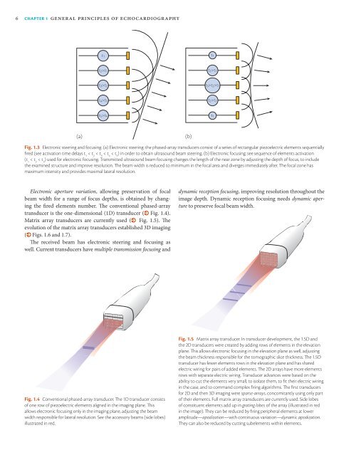
Fig. 1.3 Electronic steering and focusing. (a) Electronic steering: the phased-array transducers consist of a series of rectangular piezoelectric elements sequentially<br />
fired (see activation time delays t 1<br />
< t 2<br />
< t 3<br />
< t 4<br />
< t 5<br />
) in order to obtain ultrasound beam steering. (b) Electronic focusing: see sequence of elements activation<br />
(t 1<br />
< t 2<br />
< t 3<br />
) used for electronic focusing. Transmitted ultrasound beam focusing changes the length of the near zone by adjusting the depth of focus, to include<br />
the examined structure and improve resolution. The beam width is reduced to minimum in the focal area and diverges immediately after. The focal zone has<br />
maximum intensity and provides maximal lateral resolution.<br />
Electronic aperture variation, allowing preservation of focal<br />
beam width for a range of focus depths, is obtained by changing<br />
the fired elements number. The conventional phased-array<br />
transducer is the one-dimensional (1D) transducer (% Fig. 1.4).<br />
Matrix array transducers are currently used (% Fig. 1.5). The<br />
evolution of the matrix array transducers established 3D imaging<br />
(% Figs. 1.6 and 1.7).<br />
The received beam has electronic steering and focusing as<br />
well. Current transducers have multiple transmission focusing and<br />
dynamic reception focusing, improving resolution throughout the<br />
image depth. Dynamic reception focusing needs dynamic aperture<br />
to preserve focal beam width.<br />
Fig. 1.4 Conventional phased-array transducer. The 1D transducer consists<br />
of one row of piezoelectric elements aligned in the imaging plane. This<br />
allows electronic focusing only in the imaging plane, adjusting the beam<br />
width responsible for lateral resolution. See the accessory beams (side lobes)<br />
illustrated in red.<br />
Fig. 1.5 Matrix array transducer. In transducer development, the 1.5D and<br />
the 2D transducers were created by adding rows of elements in the elevation<br />
plane. This allows electronic focusing in the elevation plane as well, adjusting<br />
the beam thickness responsible for the tomographic slice thickness. The 1.5D<br />
transducer has fewer elements rows in the elevation plane and has shared<br />
electric wiring for pairs of added elements. The 2D arrays have more elements<br />
rows with separate electric wiring. Transducer advances were based on the<br />
ability to cut the elements very small, to isolate them, to fit their electric wiring<br />
in the case, and to command complex firing algorithms. The first transducers<br />
for 2D and then 3D imaging were sparse-arrays, concomitantly using only part<br />
of their elements. Full matrix array transducers are currently used. Side lobes<br />
of constituent elements add up in grating lobes of the array (illustrated in red<br />
in the image). They can be reduced by firing peripheral elements at lower<br />
amplitude—apodization—with continuous variation—dynamic apodization.<br />
They can also be reduced by cutting subelements within elements.