EACVI Echocardiography Textbook - sample
Discover the EACVI Textbook of Echocardiography 2nd edition
Discover the EACVI Textbook of Echocardiography 2nd edition

Create successful ePaper yourself
Turn your PDF publications into a flip-book with our unique Google optimized e-Paper software.
8<br />
Chapter 1 general principles of echocardiography<br />
result is a real-time image with higher spatial resolution due to a<br />
larger field of view, but even lower temporal resolution because of<br />
prolonged image formation time. To overcome this issue, a ‘full<br />
volume’ 3D data set is formed from stitching together subvolumes<br />
acquired over two to seven sequential cardiac cycles (usually<br />
four). This is a ‘near-real-time’ rather than a ‘real-time’ mode, but<br />
it allows higher line density with relatively high frame rate (still<br />
lower than the current 2D frame rate). ‘Full volume’ acquisition in<br />
one cardiac cycle is also available.<br />
Signal processing<br />
The transducer should receive all returning waves from an<br />
ultrasound pulse before generating a new pulse, to avoid range<br />
ambiguity artefact (confining waves returning late from one pulse<br />
in the same location with waves returning early from the next<br />
pulse). Consequently, the number of pulses per second—pulse<br />
repetition frequency (PRF)—depends on the maximum travelling<br />
time which depends on the imaging depth. For every scan line, the<br />
PRF determines the frame rate—the number of images generated<br />
per second and stored in memory. The higher the depth, the lower<br />
the PRF so the lower the frame rate. The higher the number of<br />
scan lines, the lower the frame rate. Higher imaging sector width<br />
needs more scan lines resulting in lower frame rate. The frame rate<br />
determines the temporal resolution.<br />
In current transducers, able to transmit and receive a range of<br />
frequencies, a different PRF corresponds to each frequency:<br />
◆ 5 MHz = >71.8 PRF<br />
◆ 4 MHz = >60.9 PRF<br />
◆ 3.3 MHz = >55.8 PRF.<br />
From the image stored in the memory an image display is created<br />
and presented. The number of images displayed per second<br />
defines the refresh rate which is smaller or equal to the frame rate.<br />
Both high frame rate and high refresh rate are needed for real-time<br />
imaging (rapid display of images during scanning, presenting the<br />
examined structures in motion).<br />
In older echocardiography machines, image display was performed<br />
in a cathode-ray tube and presented on a television screen<br />
or, later, on a computer monitor. The stored digital information<br />
was converted back to analogue voltages which induced a<br />
proportional strength electron beam generating a proportional<br />
brightness spot of light in the fluorescent tube. The spot moved<br />
across the tube creating the image display.<br />
In current echocardiography machines, both image display<br />
and presentation can be performed on a flat-panel consisting of a<br />
matrix of thousands of liquid crystal display (LCD) elements, acting<br />
as electrically activated light valves which can create grey-scale<br />
or colour images.<br />
Harmonic imaging<br />
Harmonic imaging substantially improves the image quality<br />
in 2D and M-mode. In non-harmonic imaging (fundamental<br />
imaging), the transducer receives only ultrasound signals from<br />
cardiac structures of the same frequency as that of the emitted<br />
ultrasound wave (fundamental frequency). In harmonic imaging,<br />
the transducer receives ultrasound signals from cardiac structures<br />
not only of fundamental frequency but also of higher frequency.<br />
The ultrasound wave produces compression and rarefaction of<br />
tissue particles (see % Fig. 1.1) and also oscillation of these particles<br />
both at fundamental frequency and at higher frequency and<br />
lower amplitude. These higher oscillation frequencies (harmonic<br />
frequencies) are exact multiples of the fundamental frequency. The<br />
harmonic amplitude is proportional with the square of the fundamental<br />
amplitude. Harmonic imaging exploits this non-linear<br />
response of tissue particles to the ultrasound beam.<br />
The generation of harmonic frequencies is a cumulative<br />
phenomenon, progressively augmenting with depth of tissue penetration.<br />
However, it results in a reduction of axial resolution of<br />
the ultrasound image.<br />
Harmonics generation increases with administration of contrast<br />
agents consisting of microbubbles with non-linear properties<br />
which suffer volume resonant oscillations with pressure variations<br />
(see % Chapter 8).<br />
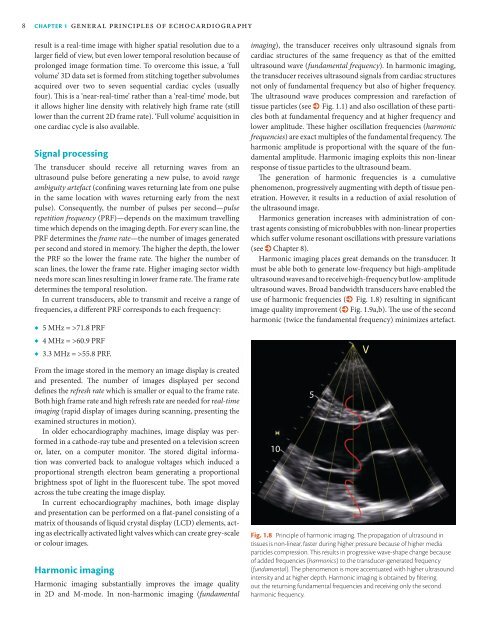
Harmonic imaging places great demands on the transducer. It<br />
must be able both to generate low-frequency but high-amplitude<br />
ultrasound waves and to receive high-frequency but low-amplitude<br />
ultrasound waves. Broad bandwidth transducers have enabled the<br />
use of harmonic frequencies (% Fig. 1.8) resulting in significant<br />
image quality improvement (% Fig. 1.9a,b). The use of the second<br />
harmonic (twice the fundamental frequency) minimizes artefact.<br />
10<br />
5<br />
Fig. 1.8 Principle of harmonic imaging. The propagation of ultrasound in<br />
tissues is non-linear, faster during higher pressure because of higher media<br />
particles compression. This results in progressive wave-shape change because<br />
of added frequencies (harmonics) to the transducer-generated frequency<br />
(fundamental). The phenomenon is more accentuated with higher ultrasound<br />
intensity and at higher depth. Harmonic imaging is obtained by filtering<br />
out the returning fundamental frequencies and receiving only the second<br />
harmonic frequency.<br />
V