Annals of Warsaw University of Life Sciences - SGGW
Annals of Warsaw University of Life Sciences - SGGW
Annals of Warsaw University of Life Sciences - SGGW

Create successful ePaper yourself
Turn your PDF publications into a flip-book with our unique Google optimized e-Paper software.
Contents:<br />
<strong>Annals</strong><br />
<strong>of</strong> <strong>Warsaw</strong><br />
<strong>University</strong><br />
<strong>of</strong> <strong>Life</strong><br />
<strong>Sciences</strong><br />
– <strong>SGGW</strong><br />
Forestry and Wood Technology No 71<br />
<strong>Warsaw</strong> 2010<br />
ANDRZEJ ANTCZAK “The study <strong>of</strong> thermal degradation <strong>of</strong> s<strong>of</strong>twood<br />
cellulose in the presence <strong>of</strong> antioxidants – FT-IR analysis” .................................................... 9<br />
ANTCZAK ANDRZEJ “The study <strong>of</strong> thermal degradation <strong>of</strong> s<strong>of</strong>twood cellulose<br />
in the presence <strong>of</strong> antioxidants – SEC analysis” ................................................................... 14<br />
BEER PIOTR, FUCZEK DOROTA, KOWALUK GRZEGORZ, ZBIE� MARCIN<br />
“Possibilities and limits <strong>of</strong> the finishing <strong>of</strong> the particleboards from fibrous chips” ............... 20<br />
BELCHINSKAYA L.I., SEDLIACIK JAN, VARIVODIN V.A., ANISIMOV �.�.<br />
“��������� ������������ ����������� ������� ����������,<br />
���������� ������������” .............................................................................................. 24
BIERNACKA JUSTYNA, SEDLIA�IKOVÁ MARIANA „The analysis <strong>of</strong><br />
roundwood and sawnwood production in selected European Union countries” .................... 28<br />
BIERNACKA JUSTYNA, SEDLIA�IKOVÁ MARIANA “Competitiveness analysis<br />
<strong>of</strong> wood industry sector in selected European Union countries” ........................................... 31<br />
BODNÁR FERDINAND, JAB�O�SKI MAREK “Stress concentration factors <strong>of</strong> an<br />
anisotropic elastic plate with an elliptical hole ...................................................................... 37<br />
BOMBIN A.M., MORDVINOV P.S. “Two special plants for drying <strong>of</strong> wood by<br />
superhigh frequency <strong>of</strong> electromagnetic energy” .................................................................. 42<br />
BORATY�SKI EMILIAN, JANKOWSKA AGNIESZKA,<br />
SZCZ�SNA MAGDALENA “Influence <strong>of</strong> the accelerated ageing red oak wood<br />
(Quercus rubra L.) on compressive strength along the fibers” .............................................. 47<br />
BORUSZEWSKI PIOTR, BORYSIUK PIOTR, DOBROWOLSKA EWA,<br />
MAMI�SKI MARIUSZ, NICEWICZ DANUTA „Interactions with water <strong>of</strong> novel<br />
wood-fiber material with lignins as binder” .......................................................................... 51<br />
BORYSIUK PIOTR, BORUSZEWSKI PIOTR, KRAJEWSKI KRZYSZTOF,<br />
JABLO�SKI MAREK, RUŽINSKÁ EVA „Shear strength <strong>of</strong> bonds in plywood<br />
made <strong>of</strong> veneers treated with pyrethroid and triazole based bio-preservatives” .................... 56<br />
BORYSIUK PIOTR, SZO�UCHA MARCIN, JASKÓ�OWSKI WALDEMAR,<br />
CZECHOWSKA JOANNA „Low-density particleboards with foamed<br />
polystyrene additive” ............................................................................................................ 62<br />
������� ������� “����������� ������-������������ �������<br />
��������� ������” .............................................................................................................. 67<br />
CHUCHALA D., MISZKIEL K., ORLOWSKI K.A. „Methods <strong>of</strong> determining<br />
cutting forces during woodcutting” ....................................................................................... 70<br />
CYRANKOWSKI MARIUSZ, BAJKOWSKI BOGUS�AW “The role <strong>of</strong> lighting in<br />
vision systems” ..................................................................................................................... 75<br />
CYRANKOWSKI MARIUSZ, WROTEK HUBERT “Advanced quality control<br />
methods for wood” ................................................................................................................ 79<br />
CZARNECKI RAFA�, DUKARSKA DOROTA “Estimating the possibilities <strong>of</strong><br />
applying Sida hermaphrodita Rusby to the production <strong>of</strong> low-density particleboards” ........ 83<br />
CZARNIAK PAWE�, WILKOWSKI JACEK, MAZUREK ANDRZEJ „Influence<br />
<strong>of</strong> tool wear and cutting force on machining quality during milling <strong>of</strong><br />
laminated particleboard ......................................................................................................... 87<br />
CZECHOWSKA JOANNA, BORYSIUK PIOTR, MAMI�SKI MARIUSZ „Selected<br />
properties <strong>of</strong> low-density pine and poplar-pine particleboards” ............................................ 92<br />
DANIHELOVÁ ANNA, �ULÍK MARTIN, RUŽINSKÁ EVA,<br />
JAB�O�SKI MAREK, ZBIE� MARCIN “The magnetic properties spruce wood<br />
and their influence on wood quality” .................................................................................... 97<br />
2
�������� �����, �������� ��������, ���������� ������<br />
“������������ ���������� ������������ ���������������������� �������<br />
���������” ........................................................................................................................ 101<br />
�������� �����, �������� ��������, ������� ������<br />
“�������������� �������� ����������� ���� �������� �������” ............................. 106<br />
DIETZ HANS, KRZOSEK S�AWOMIR “Entwicklungstendenzen bei<br />
Bandsägeführungen im Sägewerk” ..................................................................................... 110<br />
DOBROWOLSKA EWA, KOZAKIEWICZ PAWE� “Die Sägegatter in der deutschen<br />
Literatur des 18. Jh. Nach Sturm und Zedler” ..................................................................... 114<br />
DOLACIS J�NIS, ANTONS ANDIS, PAVLOVI�S GUN�RS, C�RULE DACE<br />
“Relationship between the anatomical structure elements and mechanical properties<br />
in the trunk transverse and longitudinal direction for wood <strong>of</strong> Norway spruce<br />
(Picea abies (L.) Karst.) growing in Latvia” ....................................................................... 126<br />
DOLNY STANIS�AW, ROGOZI�SKI TOMASZ „Preliminary research <strong>of</strong> the<br />
processes <strong>of</strong> filtering purification <strong>of</strong> the air polluted by dust arisen during tooling<br />
the particleboards” .............................................................................................................. 130<br />
DOLNY STANIS�AW, ROGOZI�SKI TOMASZ “Air pulse pressure in conditions<br />
<strong>of</strong> air cleaning from wood dusts by filtration” .................................................................... 134<br />
DOLNY STANIS�AW, ROGOZI�SKI TOMASZ “Influence <strong>of</strong> moisture content<br />
on the physical and aerodynamic properties <strong>of</strong> dusts from working <strong>of</strong> particleboards” ...... 138<br />
DRÁBEK JOSEF, SEDLIA�IKOVÁ MARIANA, BIERNACKA JUSTYNA<br />
“The suggesting approach to the measuring and evaluating <strong>of</strong> the efficiency <strong>of</strong><br />
Small and Medium Enterprises (SMEs) in the furniture industry” ...................................... 142<br />
DRO�D�EK MICHA� “Influence <strong>of</strong> isolation conditions on the degradation degree<br />
<strong>of</strong> scots pine wood (Pinus sylvestris L.)” ............................................................................ 147<br />
DUKARSKA DOROTA, ��CKA JANINA “Synthetic silica as a filler <strong>of</strong> phenolic<br />
resin in the manufacture <strong>of</strong> exterior plywood” .................................................................... 152<br />
DUKARSKA DOROTA, ��CKA JANINA, ZAJDLER MAGDALENA<br />
„The influence <strong>of</strong> adding <strong>of</strong> TiO2 and CaCO3 to phenolic resin upon the colour<br />
<strong>of</strong> glue line and properties <strong>of</strong> water-resistant plywood” ..................................................... 157<br />
DZIURKA DOROTA “Improved water resistance and adhesive performance <strong>of</strong> a<br />
commercial UF resin with small pMDI additions” ............................................................. 162<br />
DZIURKA DOROTA, ��CKA JANINA “Veneered lightweight particleboards for<br />
furniture industry” ............................................................................................................... 166<br />
FABISIAK EWA, CUNDERLIK IGOR, MOLI�SKI WALDEMAR<br />
“Ultrastructure and ultrasound wave propagation velocity in spruce (Picea abies L.)<br />
resonance wood” ................................................................................................................. 170<br />
FOJUTOWSKI ANDRZEJ, KROPACZ ALEKSANDRA, NOSKOWIAK ANDRZEJ<br />
“Resistance <strong>of</strong> thermomodified spruce and alder wood to moulds fungi” .......................... 177<br />
3
GÁBORÍK JOZEF, DUDAS JURAJ, KULÍK JOZEF “Selected properties <strong>of</strong> laminated<br />
wood <strong>of</strong> poplar” .................................................................................................................. 182<br />
GAFF MILAN, MACEK ŠTEFAN, ZEMIAR JÁN “Model analysis <strong>of</strong> laminar<br />
materials stressed by bending” ............................................................................................ 187<br />
������� ��������, �������� ������ “����������� �����������<br />
������������� ��������� � ��������� ���������� � ���� �������” ......................... 194<br />
GOZDECKI CEZARY, KOCISZEWSKI MAREK, WILCZY�SKI ARNOLD<br />
“Wood-polyethylene composite with industrial wood particles” ........................................ 199<br />
GOZDECKI CEZARY, KOCISZEWSKI MAREK, WILCZY�SKI ARNOLD,<br />
MIROWSKI JACEK „Effect <strong>of</strong> wood bark content on mechanical properties<br />
<strong>of</strong> wood-polyethylene composite” ...................................................................................... 203<br />
GROBELNY TOMASZ, KARDA� DOROTA, GÓRALSKI TOMASZ<br />
“Perforation <strong>of</strong> blade as a way to increase the stiffness <strong>of</strong> frame saw” ............................... 207<br />
GROBELNY TOMASZ, KARDA� DOROTA, JASI�SKI BARTOSZ<br />
“Influence <strong>of</strong> rake angle <strong>of</strong> scoring saw on cutting quality” ............................................... 211<br />
GRZE�KIEWICZ MAREK, K�DZIERSKI ANDRZEJ, SWACZYNA IRENA,<br />
POLICI�SKA-SERWA ANNA „Comparative studies <strong>of</strong> varying characteristics <strong>of</strong><br />
wood surfaces after exposure to natural climate and accelerated aging” ............................ 217<br />
GRZE�KOWIAK WOJCIECH �., BARTKOWIAK MONIKA “Flammability <strong>of</strong><br />
thermally modified wood originated from the industry – part I - mass losses” ................... 221<br />
GRZE�KOWIAK WOJCIECH �., BARTKOWIAK MONIKA<br />
“Flammability <strong>of</strong> thermally modified wood originated from the industry – part II -<br />
temperature distribution” .................................................................................................... 225<br />
GRZE�KOWIAK WOJCIECH �., WI�NIEWSKI TOMASZ<br />
“Fire safety <strong>of</strong> fireplaces – wood based products speed <strong>of</strong> charring” .................................. 229<br />
H’NG P.S., CHAI L.Y., CHIN K.L., MAMI�SKI M. “Oil palm wood (Elaeis<br />
guineensis Jacq.) as an underutilized resource <strong>of</strong> raw materials” ........................................ 235<br />
JAB�O�SKI MAREK, SEDLIA�IK JÁN, RUŽINSKÁ EVA<br />
“Less popular application <strong>of</strong> trees and bushes growing in Poland and Slovakia” ............... 240<br />
JANDA�KA JOZEF, KAPJOR ANDREJ, PAPU�ÍK ŠTEFAN,<br />
LENHARD RICHARD “Emission and power parameters <strong>of</strong> combined heat source on<br />
wood biomass combustion” ................................................................................................ 245<br />
JANDA�KA JOZEF, HUŽVÁR JOZEF, KAPJOR ANDREJ<br />
“Project <strong>of</strong> micro co-generation unit on wood pellets combustion” .................................... 250<br />
JANDA�KA JOZEF, HOLUB�ÍK MICHAL, NOSEK RADOVAN, PILÁT PETER<br />
“The effect <strong>of</strong> additives for production <strong>of</strong> wood pellets” .................................................... 255<br />
JANDA�KA JOZEF, PILÁT PETER, NOSEK RADOVAN, �AJA ALEXANDER<br />
“The influence <strong>of</strong> boiler regulation to emission parameters and heat power” ..................... 261<br />
4
JANDA�KA JOZEF, NOSEK RADOVAN, PAPU�ÍK ŠTEFAN,<br />
CHABADOVÁ JANA “The influence <strong>of</strong> fuel supply to emissions parameters and<br />
heat power <strong>of</strong> domestic boiler” ........................................................................................... 265<br />
JANKOWSKA AGNIESZKA, KOZAKIEWICZ PAWE�, SZCZ�SNA MAGDALENA<br />
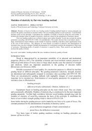
“Discoloration <strong>of</strong> bilinga (Nauclea diderrichii (De Wild. & Th.Dur.) Merr.) and iroko<br />
(Milicia excelsa (Welw.) C.C.Berg.) wood, caused by coatings and light aging” ............... 270<br />
JANKOWSKA AGNIESZKA “Comparative analysis <strong>of</strong> wood ageing methods” .............. 275<br />
JANKOWSKA AGNIESZKA, ST�PNIEWSKI SEBASTIAN “Research on colour<br />
change <strong>of</strong> thermal modified birch wood caused by UV and accelerated ageing ................. 280<br />
JASKÓ�OWSKI WALDEMAR, MAMI�SKI MARIUSZ “Emissions CO and CO2<br />
from particleboard filled with mineral wool in fire conditions” .......................................... 285<br />
JASKÓ�OWSKI WALDEMAR, BORYSIUK PIOTR “Emissions <strong>of</strong> CO and CO2<br />
from particleboard filled with polystyrene in fire conditions” ........................................... 291<br />
JASKÓ�OWSKI WALDEMAR, KOZAKIEWICZ PAWE�, SZWED MAREK<br />
“Thermogravimetric research on the influence <strong>of</strong> wood species on its thermal<br />
decomposition” ................................................................................................................... 296<br />
JASKÓ�OWSKI WALDEMAR, KOZAKIEWICZ PAWE�, POP�AWSKI MAREK<br />
“Study on the influence <strong>of</strong> thickness <strong>of</strong> dust layer to ignition temperature in selected<br />
types <strong>of</strong> exotic woods” ........................................................................................................ 300<br />
JASTRZ�B JOANNA ”Die Eigenschaften der OSB–Platten modifiziert mit<br />
thermoplastischen Kunstst<strong>of</strong>fen in der Abhängigkeit von der Presstemperatur” ................ 304<br />
JASTRZ�B JOANNA “Der Einfluss des Aktivators auf die Eigenschaften der<br />
OSB–Platten modifiziert mit thermoplastischen Kunstst<strong>of</strong>fen” ......................................... 309<br />
JASZCZUR ANNA, MODZELEWSKA IZABELA, KOKOSZKA AGNIESZKA,<br />
�O�NOWSKI PAWE� „Strength properties and biodegradation <strong>of</strong> paper products<br />
manufactured from broad-leaved bleached kraft pulp supplemented with starch and<br />
resin glue additives” ............................................................................................................ 314<br />
JAVOREK L., HRIC J. “The curved cutting edge wearing (back face) during<br />
greenwood turning “ ............................................................................................................ 319<br />
JAVOREK L., PAULINY D., HRIC J. “The influence <strong>of</strong> the tool design to<br />
cutting force “ ..................................................................................................................... 323<br />
JELONEK TOMASZ, TOMCZAK ARKADIUSZ “Biomechanics <strong>of</strong> Scots pine<br />
(Pinus sylvestris L.) trees coming from mature stands” ...................................................... 328<br />
JELONEK TOMASZ, PAZDROWSKI WITOLD, TOMCZAK ARKADIUSZ,<br />
JAKUBOWSKI MARCIN „Dynamics <strong>of</strong> heartwood formation in European larch<br />
(Larix decidua Mill.) in terms <strong>of</strong> age and variation in social tree position in the stand” ..... 336<br />
KARPOVI� ZBIGNEV, JASKÓ�OWSKI WALDEMAR,<br />
MA�IULAITIS ROMUALDAS, PRANIAUSKAS VLADAS “Studies on<br />
combustibility <strong>of</strong> treated wood with fire retardant and antiseptic solutions” .................... 342<br />
5
K�DZIERSKI ANDRZEJ, POLICI�SKA – SERWA ANNA<br />
“The effect <strong>of</strong> ageing in natural conditions on the basic properties <strong>of</strong> water-based<br />
paint coatings” .................................................................................................................... 347<br />
KHODOSOVA N.A., SEDLIACIK JAN, VARIVODIN V.A., ANISIMOV �.�.<br />
“������������ ��������, �������� �� ������� ������������� �� ������” ........... 351<br />
KOWALCZYK SYLWESTER “Application <strong>of</strong> acoustic<br />
signals in preventing <strong>of</strong> animal damages in farming and forest cultivations” ..................... 355<br />
KOPECKÝ ZDEN�K, ROUSEK MIROSLAV, VESELÝ P�EMYSL<br />
“The noise level <strong>of</strong> circular sawblades with the irregular tooth pitch” ................................ 360<br />
KOWALUK GRZEGORZ, BORUSZEWSKI PIOTR, BORYSIUK PIOTR, ZBIE�<br />
MARCIN „Thermal characteristic <strong>of</strong> the particleboards produced from fibrous chips” ..... 367<br />
KOWALUK GRZEGORZ, ZBIE� MARCIN, BEER PIOTR<br />
“The quality <strong>of</strong> milling <strong>of</strong> the particleboards produced from fibrous chips” ....................... 371<br />
KOZAKIEWICZ PAWE�, SZCZ�SNA MAGDALENA, TOMCZAK<br />
MA�GORZATA “Shrinkage and swell in pine wood coming from XIX-th century<br />
constructional wood” .......................................................................................................... 374<br />
KOZAKIEWICZ PAWE�, MATEJAK MIECZYS�AW „Kreissägen” ............................ 378<br />
KOZAKIEWICZ PAWE�, DOBROWOLSKA EWA „Die Sägegatter in der deutschen<br />
Literatur des 18. Jh. Nach Florin und Leupold” .................................................................. 383<br />
KRAJ�OVI�OVÁ MÁRIA “Holzspielzeuge damals und Heute in der Slowakei” ........... 390<br />
KRAJEWSKI ADAM , MAZUREK ANDRZEJ “Exotic species <strong>of</strong> wood borers in<br />
investigations <strong>of</strong> Wood Protection Division <strong>SGGW</strong> in <strong>Warsaw</strong> in years 1997 – 2009” ..... 395<br />
KRAJEWSKI ADAM “The species <strong>of</strong> wood construction in historic churches in<br />
Mazovia region - Part 2” ..................................................................................................... 400<br />
KRAUSS ANDRZEJ, SZYMA�SKI WALDEMAR, PINKOWSKI GRZEGORZ<br />
„The radial variability <strong>of</strong> the modulus <strong>of</strong> elasticity along the grain <strong>of</strong> Scots pine wood” ... 404<br />
KRUTUL DONATA, ZIELENKIEWICZ TOMASZ, RADOMSKI ANDRZEJ,<br />
ZAWADZKI JANUSZ, DRO�D�EK MICHA�, ANTCZAK ANDRZEJ<br />
„Influence <strong>of</strong> urban environment originated heavy metals pollution on the content<br />
<strong>of</strong> extractives, cellulose and lignin in the oak wood” .......................................................... 410<br />
KRYSTOFIAK TOMASZ, PROSZYK STANIS�AW, LIS BARBARA, JURGA ANNA<br />
“Effect <strong>of</strong> thermal aging on properties <strong>of</strong> HDF boards finished in lacquer analogue<br />
printing technology. Part I. Coatings resistance upon thermal factors” ............................... 417<br />
KRYSTOFIAK TOMASZ, LIS BARBARA, PROSZYK STANIS�AW, JURGA ANNA<br />
“Effect <strong>of</strong> thermal aging on properties <strong>of</strong> HDF boards finished in lacquer analogue<br />
printing technology. Part II. Coatings resistance upon mechanical factors” ....................... 421<br />
KRZOSEK S�AWOMIR “Qualität von polnischem festigkeitssortierten<br />
Kieferschnittholz aus verschiedenen Wuchsgebieten” ........................................................ 425<br />
6
KUROWSKA AGNIESZKA, KOZAKIEWICZ PAWE� “Density and shear strength<br />
as solid wood and glued laminated timber suitability criterion for window woodwork<br />
manufacturing” ................................................................................................................... 429<br />
KUROWSKA AGNIESZKA, KOZAKIEWICZ PAWE�, BORYSIUK PIOTR<br />
“An attempt at the use <strong>of</strong> laboratory density analyzer for determination <strong>of</strong> solid wood<br />
cross section density distribution” ....................................................................................... 435<br />
������� ��������, ������ ������� “���� ������� ��� ������������<br />
����� MDF �������� ������������� ������” .............................................................. 440<br />
������� ��������, ������ ������� “������� ������-������������<br />
������� ����� MDF � �������� ������ �� �������� ��������� � ��������<br />
������������” ................................................................................................................... 444<br />
LIS BARBARA, KRYSTOFIAK TOMASZ, PROSZYK STANIS�AW<br />
“Studies <strong>of</strong> the resistance upon some factors <strong>of</strong> UV acrylic lacquer coatings<br />
on MDF boards. Part I. Resistance <strong>of</strong> heat and cold liquid action “ ................................... 450<br />
LIS BARBARA, KRYSTOFIAK TOMASZ, PROSZYK STANIS�AW<br />
“Studies <strong>of</strong> the resistance upon some factors <strong>of</strong> UV acrylic lacquer coatings on<br />
MDF boards. Part II. Mechanical factors” .......................................................................... 454<br />
LIS BARBARA, KRYSTOFIAK TOMASZ, PROSZYK STANIS�AW, WO�NIAK<br />
AGNIESZKA „Influence <strong>of</strong> thermal aging <strong>of</strong> veneering boards finished PUR lacquers<br />
in HC technology upon coatings properties. Part III. Resistance to thermal and<br />
chemical factors” ................................................................................................................ 458<br />
LIS BARBARA, KRYSTOFIAK TOMASZ, PROSZYK STANIS�AW, WO�NIAK<br />
AGNIESZKA „Influence <strong>of</strong> thermal aging <strong>of</strong> veneering boards finished <strong>of</strong> PUR lacquers<br />
in HC technology upon coating properties. Part IV. Wettability and adherence” ............... 462<br />
MAKOWSKI ANDRZEJ “Strength analysis <strong>of</strong> layered wood composite” ........................ 467<br />
MAKOWSKI A., NOSKOWIAK A., PAJCHROWSKI G., SZUMI�SKI G.<br />
“Strength and modulus <strong>of</strong> elasticity in bending <strong>of</strong> pine structural timber with square<br />
and round cross-section” ..................................................................................................... 473<br />
MAKSIMOWSKI PAWE�, ZAWADZKI JANUSZ , RADOMSKI ANDRZEJ<br />
“Use <strong>of</strong> pinene as component <strong>of</strong> special paints” ................................................................. 479<br />
MA�KOWSKI PIOTR, RADOMSKI ANDRZEJ<br />
“Thermal and photolytic ageing <strong>of</strong> Winacet RA” .............................................................. 484<br />
MA�KOWSKI PIOTR, ZIELENKIEWICZ TOMASZ, BORUSZEWSKI PIOTR<br />
“Iron chloride solution penetration into oak wood” ............................................................ 490<br />
�������� �������, ����� �������<br />
“������ ��������� ���������� �������������� �� ������� �����������” ............. 495<br />
MATYAŠOVSKÝ JÁN, JURKOVI� PETER, DUCHOVI� PETER<br />
“Collagen modified hardener for melamine-formaldehyde adhesive for increasing<br />
water-resistance <strong>of</strong> plywood” .............................................................................................. 499<br />
7
MAZELA BART�OMIEJ, HOCHMA�SKA PATRYCJA, RATAJCZAK IZABELA,<br />
SZENTNER KINGA „Enhancing the fungal performance <strong>of</strong> wood coatings by<br />
pre-treatment with Na2O-SiO2 solution” ............................................................................. 504<br />
MIKO�AJCZAK EL�BIETA “Biomass as a source <strong>of</strong> renewable energy in Poland” ....... 509<br />
MIRSKI RADOS�AW, DERKOWSKI ADAM<br />
“Bending strength <strong>of</strong> OSB subjected to boiling test” .......................................................... 515<br />
Board <strong>of</strong> reviewers:<br />
Pr<strong>of</strong>. dr hab. Bogus�aw Bajkowski<br />
Pr<strong>of</strong>. dr hab. Piotr Beer<br />
Dr hab. Ewa Dobrowolska<br />
Pr<strong>of</strong>. dr hab. Jaros�aw Górski<br />
Pr<strong>of</strong>. dr hab. Adam Krajewski<br />
Pr<strong>of</strong>. dr hab. Krzyszt<strong>of</strong> Krajewski<br />
Pr<strong>of</strong>. dr hab. Donata Krutul<br />
Dr hab. S�awomir Krzosek<br />
Dr hab. Hanna Pachelska<br />
Pr<strong>of</strong>. dr hab. Andrzej Starecki<br />
Pr<strong>of</strong>. dr hab. Irena Swaczyna<br />
Pr<strong>of</strong>. dr hab. Wac�aw Szymanowski<br />
Dr hab. Piotr Witomski<br />
Dr hab. Janusz Zawadzki<br />
D<strong>of</strong>inansowano ze �rodków Ministra Nauki i Szkolnictwa Wy�szego<br />
Polska Akademia Nauk Komitet Technologii Drewna<br />
WARSAW UNIVERSITY<br />
OF LIFE SCIENCES PRESS<br />
e-mail: wydawnictwo@sggw.pl<br />
ISSN 1898-5912<br />
SERIES EDITOR<br />
Ewa Dobrowolska<br />
Marcin Zbie� PRINT: ZPW POZKAL
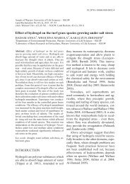
<strong>Annals</strong> <strong>of</strong> <strong>Warsaw</strong> <strong>University</strong> <strong>of</strong> <strong>Life</strong> <strong>Sciences</strong> – <strong>SGGW</strong><br />
Forestry and Wood Technology No 71, 2010: 9-13<br />
(Ann. WULS-<strong>SGGW</strong>, For and Wood Technol. 71, 2010)<br />
The study <strong>of</strong> thermal degradation <strong>of</strong> s<strong>of</strong>twood cellulose in the presence <strong>of</strong><br />
antioxidants – FT-IR analysis<br />
ANDRZEJ ANTCZAK<br />
Department <strong>of</strong> Wood Science and Wood Protection, <strong>Warsaw</strong> <strong>University</strong> <strong>of</strong> <strong>Life</strong> <strong>Sciences</strong> – <strong>SGGW</strong><br />
Abstract: The study <strong>of</strong> thermal degradation <strong>of</strong> s<strong>of</strong>twood cellulose in the presence <strong>of</strong> antioxidants – FT-IR<br />
analysis. The purpose <strong>of</strong> the study was examination antioxidant’s influence on cellulose crystallinity, which was<br />
submitted to thermal aging in 130°C. FT-IR spectroscopy was used to evaluate cellulose crystallinity. Generally,<br />
results obtained indicate that thermal aging <strong>of</strong> cellulose with/without antioxidant in oxygen conditions causes<br />
increase <strong>of</strong> cellulose crystallinity. Degradation <strong>of</strong> cellulose in the presence <strong>of</strong> THBP and EQ in 130ºC – air<br />
atmosphere probably proceeds mainly in amorphous regions. Addition <strong>of</strong> PG to cellulose matrix favors<br />
proceeding thermal cellulose degradation both in amorphous and crystalline regions. For aged cellulose in non<br />
extracted wood similar results were obtained. Thermal aging <strong>of</strong> cellulose with/without antioxidant in nitrogen<br />
atmosphere does not cause significant changes in cellulose crystallinity index.<br />
Keywords: thermal degradation, antioxidants, cellulose aging, FT-IR, crystallinity index<br />
INTRODUCTION<br />
Studies <strong>of</strong> cellulose degradation met with great interest in last years. This subject area<br />
is very important in many different industries (electrical, paper and textile) or in archives and<br />
libraries. To explain and understand cellulose degradation more precise and sensitive methods<br />
are required.<br />
Fourier transform infrared (FT-IR) spectroscopy is one <strong>of</strong> this technique. Using FT-IR<br />
method crystallinity <strong>of</strong> cellulose can be characterized. Nelson and O’Connor [1964 a, b]<br />
showed that bands at 1430 and 900 cm -1 are particularly sensitive to changes in crystallinity.<br />
Several authors have noted that cellulose undergoes changes in crystallinity upon chemical<br />
and physical treatments, for example heating. The increase in crystallinity may be explained<br />
as crystallization in quasicrystalline amorphous regions due to rearrangement or reorientation<br />
<strong>of</strong> cellulose molecules inside these regions. The second reason can be rate difference <strong>of</strong><br />
cellulose degradation in amorphous and crystalline regions. It is well known that the<br />
amorphous regions degrade more rapidly than crystalline ones.<br />
The purpose <strong>of</strong> the study was examination antioxidant’s influence on cellulose<br />
crystallinity, which was submitted to thermal aging in 130°C. FT-IR analysis application can<br />
give more detailed information about cellulose degradation.<br />
MATERIALS AND METHODS<br />
Research material<br />
- non extracted sawdust <strong>of</strong> pinewood (Pinus sylvestris L.) from sapwood zone<br />
- extracted sawdust <strong>of</strong> pinewood (Pinus sylvestris L.) from sapwood zone (without<br />
extractives) extracted by ethanol:chlor<strong>of</strong>orm (3:97)w mixture according to own method<br />
[Antczak et al. 2006]<br />
- cellulose – separated from above-mentioned extracted pinewood (Pinus sylvestris L.)<br />
by Kürschner-H<strong>of</strong>fer method [Krutul 2002]<br />
- above-mentioned pinewood cellulose with antioxidant – propyl gallate (PG), 2,4,5trihydroxyphenone<br />
(THBP) and ethoxyquin (EQ) which were coated on cellulose fibre<br />
by method with stirring [Antczak et al. 2007]. The method consisted in immersing a<br />
sample <strong>of</strong> cellulose in 0.2% antioxidant solution in methanol and then total<br />
evaporation <strong>of</strong> solvent under vacuum while stirring.<br />
9
Structural formulas <strong>of</strong> antioxidants (propyl gallate, etoxyquin and 2,4,5trihydroxybutyrophenone)<br />
are presented in Fig. 1.<br />
C<br />
H 3<br />
CH 2<br />
O<br />
CH 3<br />
N<br />
H<br />
HO<br />
HO<br />
etoxyquin<br />
CH 3<br />
CH 3<br />
OH<br />
O<br />
10<br />
O<br />
propyl gallate<br />
CH 2<br />
CH 2<br />
HO<br />
HO<br />
CH 3<br />
O<br />
OH<br />
CH 2<br />
CH 2<br />
2,4,5 - trihydroxybutyrophenone<br />
Fig. 1. Structural formulas <strong>of</strong> antioxidants (propyl gallate, etoxyquin and 2,4,5-trihydroxybutyrophenone)<br />
Accelerated ageing tests in air atmosphere<br />
At the beginning non extracted and extracted pinewood from sapwood zone, cellulose<br />
and cellulose with antioxidant (PG, THBP, EQ) were placed in desiccator with phosphorus<br />
pentaoxide (P2O5) (anhydrous conditions). In this vessel samples were submitted to<br />
accelerated ageing tests. Ageing tests were carried out in thermal chamber (KC 100/200,<br />
Elkon company) at 130ºC. Samples were collected after 15 days and were prepared to FT-IR<br />
analysis.<br />
Accelerated ageing tests in nitrogen atmosphere<br />
In this studies cellulose samples and samples <strong>of</strong> cellulose with antioxidant (PG, THBP,<br />
EQ) were used only. They were placed in desiccator with P2O5. Vacuum pump was used to<br />
remove the air to 6.6 mbar, then desiccator was filled with the nitrogen. The procedure was<br />
repeated three times. After that, samples in desiccator were submitted to accelerated ageing<br />
tests. Ageing tests were also carried out in thermal chamber (KC 100/200, Elkon company) at<br />
130ºC. Samples were also collected after 15 days and were prepared to FT-IR analysis.<br />
FT-IR analysis<br />
Preparation <strong>of</strong> cellulose samples to analysis<br />
Heat-treated (after 15 days) and untreated (control) cellulose samples were ground to<br />
homogeneous powder. Disintegrated samples were embedded in potassium bromide (KBr)<br />
pellets and were submitted to FT-IR analysis.<br />
CH 3
Conditions <strong>of</strong> FT-IR analysis and determination <strong>of</strong> cellulose crystallinity index<br />
FT-IR analysis <strong>of</strong> cellulose samples was carried out with using Spectrum 2000<br />
spectrophotometer (Perkin Elmer). FT-IR analysis conditions were as follows:<br />
- resolution: 4 cm -1<br />
- range <strong>of</strong> wavenumbers: 4000-400 cm -1<br />
- number <strong>of</strong> scans: 16<br />
Determination <strong>of</strong> cellulose crystallinity index was carried out from the ratio <strong>of</strong> the peaks areas<br />
absorbance at 1430 and 900 cm -1 (A1430/A900). This method gives the best results and was<br />
<strong>of</strong>ten used in many publications [Nelson & O’Connor 1964 a, 1964 b, O’Connor 1969,<br />
Klenkova 1976, Krutul 1986, Ali et al. 2001, Carrillo et al. 2004, Krutul et al. 2005, Krutul et<br />
al. 2009]. Baseline for maximum peak 1431.0 cm -1 was plotted from 1497.6 cm -1 to 1408.5<br />
cm -1 . Whereas baseline for maximum peak 897.3 cm -1 was plotted from 913.6 cm -1 do 847.9<br />
cm -1 . For each cellulose sample two measurements were done. Crystallinity index was used in<br />
order to better explanation <strong>of</strong> thermal cellulose degradation with/without antioxidant.<br />
RESULTS AND DISCUSSION<br />
In Table 1 and 2 cellulose crystallinity index (A1430 /A900) was presented from FT-IR<br />
analysis. Results showed in Table 1 indicate that thermal aging <strong>of</strong> cellulose in oxygen<br />
conditions causes increase <strong>of</strong> cellulose crystallinity. The highest increase was observed for<br />
thermally aged cellulose with THBP and EQ. Moreover thermal degradation <strong>of</strong> cellulose in<br />
extracted and non extracted wood also causes increase <strong>of</strong> crystallinity index, but to a lesser<br />
extent. In other hand PG addition to cellulose matrix does not cause significant changes in<br />
cellulose crystallinity.<br />
Table 1. Crystallinity index (A1430 /A900) <strong>of</strong> cellulose, cellulose with antioxidant (EQ, PG, THBP) and cellulose<br />
in extracted and non extracted wood aged in 130ºC in air atmosphere after 15 days<br />
Sample name A1430 /A900<br />
cellulose (control-unaged) 2.76<br />
cellulose (aged) 3.03<br />
cellulose with THBP (aged) 3.31<br />
cellulose with PG (aged) 2.79<br />
cellulose with EQ (aged) 3.28<br />
cellulose in non extracted wood (aged) 2.82<br />
cellulose in extracted wood (aged) 2.94<br />
The crystallinity index might be expected to increase, since the amorphous regions<br />
degrade more rapidly than the crystalline ones. So, it can be concluded that degradation<br />
process <strong>of</strong> cellulose in the presence <strong>of</strong> THBP and EQ in 130ºC – air atmosphere probably<br />
proceeds mainly in amorphous regions. Addition <strong>of</strong> other antioxidant (PG) to cellulose matrix<br />
favors proceeding thermal degradation <strong>of</strong> cellulose both in amorphous and crystalline regions.<br />
For cellulose in non extracted wood similar results were obtained. It is well known that propyl<br />
gallate has similar chemical structure to some wood extractives. So, in these two cases<br />
degradation <strong>of</strong> cellulose might proceed analogically.<br />
11
In relation to thermal aging <strong>of</strong> cellulose with/without antioxidant in nitrogen<br />
atmosphere (Table 2) it can be observed that inert gas conditions does not cause significant<br />
changes in cellulose crystallinity index.<br />
Table 2. Crystallinity index (A1430 /A900) <strong>of</strong> cellulose and cellulose with antioxidant (EQ, PG, THBP) aged in<br />
130ºC in nitrogen atmosphere after 15 days<br />
Sample name A1430 /A900<br />
cellulose (control-unaged) 2.76<br />
cellulose (aged) 2.80<br />
cellulose with THBP (aged) 2.78<br />
cellulose with PG (aged) 2.86<br />
cellulose with EQ (aged) 2.89<br />
CONCLUSIONS<br />
On the basis <strong>of</strong> the performed studies following conclusions can be drawn:<br />
1. Results obtained indicate that thermal aging <strong>of</strong> cellulose with/without antioxidant in<br />
oxygen conditions causes increase <strong>of</strong> cellulose crystallinity. Only for cellulose with PG<br />
and cellulose in non extracted wood changes <strong>of</strong> crystallinity are not significant.<br />
2. Degradation <strong>of</strong> cellulose in the presence <strong>of</strong> THBP and EQ in 130ºC – air atmosphere<br />
proceeds mainly in amorphous regions. Addition <strong>of</strong> PG to cellulose matrix favors<br />
proceeding thermal cellulose degradation both in amorphous and crystalline regions.<br />
For cellulose in non extracted wood similar results were obtained.<br />
3. Thermal aging <strong>of</strong> cellulose with/without antioxidant in nitrogen atmosphere does not<br />
cause significant changes in cellulose crystallinity index.<br />
REFERENCES<br />
1. M.L. NELSON, R.T. O’CONNOR, Relation <strong>of</strong> certain infrared bands to cellulose<br />
crystallinity and crystal lattice type. Part I. Spectra <strong>of</strong> lattice types I, II, III and<br />
amorphous cellulose, J. Appl. Polym. Sci. 8 (1964 a) 1311-1324.<br />
2. M.L. NELSON, R.T. O’CONNOR, Relation <strong>of</strong> certain infrared bands to cellulose<br />
crystallinity and crystal lattice type. Part II. A new infrared ratio for estimation <strong>of</strong><br />
crystallinity in cellulose I and II, J. Appl. Polym. Sci. 8 (1964 b) 1325-1341.<br />
3. ANTCZAK, A. RADOMSKI, J. ZAWADZKI, Benzene Substitution in Wood<br />
Analysis, <strong>Annals</strong> <strong>of</strong> <strong>Warsaw</strong> Agricultural <strong>University</strong>, Forestry and Wood Technology<br />
58 (2006) 15-19.<br />
4. D. KRUTUL, �wiczenia z chemii drewna oraz wybranych zagadnie� chemii<br />
organicznej, <strong>SGGW</strong>, Warszawa, 2002.<br />
5. ANTCZAK, A. RADOMSKI, J. ZAWADZKI, Determination <strong>of</strong> antioxidants in<br />
cellulose matrix, <strong>Annals</strong> <strong>of</strong> <strong>Warsaw</strong> <strong>University</strong> <strong>of</strong> <strong>Life</strong> <strong>Sciences</strong>, Forestry and Wood<br />
Technology 61 (2007) 15-19.<br />
6. R.T. O’CONNOR, Infrared absorption spectroscopy in the evaluation <strong>of</strong> cellulose and<br />
cellulose derivatives, Tappi 52 (1969) 566-572.<br />
7. N.I. KLENKOVA, Struktura i reakcjonnaja sposobnost’ cellulozy, Leningrad, 1976,<br />
pp. 31-52.<br />
12
8. D. KRUTUL, Charakterystyka celulozy w drewnie d�bowym wzd�u� osi i promienia<br />
pnia, Rozprawy Naukowe i Monografie, <strong>SGGW</strong>, Warszawa, 1986, p. 24.<br />
9. M. ALI, A.M. EMSLEY, H. HERMAN, R.J. HEYWOOD, Spectroscopic studies <strong>of</strong><br />
the ageing <strong>of</strong> cellulosic paper, Polymer 42 (2001) 2893-2900.<br />
10. F. CARRILLO, X. COLOM, J.J. SUNOL, J. SAURINA, Structural FTIR analysis and<br />
thermal characterization <strong>of</strong> lyocell and viscose-type fibres, European Polymer Journal<br />
40 (2004) 2229-2234.<br />
11. D. KRUTUL, J. ZAWADZKI, A. RADOMSKI, D. KAZEM-BEK, Application <strong>of</strong> IR<br />
spectrophotometry in comparative investigations <strong>of</strong> spruce wood (Picea excelsa L.)<br />
cellulose determined by laboratory methods, <strong>Annals</strong> <strong>of</strong> <strong>Warsaw</strong> Agricultural<br />
<strong>University</strong>, Forestry and Wood Technology 56 (2005) 377-382.<br />
12. D. KRUTUL, M. DRO�D�EK, T. ZIELENKIEWICZ, A. RADOMSKI, J.<br />
ZAWADZKI, A. ANTCZAK, Distribution and some properties <strong>of</strong> cellulose in the<br />
stem <strong>of</strong> oak wood (Quercus petraea Liebl.), <strong>Annals</strong> <strong>of</strong> <strong>Warsaw</strong> <strong>University</strong> <strong>of</strong> <strong>Life</strong><br />
<strong>Sciences</strong>, Forestry and Wood Technology 68 (2009) 436-443.<br />
Streszczenie: Badanie termicznej degradacji celulozy z drewna iglastego w obecno�ci<br />
przeciwutleniaczy – analiza FT-IR. Celem badania by�o sprawdzenie wp�ywu<br />
przeciwutleniacza na krystaliczno�� celulozy, która zosta�a poddana termicznemu starzeniu w<br />
130°C. Do okre�lenia krystaliczno�ci celulozy wykorzystano spektroskopi� FT-IR.<br />
Generalnie, otrzymane wyniki bada� wskazuj�, �e termiczne starzenie celulozy z/bez<br />
przeciwutleniacza w warunkach tlenowych powoduje wzrost krystaliczno�ci celulozy.<br />
Degradacja celulozy w obecno�ci THBP i EQ w 130°C – atmosfera powietrza,<br />
prawdopodobnie g�ównie przebiega w obszarach amorficznych. Dodatek PG do matrycy<br />
celulozy sprzyja przebiegowi termicznej degradacji celulozy zarówno w obszarach<br />
amorficznych jak i krystalicznych. Podobne wyniki uzyskano dla starzonej celulozy w<br />
drewnie nieekstrahowanym. Termiczne starzenie celulozy z/bez przeciwutleniacza w<br />
atmosferze azotu nie powoduje istotnych zmian w indeksie krystaliczno�ci celulozy.<br />
Acknowledgements: This scientific study is funded from the financial resources for science in years 2008-2010<br />
as a research project N N309 296834<br />
Corresponding author:<br />
Andrzej Antczak<br />
Department <strong>of</strong> Wood Science and Wood Protection,<br />
<strong>Warsaw</strong> <strong>University</strong> <strong>of</strong> <strong>Life</strong> <strong>Sciences</strong> (<strong>SGGW</strong>)<br />
ul. Nowoursynowska 159, 02-776 <strong>Warsaw</strong>, Poland<br />
e-mail: andrzej_antczak@sggw.pl
<strong>Annals</strong> <strong>of</strong> <strong>Warsaw</strong> <strong>University</strong> <strong>of</strong> <strong>Life</strong> <strong>Sciences</strong> – <strong>SGGW</strong><br />
Forestry and Wood Technology No 71, 2010: 14-19<br />
(Ann. WULS-<strong>SGGW</strong>, For and Wood Technol. 71, 2010)<br />
The study <strong>of</strong> thermal degradation <strong>of</strong> s<strong>of</strong>twood cellulose in the presence <strong>of</strong><br />
antioxidants – SEC analysis<br />
ANDRZEJ ANTCZAK<br />
Department <strong>of</strong> Wood Science and Wood Protection, <strong>Warsaw</strong> <strong>University</strong> <strong>of</strong> <strong>Life</strong> <strong>Sciences</strong> – <strong>SGGW</strong><br />
Abstract: The study <strong>of</strong> thermal degradation <strong>of</strong> s<strong>of</strong>twood cellulose in the presence <strong>of</strong> antioxidants – SEC<br />
analysis. The purpose <strong>of</strong> the study was examination antioxidants influence on degradation <strong>of</strong> cellulose during<br />
thermal ageing in 130°C. Size-exclusion chromatography was used to evaluate cellulose depolymerization. On<br />
the basis <strong>of</strong> these results, it was observed, that higher decrease <strong>of</strong> the polymerization degree <strong>of</strong> cellulose is in the<br />
air than in nitrogen atmosphere. Antioxidant addition – 0.2% (EQ, PG, THBP) to cellulose matrix considerably<br />
reduces the weight average polymerization degree <strong>of</strong> cellulose during thermal aging (130ºC) in air atmosphere.<br />
Also the presence <strong>of</strong> low molecular substances (extractives) accelerates thermo oxidative degradation <strong>of</strong><br />
cellulose. On the other hand, in nitrogen atmosphere, the presence <strong>of</strong> antioxidants does not cause significant<br />
changes in degradation <strong>of</strong> cellulose.<br />
Keywords: thermal degradation, antioxidants, cellulose aging, SEC<br />
INTRODUCTION<br />
Studies <strong>of</strong> cellulose degradation met with great interest in last years. This subject area<br />
is very important in many different industries (electrical, paper and textile) or in archives and<br />
libraries. It is generally known that cellulose degradation in natural conditions runs very slow.<br />
In order to model long-term changes in a shorter time scale, accelerated tests are used. In<br />
these tests samples are artificially aged by exposing them to elevated temperatures, specified<br />
humidity and atmosphere conditions.<br />
Size exclusion chromatography (SEC) is modern analytical technique which can be<br />
used to study cellulose degradation. This method gives information about the weight average<br />
molar mass (Mw), the number average molar mass (Mn) and also, what is the most important,<br />
the molar mass distribution (MMD) <strong>of</strong> polymeric sample. Moreover, the degree <strong>of</strong><br />
polymerization (DP) <strong>of</strong> cellulose can be obtained.<br />
The aim <strong>of</strong> the study was examination antioxidant’s influence on cellulose degradation<br />
during thermal ageing in 130°C. Natural antioxidants (extractives, lignin) and synthetic<br />
(especially phenolic compounds) are widely applied in a number <strong>of</strong> manufactured products to<br />
prevent oxidative degradation. However their effectiveness in thermal conditions still remains<br />
poorly understood.<br />
MATERIALS AND METHODS<br />
Research material<br />
- non extracted sawdust <strong>of</strong> pinewood (Pinus sylvestris L.) from sapwood zone<br />
- extracted sawdust <strong>of</strong> pinewood (Pinus sylvestris L.) from sapwood zone (without<br />
extractives) extracted by ethanol:chlor<strong>of</strong>orm (3:97)w mixture according to own method<br />
[Antczak et al. 2006]<br />
- cellulose – separated from above-mentioned extracted pinewood (Pinus sylvestris L.)<br />
by Kürschner-H<strong>of</strong>fer method [Krutul 2002]<br />
- above-mentioned pinewood cellulose with antioxidant – propyl gallate (PG), 2,4,5trihydroxyphenone<br />
(THBP) and ethoxyquin (EQ) which were coated on cellulose fibre<br />
by method with stirring [Antczak et al. 2007]. The method consisted in immersing a<br />
sample <strong>of</strong> cellulose in 0.2% antioxidant solution in methanol and then total<br />
evaporation <strong>of</strong> solvent under vacuum while stirring.<br />
14
Structural formulas <strong>of</strong> antioxidants (propyl gallate, etoxyquin and 2,4,5trihydroxybutyrophenone)<br />
are presented in Fig. 1.<br />
C<br />
H 3<br />
CH 2<br />
O<br />
CH 3<br />
N<br />
H<br />
HO<br />
HO<br />
etoxyquin<br />
CH 3<br />
CH 3<br />
OH<br />
O<br />
15<br />
O<br />
propyl gallate<br />
CH 2<br />
CH 2<br />
HO<br />
HO<br />
CH 3<br />
O<br />
OH<br />
CH 2<br />
CH 2<br />
2,4,5 - trihydroxybutyrophenone<br />
Fig. 1. Structural formulas <strong>of</strong> antioxidants (propyl gallate, etoxyquin and 2,4,5-trihydroxybutyrophenone)<br />
Accelerated ageing tests in air atmosphere<br />
At the beginning non extracted and extracted pinewood from sapwood zone, cellulose<br />
and cellulose with antioxidant (PG, THBP, EQ) were placed in desiccator with phosphorus<br />
pentaoxide (P2O5) (anhydrous conditions). In this vessel samples were submitted to<br />
accelerated ageing tests. Ageing tests were carried out in thermal chamber (KC 100/200,<br />
Elkon company) at 130ºC. Samples were collected every 3 days during 15 days and were<br />
prepared to SEC analysis in order to study cellulose degradation.<br />
Accelerated ageing tests in nitrogen atmosphere<br />
In this studies cellulose samples and samples <strong>of</strong> cellulose with antioxidant (PG, THBP,<br />
EQ) were used only. They were placed in desiccator with P2O5. Vacuum pump was used to<br />
remove the air to 6.6 mbar, then desiccator was filled with the nitrogen. The procedure was<br />
repeated three times. After that, samples in desiccator were submitted to accelerated ageing<br />
tests. Ageing tests were also carried out in thermal chamber (KC 100/200, Elkon company) at<br />
130ºC. Samples were also collected every 3 days during 15 days and were prepared to SEC<br />
analysis in order to examine cellulose degradation.<br />
SEC analysis<br />
Preparation <strong>of</strong> cellulose samples to analysis<br />
In order to study cellulose degradation in aged non extracted and extracted wood,<br />
cellulose was separated by Kürschner-H<strong>of</strong>fer method. All cellulose samples (50 mg <strong>of</strong> each)<br />
were treated with 50ml 0.01M sodium borohydride (NaBH4). After about 24h, cellulose was<br />
filtered through glass filter (G3) and washed with 5% acetic acid (20 ml) and next washed<br />
with water to neutral pH. After that, cellulose samples were treated with 1% sodium<br />
CH 3
hydroxide (NaOH) (20 ml) in nitrogen atmosphere for 1 hour using magnetic stirrer at room<br />
temperature (25ºC). Then cellulose was filtered and washed as earlier. This procedure<br />
facilitate complete dissolution <strong>of</strong> cellulose. Air-dry cellulose samples prepared in this way<br />
were submitted to activation and dissolution procedure. The procedure was carried out in<br />
vacuum Baker system SPE-12G and was as follows:<br />
- cellulose samples (15 mg) were placed in test-tubes (6 ml), poured distilled water (3 ml)<br />
and allowed to swell overnight;<br />
- next day the samples were carried to capillary tubes and subsequently washed with<br />
methanol, filtered and poured the next portion <strong>of</strong> methanol and left for 1 hour; this<br />
procedure with methanol was repeated twice;<br />
- after that, the samples were washed with N,N-dimethylacetamide (DMAc), filtered and<br />
poured the next portion <strong>of</strong> DMAc and left for 1 hour; this procedure was repeated and<br />
cellulose with DMAc was left untill the next day;<br />
- next day, the samples were filtered and poured 8% lithium chloride (LiCl) in DMAc (4<br />
ml);<br />
- cellulose dissolution in 8% LiCl/DMAc was realised using mixer (RM-2M, Elmi<br />
company);<br />
- after 1-2 days <strong>of</strong> dissolution, part <strong>of</strong> the sample (0.2 ml) was diluted to 0.5% LiCl<br />
concentration with pure DMAc (3 ml);<br />
- finally, prepared samples were submitted to SEC analysis.<br />
Conditions <strong>of</strong> SEC analysis<br />
SEC analysis <strong>of</strong> cellulose samples was carried out with using HPLC (High<br />
Performance Liquid Chromatography) system (LC-20AD, Shimadzu company), which was<br />
equipped with differential refractive detector (RID 10A, Shimadzu), pump (LC-20AD,<br />
Shimadzu) and oven (CTO-20A, Shimadzu). SEC analysis conditions were as follows:<br />
- 0.5% LiCl/DMAc as eluent<br />
- column – crosslinked polystyrene-divinylbenzene gel (PSS GRAM 10000, 10μ,<br />
8×300 mm) connected with guard column (PSS GRAM 10μ)<br />
- oven temperature: 80°C<br />
- flow rate: 2ml/min<br />
- injection volume: 200μl<br />
The chromatographic data were processed with PSS WinGPC scientific 2.74 s<strong>of</strong>tware.<br />
Twelve narrow molecular weight polystyrene standards (Polymer Laboratories) were used to<br />
calibrate the column. The polystyrene standards were prepared as mixed standards in four<br />
separate solutions in DMAc. The first standard solution contained polystyrene <strong>of</strong> the<br />
following peak molecular mass: 6 850 000, 565 000 and 11 300 Da, the second contained:<br />
3 950 000, 170 600 and 2 960 Da, the third contained: 3 150 000, 66 000 and 1 700 Da, and<br />
the fourth contained: 1 290 000, 28 500 and 580 Da. This polystyrene standards were used to<br />
calculate molecular mass <strong>of</strong> cellulose according to Mark-Houwink universal calibration:<br />
[�]=K×M � , where K and � are parameters, which depend on polymer type, solvent and<br />
temperature. For our chromatographic conditions, that parameters are the following: for<br />
polystyrene K=17.35×10 -3 cm 3 /g and �=0.642 [Timpa 1991] and for cellulose K=2.78×10 -3<br />
cm 3 /g and �=0.957 [Bikova & Treimanis 2002].<br />
RESULTS AND DISCUSSION<br />
Size exclusion chromatography was used to study thermal degradation <strong>of</strong> cellulose.<br />
This method enables determination <strong>of</strong> the weight average polymerization degree <strong>of</strong> cellulose.<br />
16
In Fig. 2, 3, 4 relationship between the weight average polymerization degree and aging time<br />
<strong>of</strong> cellulose aged in 130ºC in air and nitrogen atmosphere was presented. Results show, that in<br />
these aging conditions, pure cellulose is the most resistant to thermal degradation. Antioxidant<br />
addition – 0.2% (EQ, PG, THBP) to cellulose matrix considerably reduces the weight average<br />
polymerization degree <strong>of</strong> cellulose (Fig. 2). PG and THBP are the most aggressive<br />
antioxidants in oxygen conditions, especially at the beginning <strong>of</strong> aging process (during the<br />
first 6 days). EQ slower accelerates cellulose degradation. Only after 9 days considerable<br />
decrease <strong>of</strong> the weight average polymerization degree <strong>of</strong> cellulose with EQ is observed.<br />
(DPw)×10 -3<br />
2,7<br />
2,2<br />
1,7<br />
1,2<br />
Thermal aging in air atmosphere<br />
17<br />
R 2 = 0.9845<br />
R 2 = 0.9909<br />
cellulose<br />
R 2 cellulose with THBP<br />
= 0.9941<br />
R 2 = 0.9994<br />
0 3 6 9 12 15 18<br />
cellulose with EQ<br />
cellulose with PG<br />
aging time/days<br />
Fig. 2. Relationship between the weight average polymerization degree (DPw) and aging time <strong>of</strong> cellulose,<br />
cellulose with antioxidant (EQ, PG, THBP) aged in 130ºC in air atmosphere<br />
(DPw)×10 -3<br />
2,7<br />
2,2<br />
1,7<br />
1,2<br />
Thermal aging in air atmosphere<br />
R 2 = 0.9975<br />
R 2 = 0.9845<br />
R 2 = 0.9926<br />
0 3 6 9 12 15 18<br />
aging time/days<br />
cellulose<br />
cellulose in extracted<br />
wood<br />
cellulose in non<br />
extracted wood<br />
Fig. 3. Relationship between the weight average polymerization degree (DPw) and aging time <strong>of</strong> cellulose,<br />
cellulose in extracted and non extracted wood aged in 130ºC in air atmosphere<br />
Changes <strong>of</strong> the weight average polymerization degree <strong>of</strong> cellulose with PG and THBP<br />
are very interesting (Fig. 2). After 6 days <strong>of</strong> aging process in air atmosphere thermal<br />
degradation <strong>of</strong> cellulose with PG and THBP slows down. This phenomenon can be caused by<br />
production <strong>of</strong> more thermo stable oxidation products, which have stabilizing properties.
Another explanation can be fast consumption <strong>of</strong> antioxidant at the beginning <strong>of</strong> aging process.<br />
But rather the most probably reason <strong>of</strong> this phenomenon is the occurrence <strong>of</strong> amorphous<br />
regions, which are more susceptible to degradation. So, at the beginning <strong>of</strong> aging process,<br />
cellulose degradation mainly proceeds in the most accessible regions and decrease <strong>of</strong> the<br />
weight average polymerization degree <strong>of</strong> cellulose is the highest – for cellulose with PG and<br />
THBP. These assumptions are in agreement with the results <strong>of</strong> cellulose crystallinity index<br />
[Antczak 2010]. Results obtained for cellulose with EQ (Fig. 2) indicate that etoxyquin better<br />
inhibit cellulose degradation than other antioxidants, especially at the beginning <strong>of</strong> aging<br />
process. After 6 days cellulose degradation poceeds probably mainly in amorphous regions.<br />
Prove it the results <strong>of</strong> cellulose crystallinity index [Antczak 2010].<br />
In relation to thermal aging <strong>of</strong> extracted and non extracted wood the results presented<br />
in Fig. 3 indicate that cellulose in non extracted wood is the most degraded. Similarly as for<br />
cellulose with synthetic antioxidants, the presence <strong>of</strong> low molecular substances (extractives)<br />
accelerates thermal degradation <strong>of</strong> cellulose. Increase <strong>of</strong> cellulose degradation susceptibility<br />
in 130ºC in air atmosphere, probably can be caused by formation additional products from<br />
thermal decomposition or oxidation <strong>of</strong> synthetic antioxidants and extractives. These<br />
substances may have radical or hydroperoxide character. Such, very reactive products may<br />
contribute to effective degradation <strong>of</strong> cellulose chains [Kolar 1997].<br />
(DPw)×10 -3<br />
2,7<br />
2,2<br />
1,7<br />
1,2<br />
Thermal aging in nitrogen atmosphere<br />
18<br />
R 2 = 0.9919<br />
0 3 6 9 12 15 18<br />
aging time/days<br />
cellulose<br />
cellulose with EQ<br />
cellulose with PG<br />
cellulose with THBP<br />
Fig. 4. Relationship between the weight average polymerization degree (DPw) and aging time <strong>of</strong> cellulose,<br />
cellulose with antioxidant (EQ, PG, THBP) aged in 130ºC in nitrogen atmosphere<br />
Results <strong>of</strong> thermal aging <strong>of</strong> cellulose in nitrogen atmosphere in 130ºC (Fig. 4) indicate<br />
that antioxidant addition (EQ, PG, THBP) to cellulose matrix does not cause significant<br />
changes in degradation <strong>of</strong> cellulose. Probably, in this high temperature, synthetic antioxidants<br />
are less stable and rapidly undergo decomposition or evaporation, so their stabilizing activity<br />
is much worse.<br />
CONCLUSIONS<br />
On the basis <strong>of</strong> the performed studies following conclusions can be drawn:<br />
1. Antioxidant addition – 0.2% (EQ, PG, THBP) to cellulose matrix considerably reduces<br />
the weight average polymerization degree <strong>of</strong> cellulose during thermal aging (130ºC) in<br />
air atmosphere. Also the presence <strong>of</strong> low molecular substances (extractives) accelerates<br />
thermal degradation <strong>of</strong> cellulose.
2. Results obtained for cellulose with EQ indicate that etoxyquin in oxygen conditions<br />
better inhibit cellulose degradation than other antioxidants, especially at the beginning<br />
<strong>of</strong> aging process.<br />
3. Thermal aging <strong>of</strong> cellulose in nitrogen atmosphere characterizes lesser decrease <strong>of</strong> the<br />
weight average polymerization degree than in air atmosphere. Addition <strong>of</strong> antioxidant<br />
(EQ, PG, THBP) to cellulose matrix does not cause significant changes in degradation<br />
<strong>of</strong> cellulose.<br />
REFERENCES<br />
A. ANTCZAK, A. RADOMSKI, J. ZAWADZKI, Benzene Substitution in Wood<br />
Analysis, <strong>Annals</strong> <strong>of</strong> <strong>Warsaw</strong> Agricultural <strong>University</strong>, Forestry and Wood Technology<br />
58 (2006) 15-19.<br />
1. D. KRUTUL, �wiczenia z chemii drewna oraz wybranych zagadnie� chemii<br />
organicznej, <strong>SGGW</strong>, Warszawa, 2002.<br />
2. ANTCZAK, A. RADOMSKI, J. ZAWADZKI, Determination <strong>of</strong> antioxidants in<br />
cellulose matrix, <strong>Annals</strong> <strong>of</strong> <strong>Warsaw</strong> <strong>University</strong> <strong>of</strong> <strong>Life</strong> <strong>Sciences</strong>, Forestry and Wood<br />
Technology 61 (2007) 15-19.<br />
3. J.D. TIMPA, Application <strong>of</strong> universal calibration in gel permeation chromatography<br />
for molecular weight determinations <strong>of</strong> plant cell wall polymers; cotton fiber, Agrric.<br />
Food Chem. 39 (1991) 270-275.<br />
4. T. BIKOVA, A. TREIMANIS, Problems <strong>of</strong> the MMD analysis <strong>of</strong> cellulose by SEC<br />
using DMA/LiCl: A review, Carbohydrate Polymers 48 (2002) 23-28.<br />
5. ANTCZAK, The study <strong>of</strong> thermal degradation <strong>of</strong> s<strong>of</strong>twood cellulose in the presence<br />
<strong>of</strong> antioxidants – FT-IR analysis, <strong>Annals</strong> <strong>of</strong> <strong>Warsaw</strong> <strong>University</strong> <strong>of</strong> <strong>Life</strong> <strong>Sciences</strong>,<br />
Forestry and Wood Technology 71 (2010) – in press<br />
6. J. KOLAR, Mechanism <strong>of</strong> Autoxidative Degradation <strong>of</strong> Cellulose, Restaurator 18<br />
(1997) 163-176.<br />
Streszczenie: Badanie termicznej degradacji celulozy z drewna iglastego w obecno�ci<br />
przeciwutleniaczy – analiza SEC. Celem badania by�o sprawdzenie wp�ywu<br />
przeciwutleniacza na degradacj� celulozy podczas termicznego starzenia w 130°C. Do opisu<br />
zjawiska degradacji celulozy wykorzystano metod� chromatografii wykluczania<br />
przestrzennego (SEC). Na podstawie wyników bada� stwierdzono, �e w atmosferze powietrza<br />
dochodzi do wi�kszego spadku stopnia polimeryzacji celulozy ni� w atmosferze azotu.<br />
Dodatek przeciwutleniacza – 0,2% (EQ, PG, THBP) do matrycy celulozy znacznie obni�a<br />
�redni wagowy stopie� polimeryzacji celulozy podczas termicznego starzenia (130°C) w<br />
atmosferze powietrza. Równie� obecno�� ma�ocz�steczkowych substancji (ekstrakcyjnych)<br />
przyspiesza termo utleniaj�c� degradacj� celulozy. Z kolei w atmosferze azotu obecno��<br />
przeciwutleniaczy nie powoduje istotnych zmian w procesie degradacji celulozy.<br />
Acknowledgements: This scientific study is funded from the financial resources for science in years 2008-2010<br />
as a research project N N309 296834<br />
Corresponding author:<br />
Andrzej Antczak<br />
Department <strong>of</strong> Wood Science and Wood Protection,<br />
<strong>Warsaw</strong> <strong>University</strong> <strong>of</strong> <strong>Life</strong> <strong>Sciences</strong> (<strong>SGGW</strong>)<br />
ul. Nowoursynowska 159, 02-776 <strong>Warsaw</strong>, Poland<br />
e-mail: andrzej_antczak@sggw.pl<br />
19
<strong>Annals</strong> <strong>of</strong> <strong>Warsaw</strong> <strong>University</strong> <strong>of</strong> <strong>Life</strong> <strong>Sciences</strong> – <strong>SGGW</strong><br />
Forestry and Wood Technology No 71, 2010: 20-23<br />
(Ann. WULS-<strong>SGGW</strong>, For and Wood Technol. 71, 2010)<br />
Possibilities and limits <strong>of</strong> the finishing <strong>of</strong> the particleboards from fibrous<br />
chips<br />
PIOTR BEER 1 , DOROTA FUCZEK 2 , GRZEGORZ KOWALUK 3 , MARCIN ZBIE� 4<br />
1 Department <strong>of</strong> Construction and Technology <strong>of</strong> Final Wood Products, <strong>Warsaw</strong> <strong>University</strong> <strong>of</strong> <strong>Life</strong> Science,<br />
Nowoursynowska 159, 02-776 <strong>Warsaw</strong>, Poland<br />
2 Wood–Based Materials and Glues Department, Wood Technology Institute, Winiarska Str. 1, 60-654<br />
Pozna�, Poland<br />
3 Certification Centre <strong>of</strong> Wood Industry Products, Wood Technology Institute, Winiarska Str. 1, 60-654<br />
Pozna�, Poland<br />
4 Department <strong>of</strong> Mechanical Processing <strong>of</strong> Wood, <strong>Warsaw</strong> <strong>University</strong> <strong>of</strong> <strong>Life</strong> Science, Nowoursynowska 159, 02-<br />
776 <strong>Warsaw</strong>, Poland<br />
Abstract: Possibilities and limits <strong>of</strong> the finishing <strong>of</strong> the particleboards from fibrous chips. In the present paper<br />
the investigation results <strong>of</strong> the surface roughness <strong>of</strong> the particleboards produced from the fibrous chips from<br />
willow Salix Viminalis L. and robinia Robinia Pseudoacacia L. are described. There is no special limitations<br />
according to the finishing technology <strong>of</strong> the panels from fibrous chips. The surface <strong>of</strong> the panels produced from<br />
the fibrous chips are better than the surface <strong>of</strong> the panels made out from the industrial particles.<br />
Keywords: Particleboard, fibrous chip, surface, finishing, roughness.<br />
INTRODUCTION<br />
There are number <strong>of</strong> methods <strong>of</strong> finishing <strong>of</strong> the faces <strong>of</strong> the particleboards for furniture<br />
production. The most common industrial method is the overlapping by short-cycle laminating<br />
film, HPL or CPL. Another way is finishing with use <strong>of</strong> natural wood veneers. Because <strong>of</strong> the<br />
not attractive surface <strong>of</strong> raw particleboards, finishing <strong>of</strong> these panels with use transparent<br />
lacquers is practically unparalleled. The roughness <strong>of</strong> the finished surface can not be the most<br />
important when finishing by veneers with higher thicknesses. In case <strong>of</strong> thin overlapping<br />
materials, e.g. Touchwood, the finished surface should have the surface roughness well<br />
prepared, without appreciable cavities or irregularities. The “microchips” fractions used<br />
in particleboards’ face layers production, with high resination, help with achieving the proper,<br />
smooth surface. According to [Hiziroglu and Suzuki 2007] 1, also the density <strong>of</strong> the panels<br />
can influence the surface roughness. This conclusion is confirmed by [Nemli et al. 2005] 2.<br />
According to [Rolleri and R<strong>of</strong>fael 2009] 3 the particleboards with the outer layers made out<br />
from recycled particles had the roughest surfaces irrespective <strong>of</strong> the adhesive used, compare<br />
to the “fresh” microchips. There is no research conducted on the surface roughness in the light<br />
<strong>of</strong> the surface finishing method, for the particleboards produced from fibrous chips.<br />
The aim <strong>of</strong> this work was to investigate the surface roughness <strong>of</strong> the panels produced<br />
from fibrous chips from willow Salix Viminalis L. and robinia Robinia Pseudoacacia L.<br />
MATERIALS AND METHODS<br />
The panels from fibrous chips were prepared as it was mentioned by [Kowaluk et al.<br />
2010] 4. The three types <strong>of</strong> particles were used to panels production: robinia, willow and<br />
industrial particles. The panels were produced with two different densities: 660 and 600<br />
kg/m 3 . This give 6 different panel types: industrial particles (ip660 and ip600), robinia (r660<br />
and r600) and willow (w660 and w600). For investigations the sanded panels were taken<br />
before the finishing by laminate film. The measurements <strong>of</strong> the chosen parameters<br />
20
<strong>of</strong> the panels from fibrous chips surface roughness were conducted on MITUTOYO<br />
SURFTEST SJ-301 device, controlled by PC.<br />
RESULTS AND DISSCUSION<br />
The results <strong>of</strong> the measurement <strong>of</strong> the roughness <strong>of</strong> the panels produced from fibrous<br />
chips, as well as from industrial particles, are displayed on fig. 1 (parameters Ra and Rz) and<br />
fig. 2 (parameters Rp and Rv). As it is shown on fig. 1, the two highest values <strong>of</strong> Ra are for<br />
panels made out from industrial particles (ip660 and ip600). The lowest values <strong>of</strong> Ra are for<br />
panels made out from willow fibrous chips. The values <strong>of</strong> Rz have the similar tendency:<br />
highest for ip600 and the lowest for w660. It can be pointed that the roughness <strong>of</strong> the panels is<br />
getting better (the Ra and Rz) are smaller when the density <strong>of</strong> the panels is higher.<br />
Ra [�m]<br />
50<br />
40<br />
30<br />
20<br />
10<br />
0<br />
ip660 ip600 r660 r600 w660 w600<br />
Fig. 1. The values <strong>of</strong> Ra and Rz parameters for investigated panels.<br />
According to the fig. 2, where the values <strong>of</strong> the Rp and Rv for the investigated panels are<br />
displayed, the highest values <strong>of</strong> both mentioned parameters are for ip600 and the lowest for<br />
w660. The tendency <strong>of</strong> the better surface with the higher panel density is also clearly visible.<br />
Rp [�m]<br />
50<br />
45<br />
40<br />
35<br />
30<br />
25<br />
20<br />
15<br />
10<br />
5<br />
0<br />
Rp<br />
Rv<br />
ip660 ip600 r660 r600 w660 w600<br />
Fig. 1. The values <strong>of</strong> Rp and Rv parameters for investigated panels.<br />
21<br />
Ra<br />
Rz<br />
250<br />
200<br />
150<br />
100<br />
50<br />
0<br />
200<br />
180<br />
160<br />
140<br />
120<br />
100<br />
80<br />
60<br />
40<br />
20<br />
0<br />
Rz [�m]<br />
Rv [�m]
In the light <strong>of</strong> future finishing <strong>of</strong> the panels’ faces, more usable parameters are Rp and Rv.<br />
Those two parameters gives the information about the height <strong>of</strong> the peaks (Rp) and depth <strong>of</strong><br />
the valleys (Rv). If the Rp is low, the finishing material, i.e. laminate sheet will be better<br />
supported by face <strong>of</strong> the panel. The value <strong>of</strong> the Rv provides the characteristic <strong>of</strong> the surface<br />
in case <strong>of</strong> the future glues or lacquers/paints demand: the deeper valleys (higher Rv value)<br />
needs more above mentioned liquids to become fulfilled. It can be pointed, that the panels<br />
with the higher density have the better surface quality to finish with the most common<br />
method, i.e. laminating. It should be also mentioned, that, generally, the panels made out from<br />
the fibrous chips have the better surface quality, compare to the panels produced from the<br />
industrial particles.<br />
CONCLUSION<br />
On the basis <strong>of</strong> the above mentioned results, the following conclusions and remarks can<br />
be formulated:<br />
- the quality <strong>of</strong> the surface <strong>of</strong> the panels made out from the fibrous chips, measured<br />
by Ra, Rz, Rp and Rv is better than the surface <strong>of</strong> the panels produced from the<br />
industrial particles,<br />
- the quality <strong>of</strong> the panels is getting better with the panels’ density increase,<br />
- there is no special limitation in case <strong>of</strong> the finishing method <strong>of</strong> the panels produced<br />
from the fibrous chips, compare to the panels made out from the industrial particles.<br />
ACKNOWLEDGEMENTS<br />
This paper was financially supported by the Polish Ministry <strong>of</strong> Science and Higher Education<br />
within grant number N309 1068 33.<br />
REFERENCES<br />
1. S. HIZIROGLU, S. SUZUKI, Evaluation <strong>of</strong> surface roughness <strong>of</strong> commercially<br />
manufactured particleboard and medium density fiberboard in Japan, Journal<br />
<strong>of</strong> Materials Processing Technology 184 (2007) 436–440.<br />
2. G. NEMLI, I. OZTURK, I. AYDIN, Some <strong>of</strong> the parameters influencing surface<br />
roughness <strong>of</strong> particleboard, Building and Environment 40 (2005) 1337–1340.<br />
3. ROLLERI, E. ROFFAEL, Surface roughness <strong>of</strong> uncoated particleboards and its<br />
relation with the raw material, adhesive and climatic conditions, Eur. J. Wood Prod.<br />
DOI 10.1007/s00107-009-0363-8 (2009).<br />
4. G. KOWALUK, M. ZBIE�, P. BEER, The quality <strong>of</strong> milling <strong>of</strong> the particleboards<br />
produced from fibrous chips, Ann. WULS-<strong>SGGW</strong>, For and Wood Technol. 71, 2010.<br />
22
Streszczenie: Mo�liwo�ci oraz ograniczenia wyka�czania p�yt wiórowych z wiórów<br />
w�óknistych. W niniejszym artykule opisano wyniki pomiarów chropowato�ci powierzchni<br />
p�yt wiórowych z wiórów w�óknistych z wierzby Salix Viminalis L. oraz robinii Robinia<br />
Pseudoacacia L. Badania nie wykaza�y szczególnych ogranicze� co do technologii<br />
wyka�czania powierzchni badanych p�yt, w porównaniu do przemys�owych p�yt wiórowych.<br />
Powierzchnia p�yt z wiórów w�óknistych charakteryzowa�a si� wy�sz� jako�ci� w porównaniu<br />
do powierzchni p�yt z wiórów przemys�owych.<br />
Corresponding author:<br />
Certification Centre <strong>of</strong> Wood Industry Products, Wood Technology Institute, Winiarska Str. 1,<br />
60-654 Pozna�, Poland<br />
E-mail address: g_kowaluk@itd.poznan.pl (Grzegorz Kowaluk)
<strong>Annals</strong> <strong>of</strong> <strong>Warsaw</strong> <strong>University</strong> <strong>of</strong> <strong>Life</strong> <strong>Sciences</strong> – <strong>SGGW</strong><br />
Forestry and Wood Technology No 71, 2010: 24-27<br />
(Ann. WULS-<strong>SGGW</strong>, For and Wood Technol. 71, 2010)<br />
��������� ������������ ����������� ������� ����������,<br />
���������� ������������<br />
L.I. BELCHINSKAYA, JAN SEDLIACIK*, V.A. VARIVODIN, �.�. ANISIMOV<br />
Faculty <strong>of</strong> wood processing technology <strong>of</strong> Voronezh State Academy <strong>of</strong> forestry Engineering<br />
*���������� ����������� �����������, ��������, �. ������<br />
Abstract: ����������� ������� ����������� ��������� ������������ ������� ���������� �����- ��<br />
���������� ��������� ���� ��� ������������ ��������� ��������� ��������. � ��������<br />
������������ �������������� ��������� ��������������� ��������, ������������<br />
������������������� ���������. ��� �������� 2 % ��������� � ������� ���������� ���������<br />
������������� �� ������ ��������� � 2,2 ����, ��� ������������ ��������� ������������� ����������<br />
� ����������������, ����� ���������� � ���������� ����� � �����.<br />
Keywords: ������������, ���������� ��������� ����, �����������, ��������������� ��������,<br />
���������, ������� ����������, ������<br />
INTRODUCTION<br />
������� ������������ ������� � ������������� ������������� ���������� �<br />
����� ���������� �������� ������� ��������� ��� ���������� �������� ���������.<br />
� ������������� ���������� � ����� ���������� ����������� ������� ����������.<br />
���������� ������������ ������������� � ������� �������������� ���������<br />
���������� 0,1 ��/� 3 . ����������� ��������� ������� � ��������� ���������,<br />
������������ ���������, �������� � �������������� ������������������������<br />
���� � ����� �� �� ������. ����������� ������������������������ �������<br />
���������� �������� ������� ���������� �������������, ���������� ��������<br />
���������� � ���������� ����������� � ��������������� �������������� �����.<br />
������������ �������� ������� ������������, ����������� ������������ ��<br />
��������� �������� ����, ���� � ������� ����������� �����, ������� ������� [1, 2].<br />
�������� ����������� ����������, ���������� �������� ���������� ������� �������<br />
� ������� �������� ���� �������������� ���������, �������� ����������, ����������<br />
� ����������������� ��������. ������������ �������� ���������� �� ���������<br />
������� �� ������ ������������������������ ��� ��������������������� ����<br />
(���������, ����, �������, �������� �������� � ��). ��� ������������ ����������<br />
������������� ���������� ������������� � ����� ����������, ��� ��� � �������<br />
������� ��������� ��� ���������� ������� �� �������� ��������. � ������ �����������<br />
������� �������� ������� ������������� ��� �������� ��������� �������������� �<br />
������� ���������� �� ������ ������������������������ �����.<br />
MATERIALS AND METHODS<br />
� ������ ������ � �������� ������������ ������������ ��������: ������ –<br />
������������� � ������� ��������� ���������� (�) � �������������� (�) – ��������<br />
������� � ������������� ����������� �������.<br />
��� ������������� ������� ������������� ��������� ����������������<br />
��������������� ��������� ��������� � ���������� ��������� ���� � ���������<br />
24
��������� 0,011 �� � ����� 48 ����� ������� ���������� ������������ ��� 453 � [3].<br />
������������ �������������, ����������� �� ������� ����������,<br />
���������� ���������������� ������� [3], ��������� ������������� �� ������ –<br />
�������� �������.<br />
�������� ���������� �� ������������ ��-4.<br />
RESULTS AND DISCUTION<br />
����������� ������� ���������� ��������� � ���� �������� �� ������������<br />
����������� ������������� �� ������� ����������. ���������� �������� � ���������<br />
���� ����������� � �������� 1 - 3 % �� ����� ����. ���������� ������ ������������ �<br />
������� 1.<br />
������� 1. ������� ���������� ��������� �������� �� ������� �������������, ��/� 3<br />
�������<br />
���������� ����������� � ������� ����������, %<br />
1 2 3<br />
�������������� 0,138 0,134 0,133<br />
������������� 0,129 0,124 0,122<br />
����������� ���������� ��������� �������� ���������� 2 %.<br />
��������������� �������������� ����� (��������, ��, ����� �������������) �<br />
����������� 2 % ����������� ����������� �� �������� (����. 2).<br />
������� 2. ������-���������� �������� ������������ ����� � ����� � ������������<br />
����� �����<br />
�������� ����<br />
������ �������,<br />
%<br />
��������, �<br />
25<br />
�����<br />
�������������<br />
��� 20 � �<br />
1<br />
65,<br />
5<br />
55 �� ����� 10<br />
��-�<br />
7,85<br />
2<br />
67,<br />
5<br />
55,<br />
5<br />
�����<br />
����������<br />
1 – � ��������� ���������� �����, �� ���������� ��������-�����������;<br />
2 – � ����������� ���������� ����� � ������������<br />
���������� ��������� ������������� �� ������� ���������� � ������ ��<br />
������ ������������������������ ����� ��� �������� ��������� � ��������������<br />
������������ ���������. ��� ����������� ��������� ������������� �� ������� ����<br />
������������ ���������������� �����, � ��� ������������ ������� ������������� ��<br />
������ – ��������. ������ ������������ � ������� 3.<br />
������� 3. ������� ������������� �� ������� ���������� � ����������� �� ��������������������<br />
�������� ��������� � ���� ��������������� ���������<br />
���<br />
����������<br />
��������<br />
������� ������������� �� ������� ����, ��/� 3<br />
���������<br />
��������<br />
�/� ��������<br />
��������,<br />
������������ �<br />
���<br />
��<br />
��������,<br />
������������<br />
�/� � � ���<br />
� � � � � � � �<br />
0,141 0,134 0,124 0,099 0,085 0,084 0,105 0,075 0,081<br />
����������: �/� – ����������������� ��������; ��� – ��������, ������������ �<br />
���������� ��������� ����.<br />
��� ���������� � ���� ��������� ��������� ������� �������������<br />
��������� �� 5 – 12 %. �������������� � ������� ������� ���������� �� �����������<br />
������� ��������������, ��������� ��������� ������������� ����������� �� 31 %, �<br />
��� �������� ������������������ ��������������� – �� 26 %. ��������� ��������� �
���������� ��������� ���� ����� ������ �� �������� ������� ������������� ��<br />
������� ���������� � ���������������� (�� 38 %) � ����� �� ���������<br />
������������� �� ������� ���������� � ��������������� (�� 15%). ����������<br />
������������� �������� �������� ������� ����������, � ������� �������� 2 %<br />
���������������� �����������, ������������� ��������������� �����������<br />
��������� (� ���������� ��������� ���� � �����������). ��������� �������������<br />
����������� �� 44% ��� ���������� ���������������, �������� ��������������<br />
������� ������� �� 35 %.<br />
���������� ������� ���������� ������������ ��� ������������ ������ �<br />
���������� ������� �� ������������� �� ��������� ������������� (����. 4).<br />
������� 4. – ��������� ������������� �� ������ � ����������� �� �������������������� ��������<br />
��������� � ���� ��������������� ���������<br />
���<br />
����������<br />
��������<br />
������� ������������� �� ������, ��/� 3<br />
���������<br />
��������<br />
�/� ��������<br />
26<br />
��������,<br />
������������ �<br />
���<br />
��������,<br />
������������<br />
�/� � � ���<br />
� � � � � � � �<br />
0,124 0,120 0,112 0,087 0,076 0,072 0,091 0,056 0,073<br />
����������: �/� – ����������������� ��������; ��� – ��������, ������������ �<br />
���������� ��������� ����.<br />
��� �������� ��������� ������������ ��������� ������������� �� ������<br />
��������� �������������: � – �� 3 %, � – �� 10 %. �������������� ��������������<br />
�������� ������ �������� ��������� ������������� �� 38 %, � ��� ����������<br />
��������������� – �� 28 %. ��������� � ��� ���� ����������� �������� �����<br />
������������ �������� ����������� �� ������ ���������������, ��� ��� ���������<br />
������������� ����������� �� 40 %, � ��� ������������� ������������������<br />
����������� ���������� ������������� ��������� ������ �� 20 %.<br />
��� ����������� ��������� ������ ����������, �� ������� ���������� �<br />
���������������� ��������� ������������� ����������� �� 53 %, � ��������������� –<br />
35 %.<br />
CONCLUSION<br />
����������, ��� ������������� ������������� ��������� ������� �� ����<br />
��������������� ���������. �� ��������� ���������� ������ ��������� ��������<br />
������������� ������� ������� �������������. ������������ ��������������<br />
����������� ��� ��������������, � ����������� ����������� ���������� ���� – ��<br />
��������������. �������� ���������������, ������������� ���������� � ��� �<br />
����������, �������� � �������� ������� ������������� �� ������� ���������� ��<br />
40 %, � ��� �������� � ����� �������������� – �� 35 %. �� ������, ��������� ��<br />
������ � ����������� �������������� ������������ (�/� + ���) ���������<br />
��������������� � ��������������, ������� ������������� ��������� �� 53 % � 35%<br />
��������������.<br />
LITERATURE<br />
1. �����, ��.�. ������������ / ��. �. ����� – �.: ���. ������-����. ���.<br />
���������� ����������. 1957. – 608 �.
2. �������� �������, ���������, ���������������� ���������, ������� �<br />
��������� ��������, ������������� ��� ��������. �� 1.1.029-98.- �.:<br />
������������������ ������, 1995. – 17 �.<br />
3. �����������, �. �. ��������� ������������� �� ����������� ������������<br />
���������, ������������ ���������� ��������� ����� / ����������� �. �.,<br />
�������� �.�., �������� �.�. // ����������� ����������� � ������<br />
����������. – 2009. – �.45. �2. – �.218-221.<br />
4. Khodosova, N.A. Formaldehyde adsorption from a gas phase on thermomodification<br />
zeolite / Khodosova N.A., L.I. Belchinskaya // Achievements and Perspectives <strong>of</strong><br />
Modern Chemistry : Materials <strong>of</strong> II nd International Conference <strong>of</strong> the Chemical<br />
Society <strong>of</strong> the Republic Moldova, October 1-3, 2007 / Institute <strong>of</strong> Chemistry. –<br />
Chisinau, 2007. – P.37<br />
5. ��������, �.�. ����������� ����������� �� ������������������ ����<br />
������������� ��������������������� ������� � ��������������<br />
�������������: ��������-������. / �.�. �������� �. �. ��������, �.�.<br />
��������. – �.: ��������������, 1987. – �. 16-19. – (����� � ������; ���.<br />
12).<br />
Streszczenie: Uzyskanie skutecznej kompozycji klej�cej wype�niacza zawieraj�cego<br />
formaldehyd Stosowane jako wype�niacze glinokrzemian o ró�nej strukturze<br />
krystalograficznej. Wraz z wprowadzeniem 2% sorbentów w kleju sk�ad emisji formaldehydu<br />
ze sklejki zmniejszy� si� o 2,2 razy, a tym samym ogólna poprawa sytuacji ekologicznej w<br />
przemy�le, pomieszczeniach mieszkalnych i �rodowisku.
<strong>Annals</strong> <strong>of</strong> <strong>Warsaw</strong> <strong>University</strong> <strong>of</strong> <strong>Life</strong> <strong>Sciences</strong> – <strong>SGGW</strong><br />
Forestry and Wood Technology No 71, 2010: 28-30<br />
(Ann. WULS-<strong>SGGW</strong>, For and Wood Technol. 71, 2010)<br />
The analysis <strong>of</strong> roundwood and sawnwood production in selected European<br />
Union countries<br />
JUSTYNA BIERNACKA 1) , MARIANA SEDLIA�IKOVÁ 2)<br />
1) Department <strong>of</strong> Technology, Organisation and Management in Wood Industry,<br />
Faculty <strong>of</strong> Wood Technology, <strong>Warsaw</strong> <strong>University</strong> <strong>of</strong> <strong>Life</strong> <strong>Sciences</strong> (<strong>SGGW</strong>)<br />
2) Department <strong>of</strong> Business Economics,<br />
Faculty <strong>of</strong> Wood Science and Technology, Technical <strong>University</strong> in Zvolen<br />
Abstract: The analysis <strong>of</strong> roundwood and sawnwood production in selected European Union countries. In this<br />
paper production, export and import <strong>of</strong> roundwood and sawnwood <strong>of</strong> selected European Union countries. were<br />
analysed. This values analysis can provide many useful data for further, more detailed analysis, primarily in the<br />
competitiveness analysis <strong>of</strong> individual wood industry enterprise, but also the domestic wood industry sector<br />
competitiveness compared to other countries.<br />
Keywords: roundwood, sawnwood, production analysis, competitiveness.<br />
INTRODUCTION<br />
The roundwood and sawnwood production volume analysis is very important for wood<br />
industry companies. It can provide many useful information for the company management,<br />
but the analysis may provide many data to other entities, namely the statistical <strong>of</strong>fices. This<br />
data can be used in predicting future trends and facilitate taking appropriate strategic<br />
decisions.<br />
RESULTS<br />
In this paper the analysis <strong>of</strong> roundwood and sawnwood production and some values <strong>of</strong><br />
export and import in three European countries: Czech Republic, Poland and Slovakia were<br />
analysed. In the calculation the Eurostat and OECD data from 2004 to 2008 were used. The<br />
results were shown in table 1.<br />
Table 1. Total roundwood and sawnwood annual production changes in selected European Union countries<br />
Country Production<br />
2004<br />
Year (2004=100%)<br />
2005 2006 2007 2008<br />
Czech Republic<br />
roundwood<br />
sawnwood<br />
100,00%<br />
100,00%<br />
-0,58%<br />
1,60%<br />
13,31%<br />
28,93%<br />
18,63%<br />
38,43%<br />
3,76%<br />
17,66%<br />
Poland<br />
roundwood<br />
sawnwood<br />
100,00%<br />
100,00%<br />
-2,41%<br />
-10,23%<br />
-1,07%<br />
-3,63%<br />
9,78%<br />
18,01%<br />
4,70%<br />
1,15%<br />
Slovakia<br />
roundwood<br />
sawnwood<br />
100,00%<br />
100,00%<br />
28,48%<br />
42,68%<br />
8,69%<br />
32,83%<br />
12,31%<br />
51,39%<br />
28,02%<br />
54,71%<br />
Source: Authors’ own calculation based on Eurostat data<br />
Table 1 data analysis shows that in year 2005, compared to the 2004 a roundwood<br />
production in Poland and the Czech Republic has decreased (by 2,41% and 0,58%). This<br />
decreases however, can be regarded as negligible, because previous years data shows that<br />
both countries have significantly increased the roundwood production after their accession to<br />
the European Union (in the Czech Republic the increase <strong>of</strong> roundwood production in 2004<br />
28
compared to previous year reached over 8%, while in Poland over 25%). Only the Slovak<br />
Republic in 2005 noted the roundwood production increase, which compared to the year <strong>of</strong><br />
country's accession to the European Union reached approximately 30%. The data can indicate<br />
a positive evaluation <strong>of</strong> wood products market by wood-sector companies and their<br />
assumption <strong>of</strong> increasing the sales market as a result <strong>of</strong> opening European Union markets<br />
borders for central Europe countries.<br />
Figure 1 shows the graphic presentation <strong>of</strong> changes in the roundwood and sawnwood<br />
production in the three European Union countries. Figure 1 analysis shows that in recent years<br />
<strong>of</strong> analysed period the 2005 year’ increases <strong>of</strong> roundwood production (left scale) and<br />
sawnwood production (right scale) are gradually slowing down. The reason for this is<br />
continuous economic downturn in European and in global market. Reduction <strong>of</strong> sawnwood<br />
production can be seen especially in Poland and the Czech Republic. In the year 2008<br />
compared to the previous year the sawnwood production in these countries decreased by<br />
about 15%. Since 2006 only the Slovak Republic noted an upward trend <strong>of</strong> sawnwood<br />
production (in 2008 over the previous year production growth was just over 2%).<br />
35,00%<br />
30,00%<br />
25,00%<br />
20,00%<br />
15,00%<br />
10,00%<br />
5,00%<br />
0,00%<br />
-5,00%<br />
-10,00%<br />
2005<br />
2006<br />
29<br />
2007<br />
2008<br />
Czech Republic - roundwood production<br />
Poland - roundwood production<br />
Slovakia - roundwood production<br />
Czech Republic - sawnwood production<br />
Poland - sawnwood production<br />
Slovakia - sawnwood production<br />
65,00%<br />
55,00%<br />
45,00%<br />
35,00%<br />
25,00%<br />
15,00%<br />
5,00%<br />
-5,00%<br />
-15,00%<br />
Figure 1. Total roundwood and sawnwood annual production changes in Czech Republic, Poland and Slovakia<br />
(2004=100%)<br />
CONCLUSIONS<br />
The analysis showed, that in the initial years after Czech, Polish and Slovak accession to<br />
the European Union all roundwood and sawnwood production values in all mentioned<br />
countries had an upward trend. In comparison to the values <strong>of</strong> 2004 particularly positive<br />
results <strong>of</strong> changes in the roundwood production can be observed in Slovakia – throughout<br />
analysed period the country noted only positive values (from 8 to about 29%). A little worse<br />
are values <strong>of</strong> the roundwood production in the other two analysed countries, but only in recent<br />
years, the decrease <strong>of</strong> roundwood production can be observed. A similar situation can be<br />
observed in the case <strong>of</strong> sawnwood production, Slovakia has the best results once again. The
oundwood and sawnwood production growth decrease can be explained by the worsening<br />
market condition, both in the European Union and in world markets. The data from<br />
subsequent years can provide an interesting information, especially in the case <strong>of</strong> Slovakia,<br />
which was the only one <strong>of</strong> analysed countries which joined the euro area in 2009.<br />
REFERENCES<br />
1. NOGA M., STAWICKA M. K., 2008: Co decyduje o konkurencyjno�ci polskiej<br />
gospodarki?, Wyd. CeDeWu Sp. z o.o.;<br />
2. OLCZYK M., 2008: Konkurencyjno�� – teoria i praktyka, Wyd. CeDeWu, Warszawa;<br />
3. WZI�TEK-KUBIAK A., 2003: Konkurencyjno�� polskiego przemys�u, Dom<br />
wydawniczy Bellona, Warszawa;<br />
4. http://epp.eurostat.ec.europa.eu/portal/page/portal/statistics/themes<br />
5. http://www.oecd.org/statsportal/0,3352,en_2825_293564_1_1_1_1_1,00.html<br />
Streszczenie: Analiza pozyskania drewna okr�g�ego i tarcicy na przyk�adzie wybranych<br />
krajów Unii Europejskiej. W niniejszym opracowaniu poddano analizie zmiany wielko�ci<br />
pozyskania drewna okr�g�ego oraz produkcji tarcicy w wybranych krajach Unii Europejskiej,<br />
a mianowicie w Czechach, Polsce i na S�owacji w latach 2004 - 2008. Analiza uzyskanych<br />
wielko�ci dostarczy� mo�e wielu pomocnych danych do dalszych analiz, przede wszystkim<br />
mo�e by� przydatna w badaniach konkurencyjno�ci pojedynczych przedsi�biorstw przemys�u<br />
drzewnego, ale równie� konkurencyjno�ci krajowego sektora przemys�u drzewnego na tle<br />
innych pa�stw.<br />
Corresponding authors:<br />
Justyna Biernacka<br />
Department <strong>of</strong> Technology, Organisation and Management in Wood Industry,<br />
Faculty <strong>of</strong> Wood Technology, <strong>Warsaw</strong> Agricultural <strong>University</strong> (<strong>SGGW</strong>)<br />
02-787 <strong>Warsaw</strong>, ul. Nowoursynowska 166<br />
e-mail address: justyna_biernacka@sggw.pl<br />
Ing. Mariana Sedlia�iková, PhD.<br />
Department <strong>of</strong> Business Economics<br />
Faculty <strong>of</strong> Wood Science and Technology<br />
Technical <strong>University</strong> in Zvolen<br />
T. G. Masaryka 24<br />
960 53 Zvolen, Slovakia<br />
e-mail address: sedliacikova@vsld.tuzvo.sk
<strong>Annals</strong> <strong>of</strong> <strong>Warsaw</strong> <strong>University</strong> <strong>of</strong> <strong>Life</strong> <strong>Sciences</strong> – <strong>SGGW</strong><br />
Forestry and Wood Technology No 71, 2010: 31-36<br />
(Ann. WULS-<strong>SGGW</strong>, For and Wood Technol. 71, 2010)<br />
Competitiveness analysis <strong>of</strong> wood industry sector in selected European<br />
Union countries<br />
JUSTYNA BIERNACKA 1) , MARIANA SEDLIA�IKOVÁ 2)<br />
1) Department <strong>of</strong> Technology, Organisation and Management in Wood Industry,<br />
Faculty <strong>of</strong> Wood Technology, <strong>Warsaw</strong> <strong>University</strong> <strong>of</strong> <strong>Life</strong> <strong>Sciences</strong> (<strong>SGGW</strong>)<br />
2) Department <strong>of</strong> Business Economics,<br />
Faculty <strong>of</strong> Wood Science and Technology, Technical <strong>University</strong> in Zvolen<br />
Abstract: Competitiveness analysis <strong>of</strong> wood industry sector in selected European Union countries. In this paper,<br />
an attempt to analyze the competitiveness <strong>of</strong> selected European Union countries were made. In analysis some<br />
measures <strong>of</strong> competitiveness based primarily on the quantities <strong>of</strong> exports and imports <strong>of</strong> wood products were<br />
used. Analysis <strong>of</strong> the results, particularly the long-term, can provide many useful information about the condition<br />
<strong>of</strong> the wood industry sector and its competitive position in relation to other countries.<br />
Keywords: competitiveness indicators, wood industry.<br />
INTRODUCTION<br />
There are many different competitiveness measures in the literature. They allow to<br />
measure the competitiveness <strong>of</strong> individual companies as well as whole economies. Basic<br />
criteria <strong>of</strong> indicators classification are shown in table 1.<br />
Table 1. Competitiveness indicators basic classification criteria<br />
Criteria Indicators<br />
Time<br />
static<br />
dynamic<br />
Method <strong>of</strong> measuring<br />
ex post<br />
ex ante<br />
Competitiveness type<br />
price competitiveness<br />
non-price competitiveness<br />
The degree and scale <strong>of</strong> global<br />
statistical data aggregation detail<br />
Source: M. Olczyk: Konkurencyjno�� – teoria i praktyka, Wyd. CeDeWu, Warszawa, 2008<br />
Various authors mention many different group <strong>of</strong> competitiveness indicators for whole<br />
economies analysis. Based on Wzi�tek-Kubiak work [Wzi�tek-Kubiak, 2003] the following<br />
group <strong>of</strong> international competitiveness indicators are listed:<br />
1. Methods <strong>of</strong> competitiveness measure in field <strong>of</strong> international trade:<br />
a) coverage indicators (counted as a ratio <strong>of</strong> export to import in particular<br />
article group)<br />
b) export related indicators;<br />
c) structural indicators;<br />
d) indicators based on net export;<br />
2. Methods <strong>of</strong> competitiveness measure related to competing processes:<br />
a) relative prices indicators;<br />
b) effectiveness indicators;<br />
c) sector/product market share related indicators.<br />
31
METHODS AND STUDY<br />
In this paper selected effectiveness indicators in the wood industry sector <strong>of</strong> Czech<br />
Republic, Poland and Slovakia were analysed. Calculation based on Eurostat and OECD data<br />
from 2000 to 2009 were used.<br />
In this paper the following indicators were calculated:<br />
a) Country’s percentage share in world export market<br />
Ei<br />
U � �100%<br />
E<br />
, whereas: (1)<br />
j<br />
U – country’s percentage share in world export market;<br />
Ei –value <strong>of</strong> country’s export;<br />
Ej –value <strong>of</strong> worlds export<br />
b) Trade balance indicator:<br />
S � Ei<br />
� Ii<br />
, whereas: (2)<br />
S – trade balance;<br />
Ei – value <strong>of</strong> country’s export;<br />
Ij – value <strong>of</strong> country’s import<br />
c) Import penetration indicator:<br />
Ii<br />
P �<br />
Q � Ei<br />
� I<br />
, whereas: (3)<br />
i<br />
P – import penetration indicator;<br />
Ii – value <strong>of</strong> country’s import;<br />
Q – value <strong>of</strong> country’s production;<br />
Ij – value <strong>of</strong> country’s export<br />
d) Coverage indicator:<br />
Ei<br />
TC � �100%<br />
I<br />
, whereas: (4)<br />
i<br />
TC – coverage indicator;<br />
Ei – value <strong>of</strong> country’s export in selected group <strong>of</strong> goods;<br />
Ij – value <strong>of</strong> country’s import in selected group <strong>of</strong> goods.<br />
RESULTS<br />
Values <strong>of</strong> the country’s percentage export share in world export indicator are shown in<br />
table 1 and figure 1. This indicator is one <strong>of</strong> the most commonly used indicators in the<br />
analysis <strong>of</strong> competitiveness. Analysis <strong>of</strong> the table 1’ and figure 1’ data shows that in all<br />
countries this ratio value is steadily increasing and this testifies about growing international<br />
competitiveness <strong>of</strong> these countries.<br />
32
Table 1. Wood and wood and cork products export market share relative to the world<br />
Country<br />
2000 2001<br />
Export market share relative to the world<br />
2002 2003 2004 2005 2006 2007 2008<br />
Czech<br />
Republic<br />
0,98 1,05 1,02 1,11 1,21 1,19 1,29 1,54 1,68<br />
Poland 1,85 1,92 2,14 2,62 2,69 2,77 2,87 3,25 3,56<br />
Slovakia 0,39 0,44 0,46 0,55 0,56 0,67 0,76 0,85 0,91<br />
Source: Authors’ own calculation based on Eurostat and OECD data<br />
4,00<br />
3,00<br />
2,00<br />
1,00<br />
0,00<br />
2000 2001 2002 2003 2004 2005 2006 2007 2008<br />
Czech Republic Poland Slovakia<br />
Figure 1. Wood and wood and cork products export market share relative to the world<br />
As an addition to competitiveness analysis <strong>of</strong> wood industry sector in Czech Republic,<br />
Poland and Slovakia, indicator <strong>of</strong> trade balance was used. This measure describes the<br />
difference between domestic exports and imports. The results were presented in table 2 and<br />
figure 2.<br />
Values <strong>of</strong> trade balance in 2000-2007 show an upward trend for all examined countries -<br />
slight decreases <strong>of</strong> this indicator are noted in 2001 in all countries. In last analysed year the<br />
values <strong>of</strong> trade balance are decreasing, which could be caused by the global market downturn.<br />
Country<br />
2000<br />
Table 2. Wood and wood and cork products trade balance<br />
Wood and products <strong>of</strong> wood and cork trade balance<br />
2001 2002 2003 2004 2005 2006 2007 2008<br />
Czech<br />
Republic<br />
319,39 315,05 298,07 347,85 481,98 503,79 630,26 794,71 724,26<br />
Poland 712,40 674,35 764,64 1145,85 1452,44 1457,16 1591,14 1861,11 1737,38<br />
Slovakia 127,60 120,47 144,34 173,76 238,01 288,28 339,97 319,28 287,97<br />
Source: Authors’ own calculation based on Eurostat and OECD data<br />
33
2000,00<br />
1500,00<br />
1000,00<br />
500,00<br />
0,00<br />
2000 2001 2002 2003 2004 2005 2006 2007 2008<br />
Czech Republic Poland Slovakia<br />
Figure 2. Wood and wood and cork products trade balance<br />
The results <strong>of</strong> indicator <strong>of</strong> import penetration analysis are presented in table 3 and<br />
figure 3. An indicator <strong>of</strong> import penetration measures a share <strong>of</strong> import in domestic supply <strong>of</strong><br />
goods. The higher indicator value means higher import share in the market total goods supply.<br />
For a given country a value close to 100 in a certain industry, implies that domestic demand is<br />
mainly fulfilled by imports and domestic production tends to be exported. A value close to 0<br />
means self sufficient, i.e. domestic demand is mainly satisfied by domestic production. A<br />
value above 100 illustrates measurement problems which may occur when combining<br />
production and trade data. The highest values <strong>of</strong> this indicator are noted for Slovakia and<br />
reached 25-34. Czech Republic and Poland reach similar values <strong>of</strong> this indicator, respectively:<br />
15-22 and 11-19.<br />
Country<br />
Table 3. Wood and wood and cork products import penetration indicator<br />
Wood and products <strong>of</strong> wood and cork Import penetration indicator<br />
2000 2001 2002 2003 2004 2005 2006 2007 2008<br />
Czech<br />
Republic<br />
21,44 18,58 16,01 15,74 18,79 17,40 17,10 18,15 18,06<br />
Poland 11,57 11,72 14,19 16,39 15,58 17,03 18,98 18,07 16,53<br />
Slovakia 31,64 33,46 28,50 29,28 25,03 28,21 28,80 30,00 28,80<br />
Source: Authors’ own calculation based on Eurostat and OECD data<br />
35,00<br />
30,00<br />
25,00<br />
20,00<br />
15,00<br />
10,00<br />
5,00<br />
0,00<br />
2000 2001 2002 2003 2004 2005 2006 2007 2008<br />
Czech Republic Poland Slovakia<br />
Figure 3. Wood and wood and cork products import penetration indicator<br />
34
Analysis <strong>of</strong> the results <strong>of</strong> table 4 can provide an interesting information. In this table<br />
values <strong>of</strong> the coverage indicator (see formula 4) for the 2000-2008 were included, a graphic<br />
illustration <strong>of</strong> data was shown on figure 4. The coverage indicator determines an exceed<br />
degree <strong>of</strong> the group <strong>of</strong> goods exports in their import. Indicator values higher than 100%<br />
means that the country generates an advantage in trade <strong>of</strong> a particular group <strong>of</strong> goods.<br />
The coverage indicator values are higher than 200% in most analyzed countries. It<br />
means that exports value exceeds more than twice the value <strong>of</strong> country's imports in this group<br />
<strong>of</strong> goods. Highest values <strong>of</strong> the coverage indicator are observed for Poland, especially in the<br />
early years <strong>of</strong> analysis. Poland reaches the highest value <strong>of</strong> this ratio in 2003, namely an<br />
approximately 315%. Since 2004 the results <strong>of</strong> the coverage ratio for Poland are beginning to<br />
fall, and a reason <strong>of</strong> this may be a difficulties in compete with better equipped EU companies.<br />
The coverage indicator maintains downward trend for all countries in 2007 and 2008<br />
year probably caused by the global economic slowdown.<br />
Table 4. Wood and wood and cork products export share in import<br />
Country<br />
2000 2001 2002 2003<br />
Year<br />
2004 2005 2006 2007 2008<br />
Czech<br />
Republic<br />
233,21% 236,60% 209,85% 220,41% 221,10% 212,16% 228,84% 219,07% 195,78%<br />
Poland 283,67% 262,66% 270,26% 314,77% 286,46% 241,53% 233,34% 212,14% 193,50%<br />
Slovakia 284,03% 243,76% 228,39% 213,86% 231,73% 258,08% 209,35% 170,09% 162,06%<br />
Source: Authors’ own calculation based on Eurostat and OECD data<br />
350%<br />
300%<br />
250%<br />
200%<br />
150%<br />
100%<br />
50%<br />
0%<br />
CONCLUSIONS<br />
2000 2001 2002 2003 2004 2005 2006 2007 2008<br />
Czech Republic Poland Slovakia<br />
Figure 4. Wood and wood and cork products export share in import<br />
Analysis <strong>of</strong> the results indicate that the competitive position all analysed countries in the<br />
wood and wood products market appears to be stable, however some indicators in recent<br />
years <strong>of</strong> analysis, especially the coverage indicator, may show worsening situation in this<br />
sector companies.<br />
In this paper the data from years 2000-2008 were used and only selected indicators were<br />
calculated. Expanded competitiveness analysis and specific data from 2009 may provide the<br />
answer to a question about improve situation symptoms in world markets and thereby, an<br />
exports <strong>of</strong> wood and wood products.<br />
35
REFERENCES<br />
1. NOGA M., STAWICKA M. K., 2008: Co decyduje o konkurencyjno�ci polskiej<br />
gospodarki?, Wyd. CeDeWu Sp. z o.o.;<br />
2. OLCZYK M., 2008: Konkurencyjno�� – teoria i praktyka, Wyd. CeDeWu, Warszawa;<br />
3. SZCZAWI�SKI M., 2006: Analiza wieloczynnikowa konkurencyjno�ci przemys�u<br />
drzewnego na rynku Unii Europejskiej, Intercathedra No22, Pozna�, pp. 153-155;<br />
4. WZI�TEK-KUBIAK A., 2003: Konkurencyjno�� polskiego przemys�u, Dom<br />
wydawniczy Bellona, Warszawa;<br />
5. http://epp.eurostat.ec.europa.eu/portal/page/portal/statistics/themes<br />
6. http://www.oecd.org/statsportal/0,3352,en_2825_293564_1_1_1_1_1,00.html<br />
Streszczenie: Analiza konkurencyjno�ci przemys�u drzewnego w wybranych krajach Unii<br />
Europejskiej.W niniejszej pracy podj�ta zosta�a próba analizy konkurencyjno�ci wybranych<br />
krajów Unii Europejskiej. W analizie konkurencyjno�ci wykorzystane zosta�y g�ówne<br />
mierniki konkurencyjno�ci, wykorzystuj�ce g�ównie wielko�ci dotycz�ce importu i eksportu<br />
produktów drzewnych. Analiza wyników, zw�aszcza w d�ugim okresie, mo�e dostarczy�<br />
wielu u�ytecznych informacji na temat stanu sektora przemys�u drzewnego i jego pozycji<br />
konkurencyjnej w stosunku do innych krajów.<br />
Corresponding authors:<br />
Justyna Biernacka<br />
Department <strong>of</strong> Technology, Organisation and Management in Wood Industry,<br />
Faculty <strong>of</strong> Wood Technology, <strong>Warsaw</strong> Agricultural <strong>University</strong> (<strong>SGGW</strong>)<br />
02-787 <strong>Warsaw</strong>, ul. Nowoursynowska 166<br />
e-mail address: justyna_biernacka@sggw.pl<br />
Ing. Mariana Sedlia�iková, PhD.<br />
Department <strong>of</strong> Business Economics<br />
Faculty <strong>of</strong> Wood Science and Technology<br />
Technical <strong>University</strong> in Zvolen<br />
T. G. Masaryka 24<br />
960 53 Zvolen, Slovakia<br />
e-mail address: sedliacikova@vsld.tuzvo.sk
<strong>Annals</strong> <strong>of</strong> <strong>Warsaw</strong> <strong>University</strong> <strong>of</strong> <strong>Life</strong> <strong>Sciences</strong> - <strong>SGGW</strong><br />
Forestry and Wood Technology No 71, 2010: 37-41<br />
(Ann. WULS - <strong>SGGW</strong>, For. and Wood Technol.,71, 2010)<br />
Stress concentration factors <strong>of</strong> an anisotropic elastic plate with an elliptical<br />
hole<br />
FERDINAND BODNÁR 1) , MAREK JAB�O�SKI 2)<br />
1) Department <strong>of</strong> Mechanics and Engineering, Technical <strong>University</strong> in Zvolen, Slovakia<br />
2) Faculty <strong>of</strong> Wood Technology, <strong>Warsaw</strong> <strong>University</strong> <strong>of</strong> <strong>Life</strong> <strong>Sciences</strong> – <strong>SGGW</strong><br />
Abstract: Stress concentration factors <strong>of</strong> an anisotropic elastic plate with an elliptical hole. The analytical<br />
solution <strong>of</strong> stresses around the elliptical hole boundary in two-dimensional orthotropic linear elastic plate is<br />
presented here. The orthotropic plate with the elliptical hole is subjected to an uniaxial inplane tension or<br />
pressure loading at infinity. The aim is to know the influence <strong>of</strong> the elliptical hole shape and <strong>of</strong> the principal<br />
directions <strong>of</strong> elasticity on concentration <strong>of</strong> stresses. Realised computations <strong>of</strong> stresses on the hole boundary and<br />
<strong>of</strong> the stress concentration factor are based on the linear theory <strong>of</strong> anisotropic bodies with using <strong>of</strong> a Stroh<br />
formalism. This solution enables to discover influence <strong>of</strong> the one <strong>of</strong> three main factors <strong>of</strong> stress concentration,<br />
viz. material properties, hole geometry and loading conditions.<br />
Keywords: Stress concentration, elliptical hole, anisotropic plate, Stroh formalism.<br />
INTRODUCTION<br />
It is well known that holes cause serious problems <strong>of</strong> stress concentrations due to the<br />
geometry discontinuity. These problems are even more serious in structures <strong>of</strong> materials with<br />
anisotropic behaviour. In order to predict the structural behaviour <strong>of</strong> these structures a<br />
detailed study <strong>of</strong> effect <strong>of</strong> hole geometry on stress distribution around the hole is necessary.<br />
Analytical solutions are available in the literature with different degree <strong>of</strong> mathematical<br />
complexity. Lechnickij [2] gave solutions for stress around different shapes <strong>of</strong> holes using<br />
series method. Savin’s approach [3] by conformal mapping and Schwartz formula is much<br />
simpler. Analytical calculation <strong>of</strong> stress concentrations in plane with infinite dimensions<br />
under mechanical loads have been performed by many authors mainly using the methods <strong>of</strong><br />
complex valued stress functions and conformal mappings. Ukadgaonker and Rao [7] adapted<br />
Savin’s formulation to get general solution for inplane loading problem. A general solution is<br />
developed by introducing a general form <strong>of</strong> mapping function and an arbitrary biaxial loading<br />
condition into the boundary conditions.<br />
It is known that Stroh formalism is mathematically elegant and technically powerful in<br />
determining the two-dimensional deformations <strong>of</strong> anisotropic elastic solids [5], [6]. Here the<br />
Stroh formalism <strong>of</strong> plane strain elasticity is used for calculation <strong>of</strong> stress concentration around<br />
elliptical hole in anisotropic plate because the elliptic hole problem is the basis <strong>of</strong> a crack<br />
problem in elastic analysis. To denote the highest stress caused by the hole, the stress<br />
concentration factor (SCF) is used and defined to be the maximum stress at the hole boundary<br />
divided by the remote uniform stress. The effect <strong>of</strong> material properties on stress distribution<br />
around the hole was not studied here.<br />
THEORETICAL BACKGROUND<br />
For a two-dimensional anisotropic linear elastic medium, the basic equations <strong>of</strong> straindisplacement,<br />
stresss-strain and equilibrium may be written as<br />
37
�uu� 1<br />
�ij � i, j � j, i , � ij � C ijks�<br />
ks , � ij, j � 0 , (1)<br />
2<br />
Where, i u , � ij and � ij are respectively, the displacement, stress and strain. The<br />
repeated indices imply summation; a comma stands for differentiation and C ijks are the<br />
elastic constants which are assumed to be fully symmetric. A general solution satisfying Eq.<br />
(1) has been presented [5, 6] as<br />
where<br />
� Af �z� Af �z� , � Bf �z��Bf �z� u �<br />
A � �aaa�, �bbb� 1<br />
2<br />
� � � � � � � � ��T<br />
z � f z , f z , f z<br />
1<br />
1<br />
2<br />
3<br />
2<br />
3<br />
� (2a)<br />
B � ,<br />
3<br />
1<br />
2<br />
3<br />
f , z � x � p x , � � 1,<br />
2,<br />
3.<br />
(2b)<br />
�<br />
u and � , are 1<br />
u 1 , u2,<br />
u3<br />
and the stress<br />
functions �� 1 , �2,<br />
�3<br />
�.<br />
The stress function � i is related to the stresses by<br />
38<br />
1<br />
� 2<br />
3� column vectors denoting the displacements � �<br />
� i1<br />
� ��i,<br />
2 , i2<br />
i, 1 � �<br />
� . (2c)<br />
The superscript T denotes the transpose and the overline represents the conjugate <strong>of</strong> a<br />
complex number. The material eigenvalues � p , and eigenvectors � a , b� are determined by<br />
the following eigenrelations<br />
N � � p�<br />
, (3a)<br />
where<br />
and<br />
� �<br />
�N1<br />
N 2 �<br />
N � �<br />
T � ,<br />
�N3<br />
N1<br />
�<br />
N �T<br />
R<br />
-1 T<br />
1 � ,<br />
�a�<br />
� � � � ,<br />
�b�<br />
-1<br />
N 2 T �<br />
ik i1k1<br />
C Q � , ik i1k<br />
2 C<br />
� N ,<br />
T<br />
2<br />
-1 T<br />
N3 RT R �Q<br />
�<br />
� N<br />
(3b)<br />
R � , ik i2k<br />
2 C T � . (3c)<br />
� � z f , � =1, 2, 3, are three holomorphic functions <strong>of</strong> complex variables z � , which will be<br />
determined by the boundary conditions set for each particular problem. The surface traction<br />
vector t can be calculated by using Cauchy’s formula [4], i.e., ti � � ijm<br />
j where m j is the unit<br />
normal to the surface boundary. Usually, the stress components along any coordinate axes are<br />
calculated using the transformation law <strong>of</strong> second order tensors. An alternative approach to<br />
determining stress components <strong>of</strong> the rotated coordinate axes has been introduced [6]. Let (n,<br />
m) be the unit vector tangent and normal to a surface boundary then we have<br />
where<br />
�<br />
�<br />
mm<br />
nn<br />
T<br />
T<br />
� m ����, n , � mn � n ����, n , � m3<br />
� �� , n � , 3<br />
T<br />
� �n<br />
����, m , � nm � �m<br />
����, m � � mn<br />
T<br />
, n3<br />
� ���<br />
, m �3 T<br />
T<br />
n �����cos� , sin�<br />
, 0�,<br />
������sin� , cos�,<br />
0�<br />
T<br />
3<br />
� , (4a)<br />
m , (4b)
and the angle � is directed counterclockwise from the positive x1 -axis to the direction <strong>of</strong> n.<br />
Although the solutions to an anisotropic elasticity problem is, in general, expressed in terms<br />
<strong>of</strong> the Stroh eigenvalues and eigenvectors are complex, there are identities which express<br />
certain combination <strong>of</strong> the eigenvalues and eigenvectors in terms <strong>of</strong> real matrices and Barnet-<br />
Lothe tensors [1].<br />
RESULTS OF NUMERICAL EXAMPLES<br />
Calculations <strong>of</strong> stress concentration factors were made for the orthotropic rectangular<br />
plate with an elliptical hole at the centre. Used ratios <strong>of</strong> the elliptical hole halfaxises are<br />
a b � 5,<br />
2,<br />
1,<br />
1 2 and 1 5.<br />
The diameter <strong>of</strong> the opening is taken to be small in comparison<br />
with the length <strong>of</strong> the plate sides and the principal directions <strong>of</strong> elasticity are parallel to the<br />
sides <strong>of</strong> the plate. The tangential wooden plate <strong>of</strong> Picea Excelsa is loaded by uniaxial tension<br />
at infinity in x� direction. In the first case wood fibers are parallel with x� – axis (i.e.: �= 0°)<br />
and in the second case the fibers are<br />
parallel with y�– axis (i.e.: �= 90°).<br />
Fig. 1 Problem configuration<br />
Used elasticity coefficients, Poisson�s ratios and calculated material eigenvalues for<br />
both solved cases are given in Table 1.<br />
Table 1 Material properties and calculated material eigenvalues<br />
Picea Excelsa<br />
Ex<br />
�MPa�<br />
Ey<br />
�MPa�<br />
Gxy<br />
�MPa�<br />
�yx �xy p1 p2<br />
� � 0�<br />
9290 650 870 0.420 0.033 0.0000 + 1.2581i 0.0007 + 3.0058i<br />
� � 90�<br />
650 9290 870 0.033 0.420 -0.3943 + 0.3302i 0.3944 + 0.3306i<br />
A hoop stress � � originates on the hole boundary. It’s distribution around the<br />
elliptical hole with halfaxes ratio ( a b � 1 2 ) for both solved cases is presented in Fig. 2.<br />
a) b)<br />
Fig. 2 Distribution <strong>of</strong> � � : a) �= 0°, b) �= 90°<br />
39
Calculated stress concentration factors for all observed elliptical hole halfaxises ratios<br />
and fiber orientations are given in Table 2.<br />
Table 2. Stress concentration factors<br />
Picea<br />
Stress concentration factor<br />
Excelsa a/b=5 a/b=2 a/b=1 a/b=1/2 a/b=1/5<br />
� � 0�<br />
1.85 3.13 5.26 9.53 20.61<br />
� � 90�<br />
1.13 1.33 3.13 4.37 6.26<br />
- 3.79 - 3.79 -3.79 -3.79 -3.79<br />
CONCLUSION<br />
When fibers orientation is along the x� – axis, (i.e.: �= 0°), compression stress ��<br />
around the elliptical hole is negligible. Locations with maximum values always occurs at<br />
� � 90�<br />
and 270°. Moreover, the maximum value <strong>of</strong> the stress concentration factor increases<br />
when the hole axes ratio a b decreases.<br />
In the case that wood fibers are perpendicular on loading stress direction, great<br />
concentration <strong>of</strong> stresses is caused by compression stress � � in locations about � � 0�<br />
and<br />
180°. These SCF are negative numbers, and moreover for all halfaxises ratios these ones are<br />
equal. Positive SCF increases when the hole axes ratio a b decreases but corresponding stress<br />
concentration factors are smaller as in the cases when �= 0°. Locations <strong>of</strong> the positive stress<br />
concentration factors change from angle � � 22�<br />
up to 158° and from 202° up to 338°.<br />
REFERENCES<br />
1. BARNETT D.M., LOTHE J. 1973. Synthesis <strong>of</strong> the sextic and the integral formalism<br />
for dislocations, Green’s function and surface waves in anisotropic elastic solids.<br />
Physica Norvegica, 7, 1973: 13-17.<br />
2. LECHNICKIJ S. G. 1957: Anizotropnyje plastinki. Moskva: Gostechizdat, Moskva-<br />
Leningrad: 1957, 463 pp.<br />
3. SAVIN G. N. 1951: Koncentacija naprjaženij okolo otverstij. Gostechizdat, Moskva-<br />
Leningrad: 1951, 496 pp.<br />
4. SOKOLNIKOFF I. S. 1956: Mathematical Theory <strong>of</strong> Elasticity. McGraw-Hill, New<br />
York: 1956.<br />
5. STROH A. N. 1958: Dislocations and cracks in anisotropic elasticity. Philosophical<br />
Magazine 7, 1958: 625- 646.<br />
6. TING T.C.T. 1996: Anisotropic Elasticity – Theory and Applications. Oxford Science<br />
Publications, New York: 1996.<br />
7. UKADGAONKER V. G., RAO D. K. N. 2000: A general solution for moments<br />
around holes in symmetric laminates. Composite Structures, 49, 2000: 41 –54.<br />
40
Streszczenie: Rozk�ad napr��e� w anizotropowej p�ycie spr��ystej z otworem eliptycznym.<br />
Praca prezentuje rozwi�zanie analityczne zagadnienia rozk�adu napr��e� w dwuwymiarowej<br />
spr��ystej p�ycie naoko�o eliptycznego otworu. Ortotropowa p�yta z otworem eliptycznym<br />
jest wystawiona na dzia�anie niesko�czonych napr��e� wieloosiowych. Celem pracy by�o<br />
okre�lenie wp�ywu otworu eliptycznego na rozk�ad napr��e� w p�ycie. Przeprowadzone<br />
obliczenia napr��e� wokó� otworu oraz wspó�czynników rozmieszczenia napr��e� bazowa�y<br />
na teorii cia� anizotropowych Stroha. Rozwi�zanie pozwala okre�li� wp�yw trzech g�ównych<br />
czynników rozk�adu napr��e�, w�a�ciwo�ci materia�u, geometrii otworu oraz typu obci��enia.<br />
This research was supported by Slovak Scientific Grant Agency under project No. 1/0579/08<br />
“Stress and strain analysis around stress concentrators in parts <strong>of</strong> wooden constructions”.<br />
Corresponding authors:<br />
Ferdinand Bodnár,<br />
Department <strong>of</strong> Mechanics and Engineering,<br />
Technical <strong>University</strong> in Zvolen, Slovakia,<br />
e-mail: bodnar@vsld.tuzvo.sk<br />
Marek Jab�o�ski,<br />
Faculty <strong>of</strong> Wood Technology,<br />
<strong>Warsaw</strong> <strong>University</strong> <strong>of</strong> <strong>Life</strong> <strong>Sciences</strong> – <strong>SGGW</strong>,<br />
02-776 <strong>Warsaw</strong>,<br />
159 Nowoursynowska st.,<br />
Poland<br />
e-mail: marek_jablonski@sggw.pl
<strong>Annals</strong> <strong>of</strong> <strong>Warsaw</strong> <strong>University</strong> <strong>of</strong> <strong>Life</strong> <strong>Sciences</strong> – <strong>SGGW</strong><br />
Forestry and Wood Technology No 71, 2010: 42-46<br />
(Ann. WULS-<strong>SGGW</strong>, For and Wood Technol. 71, 2010)<br />
Two special plants for drying <strong>of</strong> wood by superhigh frequency <strong>of</strong><br />
electromagnetic energy<br />
A.M. BOMBIN 1 , P.S. MORDVINOV 2<br />
1 Voronezh state Academy <strong>of</strong> Forestry Engineering, Voronezh, Russia,<br />
2 Post-graduate student <strong>of</strong> Russian State Commercial and Economic <strong>University</strong>, Voronezh, Russia<br />
Abstract: Two special plants for drying <strong>of</strong> wood by superhigh frequency <strong>of</strong> electromagnetic energy (SHF<br />
EME) submitted in the article. First plant drying boards 3 metre length for furniture. Second plant drying <strong>of</strong> logs<br />
and beams 6 metre length for production <strong>of</strong> wooden houses. Each <strong>of</strong> this plants consume minimum <strong>of</strong> electric<br />
energy for drying <strong>of</strong> wood with needed characteristics. Boards for furniture must have moisture 6%. Logs and<br />
beams must have moisture 15%. During the process <strong>of</strong> drying boards moisture going out like steam from sides <strong>of</strong><br />
boards. During the process <strong>of</strong> drying <strong>of</strong> logs and beams moisture going out like water and steam from end<br />
surface <strong>of</strong> logs and beams. Control panel fulfilled <strong>of</strong> manycannel programmable intellectual relay type Zelio<br />
Logic.<br />
Keywords: superhigh frequency <strong>of</strong> electromagnetic energy, drying <strong>of</strong> logs, wooden house-building, drying<br />
boards for furniture<br />
���� ���������� ��������� ��� ����� ��������� ���������������� ��������<br />
������������ ������� (��� ���) �������, ��� ������������� ���������<br />
������������������ ���������, ��������������� ��� ����� ������������� ����<br />
��������� ��� ������� �� ���������. ������������� ��������� ���������� ���������,<br />
����������� �� �������� «������������� – ���������». ��������� ����� ����� ���<br />
����� �����������, ������������ ������������� ����� ������������ ������� ��<br />
���������. ������������� ������������������ ��������� �������� �����������<br />
�������������� ������� �� ������������ ��������� ���������� ������������<br />
���������.<br />
� ������ ������ ����������� ��� ������������������ ��������� ��� �����<br />
��������� �� ��������� ��� ���. ���� ��������� ������������� ��� �����<br />
�������������� �������� �� 6 ��, ������� �� 30 �� � ������ �� 3 �,<br />
��������������� ��� ������������ ������. ��������� �������� ��������� �����<br />
���������� 6-8%. ������ ��������� ������������� ��� ����� ������ � ����� ���������<br />
�� 26 �� � ������ �� 6 �, ��������������� ��� ������������ ���������� �����.<br />
��������� �������� ��������� ������ � ����� ���������� 15-17%.<br />
� ������ ��������� ����� �� ����� ������� � �������� � ���� ���� �����<br />
������� ����������� �����. �� ������ ��������� ����� �� ������ � ����� ������� �<br />
�������� � ���� �������� ����� ����� ������ ��� �����.<br />
�������������� ��������� ������������ � �������� 1 � 2.<br />
������� 1 – �������������� ��������� ����� ����� ��� ������ (����-3�)<br />
������������ �������������� ��������<br />
1. ������ �����, �� 3000�300�50<br />
2. ���������� ����� � ���� ���, �� 26<br />
3. ����������� �����, � � 80-105<br />
4. ������� ���������, ��� 2450<br />
42
5. ������������ ��������, ��� 14<br />
6. ����� ���������� ��� ���, �� 16<br />
7. ������������ ����������, � 220<br />
8. ������������ ����� �� 60% �� 8% ���������, ����� 3-7<br />
9. �������� ���������, �� 3500�1400�2000<br />
10. ����� ���������, �� 500<br />
11. ����� ��������, � 3 1-2<br />
12. ������� �������������� �� ����� 1 � 3 �����, ����� 500-1500<br />
13. ����������� ������������, � � +10 ÷ +40<br />
14. ���������� ��������� ����������� �������<br />
80<br />
��� +20 � �,%<br />
15. ����������� ���� ������������, ������� 8<br />
16. ��������������� ����, ���.�. 400<br />
������� 2 – �������������� ��������� ����� ������ � ����� ��� ������������<br />
(����-6�)<br />
������������ �������������� ��������<br />
1. ������ ���������, ��<br />
�) ��������������� ������, �������� �����<br />
�) ����������� ����, �������������������<br />
43<br />
260�6000<br />
200�200�6000<br />
2. ���������� ������, �� 8-10<br />
3. ����������� �����, � � 90-105<br />
4. ������� ���������, ��� 2450<br />
5. ������������ ������������ ��������, ��� 19<br />
6. ������� ������������ ��������, ��� 14<br />
7. ����� ���������� ��� ���, �� 36<br />
8. ������������ ����������, � 220<br />
9. ������������ ����� �� 15% ���������, ��� 20-24<br />
10. �������� ���������, �� 7500�1300�2000<br />
11. ����� ���������, �� 1000<br />
12. ����� ��������, � 3 2<br />
13. ������� �������������� �� ����� 1 � 3 ������, ����� 150<br />
14. ����������� ������������, � � +10 ÷ +40<br />
15. ���������� ��������� ����������� �������<br />
��� +20 � �,%<br />
80<br />
16. ����������� ���� ������������, ������� 8<br />
17. ��������������� ����, ���.�. 700<br />
���������� ��������� ����� ������ � ����� ������������ �� ������� 1. ��<br />
������� ����������: 1 – ������, 2 – ��������� ��� ���, 3 – �����, 4 – ����<br />
����������.<br />
���������� ��������� ����� ����� ��� ������ ������������ �� ������� 2. ��<br />
����� ��� ��������� ������ ��������� ����� ������ � ����� � ����� �� �����<br />
�������������� ��������� ����� ������� ������������ �������. �� �������<br />
����������: 1 – ������, 2 – ��������� ��� ���, 3 – �����.
������� 1 – ����� ��� ��������� ����� ������ � ����� ��� ������������<br />
������� 2 – ����� ��� ��������� ����� ����� ��� ������<br />
44
��������� �������� � ������������� ���� ������ ����� ���������� ��� ���<br />
������������ �� �����������. �������� ����� ���������� ������� �� ����������<br />
��� ��� ���������� ������������ ��������� �� ���� ± 45 � .<br />
������ ������ ������������ �� �������<br />
(1)<br />
D � 2 ( � � l ) ,<br />
��� � – ������� ������������� ��� ��� � �������;<br />
l – ���������� �� ������ ������ �� �������.<br />
������� ������������� ��� ��� � ������� ������������ �� ������� [1]<br />
� ��<br />
2 ��<br />
� � �<br />
�<br />
2�<br />
`<br />
2<br />
�� � � 1�<br />
tg � �1���<br />
(2)<br />
��� � – ����� ����� ���������;<br />
�`– ������������� ��������������� �������������;<br />
tg � – ������� ���� ��������������� ������.<br />
����������� ���������� �� ������ ������ �� ������� ������������ �� �������<br />
S<br />
l � ,<br />
min<br />
0<br />
��<br />
�<br />
2n<br />
�tg<br />
2<br />
(3)<br />
��� S – ��� ������, ��� ����� �������;<br />
n – ����� ���������� ��� ��� ���� �� ������, ���� �� ����� �������.<br />
(4)<br />
0 1<br />
��<br />
� �<br />
2<br />
45<br />
�<br />
a<br />
�<br />
b<br />
1/<br />
2<br />
0 0<br />
� 70 � 60 �,<br />
��� �� 0 � – ������� �������� ������ ��������� �������������� ��������� �����<br />
��������� (�������) ������� ��������� ��� ���; a – ������ ���������; b<br />
– ������ ���������; � – ����� ����� ���������.<br />
������������� ��������� ������� ���������� ��� l > lmin. ���������� l ��<br />
��������� � lmin ������ ��������� ��� ���������� ������������ ������.<br />
���� ���������� �������� � �������������� �����������������<br />
���������������� ���� Zelio Logic.<br />
REFERENCES:<br />
1.TORGOVNIKOV G.I., 1993: Dielectric Properties <strong>of</strong> Wood and Wood-Based Materials.<br />
Springer-Verlag 1993 . Printed in Germany.<br />
,
Streszczenie: Dwa specjalne urz�dzenia do suszenia drewna energi� elektromagnetyczn�<br />
wysokiej cz�stotliwo�ci. Pierwsza z suszarek, przeznaczona dla meblarstwa, s�u�y do suszenia<br />
tarcicy o d�ugo�ci do 3 metrów, druga, przeznaczona do zak�adu produkuj�cego domy<br />
drewniane, do belek i k�ód o d�ugo�ci do 6 metrów. Obie suszarki zu�ywaj� minimalne ilo�ci<br />
energii konieczne do wysuszenia drewna do wymaganego poziomu. Deski dla meblarstwa<br />
musz� mie� oko�o 6% wilgotno�ci, belki i k�ody do domów drewnianych oko�o 15%. W<br />
trakcie sszenia k�ód oraz belek wilgo� z wn�trza drewna jako woda oraz para wydostaje si� z<br />
czó� materia�u. Zastosowano wielokana�owy programowalny kontroler Zelio Logic.<br />
Corresponding authors:<br />
pr<strong>of</strong>. Bombin A.M.<br />
Voronezh State Academy <strong>of</strong> Forestry Engineering,<br />
Timiryazev St., 8, Voronezh<br />
394087, Russia, e-mail chem@vglta.vrn.ru<br />
Mordvinov P.S.<br />
Russian State Commercial and Economic <strong>University</strong>,<br />
Fr. Engelsa St., 2-18, Voronezh<br />
394000, Russia, e-mail chem@vglta.vrn.ru
<strong>Annals</strong> <strong>of</strong> <strong>Warsaw</strong> <strong>University</strong> <strong>of</strong> Live <strong>Sciences</strong> – <strong>SGGW</strong><br />
Forestry and Wood Technology No 71, 2010: 47-50<br />
(Ann. WULS-<strong>SGGW</strong>, For. And Wood Technol., 71, 2010)<br />
Influence <strong>of</strong> the accelerated ageing red oak wood (Quercus rubra L.) on<br />
compressive strength along the fibers<br />
EMILIAN BORATY�SKI, AGNIESZKA JANKOWSKA, MAGDALENA SZCZ�SNA<br />
Department <strong>of</strong> Wood Science and Wood Protection, <strong>Warsaw</strong> <strong>University</strong> <strong>of</strong> Live Science - <strong>SGGW</strong><br />
Abstract: Because <strong>of</strong> the length <strong>of</strong> a natural process <strong>of</strong> ageing <strong>of</strong> wood, the investigation on ageing wood and its<br />
results are carried out using methods simulating weather conditions. Influence <strong>of</strong> the accelerated ageing on wood<br />
properties is not known well. The information about this need to be completed. The subject <strong>of</strong> research was<br />
northern red oak wood (Quercus rubra L.). As a result <strong>of</strong> research, it was proved that artificial ageing <strong>of</strong> wood<br />
causes the change in wood appearance, fall in its density and compression along the fibers.<br />
Key words: red oak, accelerated ageing <strong>of</strong> wood, wood durability.<br />
INTRODUCTION<br />
As the years pass, wood undergoes a gradual degradation as a result <strong>of</strong> influence <strong>of</strong><br />
external factors, both biotic and abiotic ones. The influence <strong>of</strong> these factors results in a loss <strong>of</strong><br />
initial properties <strong>of</strong> wood. Due to slowness <strong>of</strong> the process, examination ageing <strong>of</strong> wood and<br />
consequences <strong>of</strong> it is difficult. Substantial changes <strong>of</strong>ten appear in real terms <strong>of</strong> using wood<br />
after a lot <strong>of</strong> years (Kozakiewicz and Matejak 2006).<br />
From this reason, various methods <strong>of</strong> accelerated ageing were drew up in laboratories,<br />
simulating natural influence <strong>of</strong> weather conditions, eg. defined in PN-EN 335-1, to determine<br />
changes occurring in wood. These methods differ between themselves in the order and<br />
intensity <strong>of</strong> the effect <strong>of</strong> individual factors <strong>of</strong> the decline (Heli�ska-Raczkowska and<br />
Raczkowski 1971, Matejak and �wietliczny 1977; Kami�ski, Matejak and Popowska 1982;<br />
Matejak, Popowska and Rabiej 1983; Krzosek and Starecka 1996; Kozakiewicz K. and<br />
Matejak 1998).<br />
One <strong>of</strong> the methods, described by Matejak, Popowska and Szejka (1983), consisted in<br />
wood drying in temperature <strong>of</strong> 70 °C during 8 hours and soaking in water in room<br />
temperature during 16 hours. According to the authors, approximately 11 cycles (one cycle <strong>of</strong><br />
ageing takes 24 hour) correspond to a yearly response <strong>of</strong> wood in external conditions in<br />
moderate climate. Tests <strong>of</strong> artificial ageing was conducted on pine, oak and beech wood have<br />
demonstrated that a decrease in compressive strength along the fibres with respect to one<br />
ageing cycle tends to be slower with a growing number <strong>of</strong> completed ageing cycles.<br />
So far for, research on the influence <strong>of</strong> the accelerated ageing was made on the popular<br />
species <strong>of</strong> wood from Europe. In relation to opening branches <strong>of</strong> the wood industry and the<br />
acting shortage <strong>of</strong> wood, it is necessary to undertake the research on processes occurring<br />
during the precipitated atmospheric corrosion and other grades <strong>of</strong> wood.<br />
The aim <strong>of</strong> this work was determine changes (compressive strength along the fibres)<br />
occurring in red oak wood (Quercus rubra L.). The knowledge acquired in this respect is<br />
gaining the more and more great practical significance.<br />
MATERIAL AND METHODS<br />
At assuming the lack <strong>of</strong> influences <strong>of</strong> biotic factors, a simplified method was applied<br />
simulating real terms <strong>of</strong> the work <strong>of</strong> wood outside drawn up through Matejak, Popowska and<br />
Szejka (1983). 110 artificial ageing cycles (corresponding with ageing in open air for ten<br />
years in the temperate climate typical <strong>of</strong> the area <strong>of</strong> Poland) were conducted in total.<br />
47
The scope <strong>of</strong> work included determination <strong>of</strong> the most significant properties having an<br />
impact, first <strong>of</strong> all, on durability and quality <strong>of</strong> wood in elements used outdoors, exposed to<br />
variable weather conditions. The effect <strong>of</strong> a gradual degradation <strong>of</strong> wood caused by variable<br />
thermal and moisture conditions was determined on the basis <strong>of</strong> tests <strong>of</strong> wood density<br />
(according to Polish Standard PN-77/D-04101) and wood compressive strength along the<br />
fibres (according to Polish Standard PN-79/D-04102). The use <strong>of</strong> slightly smaller dimensions<br />
<strong>of</strong> samples, i.e. 15 x 15 x 22 mm, was a departure from the above-mentioned norms. The<br />
deviation from demands <strong>of</strong> the Polish Standard concerning the sample size occurred in view<br />
<strong>of</strong> the fact that no relationship existed between the compressive strength along the fibres and<br />
the size <strong>of</strong> samples when they geometrically similar and when section <strong>of</strong> the samples<br />
contained at least a couple <strong>of</strong> annual increments. Testers <strong>of</strong> wood <strong>of</strong> every kind were being<br />
acquired from one board, getting so-called „identical samples”. Thanks to that a density<br />
moved close and a structure were kept for so that happening changes in the ageing process are<br />
a main factor deciding on examined properties.<br />
RESULTS<br />
The samples <strong>of</strong> the tested wood species developed a colour changes as a result <strong>of</strong><br />
accelerated ageing. At first the colour was becoming darker, and then wood was assuming the<br />
colour grey-ashen. As a result <strong>of</strong> the ageing process on the surface <strong>of</strong> wood cracks appeared.<br />
As first running cracks were turning up at radial direction, and then in tangential direction.<br />
Coming into existence <strong>of</strong> cracks <strong>of</strong> surface layers <strong>of</strong> wood, leading to the degradation<br />
<strong>of</strong> this material, is a result <strong>of</strong> uneven drying outside and <strong>of</strong> inner layers generating strong<br />
desorption stresses.<br />
The ageing has caused a decrease in density <strong>of</strong> the tested wood species. The higher the<br />
number <strong>of</strong> ageing cycles, the bigger the difference in density between the unaged wood and<br />
the wood treated by the process. Artificial ageing caused wood fall in the density in case <strong>of</strong><br />
red oak wood from the initial average value <strong>of</strong> 804 kg/m 3 up to 771 kg/m 3 what constitutes c.<br />
12,7 %. It is possible to suppose this fall is triggered above all with scouring the row <strong>of</strong> nonstructural<br />
substances from cell walls and to a lesser degree with partial hydrolysis<br />
hemicelluloses and celluloses in layers surface <strong>of</strong> samples. In order to illustrate the impact <strong>of</strong><br />
accelerated ageing on density <strong>of</strong> the tested wood species, an approximate percentage decrease<br />
corresponding to one cycle <strong>of</strong> the process has been determined (fig. 1). The first artificial<br />
wood ageing cycles had the biggest impact on density. Non-structural substances were being<br />
washed out from the wood cell walls in the most intensive way. The decrease in density<br />
related to one ageing cycle tended to be smaller with a growing number <strong>of</strong> artificial ageing<br />
cycles completed and was nearing a constant value (asymptotically to zero).<br />
With the increase number <strong>of</strong> cycles <strong>of</strong> ageing, at the testing compressive strength<br />
along the fibres an image is changing scrap <strong>of</strong> samples – from pressing for oblong cracks. The<br />
change <strong>of</strong> character <strong>of</strong> damage is attesting to the fall in the strength <strong>of</strong> wood triggered process<br />
artificial ageing. Analyzing the average values <strong>of</strong> wood compressive strength along the fibres,<br />
it has been observed that artificial ageing caused a decrease in strength <strong>of</strong> red oak wood from<br />
initial value 64,3 MPa to 57,9 MPa (fall about c. 7,1 %). The decrease in wood compressive<br />
strength is caused by changes occurring in the wood structure. Cyclic changes in thermal and<br />
moisture conditions resulted in strong stresses exceeding internal cohesion forces <strong>of</strong> the<br />
wood. It caused this occurrence <strong>of</strong> fractures in cell walls. Loss <strong>of</strong> mass also took place to the<br />
effect <strong>of</strong> washing the row <strong>of</strong> nonstructural substances out <strong>of</strong> cell walls and relaxing the<br />
skeleton lignin- cellulose. In order to illustrate the impact <strong>of</strong> ageing on compressive strength<br />
along the fibres, an approximate percentage decrease <strong>of</strong> this feature corresponding to one<br />
cycle was determined (fig. 2). The nature <strong>of</strong> the changes is the same as in the case <strong>of</strong> density.<br />
48
The first ageing cycles had the biggest influence on compression along the fibres due<br />
to the fact that the initial rapid changes in moisture cause the strongest sorption stresses and<br />
consequently an intensive development <strong>of</strong> cracks. With a growing number <strong>of</strong> artificial ageing<br />
cycles, as similarly as in case <strong>of</strong> the density, fall in the strength with reference to one cycle<br />
ageing he is more and more small and he is making his way asymptotic towards the constant<br />
value. It is probably a consequence <strong>of</strong> it that in separated (small) elements arising as a result<br />
<strong>of</strong> earlier tearing samples (during the first cycles ageing), desorption stresses weren't already<br />
so high and they didn't trigger more further deepening fractures and in the process <strong>of</strong> lowering<br />
the strength. With acting ageing changes <strong>of</strong> the strength <strong>of</strong> wood were more and more small.<br />
Fig. 1. Relative decrease <strong>of</strong> the red oak (Quercus<br />
rubra L.) density in conversion to one aging cycle<br />
depending on the number <strong>of</strong> aging cycles<br />
49<br />
Fig. 2. Relative decrease <strong>of</strong> the red oak (Quercus<br />
rubra L.) compressive strength along the fibres in<br />
conversion to one aging cycle depending on the<br />
number <strong>of</strong> aging cycles<br />
CONCLUSION<br />
The research conducted on influence <strong>of</strong> the accelerated ageing northern red oak wood<br />
(Quercus rubra L.) on its density and compressive along the fibres, allow to reach the<br />
following conclusions:<br />
1. Precipitated application <strong>of</strong> the method artificial ageing <strong>of</strong> wood simulating real terms <strong>of</strong><br />
this work for determining changes <strong>of</strong> the property <strong>of</strong> wood in the realistically short time<br />
and in the process predicting keeping it allows.<br />
2. The ageing has causes a decrease in density <strong>of</strong> the red oak wood. The decrease in density<br />
related to one ageing cycle tended to be smaller with a growing number <strong>of</strong> artificial<br />
ageing cycles completed and was nearing a constant value (asymptotically to zero).<br />
3. The accelerated ageing process causes a considerable decrease in compressive strength<br />
along the fibres. The decrease in the wood strength tends to be bigger with a longer period<br />
<strong>of</strong> wood treatment by the ageing process.
REFERENCES:<br />
1. HELI�SKA-RACZKOWSKA L., RACZKOWSKI J.,1971: Niektóre zagadnienia<br />
przyspieszonego starzenia drewna. Roczniki WSR w Poznaniu 6.<br />
2. KAMI�SKI M., MATEJAK M., POPOWSKA E., 1982: Einfluss des Alterns von<br />
Holz unter künstlichen Klimabedingungen auf seine Druckfestigkeit längs der Faser.<br />
Holzforschung und Holzvermertung, Heft 2, s. 21-24.<br />
3. KOZAKIEWICZ K., MATEJAK M., 1998: Wp�yw procesu sztucznego starzenia na<br />
wytrzyma�o�� drewna na �ciskanie wzd�u� w�ókien. Przemys� Drzewny 10/1998: s.<br />
26-28.<br />
4. KOZAKIEWICZ P., MATEJAK M., 2006: Klimat a drewno zabytkowe. Wyd.<br />
<strong>SGGW</strong> Warszawa.<br />
5. KRZOSEK S., STERECKA D., 1996: Modu� spr��ysto�ci jako kryterium oceny<br />
zmian wytrzyma�o�ci drewna sztucznie starzonego. Mat. z X Konferencji Naukowej<br />
Wydzia�u Technologii Drewna <strong>SGGW</strong> nt.: Drewno – tworzywo in�ynierskie. Wyd.<br />
Fundacji Rozwój <strong>SGGW</strong> Warszawa 1996: s. 65-72.<br />
6. MATEJAK M., POPOWSKA E., RABIEJ R., 1983: Starzenie drewna i konstrukcji<br />
drewnianych. Przemys� Drzewny 2/1983: s. 17-19.<br />
7. MATEJAK M., POPOWSKA E., SZEJKA E., 1983: Vergleichende Untersuchungen<br />
über Methoden des beschleunigten Alterns von Holz, Holzforschung und<br />
Holzvermertung, Heft 5, s. 117-119.<br />
8. MATEJAK M., �WIETLICZNY M., 1977: Odporno�� tworzyw drzewnych na<br />
dzia�anie czynników klimatycznych. Zeszyty naukowe <strong>SGGW</strong>-AR w Warszawie,<br />
Technologia Drewna, 8, Warszawa 1977: s. 101-114.<br />
9. PN-EN 335-1: Trwa�o�� drewna i materia�ów drewnopochodnych. Definicja klas<br />
zagro�enia ataku biologicznego.<br />
10. PN-79/D-04102 Drewno. Oznaczenie wytrzyma�o�ci na �ciskanie wzd�u� w�ókien.<br />
11. PN-77/D-04101 Drewno. Oznaczanie g�sto�ci.<br />
12. PN-79/D-04100 Drewno. Oznaczenie wilgotno�ci.<br />
Streszczenie: Wp�yw sztucznego starzenia drewna d�bu czerwonego (Quercus rubra L.) na<br />
wytrzyma�o�� na �ciskanie wzd�u� w�ókien. Z powodu d�ugo�ci trwania naturalnego procesu<br />
starzenia opracowano wiele metod postarzania drewna symuluj�cych jego prace w<br />
naturalnych warunkach zewn�trznych. Jeden cykl procesu starzenia obejmowa� moczenie<br />
próbek w wodzie przez 16 godzin i suszenie w temperaturze 343 K przez 8 godzin. Ogó�em<br />
przeprowadzono 110 cykli sztucznego starzenia, co w przybli�eniu odpowiada<br />
dziesi�cioletniej pracy drewna na zewn�trz w klimacie umiarkowanym, typowym dla obszaru<br />
Polski. Do bada� u�yto drewna d�bu czerwonego (Quercus rubra L.). Wykazano, �e sztuczne<br />
starzenie powoduje zmian� wygl�du drewna (zamiana barwy i chropowato�ci powierzchni),<br />
spadek wytrzyma�o�ci na �ciskanie wzd�u� w�ókien oraz ubytek masy (spadek g�sto�ci).<br />
Zmniejszanie si� g�sto�ci i wytrzyma�o�ci na �ciskanie wzd�u� w�ókien drewna jest<br />
najwyra�niejsze w pierwszych cyklach starzenia. Wraz z post�puj�cym starzeniem<br />
zachodz�ce zmiany s� coraz mniejsze.<br />
Corresponding author:<br />
Agnieszka Jankowska, Magdalena Szcz�sna<br />
Department <strong>of</strong> Wood <strong>Sciences</strong> and Wood Protection,<br />
Faculty <strong>of</strong> Wood Technology,<br />
<strong>Warsaw</strong> <strong>University</strong> <strong>of</strong> <strong>Life</strong> <strong>Sciences</strong> – <strong>SGGW</strong>,<br />
Ul. Nowoursynowska 159,<br />
02-776 <strong>Warsaw</strong>, Poland<br />
e-mail: agnieszka_milewska@sggw.pl, e-mail: magdalena_szczesna@sggw.pl
<strong>Annals</strong> <strong>of</strong> <strong>Warsaw</strong> <strong>University</strong> <strong>of</strong> <strong>Life</strong> <strong>Sciences</strong> - <strong>SGGW</strong><br />
Forestry and Wood Technology No 71, 2010: 51-55<br />
(Ann. WULS - <strong>SGGW</strong>, For. and Wood Technol.,71, 2010)<br />
Interactions with water <strong>of</strong> novel wood-fiber material with lignins as binder<br />
BORUSZEWSKI PIOTR, BORYSIUK PIOTR, DOBROWOLSKA EWA, MAMI�SKI<br />
MARIUSZ, NICEWICZ DANUTA<br />
Faculty <strong>of</strong> Wood Technology, <strong>Warsaw</strong> <strong>University</strong> <strong>of</strong> <strong>Life</strong> <strong>Sciences</strong> – <strong>SGGW</strong><br />
Abstract: Interactions with water <strong>of</strong> novel wood-fiber material with lignins as binder. A biocomposite made <strong>of</strong><br />
wood fiber compounded with lignins was manufactured in an injection moulding process. The sorption<br />
behaviour <strong>of</strong> the material when in contact with water was examined and compared to typical high density<br />
hardboard. It was found that interactions with water <strong>of</strong> the novel material were reduced.<br />
Keywords: lignin, hardboard, injection moulding process<br />
INTRODUCTION<br />
Wood based fibrous materials like medium density fiberboard, insulation board and<br />
hardboard have been well known and recognized as ecomonic and versetile materials. All <strong>of</strong><br />
them are derived from defibrated wood i.e. fiber pulp invented by Asplund (Anon 1997).<br />
Recently, biocomposites based on wood and biopolymers became the field <strong>of</strong> research<br />
which scientists’ attention has been paid to. The concept is to compound thermoplastic<br />
materials with lignocellulosic fibers or isolated components <strong>of</strong> wood (Pritchard 2004, Selke<br />
and Wachman 2004, Mohanty et al. 2000, Maya and Sabu 2008).<br />
It is known that natural resources provide large amounts <strong>of</strong> biopolymers like<br />
polysaccharides (e.g. starch), proteins (e.g. collagen) and others (e.g. lignin) (Stevens 2002).<br />
The latter is the most abundant aromatic polymer occuring in nature. Its content in<br />
wood ranges from 20 % to 30 %, so that its stock from paper manufacturing is as high as 80<br />
million tones. Having in mind that lignin is thermplastic - glass transition temperature is 110-<br />
130 o C (Irvine 1984, Kelly et al. 1987) and flow temperature ca. 170 o C (Olsen and Packett<br />
1999).<br />
It is reported in literature that lignin could be used as a binder for fibrous materials (Li<br />
et al. 1997, Chakar and Ragauskas 2004, Kadla and Kubo 2004, Le Digabel and Ave´rous<br />
2006, Guigo et al. 2009, Haensel et al. 2009, 2010) as well as its binding efficacy could be<br />
increased by enzymatic treatments (Widsten and Kandelbauer 2008).<br />
Thus, a novel wood-fiber lignin-bonded material was developed and examined in<br />
terms <strong>of</strong> interactions with water. The results <strong>of</strong> the experiments were described below.<br />
METHODIC<br />
The objective <strong>of</strong> the studies was to compare the selected properties <strong>of</strong> injected<br />
fibrous lignin-bonded composites with those <strong>of</strong> traditional hardboards. Two types <strong>of</strong><br />
laboratory-made materials were used in the experiments:<br />
� Biocomposite panels (4 mm thick, density 1250 kg/m 3 ) made through injection <strong>of</strong> wood<br />
fibers compounded with lignin (manufactured in Faculty <strong>of</strong> Mechanical Engineering,<br />
Chemnitz <strong>University</strong> <strong>of</strong> Technology).<br />
� Hardboard (4 mm thick, density 1250 kg/m 3 ) made through traditional wet metod<br />
(manufactured in Faculty <strong>of</strong> Wood Technology <strong>Warsaw</strong> <strong>University</strong> <strong>of</strong> <strong>Life</strong> <strong>Sciences</strong> –<br />
<strong>SGGW</strong>).<br />
51
The biocomposite lignin-bonded panels were manufactured from pellets (5x5x5 mm 3 )<br />
by injecting moulding. The material was composed <strong>of</strong> lignin (Indulin AT), wood fibers and<br />
natural additives improving processing. Panels <strong>of</strong> dimensions 220 x 150 x 4 mm 3 were<br />
formed in a Krauss Maffei 380 CX. Maximum pressure ranged from 110 to 160 MPa.<br />
Maximum process temperature 160 o C.<br />
Hardboards (300 x 150 x 4 mm 3 ) were made <strong>of</strong> the pulp <strong>of</strong> freeness 45 DS as 1.5% wt<br />
suspension in water. Phenol-formaldehyde glue load was 2% based on dry wood weight.<br />
After draining, the boards were pressed at 200 o C according to the following regimé: 19 MPa –<br />
4 min � 3 MPa 4 min � 19 MPa – 5 min. Pressing parameters were set empirically during<br />
the initial experiments. Prior to tests, the panels were condition.ed at 20 ± 2 o C and 65 ± 5%<br />
RH for 7 days.<br />
The following parameters were examined:<br />
� Thickness swelling and water absorptivity after 2 and 24 h <strong>of</strong> water soaking (according to<br />
EN 317:1999)<br />
� Water sorption dynamics<br />
� Surface absorption (according to EN 382-2:2001)<br />
� Water wetting and surface energy. Contact angles were measured using Phoenix 300<br />
contact angle analyzer (Surface Electro Optics, Korea) equipped with CCD camera and<br />
microscopic lenses. Surface energy calculations were based on the acid-base method.<br />
Diiodomethane, formamide and water were used as reference liquids.<br />
Significance <strong>of</strong> differences were tested by t-Student test with 95 % confidence level.<br />
RESULTS<br />
The results <strong>of</strong> the respective tests are shown in Tables 1 and 2 as well as in Figures 1<br />
and 2. The densities <strong>of</strong> the investigated panels were comparable (Table 1) – the differences<br />
did not exceed 7%. The obtained results for thickness swelling and water absorptivity shown<br />
in Table 1 reveal highly hydrophobic nature <strong>of</strong> injected biocomposite panels. The parameters<br />
determined for that material were lower by 90% than those <strong>of</strong> the hardboards. The<br />
observation can be explained by hydrophobicity <strong>of</strong> lignin.<br />
Table 1. Thickness swelling and water absorptivity<br />
Average Swelling [%] Absorptivity [%]<br />
Panel type density<br />
[kg/m 3 ]<br />
2 h x 24 h x 2 h x 24 h x<br />
Biocomposite ligninbonded<br />
panels<br />
1283 1.9<br />
11<br />
4.4<br />
3<br />
1.3<br />
6<br />
4.2<br />
3<br />
Hardboard<br />
x – variation coefficient [%]<br />
1201 24.3 15 41.2 10 27.7 16 44.6 8<br />
The observed sorption dynamics <strong>of</strong> the biocomposite lignin-bonded panels was lower<br />
by 50% when compered to hardboard. (Fig. 1). The reference hardboard after 1 hr achieved<br />
51% <strong>of</strong> the maximum soak-level and 87% after 6 hrs. The respective results for the ligninbonded<br />
biocomposite were 24% and 46% <strong>of</strong> the maximum soak-level. The tested<br />
biocomposites exhibited linear increase in moisture content within 24 hr test, while that for<br />
the hardboard occurred to be logarythmic. The high correlation coefficients confirm that<br />
52
observatuion (R 2 = 0,9882 for biocomposite lignin-bonded panels and 0,9513 for the<br />
hardboard).<br />
Fig 1. Sorption dynamics <strong>of</strong> the studied panels<br />
The properties tabulated in Table 2 also allow to describe interactions <strong>of</strong> the material<br />
with water, and - what is important - remain in accordance with the other results.<br />
Table 2. Surface properties <strong>of</strong> the studied panels<br />
Panel type<br />
Surface absorption<br />
[g/m 2 ]<br />
Contact angle �<br />
Biocomposite ligninbonded<br />
panels<br />
21 51.7 ± 4.9 o 58.4<br />
Hardboard 927 37.8 ± 3.4 o 59.5<br />
a) b)<br />
53<br />
Total free surface energy<br />
�tot [mJ/m 2 ]<br />
Fig 2. Images <strong>of</strong> water droplets deposited onto: a) biocomposite lignin-bonded panels, b) hardboard<br />
Surface properties <strong>of</strong> the studied materials were shown in Table 2. Both surface<br />
sorption, swelling and water absorption determined for the biocomposite panels were 44 times
lower that those for the reference hardboards which proves significantly reduced water<br />
sorption for the biocomposite. In addition, the assumption is in agreement with the contact<br />
angles which for the injected biocomposites were by 14º higher than those for the hardboards<br />
(fig. 2) Also, higher hydrophobicity <strong>of</strong> the lignin-bonded panels confirms the lower total free<br />
surface energy.<br />
However, it should be stressed that high water contact angles may indicate poor<br />
wetting with aqueous adhesives, thus, some problems during finishing or bonding may occur.<br />
SUMMARY<br />
The injected fibrous lignin-bonded composites were found to be new materials<br />
featured with required hydrophobic nature higher than that <strong>of</strong> the traditional hardboards.<br />
The described lignin-bonded biocomposites may possibly be applied where water<br />
resistance is required and no high loads bearing occurs. And, last but not least, advantage <strong>of</strong><br />
the injected lignin-wood fiber composites is a possibility <strong>of</strong> 3D forming during injection.<br />
ACKNOWLEDGMENT<br />
This work was carried out as a part <strong>of</strong> the ERA-IB-project: Improvement <strong>of</strong> strength<br />
properties and reduction <strong>of</strong> emission <strong>of</strong> volatile organic compounds by enzymatic<br />
modification <strong>of</strong> lignin containing biopolymers and composites (VOC reduction <strong>of</strong> lignin<br />
containing materials).<br />
REFERENCES<br />
1. ANON (1997): Fiber Processing Pioneer. The World <strong>of</strong> Fiber Processing, 2, 8–11.<br />
2. CHAKAR F S, RAGAUSKAS A J (2004): Review <strong>of</strong> current and future s<strong>of</strong>twood kraft<br />
lignin process chemistry. Industrial Crops and Products 20, 131–141.<br />
3. GUIGO N, VINCENT L, MIJA A, NAEGELE H, SBIRRAZZUOLI N (2009): Innovative<br />
green nanocomposites based on silicate clays / lignin / natural fibres. Composites Science<br />
and Technology 69, 1979–1984.<br />
4. HAENSEL T, COMOUTH A, LORENZ P, AHMED S I-U, KRISCHOK S, ZYDZIAK<br />
N, KAUFFMANN A, SCHAEFER A (2009): Pyrolysis <strong>of</strong> cellulose and lignin. Applied<br />
Surface Science 255, 8183–8189.<br />
5. HAENSEL T, COMOUTH A, ZYDZIAK N, BOSCH E, KAUFFMANN A, PFITZER J,<br />
KRISCHOK S, SCHAEFER A, AHMED S I-U (2010): Pyrolysis <strong>of</strong> wood-based polymer<br />
compounds. Journal <strong>of</strong> Analytical and Applied Pyrolysis 87, 124–128.<br />
6. KADLA J F, KUBO S (2004): Lignin-based polymer blends: analysis <strong>of</strong> intermolecular<br />
interactions in lignin – synthetic polymer blends. Composites: Part A 35, 395–400.<br />
7. LE DIGABEL F and AVE´ROUS L (2006): Effects <strong>of</strong> lignin content on the properties <strong>of</strong><br />
lignocellulose-based biocomposites. Carbohydrate Polymers 66, 537–545.<br />
8. LI Y, MLYNAR J, SARKANEN S (1997): The First 85% Kraft Lignin-Based<br />
Thermoplastics. Journal <strong>of</strong> Polymer Science Part B: Polymer Physics 12 (35), 1899–1910.<br />
9. MAYA J J and SABU T (2008): Bi<strong>of</strong>ibres and biocomposites. Carbohydrate Polymers 71,<br />
343–364<br />
10. MOHANTY A K, MISRA M, HINRICHSEN G (2000): Bi<strong>of</strong>ibres, biodegradable<br />
polymers and biocomposites: An overview. Macromolecular Materials and Engineering<br />
276/277, 1–24<br />
11. OLSEN P O and PLACKETT D V (1999): Perspectives on the performance <strong>of</strong> natural<br />
plant fibers presented at natural fibres performance forum, Copenhagen, May 27 – 28.<br />
http://www.ienica.net/fibresseminar/olsen.pdf<br />
12. PRITCHARD G (2004): Two technologies merge: wood plastic composites. Reinforced<br />
plastics 6, 26–29.<br />
54
13. SELKE S E and WACHMAN I (2004): Wood fiber / polyolefin composites. Composites:<br />
Part A, 35, 321–326.<br />
14. STEVENS E S (2002): Green Plastics. Princeton: Princeton <strong>University</strong> Press.<br />
15. WIDSTEN P, KANDELBAUER A (2008): Laccase applications in the forest products<br />
industry: A review. Enzyme and Microbial Technology 42, 293–307.<br />
16. IRVINE G.M., CSIRO 1984: The glass transitions <strong>of</strong> lignin and hemicellulose and their<br />
measurement by differential thermal analysis. TAPPI Journal 67, 5, 118-121<br />
17. KELLEY S.S., RIALS T.G., GLASSER W.G. 1987: Relaxation behaviour <strong>of</strong> the<br />
amorphous components <strong>of</strong> wood. Journal <strong>of</strong> Materials Science 22, 2, 617-624<br />
Streszczenie: W�a�ciwo�ci sorpcyjne materia�ów w�óknistych spajanych lignin�. W ramach<br />
bada� wykorzystano biokompozyty w�ókniste spajane lignin� wytworzone metod� iniekcji.<br />
Dla badanych materia�ów oznaczono w�a�ciwo�ci sorpcyjne i porównano je z w�a�ciwo�ciami<br />
p�yt pil�niowych twardych. Ustalono, �e biokompozyty w�ókniste spajane lignin�<br />
charakteryzuja si� wy�sz� hydr<strong>of</strong>obowo�ci� w stosunku do p�yt pil�niowych twardych.<br />
Corresponding authors:<br />
Boruszewski Piotr, Borysiuk Piotr, Dobrowolska Ewa, Mami�ski Mariusz, Nicewicz Danuta<br />
Faculty <strong>of</strong> Wood Technology,<br />
<strong>Warsaw</strong> <strong>University</strong> <strong>of</strong> <strong>Life</strong> <strong>Sciences</strong> – <strong>SGGW</strong>,<br />
02-776 <strong>Warsaw</strong>,<br />
159 Nowoursynowska st.,<br />
Poland<br />
e-mail: piotr_boruszewski@sggw.pl<br />
e-mail: potr_borysiuk@sggw.pl<br />
e-mail: ewa_dobrowolska@sggw.pl<br />
e-mail: danuta_nicewicz@sggw.pl
<strong>Annals</strong> <strong>of</strong> <strong>Warsaw</strong> <strong>University</strong> <strong>of</strong> <strong>Life</strong> <strong>Sciences</strong> - <strong>SGGW</strong><br />
Forestry and Wood Technology No 71, 2010: 56-61<br />
(Ann. WULS - <strong>SGGW</strong>, For. and Wood Technol.,71, 2010)<br />
Shear strength <strong>of</strong> bonds in plywood made <strong>of</strong> veneers treated with<br />
pyrethroid and triazole based bio-preservatives.<br />
PIOTR BORYSIUK 1) , PIOTR BORUSZEWSKI 1) , KRZYSZTOF KRAJEWSKI 1) , MAREK<br />
JABLO�SKI 1) , EVA RUŽINSKÁ 2)<br />
1)<br />
Faculty <strong>of</strong> Wood Technology, <strong>Warsaw</strong> <strong>University</strong> <strong>of</strong> <strong>Life</strong> <strong>Sciences</strong> – <strong>SGGW</strong><br />
2)<br />
Department <strong>of</strong> Environmental Technology, Faculty <strong>of</strong> Environmental and Manufacturing Technology,<br />
Technical <strong>University</strong> in Zvolen, Slovakia<br />
Abstract: Shear strength <strong>of</strong> bonds in plywood made <strong>of</strong> veneers treated with pyretroid and triazole based biopreservatives.<br />
Pine and beech veneers were protected with preservatives containing pyrethroids (cypermerine,<br />
biphentrine) and triazole (tebuconazole, propiconazole). Protected veneers were pressed into three layer plywood<br />
with urea-formaldehyde and phenolic-formaldehyde resins. It was determined that bond quality <strong>of</strong> pine plywood<br />
deteriorates in comparison to control samples independently <strong>of</strong> glue used. In case <strong>of</strong> beech plywood<br />
preservation decreases strength with urea-formaldehyde resin, with phenol-formaldehyde strength is increased.<br />
Key words: plywood preservation, gluing, wood staining fungi<br />
INTRODUCTION<br />
Full utilization <strong>of</strong> wood and wood-based materials as a constructional materials is<br />
limited by susceptibility to biodegradation. This phenomena may be limited by<br />
biopreservation, temporarily protecting wood. Market <strong>of</strong>fers wide range <strong>of</strong> protective<br />
insecticides and fungicides, like pyrethroid-based (third generation <strong>of</strong> insecticides, lethal for<br />
insects and not harmful to humans and warm-blooded animals) or triazole-based<br />
(preservatives from fungicide group. Biologically protecting preservatives can be used for<br />
plywood treatment. This can be done in two ways, treatment <strong>of</strong> ready-made product or veneer<br />
protecting in the production phase. Second case requires extensive tests <strong>of</strong> preservation<br />
influence on veneer gluability.<br />
METHODIC<br />
During performed test, pine veneers (moisture content 5 %, density 470 kg/m 3 ) and<br />
beech veneers (moisture content 6 %, density 660 kg/m 3 ) <strong>of</strong> 1,8 mm thickness were preserved<br />
with water solutions <strong>of</strong> tested biopreservatives. Table 1 shows treatment description and<br />
average load. Preservatives were brushed into veneer on both sides, after that veneers were<br />
seasoned for 14 days. In the same time control, unpreserved veneers were prepared.<br />
After seasoning veneers were tested against water wetting angle (�). Wetting angle<br />
tests were made on Surface Electro Optics Phoenix 300 goniometer. Analyzer is quipped with<br />
digital microscopic camera and stepper motor, which enables precise drop dosing. Wetting<br />
angles for all veneers tested were determined after 1 second after dropping.<br />
56
Table 1. Veneers’ preservation variants<br />
Variant Description<br />
veneers preserved with water-based treatment<br />
load *<br />
Variant A containing cypermethrine (C22H19Cl2NO3) and<br />
propiconazole (C15H17Cl2N3O2)<br />
8,7 g/m 2 / 350 g/m 2<br />
veneers preserved with water-based treatment<br />
Variant B<br />
containing biphentrine (C23H22ClF3O2),<br />
tebuconazole (C16H22ClN3O ) and propiconazole<br />
(C15H17Cl2N3O2)<br />
14,7 g/m 2 / 340 g/m 2<br />
Variant K control samples, unpreserved<br />
* dry preservative mass/ preservative solution mass on 1 m 2 <strong>of</strong> veneer<br />
With prepared veneers three layer plywood was made, with urea-formaldehyde (UF)<br />
and phenol-formaldehyde (PF) resin. Recipes <strong>of</strong> glue and pressing parameters are shown in<br />
table 2. Viscosity <strong>of</strong> glue mass was tested with Brookfield apparatus (spindle 64, 50 rpm).<br />
Table 2. Glue mass recipes and pressing parameters..<br />
Parameter Pine veneer Beech veneer<br />
Glue recipe<br />
UF – resin 100 w.p., filler (rye flour) 15 w.p., hardener (10 %<br />
solution (NH4)2SO4) 4 w.p., water10 w.p.<br />
PF – resin100 w.p., filler (rye flour with tanning agents) 15<br />
w.p., water 10 w.p.<br />
Glue load 160 g/m 2<br />
Pressure 1,0 MPa 1,4 MPa<br />
Temperature 110 o C 130 o C<br />
Pressing time 6 min<br />
After pressing plywood was seasoned for 7 days and then cut into shear strength test<br />
samples in accordance to PN-EN 314-1:2007 standard. 20 samples were tested for each<br />
variant.<br />
RESULTS<br />
Wetting angle test results are presented in table 3 and on figures 1 and 2. Shear<br />
strength est results are presented in table 4 and on figures 3 – 6. Wetting angle testing gives<br />
possibility <strong>of</strong> glue spread assessment on protected veneer’s surface. Wetting angle is an<br />
indicator <strong>of</strong> wetting solution interaction on the base. Lower values testifies <strong>of</strong> better material<br />
wettability which enables better coating. At the same time glue may penetrate into base too<br />
deeply, causing thin joints <strong>of</strong> lower strength.<br />
Table 3. Water wetting angles <strong>of</strong> tested veneers.<br />
Variant<br />
pine veneer<br />
wetting angle<br />
beech veneer<br />
A 52,8 O ± 5,7 O 48,4 O ± 5,1 O<br />
B 42,1 O ± 5,8 O 47,0 O ± 5,7 O<br />
K 77,8 O ± 5,4 O 68,6 O ± 5,6 O<br />
57
Fig. 1. Water dropped on pine veneer (treated with A, B preservatives and untreated)<br />
Fig. 2. Water dropped on beech veneer (treated with A, B preservatives and untreated)<br />
In case <strong>of</strong> tested veneers, preservation with any preservative caused lowering <strong>of</strong><br />
wetting angle (table 3, fig. 1 and 2). With treated pine veneers glued with both UF and PF<br />
resin shear strength decrease was observed in comparison with unprotected samples. Strength<br />
loss was noticed when dry (by 10 – 15 %) and after soaking (by 11 – 56 %) (table 4, fig 3,<br />
4). With beech veneers strength loss was visible only with UF (by 0 – 26 % when dry and 14<br />
– 71 % after soaking). Application <strong>of</strong> PF resin for veneer gluing increased shear strength <strong>of</strong><br />
the joints both when dry (by 13 – 17 %) and after soaking (by 44 %).<br />
Preserved veneers bonded with UF resin show significant strength loss probably due to<br />
excessive glue penetration in to wood, causing thin joint. Pine veneers penetrate even better<br />
with its low density and coarse surface. It is necessary to remark that glues showed different<br />
viscosity, UF – 1520 cP and PF – 2088 cP, which takes its part in the final joint performance.<br />
In case <strong>of</strong> impregnated beech veneers application <strong>of</strong> PF caused better glue spread and lower<br />
penetrating effect which increased shear strength in comparison to control samples in dry and<br />
wet state. It is necessary to remark that in all cases value <strong>of</strong> 1 N/mm 2 , required by the PN –<br />
EN 314-2:2001 standard, was exceeded.<br />
Table 4. Shear strength <strong>of</strong> the joints.<br />
Shear strength <strong>of</strong> the joints<br />
Pine veneer Beech veneer<br />
dry wet dry wet<br />
[N/mm 2 ]<br />
z<br />
wood<br />
failure [N/mm2 ]<br />
z<br />
wood<br />
failure<br />
[N/mm 2 ]<br />
z<br />
wood<br />
failure<br />
[N/mm 2 UF resin<br />
]<br />
z<br />
wood<br />
failure<br />
A 1,8 13 30 0,8 16 0 1,9 16 0 1,2 16 0<br />
B 1,7 10 20 0,4 18 0 1,4 12 0 0,4 19 0<br />
K 2,0 13 40 0,9 17 0<br />
PF resin<br />
1,9 18 20 1,4 18 0<br />
A 2,2 20 60 1,3 16 10 2,8 9 50 2,3 15 20<br />
B 2,2 13 60 1,5 19 10 2,7 9 50 2,3 18 20<br />
K 2,6 17 70 1,9 16 30 2,4 10 60 1,6 14 30<br />
z – variation coefficient [%], average wood failure [%]<br />
Variant<br />
58
Shear strength [N/mm 2 ]<br />
3,5<br />
3,0<br />
2,5<br />
2,0<br />
1,5<br />
1,0<br />
0,5<br />
0,0<br />
K A B<br />
59<br />
Variant<br />
Fig. 3. Pine plywood shear strength in dry state<br />
Shear strength [N/mm 2 ]<br />
3,5<br />
3,0<br />
2,5<br />
2,0<br />
1,5<br />
1,0<br />
0,5<br />
0,0<br />
K A B<br />
Variant<br />
Fig. 4. Pine plywood shear strength in wet state<br />
Shear strength [N/mm 2 ]<br />
3,5<br />
3,0<br />
2,5<br />
2,0<br />
1,5<br />
1,0<br />
0,5<br />
0,0<br />
K A B<br />
Variant<br />
Fig. 5. Beech plywood shear strength in dry state<br />
UF PF<br />
UF PF<br />
UF PF
Shear strength [N/mm 2 ]<br />
3,5<br />
3,0<br />
2,5<br />
2,0<br />
1,5<br />
1,0<br />
0,5<br />
0,0<br />
K A B<br />
Variant<br />
Fig. 6. Beech plywood shear strength in wet state<br />
SUMMARY<br />
60<br />
UF PF<br />
Shear strength <strong>of</strong> glue joints in plywood made <strong>of</strong> veneers preserved with pyrethroid<br />
(biphentrine, cypermethrine) and triazole (tebuconazole, propiconazole) based preservatives<br />
depends on wood species and glue type. Gluing quality <strong>of</strong> plywood made <strong>of</strong> preserved pine<br />
veneers decreases in comparison to unprotected samples. In case <strong>of</strong> beech plywood<br />
preservation with mentioned chemicals decreases strength with UF resin applied, but<br />
increases with PF resin. Impregnation <strong>of</strong> veneers with pyrethroid (biphentrine, cypermethrine)<br />
and triazole (tebuconazole, propiconazole) based preservatives increases their wettability.<br />
REFERENCES<br />
1. AYDIN_I., COLAKOGLU G. 2007: Variation in surface roughness, wettability and<br />
some plywood properties after preservative treatment with boron compounds.<br />
Building and Environment 42, 3837–3840.<br />
2. BORYSIUK P., DZIURKA D., JAB�O�SKI M., ZBIE� M. 2008: CGluability <strong>of</strong><br />
pine wood protected with bio and fire preservaties”. VII th International Symposium<br />
Composite Wood Materials Zvolen, June 25-27, 104–108.<br />
3. DANIHELOVÁ A., JAB�O�SKI M., SEDLIA�IK J., RUŽINSKÁ E., 2010: „Shear<br />
strength <strong>of</strong> urea-formaldehyde, phenol-formaldehyde and polyvinyl acetate glue bonds<br />
in fungi and insect-preserved pine plywood”. <strong>Annals</strong> <strong>of</strong> <strong>Warsaw</strong> <strong>University</strong> <strong>of</strong> <strong>Life</strong><br />
<strong>Sciences</strong> – <strong>SGGW</strong>, Forestry and Wood Technology No 70, 2010 s. 63-66.<br />
4. DIESLE A., KRAUSE A., BOLLMUS S., MILITZ H. 2009: Gluing ability <strong>of</strong><br />
plywood produced with DMDHEU-modified veneers <strong>of</strong> Fagus sp., Betula sp., and<br />
Picea sp. International Journal <strong>of</strong> Adhesion & Adhesives 29, 206–209.<br />
5. DOMA�SKI M., DZIURKA D., JAB�O�SKI M., KRAJEWSKI K. 2007: „Shear<br />
strength <strong>of</strong> selected glue types in pine wood protected with multipurpose bio and firepro<strong>of</strong>ing<br />
FIRESMART BIO P/PO� preservative”. <strong>Annals</strong> <strong>of</strong> <strong>Warsaw</strong> <strong>University</strong> <strong>of</strong><br />
<strong>Life</strong> <strong>Sciences</strong> – <strong>SGGW</strong>, Forestry and Wood Technology No 61, 178–181.<br />
6. DZIURKA D., JAB�O�SKI M., OSIPIUK J., SEDLIA�IK J., ZBIE� M. 2006:<br />
„Shear strenght <strong>of</strong> Melfemo S melamine-urea-phenol-formaldehyde glue bonds in pine<br />
wood preserved with fire-pro<strong>of</strong> agents”. VI th International Symposium Composite<br />
Wood Materials Zvolen, June 21-23., 113–116.
7. JAB�O�SKI M., OSIPIUK J., DOMA�SKI M. 2003: „Die Scherfestigkeit von<br />
Leimfugen (aus Melamin-Harnst<strong>of</strong>fleim „Dynomel L-435) bei<br />
antipyrensalzbehandeltem Kiefernholz”. <strong>Annals</strong> <strong>of</strong> <strong>Warsaw</strong> Agricul. Univ. Forestry<br />
and Wood Technology No 54, 87–90.<br />
8. JAB�O�SKI M., RUŽINSKÁ E., ZBIE� M., 2009: „Treatment <strong>of</strong> pine wood with<br />
selected reservatives and its influence on strength <strong>of</strong> glue bonds”. <strong>Annals</strong> <strong>of</strong> <strong>Warsaw</strong><br />
<strong>University</strong> <strong>of</strong> <strong>Life</strong> <strong>Sciences</strong> – <strong>SGGW</strong>, Forestry and Wood Technology No 67 2009 s.<br />
126-130.<br />
9. WYTWER T., STARECKI A., 1995: „Wp�yw �rodka ognioochronnego Fungitoxu NP<br />
na w�a�ciwo�ci sklejki bukowej”. Materia�y konferencyjne na XII Sympozjum<br />
„Pokroky vo výrobe a použiti lepidiel v drevopriemysle”, Zvolen, 6 - 8.09., 263–270.<br />
Streszczenie: Wytrzyma�o�� spoin na �cinanie w sklejkach wytworzonych z fornirów<br />
zabezpieczanych �rodkami biochronnymi opartymi na pyretroidach i triazolach. W ramach<br />
bada� zabezpieczono forniry sosnowe i bukowe preparatami zawieraj�cymi pyretroidy<br />
(cypermetryn�, bifentryn�) i triazole (tebukonazol, propikonazol). Z przygotowanych<br />
fornirów wytworzono 3 warstwowe sklejki przy wykorzystaniu klejów UF i PF. Ustalono, �e<br />
jako�� sklejenia dla sklejek wytworzonych z fornirów sosnowych ulega pogorszeniu w<br />
stosunku do sklejek kontrolnych niezale�nie od zastosowanego kleju. W przypadku sklejek<br />
bukowych impregnacja w/w �rodkami wp�ywa ujemnie na warto�ci wytrzyma�o�ci spoin na<br />
�cinanie przy zastosowaniu �ywicy UF, za� korzystnie przy zastosowaniu �ywicy PF.<br />
Corresponding authors:<br />
Piotr Borysiuk, Piotr Boruszewski, Krzyszt<strong>of</strong> Krajewski, Marek Jab�o�ski,<br />
Faculty <strong>of</strong> Wood Technology,<br />
<strong>Warsaw</strong> <strong>University</strong> <strong>of</strong> <strong>Life</strong> <strong>Sciences</strong> – <strong>SGGW</strong>,<br />
02-776 <strong>Warsaw</strong>,<br />
159 Nowoursynowska st.,<br />
Poland<br />
e-mail: potr_borysiuk@sggw.pl<br />
e-mail: piotr_boruszewski@sggw.pl<br />
e-mail: krzyszt<strong>of</strong>_krajewski@sggw.pl<br />
e-mail: marek_jablonski@sggw.pl<br />
Eva Ružinská,<br />
Faculty <strong>of</strong> Environmental and Manufacturing Technology,<br />
Department <strong>of</strong> Environmental Technology<br />
Technical <strong>University</strong> in Zvolen, Slovakia<br />
e-mail: evaruzin@vsld.tuzvo.sk
<strong>Annals</strong> <strong>of</strong> <strong>Warsaw</strong> <strong>University</strong> <strong>of</strong> <strong>Life</strong> <strong>Sciences</strong> - <strong>SGGW</strong><br />
Forestry and Wood Technology No 71, 2010: 62-66<br />
(Ann. WULS - <strong>SGGW</strong>, For. and Wood Technol.,71, 2010)<br />
Low-density particleboards with foamed polystyrene additive<br />
PIOTR BORYSIUK 1) , MARCIN SZO�UCHA, WALDEMAR JASKÓ�OWSKI 2) ,<br />
JOANNA CZECHOWSKA 1)<br />
1) Faculty <strong>of</strong> Wood Technology, <strong>Warsaw</strong> <strong>University</strong> <strong>of</strong> <strong>Life</strong> <strong>Sciences</strong> – <strong>SGGW</strong><br />
2) The Main School <strong>of</strong> Fire Service (SGSP)<br />
Abstract: Low-density particleboards with foamed polystyrene additive. Particleboards with density <strong>of</strong><br />
500 kg/m 3 <strong>of</strong> industrial s<strong>of</strong>twood chips, bonded with urea-formaldehyde glue have been manufactured for this<br />
study. Foamed polystyrene in amounts <strong>of</strong> 0%, 5%, 10%, 15%, 20% and 25% has been added to the chips<br />
provided for core layer so that the assumed density <strong>of</strong> the board could be maintained. Selected physical and<br />
mechanical properties <strong>of</strong> the manufactured particleboards have been examined. It has been found that addition <strong>of</strong><br />
foamed polystyrene to the core layer <strong>of</strong> the board in amount <strong>of</strong> 20% will result in increase <strong>of</strong> MOR and decrease<br />
<strong>of</strong> MOE. Thickness swelling and absorbability <strong>of</strong> the board decreases along with increase in content <strong>of</strong><br />
polystyrene.<br />
Keywords: low density particleboards, foamed polystyrene<br />
INTRODUCTION<br />
Particleboards, now being one <strong>of</strong> the basic materials for furniture industry, are<br />
characterized by favorable strength parameters on one hand and “relatively high” specific<br />
weight on the other. Density <strong>of</strong> typical particleboards, depending on their thickness, ranges<br />
between 650 kg/m 3 and 750 kg/m 3 , which goes over to relatively high unit weight: 11.7 kg/m 2<br />
–13.5 kg/m 2 (for 18 mm thick boards). In certain applications (e.g. with large board elements)<br />
the parameters are an essential disadvantage <strong>of</strong> this popular wood based panels. An attempt to<br />
cope with and eliminate this “disadvantage” when making use <strong>of</strong> the particleboards is<br />
manufacturing <strong>of</strong> lowered density particleboards (500 kg/m 3 and less). In this case however,<br />
this generally affects/causes decrease in their strength parameters significantly. Decrease in<br />
density is accompanied with increase in roughness <strong>of</strong> the board structure also. The solution<br />
might be implementation <strong>of</strong> additional light filler which would strengthen the inner structure<br />
<strong>of</strong> the boards and contribute to their quality improvement. Foamed polystyrene in a form <strong>of</strong><br />
granules has been applied as a filler in the framework <strong>of</strong> this study.<br />
METHODIC<br />
Three layer particleboards with density <strong>of</strong> 500 kg/m 3 and thickness <strong>of</strong> 18 mm were<br />
manufactured in the scope <strong>of</strong> the research. Foamed polystyrene in a form <strong>of</strong> granules in<br />
amount <strong>of</strong> 5%, 10%, 15%, 20% and 25% was added to core layer <strong>of</strong> the boards so that the<br />
assumed density <strong>of</strong> the board could be maintained. A control variant <strong>of</strong> particleboard –<br />
without foamed polystyrene additive, was manufactured for comparison. Totally 6 variants <strong>of</strong><br />
the boards bonded with UF resin were manufactured. Board manufacturing parameters are<br />
presented in table 1.<br />
62
Table 1. Board manufacturing parameters<br />
Parameter Value<br />
Glue rates: Wz / Ww 12 % / 8 %<br />
Contents <strong>of</strong> layers: Wz / Ww 50 % / 50 %<br />
Recipe <strong>of</strong> glue UF resin – 100 wt., hardener (10 % NH4Cl aqueous<br />
solution) – 4 wt., water – 15 wt.<br />
Pressing temperature 180 o C<br />
Maximum unit pressure 2,5 MPa<br />
Pressing factor 18 s/mm<br />
Wz – face layer, Ww – core layer<br />
After manufacturing, the boards were subject to 7 day conditioning in laboratory<br />
conditions and then specimen were taken for further examinations. The following properties<br />
were determined for the manufactured boards:<br />
� density and density pr<strong>of</strong>iles (Laboratory Density Analyser DAX GreCon)<br />
� MOR i MOE (PN-EN 310:1994)<br />
� IB (PN-EN 319:1999)<br />
� thickness swelling and absorbability after 2 and 24 h soaking (PN-EN 317:1999)<br />
For each <strong>of</strong> the determined parameters, 10 repetitions were made for each variant.<br />
Significance differences <strong>of</strong> the obtained values were checked with the use <strong>of</strong> T-Student Test<br />
for significance level <strong>of</strong> 95%.<br />
RESULTS<br />
The results <strong>of</strong> the carried out examinations have been presented in tables 2 and 3 and<br />
in fig. 1. The manufactured particleboards were characterized by approximate average<br />
densities in scope <strong>of</strong> 482 – 517 kg/m 3 . Generally it is assumed that when comparing<br />
properties <strong>of</strong> the boards, the differences in their density should nor exceed 10%, for the<br />
examined boards maximum differences in density would not exceed 7%. The noted decrease<br />
in density <strong>of</strong> the boards was related to the increase in their thickness after pressing due to<br />
greater re-deformation <strong>of</strong> the boards. It was caused by addition, to core layer <strong>of</strong> the board, <strong>of</strong><br />
greater amount <strong>of</strong> “elastic” polystyrene granules. It resulted in considerable drop in density <strong>of</strong><br />
the core layer (max. by 27% with respect to the board without polystyrene additive). And<br />
increase in density <strong>of</strong> the face layers <strong>of</strong> the boards (max. by 21% with respect to the board<br />
without polystyrene additive), which could be seen on the density pr<strong>of</strong>iles <strong>of</strong> particular<br />
variants <strong>of</strong> the boards (fig. 1). The increased density <strong>of</strong> the face layers resulted from the fact<br />
that the polystyrene granules worked as “support” for the chips and thus caused greater<br />
compression <strong>of</strong> the face layers. It should be noted at this point that all board variants were<br />
characterized by typical “U” shape density pr<strong>of</strong>ile.<br />
Table 2. Strength parameters <strong>of</strong> the manufactured boards<br />
Polystyrene<br />
addition<br />
Density MOR MOE IB<br />
[%] [kg/m 3 ] z [N/mm 2 ] z [N/mm 2 ] z [N/mm 2 ] z<br />
0 517 6 5,3 14 1057 12 0,18 15<br />
5 515 6 5,8 16 1122 10 0,18 15<br />
10 516 7 7,6 11 954 6 0,21 13<br />
15 505 8 8,0 10 986 11 0,18 21<br />
20 487 4 9,2 5 717 4 0,14 22<br />
25 482 5 8,0 10 731 6 0,19 21<br />
z – variation coefficient [%]<br />
63
Fig. 1. Density pr<strong>of</strong>iles <strong>of</strong> the manufactured boards<br />
Considering the strength parameters <strong>of</strong> the manufactured boards it can be generally<br />
stated that increased content <strong>of</strong> foamed polystyrene in core layer affected increase <strong>of</strong> MOR<br />
and simultaneous decrease <strong>of</strong> MOE (table 2). In case <strong>of</strong> MOR, for all board variants, apart<br />
from the boards with 5% foamed polystyrene additive, the noted increase was statistically<br />
significant. It amounted to max. 74% for the boards containing 20% foamed polystyrene<br />
additive as compared with the control variant boards. This effect can be related to the above<br />
mentioned increase in density <strong>of</strong> face layers <strong>of</strong> the boards. In case <strong>of</strong> MOE, statistically<br />
significant decrease as compared with the control boards was noted for the boards with 10%,<br />
20% and 25% polystyrene additive. It was max. 32%. The reason for MOE decrease is<br />
increased elasticity <strong>of</strong> the board, caused by implementing, in its core layer, <strong>of</strong> polystyrene<br />
characterized by low MOE value.<br />
As a result <strong>of</strong> polystyrene addition to core layer <strong>of</strong> particleboards, the IB value,<br />
between control variant and that with 25% participation <strong>of</strong> polystyrene, did not change<br />
significantly. The strength fluctuations surely resulted from uneven distribution <strong>of</strong><br />
polystyrene granules at the cross section <strong>of</strong> the board.<br />
Table 3. Thickness swelling and absorbability <strong>of</strong> the manufactured boards<br />
Polystyrene Thickness swelling Absorbability<br />
addition 2 h 24 h 2 h 24 h<br />
[%] [%] z [%] z [%] z [%] z<br />
0 13,7 9 16,8 7 113,8 9 124,4 7<br />
5 13,3 11 16,5 9 105,5 5 112,5 5<br />
10 13,7 12 16,1 6 94,8 7 105,6 8<br />
15 12,8 13 15,2 9 86,6 4 95,6 5<br />
20 11,3 17 13,0 13 76,9 11 91,4 10<br />
25 10,2 27 11,8 6 73,0 12 86,8 7<br />
z – variation coefficient [%]<br />
64
Analyzing the thickness swelling and absorbability <strong>of</strong> the boards after 2 and 24 hrs<br />
soaking in water it can be stated that along with increased content <strong>of</strong> polystyrene in the board,<br />
the parameters decrease. For thickness swelling, the statistically significant decrease, as<br />
compared with the control boards, was noted for the boards with 20% and 25% content <strong>of</strong><br />
polystyrene and amounted to about 26% after 2 hrs and 30% after 24 hrs soaking in water. For<br />
absorbability, all variants were characterized by statistically significant drop <strong>of</strong> the values as<br />
compared with the control boards. It was max. 36% after 2 hrs and 30% after 24 hrs <strong>of</strong><br />
soaking in water for the boards with 25% polystyrene content. The improved hydrophobic<br />
properties results from the fact that the foamed polystyrene, filling the core structure <strong>of</strong> the<br />
board does nor absorb water practically and is not subject to swelling under the influence <strong>of</strong><br />
water. Simultaneously it “blocked” water access to core part <strong>of</strong> the boards.<br />
SUMMARY<br />
On the basis <strong>of</strong> the research carried out it can be generally stated that foamed<br />
polystyrene in a form <strong>of</strong> granules can be used as a filler for manufacturing <strong>of</strong> particleboards<br />
with lowered density. The additive affects increase <strong>of</strong> MOR and decrease in thickness<br />
swelling and absorbability <strong>of</strong> the boards. The research carried out showed that favorable<br />
content <strong>of</strong> polystyrene in core layer <strong>of</strong> the manufactured particle boards amounted to 15%-<br />
20%. The increase in content above 20% affected greater re-deformation tendency in the<br />
boards after pressing, which resulted in decrease in their density. Foamed polystyrene additive<br />
in amount up to 20% will nor affect the IB <strong>of</strong> the boards significantly and will cause MOE<br />
decrease.<br />
REFERENCES<br />
1. CZECHOWSKA J., BORYSIUK P., MAMI�SKI M., JASKÓ�OWSKI W. 2010:<br />
Some properties <strong>of</strong> low-density particleboards filled with pop-corn. <strong>Annals</strong> <strong>of</strong> <strong>Warsaw</strong><br />
<strong>University</strong> <strong>of</strong> <strong>Life</strong> <strong>Sciences</strong> - <strong>SGGW</strong>. Forestry and Wood Technology 70, 52–56<br />
2. CZECHOWSKA J., BORYSIUK P., MAMI�SKI M., BORUSZEWSKI P. 2008:<br />
Low-density particleboards filled with waste PUR foam. <strong>Annals</strong> <strong>of</strong> <strong>Warsaw</strong><br />
<strong>University</strong> <strong>of</strong> <strong>Life</strong> <strong>Sciences</strong> – <strong>SGGW</strong>, Forestry and Wood Technology 63, 156–160<br />
3. HIKIERT M. A. 2008: Nowe materia�y drewnopochodne dla meblarstwa i nie tylko,<br />
Meble materia�y i akcesoria, (91), s. 130 –133<br />
4. NIEMZ P. 1993: Physik des Holzes und der Holzwerkst<strong>of</strong>fe. DRW-Verlag.<br />
5. STOSCH M. 2009: Leichtbau – Werkst<strong>of</strong>fe, Technologie, Verarbaitung. BM Bau- und<br />
Möbelschreiner, BM Special, Konradin Verlag, Leinfelden-Echterdingen, Germany.<br />
6. THOEMEN H. 2008: Lightweight panels for the European furniture industry: Some<br />
recent developments, Proceedings <strong>of</strong> Cost E49 Conference: Lightweight wood-based<br />
composites Production, properties and usage, Slovenia, 23 – 25 June, 1–14.<br />
7. WONG E., ZHANG M., WANG Q., KAWAI S. 1999: Formation <strong>of</strong> the density<br />
pr<strong>of</strong>ile and its effects on the properties <strong>of</strong> particleboard, Wood Science and<br />
Technology Vol. 33, 327–340.<br />
65
Streszczenie: Lekkie p�yty wiórowe z dodatkiem spienionego polistyrenu. W ramach pracy<br />
wytworzono p�yty wiórowe o g�sto�ci 500 kg/m3 z wiórów przemys�owych iglastych<br />
zaklejonych klejem mocznikowo – formaldehydowym. Do wiórów przeznaczonych na<br />
warstw� �rodkow� dodano spieniony polistyren w ilo�ci 0%, 5%, 10%, 15%, 20%, 25% w ten<br />
sposób aby zachowa� za�o�on� g�sto�� p�yty. Zbadano wybrane w�a�ciwo�ci fizyczne i<br />
mechaniczne wytworzonych p�yt. Ustalono, �e dodanie spienionego polistyrenu do warstwy<br />
�rodkowej p�yty w ilo�ci 20% zwi�ksza MOR oraz obni�a MOE. Wraz ze wzrostem<br />
zawarto�ci polistyrenu, zmniejsza si� sp�cznienie i nasi�kliwo�� p�yty.<br />
Corresponding author:<br />
Piotr Borysiuk, Joanna Czechowska<br />
Faculty <strong>of</strong> Wood Technology,<br />
<strong>Warsaw</strong> <strong>University</strong> <strong>of</strong> <strong>Life</strong> <strong>Sciences</strong> – <strong>SGGW</strong>,<br />
02-776 <strong>Warsaw</strong>,<br />
159 Nowoursynowska st.,<br />
Poland<br />
e-mail: potr_borysiuk@sggw.pl<br />
e-mail: joanna_czechowska@sggw.pl<br />
Waldemar Jaskó�owski,<br />
The Main School <strong>of</strong> Fire Service,<br />
Department <strong>of</strong> Combustion and Fire Theory,<br />
52/54 S�owackiego St.,<br />
01-629 <strong>Warsaw</strong>,<br />
Poland<br />
e-mail: wjaskolowski@sgsp.edu.pl
<strong>Annals</strong> <strong>of</strong> <strong>Warsaw</strong> <strong>University</strong> <strong>of</strong> <strong>Life</strong> <strong>Sciences</strong> – <strong>SGGW</strong><br />
Forestry and Wood Technology No 71, 2010: 67-69<br />
(Ann. WULS-<strong>SGGW</strong>, For and Wood Technol. 71, 2010)<br />
����������� ������-������������ ������� ��������� ������<br />
������� �������<br />
������� ���������� ��������������� ������������� ������������ ����������� � ������������������<br />
������� – ����� �������<br />
Abstract: Features <strong>of</strong> physical and mechanical properties <strong>of</strong> wood knots. In the article are considered features<br />
<strong>of</strong> knots and their influence on physical and mechanical properties. Found that wood density and compression<br />
strength along fibers in wood knots twice the same indicators in the wood <strong>of</strong> a tree trunk.<br />
Keywords: Knots, tracheids, shrinkage, tensile strength<br />
� ��������� ����� ��� ������� ������������ �������� ������������ ������<br />
����������. � ����� ���������� ��������� � ���������, ������� ������ ������������<br />
� ���������� ������������. ����� �� �������� ������� ��������� �������� �����.<br />
��������� � ������������ ������������ ����������� ������������ ����������. �<br />
�������� �������� ����������� �������� �� ���������� � ���������� �����, ������<br />
����� � ������� �������, ������ � ����������. ����� �� ����������� ������������ �<br />
���� �����. ��� ������ ����� ������� ������� ����� ����������� ������ �<br />
����������, �������������� � ������������� ������������. �� ���������� �������<br />
����� ��������� ������� ����������� �������� ������ � �� ������-������������<br />
��������, ������� ������������ �������.<br />
��� �������, ���������� ������������ ����������������� ��������,<br />
������������ ����������� ������, ��������� � ������ ��������� ��� ������ �����<br />
�������.<br />
��� ������������ ���������� � ������������ ������� ��������� ������ ����<br />
����������� ������� ����� �������� 10�10�� �� ���������� � ������ ��� ������.<br />
��� ��������� ��������������� �������� ������� �� ������� ���� � ����<br />
���������� ������ �� 100��, ��� ���� ���� �������������, ����� � ������� �������<br />
� ������ �������� �������� ����, ���������� � ���� ���.<br />
���������������� ������������ �������� ��������� ������ ���� ���������<br />
�.�. �������� [1] � ��������, ��� �������� ������ ���� ���� ����� ����� �����<br />
������� ������ �� ��������� � ���������� ���� ������. �������� ����� � ����������<br />
������� ������������ � �������� � �� �������� ����� ��������� � ������ � �������<br />
����� ����. � ������� ���� ������ � ������ ���� ������� �������� ����������<br />
�������, � � ������� – ��������������. �������� ���� ����� ����� � ��� ���� ������,<br />
��� �������� ������.<br />
���������� ����������������� ������ �� ������������ �������� ������ �<br />
���������� ����������� ��������, ��� ������ � ���������� � ������ ���� ��������<br />
����� ����������� ��������� � �������������� ����� ������ ��������� ������<br />
(����.1). � �������������� ����������� ������ � ������ � ��������� ������<br />
��������� ���������� � ������� ����, ��� ������������� ������������ ������ [2].<br />
���� �� ���������� ���� �������� ����� �����, �� �����, ��� ����������� ��������<br />
������ � ���������� ���� ���� � ����������� ����� ������ ��������� ������. �<br />
������ ���� ����������� �������� ������ ����������� ���������� �� ������ �<br />
���������� ���� � �� ������ ��������� ������. ����� �������� ������� � �������<br />
�������� ������� � ���������� ��� � ��������� ������ ������ �������� ���������.<br />
67
������� 1. ���������� ������������ ��������� ���������� ������� ��������� ������ � �������<br />
���� �������� �����<br />
�����:<br />
����������<br />
����������� ��������<br />
������:<br />
���������� ������<br />
������� ��<br />
���������<br />
�����<br />
���������<br />
������<br />
� ���������� ����������� 0,16 0,14 0,15 0,16<br />
� ��������������<br />
�����������<br />
0,26 0,18 0,22 0,28<br />
����������� ��������<br />
������<br />
��������� ���������, �/��<br />
0,480 0,38 0,43 0,50<br />
3 :<br />
� ��������� �����<br />
���������<br />
0,774 0,930 0,852 0,417<br />
��� ��������� 12% 0,880 1,044 0,961 0,474<br />
����������� �������� ������ � ���������� ���� �������� ����� �����<br />
����������� ����� �������� ������ ��������� ������.<br />
��������� ��������� ������ ����������� � ��� ���� ��������� ���������<br />
��������� ������. ��� ������� � ����������� ������������ �������� � �������<br />
������, � ��� ����� ������ �� ����������� ������������� ���������� �� ����������<br />
������. ��� ����������� �������� ������� � �������� �� ������ ������������<br />
�������� [1]. ���� �����������, ��� ������������� ���������� ������ ���������<br />
���������� � ������ ��� ����� ����� ������, � ���������� ������� ��� ������ �<br />
��������� � ���������������� ������ ����� ������ (���� 2).<br />
������� 2. ������������� ������ ���������� ��������� ������ � ������ (%)<br />
���� ����� ���� ������<br />
���� ����:<br />
���������� ������ ������ �������<br />
56,8 31,4 46,2 28,4 76,9 20,0<br />
���� ��������� ������ ������ � ������� ������ �������� ����� ������ �<br />
��������� ������, ����� �������, ��� ���������� ��������� ������ � ��� ���� ������,<br />
��� � ��������� ������, ��� � ��������� ������� ��������� ��������� ������ [1].<br />
��� ������������ ������������ ������� ���� ��������� ��������� �� ������<br />
����� �������. ������� ���� �������� �� ��������� ������ �5 ��� �������� 1000��.<br />
���� ����� �� 30 �������� �� ���������� � ������ ���� ������ � 60 ��������� ������.<br />
��������� ������������ �������� ���������� 12%. ��� ��������� ���������������<br />
������� ������ �������� ������� �� ������� ������������ ����� � �����������<br />
������������� �������� �� ������ � ������� ���������� � ������ ���.<br />
����������� �������������� ��������� ����������� ������������ ��������, ���<br />
���������� �� �������� ��������������� ��������� � ���������� ��������.<br />
���������� �������� ��������� ������ �������������� �������, ��� �������<br />
� ������� ���������. � �������� ��������� ������ ����� ����������� ������ ������.<br />
��������, ������ ��������� ��� ������ ����� ������� � ��������� ������ �������� �<br />
��� ���� ����, ��� � ��������� ������.<br />
68
������� 3. ���������� ��������� ������� ��������� ��� ������ ����� �������<br />
�������<br />
M<br />
���<br />
�,% �, %<br />
��������� ������<br />
��������� �����:<br />
29,1 1,1 100<br />
���������� ���� 48,3 0,8 166<br />
������ ���� 55,5 1,0 191<br />
������� 52,1 0,0 179<br />
�������� ���������� ���������� � ������������ ������� ��������� ������ �<br />
������ �����������, ��� ������� ���������� � ���� ������� ��������� � ��������<br />
�����, ���������� � ������� ������ ������� � ������������� ���������� . ����<br />
������� ��������� � ���������� ���� ������ � ��� ���� ����, ��� � ��� �� �����<br />
������. ������������� ����������, ������� �������� ������ ����������� �������� �<br />
������������� �������� ���������� � ������������ �������� ���������, �������<br />
���� ����� ����� � ������� ���� ������ � ��������� � ������ ����� ����� ������, �<br />
���������� ������� ��� ����� � ������� �� 10% ������ ���������� ����� ������.<br />
������������ �������� ������ � ���������� � �������������� ������������<br />
���������� ���� ����� ����� ��������� � �������������� ������ ���� ������.<br />
������ ������ ���� ����� ����� � ���������� ����������� � ��������<br />
��������� ���������� �� ������ ����� ������. ����������� ������ � ��������������<br />
����������� � ����������� �������� ������ ����������� ������ �������������<br />
������ ����� ������, ��� ����������� ������� �������� ������� � ��������� ������<br />
�������.<br />
�������� ������� ������������� ���������� ��������� ������, ��������� ��<br />
��������� � ������ ��������� ��� ������ ����� ������� � ��� ���� ������ ����<br />
����������� ��� ��������� ������.<br />
��������� ���������� ���� ����� ��� ������ ������� ������� � ����������<br />
����������� ����� ���������� �������� ��������� ������� ���������.<br />
���������� ������ � ���������� ����� �������������� � «����������»<br />
���������.<br />
REFERENCES:<br />
1.�������� �.�. 1969: ������-������������ �������� ��������� ������ �����.<br />
�������� ������ ������� ��������� «������ ������», �1, c.93-96.<br />
2. ������ �. �. 2001: ���������������� � �������� ������� �������������. �������<br />
��� ��������������� �����. �.: ���-�� ����. 340 �.<br />
3.�������� �.�. 1960: ������ �� �������� �������� ������� �����, ���.- ������� �����<br />
����������� ��������������������� ��������, �.XVI, �.151-158.<br />
Streszczenie: Fizyczne i mechaniczne w�a�ciwo�ci s�ków. Artyku� przedstawia w�asno�ci<br />
s�ków i ich wp�yw na fizyczne i mechaniczne w�asno�ci drewna. Wykazano �e g�sto�� oraz<br />
wytrzyma�o�� na �ciskanie s�ków wzd�u� w�ókien jest dwukrotnie wy�sza ni� drewna w<br />
pniu.<br />
Corresponding author:<br />
Natalia Byiskih<br />
Department od Wood Processing<br />
National <strong>University</strong> <strong>of</strong> <strong>Life</strong> and Environmental <strong>Sciences</strong> <strong>of</strong> Ukraine,<br />
Kyiv,vul.Geroiv Oborony 15,03041, Ukraine<br />
OPinchewska@gmail.com
<strong>Annals</strong> <strong>of</strong> <strong>Warsaw</strong> <strong>University</strong> <strong>of</strong> <strong>Life</strong> <strong>Sciences</strong> – <strong>SGGW</strong><br />
Forestry and Wood Technology No 71, 2010: 70-74<br />
(Ann. WULS-<strong>SGGW</strong>, For and Wood Technol. 71, 2010)<br />
Methods <strong>of</strong> determining cutting forces during woodcutting<br />
D. CHUCHALA 1 , K. MISZKIEL 2 , K.A. ORLOWSKI 3<br />
1 Radmor S.A. - Zak�ad Mechaniczny , ul. Hutnicza 3, 81-212 Gdynia<br />
2 JS Fabryka Przek�adni Spó�ka z o.o., ul. Grodzka 147, Bierkowo, 76-200 S�upsk<br />
3 Gdansk <strong>University</strong> <strong>of</strong> Technology, Faculty <strong>of</strong> Mechanical Engineering, Department <strong>of</strong> Manufacturing<br />
Engineering and Automation, Narutowicza 11/12, 80-233 Gdansk, Poland<br />
Abstract: Methods <strong>of</strong> determining cutting forces during woodcutting. In this paper basic methods <strong>of</strong><br />
determining the woodcutting forces, which underwent modification with the progress resulting from research <strong>of</strong><br />
the process are presented. The methods were divided into two groups: the classic approach and an innovative<br />
approach using fracture mechanics, which take into account the different properties which affect the cutting<br />
process. The classic method based on the specific cutting resistance and also a new approach which bases on<br />
modern fracture mechanics, in which the effect <strong>of</strong> fracture toughness <strong>of</strong> the machined material is taken into<br />
account, are characterised.<br />
Keywords: wood, cutting force, specific cutting resistance, toughness fracture<br />
INTRODUCTION<br />
The methods <strong>of</strong> woodworking by cutting undergoes changes within the space <strong>of</strong> years.<br />
The modifications enclose also the tools. This development is caused by intention to restrict<br />
waste <strong>of</strong> raw material, loss <strong>of</strong> energy and increase accuracy <strong>of</strong> dimension [1 Orlowski]. The<br />
continuous development <strong>of</strong> woodcutting’s technologies is accompanying by the new more<br />
adequate to actual conditions methods <strong>of</strong> cutting forces determining. The almost all <strong>of</strong> them<br />
are based on specific cutting resistance kc [MPa]. Some, as this presented by Orlicz (1988),<br />
was elaborated a few decades ago, but in some cases are the best choice. The others, more<br />
high-tech are based on contemporary fracture mechanic, which includes specific work <strong>of</strong><br />
surface formation R [J/m 2 ] [3 Atkins]. Orlowski (2003) suggested some modification to the<br />
method <strong>of</strong> determining <strong>of</strong> the specific cutting resistance formulated by Orlicz (1988) and<br />
proposed instead <strong>of</strong> the classical cutting resistance a new coefficient called a surface-friction<br />
cutting resistance. It is especially useful for determination <strong>of</strong> cutting forces and cutting power<br />
consumption during woodcutting with narrow kerf saws.<br />
Nomenclature<br />
AD cross- sectional area <strong>of</strong> the cut [mm 2 ]<br />
FC cutting force, parallel to the cut surface [N]<br />
FV<br />
FS<br />
thrust force (passive), do FC [N]<br />
shear force, [N]<br />
St kerf (overall set, width <strong>of</strong> cut) [mm or m]<br />
R fracture toughness, specific work <strong>of</strong> fracture [J/m 2 ]<br />
Q friction factor [-]<br />
cr coefficient taking into account a kind <strong>of</strong> wood [-]<br />
cw coefficient taking into account a moisture content <strong>of</strong> wood [-]<br />
c� coefficient taking into account a cutting angle [-]<br />
cg coefficient taking into account a chip thickness [-]<br />
cs coefficient taking into account a dulling <strong>of</strong> the tool [-]<br />
ct coefficient taking into account a wood temperature [-]<br />
cv coefficient taking into account a machining velocity [-]<br />
ck coefficient taking into account a dimensions and a shape <strong>of</strong> cutting edge [-]<br />
cn coefficient taking into account a pressure on wood in front <strong>of</strong> a cutting tool [-]<br />
cf coefficient taking into account a wood-cutting edge friction effect [-]<br />
feed per tooth (uncut chip thickness, depth <strong>of</strong> cut) [mm]<br />
fz<br />
70
kc specific surface cutting resistance [MPa]<br />
k� basic value <strong>of</strong> specific surface cutting resistance taking into account a positions <strong>of</strong> machining with<br />
reference to grain direction [MPa]<br />
to uncut chip thickness (depth <strong>of</strong> cut) [mm]<br />
�c orientation <strong>of</strong> primary shear plane with respect to cut surface [ o ]<br />
�� friction angle given by tan -1 � = ��, [rad]<br />
� shear strain along primary shear plane [-]<br />
�f tool rake angle (measured form the normal to the cut surface) [ o ] or [rad]<br />
� coefficient <strong>of</strong> Coulomb friction on rake face <strong>of</strong> tool [-]<br />
�y shear yield stress along primary shear plane [Pa]<br />
�r directional angle <strong>of</strong> a work movement [°]<br />
�k directional angle <strong>of</strong> a cutting edge [°]<br />
directional angle <strong>of</strong> a chip thickness [°]<br />
�k<br />
CLASSICAL APPROACH<br />
The forces during woodcutting are usually determined in a function <strong>of</strong> specific surface<br />
cutting resistance. One <strong>of</strong> the method <strong>of</strong> evaluating is based on its experimental values<br />
determined in defined conditions <strong>of</strong> both the flank surface and the rake during machining with<br />
elementary cutting tool and the corrective factors taking deviation from the basic conditions<br />
into consideration.<br />
k c cr<br />
�c<br />
w �c<br />
� �c<br />
g �c<br />
s �c<br />
t �c<br />
v �c<br />
k �c<br />
n �c<br />
f<br />
� � k<br />
(1)<br />
This method was diffused by Manžos and Orlicz [2 Orlicz]. The literature announces the<br />
values <strong>of</strong> specific surface cutting resistances for three main directions (fig. 1): transversal k � ,<br />
longitudinal � k and perpendicular k � .<br />
Fig. 1. The main directions <strong>of</strong> cutting edge (a) and the directional angles defined its position (b) [2 Orlicz].<br />
In order to determine the value <strong>of</strong> specific surface machining resistance in any direction<br />
<strong>of</strong> cutting edge it is necessary to use the equation [2 Orlicz]:<br />
k�=k ·cos 2 �r+ k ·cos 2 �k + k ·cos 2 �g<br />
The cutting force per one saw’s cutting edge is determined as:<br />
71<br />
�<br />
(2)
F � k � A<br />
(3)<br />
c<br />
The presented method is fully tabled and was successfully applied by Gorski (2001), who<br />
studied the woodcutting process with the chain electric saw.<br />
The way to determine cutting forces elaborated by Orlicz (1988) takes into consideration<br />
only phenomena on the primary cutting edge. However, during woodcutting also seconadary<br />
cutting edges take part in the process, what is especially noticeable during machining by using<br />
thin saws. The preliminary researches carried out by Orlowski (2003) recommended taking in<br />
this case the new model <strong>of</strong> specific cutting resistance, so-called surface-friction cutting<br />
resistance. The specific surface cutting resistance on the primary cutting edge kcS and the<br />
specific surface cutting resistance on the secondary cutting edges 2k'cS’ are its components.<br />
They are closely connected with the length <strong>of</strong> the cutting edge, so a relationship on specific<br />
surface-friction machining resistance has the form:<br />
c<br />
72<br />
D<br />
k �<br />
'<br />
"<br />
c�<br />
� k cS � S t � 2k<br />
cS ' f z<br />
(4)<br />
Presented in Eq. (4) specific resistances per the unit length <strong>of</strong> the primary cutting edge (k'cS)<br />
and the secondary cutting edge (k”cS’) are engaged in sawing process in defined changeability<br />
range <strong>of</strong> analyzed factors [1 Orlowski].<br />
AN APPROACH WITH FRACTURE TOUGHNESS APPLICATION<br />
Many years <strong>of</strong> experimental research in cutting both wood and other materials carried out<br />
by Atkins'a (2003, 2005, 2009), gave a rise to the conclusion that the forces occurring in the<br />
process <strong>of</strong> cutting depend not only on the blade geometry and basic material properties, but at<br />
a large extent on the processes related to fracture mechanics. Fracture toughness R [J/m2] is<br />
a property which represents the fracture mechanics in this approach [3, 6 Atkins]. Fracture<br />
toughness is also known as - the energy needed to produce a unit crack surface during cutting<br />
(the critical energy release rate) [7 Ashby and Jones].<br />
Fig. 2 Simplified geometric model <strong>of</strong> the cutting zone (Atkins, 2009).<br />
Atkins (2003) using the original equation <strong>of</strong> Ernst-Merchant (describing the angle <strong>of</strong><br />
shear), based on the results <strong>of</strong> their research, and additionally assuming a rectangular<br />
arrangement <strong>of</strong> the cutting tool (fig. 2) developed an equation <strong>of</strong> forces acting in the cutting<br />
process [3, 5, 6 Atkins]. The usefulness <strong>of</strong> this new model in the application to narrow-kerf<br />
saw blades in the case <strong>of</strong> wood sawing was studied by Orlowski and Atkins (2007). Cutting<br />
force can be in this approach described as follows:
� y ��<br />
� S t �t<br />
0 R � S t<br />
F c�<br />
�<br />
Q Q<br />
where Q is the correction factor <strong>of</strong> friction conditions, described by the relationship:<br />
And � - shear strain along the shear plane, is:<br />
� � � �� �<br />
� sin � � �sin<br />
� c �<br />
Q � �1<br />
�<br />
(6)<br />
��<br />
cos � � � � f �cos<br />
� c � � f �<br />
cos � f<br />
� �<br />
(7)<br />
cos<br />
��c��f��sin � c<br />
And eventually �c is the angle <strong>of</strong> shear plane with respect to cut surface, which could be<br />
determined in the simplified approach with the Ernst-Merchant equation:<br />
� � � 1<br />
� c � � � � �<br />
� 4 � 2<br />
73<br />
���� However, in fact �c is a complex function in which also raw material properties such as<br />
fracture toughness R and shear yield stress along primary shear plane �y are involved [3, 6<br />
Atkins], and may be calculated only numerically [9 Orlowski and Ochrymiuk].<br />
CONCLUSIONS<br />
The methods for determining the cutting forces presented in this paper have shown the<br />
gradual development <strong>of</strong> this issue. Nevertheless up till now a classical approach to<br />
determining cutting forces is still the most popular method. On the other hand, both Orlowski<br />
(2003) and Atkins (2003) by developing their models based on the results <strong>of</strong> experimental<br />
studies, developed the basic relationships, by widening the group <strong>of</strong> properties having<br />
a significant impact upon the process <strong>of</strong> cutting force estimation, in the case <strong>of</strong> Atkins also to<br />
other machining processes. The new models are not as popular as the classic ones, but with<br />
the emerging research findings further confirming its validity, could be an effective tool to<br />
determine the energetic effects <strong>of</strong> the wood cutting process.<br />
REFERENCES<br />
[1] ORLOWSKI K., Materia�ooszcz�dne i dok�adne przecinanie drewna pi�ami, Monografie-<br />
Politechnika Gda�ska 40, Wydawnictwo PG, Gda�sk, 2003.<br />
[2] ORLICZ T., Obróbka drewna narz�dziami tn�cymi, wyd. VI, Skrypt <strong>SGGW</strong>-AR,<br />
Warszawa, 1988.<br />
[3] ATKINS, A.G., Modelling metal cutting using modern ductile fracture mechanics:<br />
quantitative explanations for some longstanding problems. International Journal<br />
<strong>of</strong> Mechanical <strong>Sciences</strong>, 45(2003): 373-396.<br />
[4] GÓRSKI J., Proces ci�cia drewna elektryczn� pilark� �a�cuchow�, Rozprawy naukowe<br />
i monografie, Wydawnictwo <strong>SGGW</strong>, Warszawa, 1988.<br />
[5] ATKINS, A.G., Toughness and cutting: a new way <strong>of</strong> simultaneously determining ductile<br />
fracture toughness and strength. Engineering Fracture Mechanics, 72(2005):849-860.<br />
� �<br />
f<br />
(5)<br />
(8)
[6] ATKINS, T., The Science and engineering <strong>of</strong> cutting. The mechanics and processes <strong>of</strong><br />
separating, scratching and puncturing biomaterials, metals and non-metals, Butterworth-<br />
Heinemann is an imprint <strong>of</strong> Elsevier, Oxford, UK, 2009.<br />
[7] ASHBY M.F., JONES D.R.H., Materia�y in�ynierskie. W�asno�ci i zastosowanie 1<br />
(Engineering materials. Properties and applications 1), Wydawnictwo Naukowo-Techniczne,<br />
Warszawa, 1995.<br />
[8] OR�OWSKI, K.A., ATKINS, A.G., Determination <strong>of</strong> the cutting power <strong>of</strong> the sawing<br />
process using both preliminary sawing data and modern fracture mechanics, Proceedings <strong>of</strong><br />
third international symposium on wood machining. Lausanne (Switzerland) 21-23 May 2007:<br />
39-42<br />
[9] ORLOWSKI, K.A., OCHRYMIUK T., The prediction method <strong>of</strong> the shear angle in the<br />
cutting zone during wood sawing. <strong>Annals</strong> <strong>of</strong> <strong>Warsaw</strong> <strong>University</strong> <strong>of</strong> <strong>Life</strong> <strong>Sciences</strong> – <strong>SGGW</strong><br />
Forestry and Wood Technology No 71, 2010: (Ann. WULS-<strong>SGGW</strong>, For and Wood Technol.<br />
71, 2010) (in press)<br />
Streszczenie: Sposoby okre�lania si� przy przecinaniu drewna. W artykule przedstawiono<br />
podstawowe metody okre�lania si� przy przecinaniu drewna, które ulega�y modyfikacjom<br />
wraz z post�pem wynikaj�cym z bada� nad tym procesem. Przedstawione metody<br />
podzielono na dwie grupy: podej�cie klasyczne oraz nowatorskie podej�cie z zastosowaniem<br />
mechaniki p�kania, które uwzgl�dniaj� ró�ne w�asno�ci maj�ce wp�yw na proces przecinania.<br />
Podej�cie klasyczne reprezentuj� metody opieraj�ce si� na w�a�ciwym powierzchniowym<br />
oporze skrawania, podczas gdy w nowym uj�ciu opartym na mechanice p�kania uwzgl�dnia<br />
si� wp�yw wi�zko�ci materia�u obrabianego.<br />
Corresponding author:<br />
Gdansk <strong>University</strong> <strong>of</strong> Technology, Faculty <strong>of</strong> Mechanical Engineering, Department <strong>of</strong> Manufacturing<br />
Engineering and Automation, Narutowicza 11/12, 80-233 Gdansk, Poland<br />
E-mail address: korlowsk@pg.gda.pl (Kazimierz Orlowski)
<strong>Annals</strong> <strong>of</strong> <strong>Warsaw</strong> <strong>University</strong> <strong>of</strong> <strong>Life</strong> <strong>Sciences</strong> – <strong>SGGW</strong><br />
Forestry and Wood Technology No 71, 2010: 75-78<br />
(Ann. WULS-<strong>SGGW</strong>, For and Wood Technol. 71, 2010)<br />
The role <strong>of</strong> lighting in vision systems<br />
MARIUSZ CYRANKOWSKI, BOGUS�AW BAJKOWSKI<br />
Department <strong>of</strong> Mechanical Woodworking , <strong>Warsaw</strong> <strong>University</strong> <strong>of</strong> <strong>Life</strong> <strong>Sciences</strong> - <strong>SGGW</strong><br />
Abstract: „The Role <strong>of</strong> Lighting in Vision Systems”. The article discusses matters related to lighting as part <strong>of</strong><br />
vision systems both in terms <strong>of</strong> the importance <strong>of</strong> lighting for the accuracy <strong>of</strong> visual inspection and in terms <strong>of</strong><br />
various technical solutions.<br />
Keywords: vision systems, lighting, wood.<br />
INTRODUCTION<br />
The selection <strong>of</strong> a component lighting array is very important for the quality <strong>of</strong> image<br />
recorded by the camera. The choice <strong>of</strong> illuminators should address factors such as object<br />
geometry, surface structure, or the unique features <strong>of</strong> the whole array. There are many<br />
illuminator models, such as toroidal LED arrays (Fig. 1) or rectangular LED matrices.<br />
Camera<br />
Target<br />
Toroidal<br />
illuminator<br />
Fig. 1: Toroidal LED illuminator<br />
Source: www.automatyka2b.pl<br />
Dome-shaped illuminators (Fig. 2) are recommended for convex and glossy objects.<br />
Camera<br />
Target<br />
Domical<br />
illuminator<br />
Fig. 2: Domical illuminators provide diffused lighting with reduced glare<br />
Source: www.automatyka2b.pl<br />
75
Today, LEDs are the most common light source for vision systems. LEDs can be configured<br />
in various arrays and operated in either continuous or stroboscopic mode. Another popular<br />
light source are laser line generators. These are helpful in dimensioning products. Visual<br />
inspection systems use various object lighting techniques apart from different light sources.<br />
BASIC CLASSIFICATION OF ILLUMINATORS<br />
The basic classification <strong>of</strong> illuminators is performed using a solid angle that defines the<br />
surface <strong>of</strong> a sphere that transmitted light. Depending on the size <strong>of</strong> the solid angle, lighting<br />
can be either focused (small angle) or diffused (large angle).<br />
Focused (spot) lighting (point-like lighting) is easy to provide as illuminators are typically<br />
compact and can be placed near the target. LEDs or waveguide outputs can be used as the<br />
light source(s). These produce strong light. Spot lighting provides sharp images and highlights<br />
all unique surface features.<br />
Diffused lighting is, by definition, cast at a large solid angle around the target. Fluorescent<br />
tubes or linear LED arrays are the examples <strong>of</strong> such illuminators. (A diffuser placed in front<br />
<strong>of</strong> a spot light can be used as an alternative.) The benefit <strong>of</strong> such illuminators is that they<br />
provide good glare-free visibility <strong>of</strong> reflective surfaces.<br />
LIGHT AND DARK FIELD LIGHTING<br />
The light field lighting method consists in casting light on the target surface at a certain angle<br />
(Fig. 3). Most vision systems use this simple lighting configuration.<br />
Target<br />
Camera<br />
and lens<br />
Backlight<br />
Collinear light<br />
Light field<br />
Dark field<br />
Fig. 3: Various lighting techniques<br />
Source: www.automatyka2b.pl<br />
Collinear lighting that requires an additional beam divider (Fig. 4) is a variation <strong>of</strong> this<br />
technique. Light rays reflected from the divider are cast on the whole target surface at<br />
approximately right angle.<br />
76
Camera<br />
Target<br />
Beam divider<br />
Light<br />
source<br />
Diffuser<br />
Fig. 4: Collinear illuminator<br />
Source: www.automatyka2b.pl<br />
The other technique, so-called “dark field lighting”, casts light from the side <strong>of</strong>, and in<br />
parallel to, the target surface. This method reveals the texture, including contamination,<br />
scratches and other imperfections. In practice, this effect can be achieved by placing an<br />
annular array <strong>of</strong> LEDs around and almost flush with the target (Fig. 5).<br />
Camera<br />
Small<br />
angle <strong>of</strong><br />
incidence<br />
Dark field<br />
illuminator<br />
Target<br />
Fig. 5: A Nerlite Dark-Field illuminator consists <strong>of</strong> a line <strong>of</strong> LEDs placed at a 70° or 90° angle relative to the<br />
surface-perpendicular axis<br />
Source: www.automatyka2b.pl<br />
Backlighting the target is the third technique (Fig. 6). It is used in two cases: for candling<br />
transparent and translucent items and for tracing the contours <strong>of</strong> opaque objects.<br />
Camera<br />
Backlight<br />
Target<br />
Fig. 6: Object backlighting<br />
Source: www.automatyka2b.pl<br />
77
However, the latter use is more frequent. The resulting image, binary and two-dimensional, is<br />
relatively easy to process.<br />
SUMMARY<br />
Lighting plays a fundamental role in any vision system as it is the light that makes the most <strong>of</strong><br />
the quality <strong>of</strong> the camera-recorded image. The machine vision system cannot do without a<br />
light source. Light, whether natural or artificial, “makes the world visible” both to our eyes<br />
and to the cameras <strong>of</strong> a visual monitoring system.<br />
Any visual monitoring system depends on the quality <strong>of</strong> its monitoring devices and, on the<br />
other hand, evenness and intensity <strong>of</strong> lighting <strong>of</strong> the target. Lighting is critical to not only the<br />
quality <strong>of</strong> the image but also the very ability <strong>of</strong> an industrial camera to capture the target.<br />
REFERENCES<br />
1. DZBE�SKI W., 1984: Nieniszcz�ce badania mechanicznych w�a�ciwo�ci iglastej tarcicy<br />
konstrukcyjnej wybranymi metodami statycznymi i dynamicznymi. Wyd. <strong>SGGW</strong>-AR,<br />
Warszawa<br />
2. FORINTEK CANADA CORP.,2005: An Evaluation <strong>of</strong> the Detection Capacity <strong>of</strong><br />
Automated Defect Detection Systems, nr 3,<br />
3. GRÖNLUND U., 1995: Quality improvements in forest products industry. Dissertation.<br />
Luleå <strong>University</strong> <strong>of</strong> Technology. Sweden<br />
4. LYCKEN A., 2006: Appearance Grading <strong>of</strong> Sawn Timber, http://www.ltu.se/ske<br />
5. NYSTRÖM J., 2003: Automatic measurement <strong>of</strong> fiber orientation in s<strong>of</strong>twoods by using<br />
the tracheid effect, Computers and Electronics in Agriculture, Volume 41, Issues 1-3,<br />
December, 91-99<br />
6. �NSALAM C., et al.: Defect inspection <strong>of</strong> wood surfaces,<br />
vpa.sabanciuniv.edu/modules/aytulercil/rrDIWS.pdf<br />
7. WYK L., TURNER J., 2003: Evaluation <strong>of</strong> defect scanners for chop saws, Sawmilling, nr<br />
7<br />
Streszczenie: The Role <strong>of</strong> Lighting in Vision Systems. W artykule przedstawiono zagadnienia<br />
zwi�zane z o�wietleniem w systemach wizyjnych, zarówno od strony jego znaczenia dla<br />
poprawno�ci inspekcji wizyjnej, jak i od strony jego ró�nych rozwi�za� technicznych.<br />
Corresponding author:<br />
Bogus�aw Bajkowski, Mariusz Cyrankowski<br />
Wood Mechanical Processing Department ,<br />
Wood Industry Mechanisation and Automation Institute ,<br />
e-mail: boguslaw_bajkowski@sggw.pl<br />
e-mail: mariusz_cyrankowski@sggw.pl<br />
<strong>Warsaw</strong> <strong>University</strong> <strong>of</strong> <strong>Life</strong> <strong>Sciences</strong> - <strong>SGGW</strong><br />
02-776 <strong>Warsaw</strong> ,<br />
Nowoursynowska 159<br />
Poland
<strong>Annals</strong> <strong>of</strong> <strong>Warsaw</strong> <strong>University</strong> <strong>of</strong> <strong>Life</strong> <strong>Sciences</strong> – <strong>SGGW</strong><br />
Forestry and Wood Technology No 71, 2010: 79-82<br />
(Ann. WULS-<strong>SGGW</strong>, For and Wood Technol. 71, 2010)<br />
Advanced quality control methods for wood<br />
MARIUSZ CYRANKOWSKI, HUBERT WROTEK<br />
Department <strong>of</strong> Mechanical Woodworking , <strong>Warsaw</strong> <strong>University</strong> <strong>of</strong> <strong>Life</strong> <strong>Sciences</strong> - <strong>SGGW</strong><br />
Abstract: „Advanced Quality Control Methods for Wood”. The work discusses selected wood and wood-base<br />
material quality evaluation methods. It presents and explains flaw detection methods and selected methods for<br />
measuring physical quantities <strong>of</strong> wood materials used for contactless detection <strong>of</strong> wood faults. Further, the paper<br />
elaborates on possible future developments in wood quality control methods.<br />
Keywords: nondestructive testing, flaw detection, wood.<br />
INTRODUCTION<br />
Recent developments in industry mechanization and automation created a demand for<br />
implementing automated wood quality control (QC) processes in place <strong>of</strong> the conventional<br />
random tests. The physical properties <strong>of</strong> wood subject to testing include moisture content,<br />
color, gloss, density, hardness and wood structure. Typically, nondestructive contact or<br />
contactless methods are used for automated wood QC (determination <strong>of</strong> physical properties)<br />
in industrial settings.<br />
Contact methods: Measuring sensors/gauges touch the target (e.g., for the measurement <strong>of</strong><br />
moisture content based on wood resistivity or capacitance).<br />
Contactless methods: Tests can be performed continuously and in-line (e.g., moisture content<br />
measurement with microwaves or detection <strong>of</strong> metal splinters).<br />
The latter are preferred and, in fact, most popular, as the process is noninvasive and<br />
performed in-line. These methods will be improved and developed with the best wood QC<br />
performance in mind.<br />
SELECTED METHODS OF ADVANCED WOOD QUALITY CONTROL<br />
Flaw detection and selected microwave technologies are used for determining physical<br />
properties and detecting faults:<br />
� Microwave metrology using 3-30 GHz microwaves<br />
Microwave technologies play an important role in moisture monitoring applications where<br />
contact methods are unsuitable. Microwave hygrometers use 3-30 GHz frequencies. This<br />
technology enables noninvasive moisture content monitoring in real time, which provides real<br />
benefits in monitoring production processes.<br />
The method measures the electromagnetic wave phase shift and wave attenuation in wood<br />
that depend on electric permittivity <strong>of</strong> the material consisting <strong>of</strong> dry mass and water.<br />
Comparing the results enables the determination <strong>of</strong> the total quantity <strong>of</strong> water and, thus,<br />
moisture content.<br />
Another moisture content measuring method is based on resonance frequency registration.<br />
The change <strong>of</strong> frequency and resonator quality factor are the indicators.<br />
� Radiological flaw detection – detection <strong>of</strong> internal wood flaws by means <strong>of</strong> X- or<br />
gamma-rays passing through the tested material<br />
These methods use ionizing radiation, the absorption <strong>of</strong> which by the material depends on the<br />
type, density and faults <strong>of</strong> the material and sample thickness. Typically, the methods detect<br />
internal flaws in intermediate and finished wood products with thickness up to 300 mm.<br />
Flaws can be detected due to structural differences <strong>of</strong> wood, which significantly affects X-ray<br />
absorbability. Cracks or larval galleries (voids) absorb less radiation and appear lighter while<br />
knots and metallic objects absorb more radiation that the surrounding normal layers and<br />
appear darker. Darker and lighter areas are visible on the image recorded on a photographic or<br />
79
luminescent plate, which reflect the type and location <strong>of</strong> various flaws and structural<br />
differences.<br />
� Infrared (IR) flaw detection – application <strong>of</strong> IR and thermometric paint<br />
Methods using infrared radiation are useful in detecting structural flaws in thin solid wood or<br />
gluing flaws in laminated wood. Infrared radiation undetectable to the human eye emitted by<br />
heated objects within the 0.74-2000 micrometer wavelength range is absorbed by up to 6 mm<br />
thick wood layers.<br />
The limited depth <strong>of</strong> IR penetration is the disadvantage <strong>of</strong> the method.<br />
The sample is placed between an IR radiator and a receiver. Wood absorbs a part <strong>of</strong> IR<br />
radiation and the remaining part penetrates to the receiver (typically a complex registration<br />
system). Again, the image contains lighter and darker spots reflecting heterogeneous wood<br />
structure. IR flaw detectors are used for automatic detecting cracks and porosities and for<br />
controlling veneer laying and cutting processes. Samples <strong>of</strong> laminated wood (e.g., plywood)<br />
may be covered with thermometric paints (the color <strong>of</strong> which responds to temperature<br />
changes) to facilitate quality control.<br />
� Sonic flaw detection based on propagation <strong>of</strong> elastic longitudinal and transverse 20-<br />
500 kHz sound waves in wood<br />
Sonic methods include the measurement <strong>of</strong> propagation <strong>of</strong> 16 Hz to 20 kHz sound waves in<br />
wood that depends on elastic properties <strong>of</strong> the medium. The characteristics <strong>of</strong> sound<br />
propagation can reveal flaws in structural elements. Typical sonic flaw detection methods are<br />
based on wave attenuation or propagation speed measurements.<br />
� Ultrasonic flaw detection using 20-500 kHz longitudinal waves<br />
Ultrasounds are sound waves with frequency larger than 20 kHz. Although the equipment is<br />
much more “capable”, only ultrasounds with frequency below 1 MHz (typically within the<br />
20-200 kHz range) are used for wood and wood-base materials and raw materials or<br />
intermediate products. For higher frequencies, the effect <strong>of</strong> wave dissipation (caused by<br />
partial reflections from tracheids or fibers) is too strong. The higher the frequency, the<br />
stronger is the effect, so attenuation in the material – and the acceptable distance between the<br />
transmitter and receiver – decreases. This means higher ultrasound range is unsuitable for<br />
testing large or long wooden components.<br />
We distinguish three basic types <strong>of</strong> ultrasonic tests: the echo, transmission and resonance<br />
methods.<br />
� Optical flaw detection used for detecting surface faults using photoelectric or<br />
photoluminescent measuring devices<br />
Optical flaw detectors – consisting <strong>of</strong> optoelectronic devices such as cathode-ray<br />
oscilloscopes, photomultipliers, lasers, etc. – use photoconductivity and photoluminescence <strong>of</strong><br />
wood.<br />
The beam <strong>of</strong> coherent light reflected from the sample interferes with the reference beam (e.g.,<br />
on the photographic film plane). This interference produces an image consisting <strong>of</strong> apparently<br />
random holographic combination <strong>of</strong> diffraction lines and rings. The image is registered on the<br />
film. Once the hologram is lighted with coherent reproducing light cast from the same<br />
direction as the reference beam, light becomes diffracted and the waves produce a 3-D image.<br />
This holographic method is used in wood industry for testing materials and components <strong>of</strong><br />
structures, such as vibrating parts <strong>of</strong> resonance boxes <strong>of</strong> musical instruments, or for detecting<br />
internal wood flaws.<br />
� Optical/Visual Methods<br />
Recent optical developments include a few alternative methods for contactless testing the<br />
strength <strong>of</strong> planks. The existing automatic sawn timber evaluators combine multiple visual<br />
technologies. Devices are used that for optic measurement <strong>of</strong> sawn wood vibration for<br />
80
evaluation <strong>of</strong> rigidity. However, after examining flaw defection effectiveness <strong>of</strong> these<br />
systems, their performance failed to live up to expectations.<br />
The most promising sawn wood testing method is based on the so-called “tracheid effect”.<br />
Wood fibers operate as optical waveguides. When a beam <strong>of</strong> laser light is cast on wood<br />
surface, part <strong>of</strong> the light is reflected directly from the surface and the rest penetrates to the<br />
outermost layers <strong>of</strong> the surface and is dissipated in the material.<br />
The attenuation <strong>of</strong> the transmitted part <strong>of</strong> light propagating in wood via cell walls is stronger<br />
than the attenuation <strong>of</strong> light passing through cell lumens. Transmitted light propagated<br />
through the outermost layers <strong>of</strong> the surface <strong>of</strong> wood will finally emerge from the surface in<br />
the area surrounding the laser beam spot. This returned light forms an elliptical spot on the<br />
surface. The longer axis <strong>of</strong> the ellipse is oriented fiberwise. For a laser beam diameter smaller<br />
than 1 mm the ellipse can be approx. 10 mm long fiberwise. This phenomenon was called<br />
“tracheid effect” because it was first observed for tracheids <strong>of</strong> coniferous wood.<br />
Dissipated laser light reflected along individual wood fibers produces an image <strong>of</strong> tracheids.<br />
The tracheid effect can be used for detecting various wood flaws, such as healthy knots,<br />
decay, compression wood or bark. Such flaws have the structure <strong>of</strong> cells that reduce light<br />
transmittance or, for healthy knots, have different orientation. The image reflects the structure<br />
<strong>of</strong> cells that reduce light transmittance or, for healthy knots, cells with different orientation.<br />
SUMMARY<br />
Concluding from the foregoing overview <strong>of</strong> the selected wood QC methods, we should expect<br />
short- and long-term developments in fault identification and measuring technologies using<br />
noninvasive and contactless methods.<br />
These methods enable continuous in-line measurement without need for preparing samples in<br />
laboratories and automatic production control in real time and eliminate the risk material<br />
fouling or damaging during the measurement.<br />
REFERENCES<br />
1. DZBE�SKI W., 1984: Nieniszcz�ce badania mechanicznych w�a�ciwo�ci iglastej<br />
tarcicy konstrukcyjnej wybranymi metodami statycznymi i dynamicznymi. Wyd.<br />
<strong>SGGW</strong>-AR, Warszawa<br />
2. FORINTEK CANADA CORP.,2005: An Evaluation <strong>of</strong> the Detection Capacity <strong>of</strong><br />
Automated Defect Detection Systems, nr 3,<br />
3. GRÖNLUND U., 1995: Quality improvements in forest products industry.<br />
Dissertation. Luleå <strong>University</strong> <strong>of</strong> Technology. Sweden<br />
4. JAWOROWSKA M., 2008, Mikr<strong>of</strong>alowe pomiary zawarto�ci wilgotno�ci,<br />
http://automatykab2b.pl/technika/2117-mikr<strong>of</strong>alowe-pomiary-zawartosci-wilgotnosci<br />
5. LYCKEN A., 2006: Appearance Grading <strong>of</strong> Sawn Timber, http://www.ltu.se/ske<br />
6. NYSTRÖM J., 2003: Automatic measurement <strong>of</strong> fiber orientation in s<strong>of</strong>twoods by<br />
using the tracheid effect, Computers and Electronics in Agriculture, Volume 41, Issues<br />
1-3, December, 91-99<br />
7. �NSALAM C., et al.: Defect inspection <strong>of</strong> wood surfaces,<br />
vpa.sabanciuniv.edu/modules/aytulercil/rrDIWS.pdf<br />
8. WYK L., TURNER J., 2003: Evaluation <strong>of</strong> defect scanners for chop saws,<br />
Sawmilling, nr 7<br />
81
Streszczenie: „Advanced Quality Control Methods for Wood”. W pracy przedstawiono<br />
wybrane metody oceny jako�ci drewna oraz oceny jako�ci materia�ów drewnopochodnych.<br />
Przedstawiono i scharakteryzowano defektoskopi� oraz wybrane sposoby pomiaru wielko�ci<br />
fizycznych materia�ów drzewnych s�u��ce do wykrywania wad drewna metod� bezstykow�.<br />
Wskazano kierunki mo�liwego rozwoju metod s�u��cych do kontroli jako�ci materia�ów<br />
drzewnych.<br />
Corresponding author:<br />
Mariusz Cyrankowski, Hubert Wrotek<br />
Wood Mechanical Processing Department ,<br />
Wood Industry Mechanisation and Automation Institute ,<br />
e-mail: hubert_wrotek@sggw.pl<br />
e-mail: mariusz_cyrankowski@sggw.pl<br />
<strong>Warsaw</strong> <strong>University</strong> <strong>of</strong> <strong>Life</strong> <strong>Sciences</strong> - <strong>SGGW</strong><br />
02-776 <strong>Warsaw</strong> ,Nowoursynowska 159,<br />
Poland
<strong>Annals</strong> <strong>of</strong> <strong>Warsaw</strong> <strong>University</strong> <strong>of</strong> <strong>Life</strong> <strong>Sciences</strong> – <strong>SGGW</strong><br />
Forest and Wood Technology No 71, 2010: 83-86<br />
(Ann. WULS-<strong>SGGW</strong>, For and Wood Technol. 71, 2010)<br />
Estimating the possibilities <strong>of</strong> applying Sida hermaphrodita Rusby to the<br />
production <strong>of</strong> low-density particleboards<br />
RAFA� CZARNECKI, DOROTA DUKARSKA<br />
Department <strong>of</strong> Wood-Based Materials, Poznan <strong>University</strong> <strong>of</strong> <strong>Life</strong> <strong>Sciences</strong>.<br />
Abstract: Estimating the possibilities <strong>of</strong> applying Sida hermaphrodita Rusby to the production <strong>of</strong> low density<br />
particleboards. The paper investigates the possibility <strong>of</strong> producing low-density particleboards (600 and<br />
500 kg/m 3 in relation to the original value <strong>of</strong> 700 kg/m 3 ) with use <strong>of</strong> Sida hermaphrodita Rusby. The degree <strong>of</strong><br />
substituting wood particles with Sida was 25% in case <strong>of</strong> UF and MUPF resins, 10% in case <strong>of</strong> PMDI resin and<br />
100% for all the investigated resins. The obtained results lead to the conclusion that low-density particleboards<br />
produced with use <strong>of</strong> Sida hermaphrodita Rusby do not differ much from boards made entirely from wood<br />
particles.<br />
Key words: particleboard, Sida hermaphrodita Rusby, density<br />
INTRODUCTION<br />
For a number <strong>of</strong> years researchers have been working on possible uses <strong>of</strong> non-wood<br />
lignocellulose materials in the production <strong>of</strong> particleboards and fibreboards, as the resources<br />
<strong>of</strong> these plants are estimated to be much wider than the needs <strong>of</strong> wood-based industry. In spite<br />
<strong>of</strong> worse properties <strong>of</strong> these particles, they can be successfully applied in the production <strong>of</strong><br />
boards with good mechanical properties. Among numerous naturally occurring fibrous<br />
materials, cereal straw is <strong>of</strong> the greatest significance (Dalen 1999, Grigoriou 2000, Bekhta<br />
2003). This material has been the most thoroughly investigated, yet it is not the only one to<br />
be applied. Boards can be produced from particles <strong>of</strong> annual and perennial plants, such as<br />
linen, hemp, colza, sugar cane, bamboo, sunflower, jute and cotton (Koz�owski et al. 2001,<br />
Papadopoulus et al. 2002, Guler and Ozen 2004).<br />
More and more attention is focused on fast-growing species used for energy purposes. One <strong>of</strong><br />
promising plants, along with quite commonly widespread basket willow, topinambur, reed<br />
canary grass or miscanthus, is Sida hermaphrodita Rusby, which can be a potential material<br />
also in the production <strong>of</strong> wood-based boards.<br />
Sida hermaphrodita Rusby has the form <strong>of</strong> a dense roots bush with a few dozen <strong>of</strong> stems with<br />
the length <strong>of</strong> 400 cm and diameter <strong>of</strong> 5 to 35 cm. The plant is reproduced by means <strong>of</strong> root<br />
cuttings, stem cuttings or seeds. The plant is not very demanding in terms <strong>of</strong> soil and climate<br />
conditions, and it can be cultivated for 15-20 years. It is a plant <strong>of</strong> a great yielding potential<br />
and it has attracted interest <strong>of</strong> power industry. The plant can also be successfully applied in<br />
the production <strong>of</strong> pulp, which is used in pulp and paper industry (Ma�ko 1996, B�czy�ska<br />
and Stanis�awczyk 1988, Borkowska and Styk 2006). The pulp obtained from Sida<br />
hermaphrodita Rusby may be used as an insulating material and in the production <strong>of</strong><br />
agglomerated materials (Ma�ko and Noskowiak 2002).<br />
Taking into consideration the great potential <strong>of</strong> Sida hermaphrodita Rusby and the growing<br />
deficiency <strong>of</strong> timber, the researchers from the Department <strong>of</strong> Wood-Based Materials <strong>of</strong><br />
Poznan <strong>University</strong> <strong>of</strong> <strong>Life</strong> <strong>Sciences</strong> conduct investigations whose purpose is to explore the<br />
possibility <strong>of</strong> producing particleboards with use <strong>of</strong> this plant and with various kinds <strong>of</strong> resins.<br />
The aim <strong>of</strong> the present research is to investigate the possibility <strong>of</strong> manufacturing lowdensity<br />
particleboards with use <strong>of</strong> Sida hermaphrodita Rusby.<br />
83
MATERIAL AND METHODS<br />
In order to produce the boards, pulverized stems <strong>of</strong> Sida hermafrodita Rusby were<br />
used as well as pine particles. The characteristics <strong>of</strong> the pine and Sida particles are presented<br />
in Table 1.<br />
Table 1. Moisture content and dimension <strong>of</strong> pine and Sida particles used in the investigations<br />
Investigated properties Pine particles<br />
Sida hermaphrodita<br />
Rusby particles<br />
Moisture content 2.0 2.7<br />
Average dimension, (l x b x a) 10.54 × 1.80 ×0.51 6.63 × 2.02 × 0.88<br />
The boards were glued with UF, MUPF and PMDI resins. Single-layer particleboards were<br />
manufactured in laboratory conditions, with use <strong>of</strong> the following constant parameters:<br />
� thickness <strong>of</strong> the boards: 12 mm<br />
� density <strong>of</strong> the boards: 700, 600 and 500 kg/m 3<br />
� dimension <strong>of</strong> the boards: 600 × 500 mm<br />
� pressing temperature: 200 o C<br />
� maximum unit pressure <strong>of</strong> pressing: 2.5 N/mm 2<br />
� pressing time: 22s per mm <strong>of</strong> the board thickness<br />
� resin level: UF and MUPF – 12%, PMDI – 8%<br />
� degree <strong>of</strong> substituting Sida for wood particles: 25% for UF and MUPF resins, 10% for<br />
PMDI resin and 100% for the applied resins.<br />
In case <strong>of</strong> UF and MUPF resins, a curing agent NH4NO3 was used; it was added in the<br />
amount <strong>of</strong> 2% in relation to dry mass <strong>of</strong> the resin. The manufactured particleboards were<br />
subjected to the following tests:<br />
� bending strength and modulus <strong>of</strong> elasticity in bending according to EN 310<br />
� internal bond according to EN 319<br />
� internal bond after the boil test according to EN 1087-1 (only for MUPF and PMDI)<br />
� swelling in thickness after 24h according to EN 317<br />
� formaldehyde content according to EN 120 (only for UF and MUPF)<br />
DISCUSSION OF RESULTS<br />
The results <strong>of</strong> the investigations upon properties <strong>of</strong> boards with various density<br />
produced with use <strong>of</strong> Sida hermaphrodita Rusby are shown in Tables 2 and 3. They show<br />
that, regardless <strong>of</strong> the density <strong>of</strong> boards glued with PMDI resin, the increase in the amount <strong>of</strong><br />
Sida particles results in the deterioration <strong>of</strong> all the mechanical and resistance properties.<br />
Particleboards glued with UF and MUPF behave differently. For each density value, bending<br />
strength and modulus <strong>of</strong> elasticity in bending decrease. No such effect is observed for internal<br />
bond before and after the boil test. For all the investigated values <strong>of</strong> density, the increase in<br />
the amount <strong>of</strong> Sida does not deteriorate these values, but it even improves them.<br />
In case <strong>of</strong> boards glued with UF resin, Sida hermaphrodita Rusby significantly deteriorates<br />
their short-term resistance to the action <strong>of</strong> water measured by swelling in thickness after 24h.<br />
For boards glued with MUPF, this effect is not that strong. The observations are the same for<br />
boards with various density levels.<br />
Regardless <strong>of</strong> the density <strong>of</strong> the boards glued with UF and MUPF, the formaldehyde content<br />
is within the permissible limits. Yet, the increase in the amount <strong>of</strong> Sida results in the growth<br />
<strong>of</strong> this value in case <strong>of</strong> boards glued with MUPF resin.<br />
84
Table 2. The influence <strong>of</strong> density <strong>of</strong> particleboards produced with use <strong>of</strong> Sida hermaphrodita Rusby<br />
upon their mechanical properties<br />
Density<br />
[kg/m 3 ]<br />
700<br />
600<br />
500<br />
Bending strength Modulus <strong>of</strong> elasticity Internal bond<br />
N/mm 2<br />
Substitution<br />
degree<br />
[%] UF MUPF PMDI UF MUPF PMDI UF MUPF PMDI<br />
0 15.1 18.1 20.1 3160 3110 3010 0.81 1.09 1.50<br />
25/10* 14.0 17.8 16.9 2580 2880 2950 0.88 1.05 1.39<br />
100 11.5 16.4 15.6 1920 2300 2360 0.80 1.23 1.36<br />
0 10.0 11.8 14.4 2170 2380 2380 0.65 0.73 1.38<br />
25/10* 8.1 11.7 13.9 1370 2230 2270 0.53 0.79 1.27<br />
100 6.3 10.7 10.9 1199 1830 1830 0.79 1.01 1.21<br />
0 6.3 7.6 8.6 1350 1610 1630 0.49 0.47 0.91<br />
25/10* 5.4 7.9 7.8 980 1570 1450 0.50 0.49 0.83<br />
100 5.2 7.3 5.3 959 1300 1020 0.63 0.68 0.76<br />
* – 25% in case <strong>of</strong> UF and MUPF, 10% in case <strong>of</strong> PMDI<br />
Table 3. The influence <strong>of</strong> density <strong>of</strong> particleboards produced with use <strong>of</strong> Sida hermaphrodita Rusby<br />
upon resistance properties and formaldehyde content<br />
Density,<br />
kg/m 3<br />
700<br />
600<br />
500<br />
Internal bond after<br />
Swelling in thickness Formaldehyde content<br />
boil test<br />
N/mm 2 Substitution<br />
degree,<br />
% mg CH2O/100g d.m.b.<br />
%<br />
UF MUPF PMDI UF MUPF PMDI UF MUPF PMDI<br />
0 - 0.16 1.38 34.8 23.6 18.8 4.43 4,23 -<br />
25/10* - 0.22 0.92 37.8 26.1 22.3 4.23 5.61 -<br />
100 - 0.23 0.32 53.4 31.4 25.4 4.59 7.05 -<br />
0 - 0.12 0.95 23.8 21.9 16.0 4.31 3.36 -<br />
25/10* - 0.15 0.73 30.8 23.1 19.6 4.12 6.79 -<br />
100 - 0.17 0.26 43.1 28.1 22.9 4.26 5.50 -<br />
0 - 0.11 0.53 18.6 18.9 14.2 3.66 3.10 -<br />
25/10* - 0.10 0.43 29.6 19.0 15.8 3.82 4.30 -<br />
100 - 0.16 0.19 34.7 26.5 26.9 4.78 4.60 -<br />
* – 25% in case <strong>of</strong> UF and MUPF, 10% in case <strong>of</strong> PMDI<br />
CONCLUSIONS<br />
Sida hermaphrodita Rusby can be treated as an almost full-value material for the<br />
production <strong>of</strong> particleboards, as the vast majority <strong>of</strong> the obtained results show. Only when<br />
PMDI resin is used as a bonding agent, a full substitution <strong>of</strong> Sida for wood particles does not<br />
seem possible.<br />
Apart form formaldehyde content, the investigated properties quite expectedly deteriorate, as<br />
the amount <strong>of</strong> Sida increases. However, the observed tendencies <strong>of</strong> these changes are the<br />
same for the density values <strong>of</strong> 700, 600 and 500 kg/m 3 . It leads to the conclusion that lowdensity<br />
boards made with use <strong>of</strong> Sida hermaphrodita Rusby do not differ considerably from<br />
those made entirely from wood particles.<br />
85
REFERENCES<br />
1. B�CZY�SKA K., STANIS�AWCZYK P., 1988: Informacja dotycz�ca wst�pnej analizy<br />
chemicznej �odyg sidy. Instytut Celulozowo - Papierniczy, �ód�.<br />
2. BEKHTA P., 2003: P�yty ze s�omy: stan obecny i perspektywy rozwoju. Biuletyn<br />
Informacyjny OBRPPD w Czarnej Wodzie 1-2: 12-18.<br />
3. BORKOWSKA H, STYK B., 2006: �lazowiec pensylwa�ski. Uprawa i wykorzystanie.<br />
Wydawnictwo AR, Lublin.<br />
4. DALEN H., 1999: Raw material and process factors to consider when producing board with<br />
straw. Panel World, 18: 20-22.<br />
5. GRIGORIOU A., 2000: Straw-wood composites bonded with various adhesive systems.<br />
Wood Science and Technology 34: 355-365.<br />
6. GULER C., OZEN R., 2004: Some properties <strong>of</strong> particleboards made from cotton stalks<br />
(Gossypirum hiristum L.). Holz als Roh- und Werkst<strong>of</strong>f, 62: 40-43.<br />
7. KOZ�OWSKI R., MIELENIAK B., PRZEPIERA A., 2001: Odpady ro�lin<br />
jednorocznych jako materia�y surowcowe do produkcji p�yt lignocelulozowych. Przemys�<br />
Drzewny 3: 17-21.<br />
8. MA�KO P., 1996: Sposób usuwania z gleby zanieczyszcze�, zw�aszcza metali ci��kich<br />
oraz wykorzystanie powstaj�cej biomasy do celów przemys�owych. Patent PL 177699.<br />
9. MA�KO P., NOSKOWIAK A., 2002: Sposób wytwarzania materia�ów aglomerowanych<br />
z biomasy w postaci p�yty lub elementu pr<strong>of</strong>ilowanego oraz materia�y aglomerowane z<br />
biomasy w postaci p�yty lub elementu pr<strong>of</strong>ilowanego. Patent PL 198570.<br />
10. PAPADOPOULOS A.N., HILL C.A.S., GKARAVELI A., NTALOS G.A.,<br />
KARASTERGIOU S.P., 2004: Bamboo chips (Bambusa vulgaris) as an alternative<br />
lignocellulosic raw material for particleboards manufacture. Holz als Roh- und Werkst<strong>of</strong>f<br />
62: 36-39.<br />
Streszczenie: Ocena mo�liwo�ci wykorzystania �lazowca pensylwa�skiego do wytwarzania<br />
p�yt wiórowych o obni�onej g�sto�ci. Zbadano mo�liwo�� wykorzystania �lazowca<br />
pensylwa�skiego do wytwarzania p�yt wiórowych o obni�onej g�sto�ci (600 i 500 kg/m 3 w<br />
stosunku do pierwotnej warto�ci 700 kg/m 3 ). Stopie� substytucji wiórów drzewnych<br />
�lazowcem wynosi� 25% w przypadku �ywic UF i MUPF, 10% w przypadku �ywicy PMDI<br />
oraz 100% dla wszystkich zastosowanych �ywic. Uzyskane wyniki pozwalaj� na<br />
stwierdzenie, �e p�yty o obni�onej g�sto�ci wytworzone z udzia�em �lazowca<br />
pensylwa�skiego nie wykazuj� istotnych ró�nic w stosunku do analogicznych p�yt<br />
wytwarzanych wy��cznie z drewna.<br />
Corresponding authors:<br />
Rafa� Czarnecki, Dorota Dukarska<br />
Pozna� <strong>University</strong> <strong>of</strong> <strong>Life</strong> <strong>Sciences</strong><br />
Department <strong>of</strong> Wood-Based Materials<br />
Wojska Polskiego 38/42<br />
60-627 Pozna�,<br />
Poland<br />
e-mail: rczarnec@up.poznan.pl<br />
e-mail: ddukar@up.poznan.pl
<strong>Annals</strong> <strong>of</strong> <strong>Warsaw</strong> <strong>University</strong> <strong>of</strong> <strong>Life</strong> <strong>Sciences</strong> – <strong>SGGW</strong><br />
Forestry and Wood Technology No , 2010: 87-91<br />
(Ann. WULS–<strong>SGGW</strong>, For and Wood Technol. , 2010)<br />
Influence <strong>of</strong> tool wear and cutting force on machining quality during<br />
milling <strong>of</strong> laminated particleboard<br />
PAWE� CZARNIAK, JACEK WILKOWSKI, ANDRZEJ MAZUREK<br />
Wood Mechanical Processing Department, <strong>Warsaw</strong> <strong>University</strong> <strong>of</strong> <strong>Life</strong> <strong>Sciences</strong>– <strong>SGGW</strong><br />
Abstract: Influence <strong>of</strong> tool wear and cutting force on machining quality during milling <strong>of</strong> laminated<br />
particleboard. Two standard router bits with tipped edges from sintered carbide, with the same geometry but<br />
made by two different producers, were used in work. Machining was began with brand new tools. Standard<br />
laminate chipboard was subjected to milling. Measurement <strong>of</strong> cutting forces with usage <strong>of</strong> multi component<br />
piezoelectric sensor was carried out during machining. In the whole tool life was monitored direct tool wear<br />
indicator VBmax and number <strong>of</strong> laminate chips on the edge <strong>of</strong> grooves, which is typical indicator <strong>of</strong> machining<br />
quality, was counted. There were proved statistically significant <strong>of</strong> correlation dependence between following<br />
pairs <strong>of</strong> factors: tool wear versus machining quality, tool wear versus cutting force (components Fx and Fy) and<br />
cutting force (components Fx and Fy) versus machining quality. These correlations turned out stronger for tool<br />
1.<br />
Key words: tool wear, cutting force, machining quality, laminated particleboard<br />
INTRODUCTION<br />
Relationship between tool wear and machining quality is not strong during laminated<br />
chipboards milling what results from great inhomogeneous <strong>of</strong> material and influence <strong>of</strong><br />
different factors such as degree <strong>of</strong> outer chip layers gluing or quality and properties <strong>of</strong><br />
melamine cover used to finish laminated chipboard. Extremely relevant are the differences in<br />
durability to tearing <strong>of</strong> outer layers in machined material [Porankiewicz 1993, Porankiewicz<br />
and Tanaka 2001]. This variety to a high extent decides about machined surface quality which<br />
can be expressed as number <strong>of</strong> chips on the chipboard edge per 1m. This measure is widely<br />
used for example by [Boehme and Munz 1987; Lemaster et al. 2000]. Changes <strong>of</strong> edge<br />
geometry, during process <strong>of</strong> tool wearing, deteriorate his cutting properties. Direct tool<br />
indicators [Salje et al. 1985; Szwajka and Górski 2006] describe these changes in the most<br />
objective way. Maximal width <strong>of</strong> abrasion on clearance face i.e. VBmax belong to them<br />
[Wilkowski and Górski 2006]. In above work were investigated correlation dependences<br />
between relevant factors during milling <strong>of</strong> laminated chipboards such as tool wear, machining<br />
quality and cutting forces. There were correlated following indicators: VBmax, number <strong>of</strong><br />
chips per 1m and values <strong>of</strong> two components <strong>of</strong> cutting forces, both parallel to feed direction<br />
force Fx and perpendicular to feed direction force Fy .<br />
MATERIALS AND METHODS<br />
Two router bits equipped with two edges made from sintered carbide were used in<br />
experiment. Both tool had the same edge geometry but came from different producers.<br />
Diameter <strong>of</strong> tool amounted 12mm, length <strong>of</strong> working part 51mm (the whole length 102mm).<br />
Machining was conducted on standard working center CNC (BUSELLATO JET 130). Three<br />
layers laminated chipboard (Kronopol-U511) widely used in furniture production was milled<br />
in researches. Grooves with width which corresponds to diameter <strong>of</strong> working part <strong>of</strong> tool and<br />
87
depth 6mm were made. Measurement <strong>of</strong> cutting force components (component Fx parallel and<br />
component Fy perpendicular to the feed direction) and tool wearing (in working cycle) was<br />
carried out in each cycle. Schema <strong>of</strong> experimental procedure with cutting parameters was<br />
showed in Fig.1. Cutting parameters during measurement and tool wearing were the same.<br />
Measurement platform was equipped with multi component piezoelectric transducer – Kistler<br />
Type 9601A3. Measurement signals were registered with sampling frequencies 50kHz on<br />
acquisition card NI PCI-6111 installed in PC. Measurement <strong>of</strong> direct tool wear indicator<br />
(VBmax maximal wear <strong>of</strong> clearance face) took place between cycles with usage <strong>of</strong><br />
microscope. Assessment <strong>of</strong> machining quality consisted in visual counting <strong>of</strong> chips on groove<br />
edges and conversing these values on 1m.<br />
RESULTS AND DISCUSSION<br />
Fig.1. Scheme <strong>of</strong> experimental procedure<br />
Wear curves <strong>of</strong> investigated router bits are showed in Fig.2. Both tools wear with<br />
similar intensity in the stage <strong>of</strong> run in. Tool 1 achieved higher value <strong>of</strong> VBmax (0,19mm) than<br />
tool 2 after feed distance about 130m (end <strong>of</strong> the wearing). The level <strong>of</strong> VBmax had the<br />
influence on chip number. These relationships proved significant differences between<br />
particular tools and determination coefficient were respectively: 0,71 i 0,46 (Fig.3). For tool 2<br />
which was blunted to lower extent was observed better quality but linear correlations were<br />
weaker than for tool 1 (R 2 =0,46). There were obtained strong dependencies between indicator<br />
VBmax and components Fx i Fy <strong>of</strong> cutting force (Fig.4 and Fig.5). Similarly as in Fig.3,<br />
determination coefficients were higher for tool 1. Equally strong relationships were obtained<br />
particularly between components <strong>of</strong> cutting force and machining quality (Fig.6 and Fig.7).<br />
Coefficient R 2 got the values in range 0,76 do 0,87 and it was equally high as well for tool 1<br />
as for tool 2.<br />
88
Fig.2. Wear curves for tool 1 and 2 Fig.3. Influence <strong>of</strong> tool wear on machining quality<br />
Fig.4. Influence <strong>of</strong> tool wear on component Fx Fig.5. Influence <strong>of</strong> tool wear on component Fy<br />
Fig.6. Influence <strong>of</strong> component Fx on machining quality Fig.7. Influence <strong>of</strong> component Fy on<br />
machining quality<br />
89
CONCLUSION<br />
Results <strong>of</strong> researches allow to formulate following conclusions:<br />
1. Statistically significant relationships were received between tool wear and component<br />
Fx and Fy <strong>of</strong> cutting force. Moreover, strong correlations were noticed between<br />
component Fx and Fy <strong>of</strong> cutting force and machining quality. In general with growth<br />
<strong>of</strong> tool wear, cutting force components were increasing and machining quality became<br />
worse with tool wear.<br />
2. Relationship between tool wear and machining quality turned out very strong only in<br />
case <strong>of</strong> one tool.<br />
3. Linear correlations <strong>of</strong> analyzed relationships were clearly higher for tool 1 than for<br />
tool 2..<br />
REFERENCES<br />
1. BOEHME C., MUNZ U., 1987: Zerspanungsverhalten u. Vreschleisswirkung von<br />
Normal-u Sonderplatten mit einheitlichen Beschichtung bei Anwendung<br />
unterschiedlicher Zerspannungsverfahren. Fraunh<strong>of</strong>er Institut fur Holzforschung, WKI-<br />
Bericht 17, Braunschweig 106<br />
2. LEMASTER R.L., LU L., JACKSON S., 2000: The use <strong>of</strong> process monitoring<br />
techniques on CNC wood router. Part 2. Use <strong>of</strong> vibration accelerometer to monitor tool<br />
wear and workpiece quality.<br />
3. PORANKIEWICZ B., 1993: The relation between some mechanical properties and edge<br />
quality when milling melamine coated particleboard. 11 the International Wood<br />
machining Seminar, Oslo, Norway, 515-519<br />
4. PORANKIEWICZ B., TANAKA C., 2001: The work piece edge quality after milling<br />
melamine-coated particleboard. Mem. Facul. Sci. Eng. Shimane Univ. A, 35: 139-147<br />
5. SALJE E., DRUCKHAMMER J., STUHMEIER W., 1985: Neue Erkenntnisse beim<br />
Frasen von Spanplatten mit unterschiedlichen Schnittbedingungen. Holz Roh-u. Werkst.<br />
43:501-506<br />
6. SZWAJKA K., GÓRSKI J., 2006: Evaluation tool condition <strong>of</strong> milling wood on the basis<br />
<strong>of</strong> vibration signal. International Symposium on Instrumentation Science and<br />
Technology. Journal <strong>of</strong> Physics: Conference Series 48<br />
7. WILKOWSKI J., GÓRSKI J., 2006: The influence <strong>of</strong> cutting edge wear on the quality <strong>of</strong><br />
machined surface during the milling <strong>of</strong> wood-based materials. International Scientific<br />
Conference to the 10th anniversary <strong>of</strong> FEVT foundation “Trends <strong>of</strong> wood working, forest<br />
and environmental technology development and their applications in manufacturing<br />
process” Technical <strong>University</strong> in Zvolen – Faculty <strong>of</strong> Environmental and Manufacturing<br />
Technologies - Zvolen, s.391-394<br />
Streszczenie : Wp�yw zu�ycia narz�dzia i si� skrawania na jako�� obróbki podczas frezowania<br />
p�yty wiórowej laminowanej. W badaniach wykorzystano dwa standartowe frezy trzpieniowe<br />
z nak�adkami z w�glików spiekanych, o tej samej geometrii, wyprodukowane przez dwóch<br />
ró�nych producentów. Obróbk� rozpoczynano narz�dziami fabrycznie nowymi. Frezowano<br />
p�yt� wiórow� laminowan�. W czasie obróbki dokonywano pomiaru si� skarania z u�yciem<br />
wielosk�adowego czujnika piezoelektrycznego. W ca�ym okresie trwa�o�ci narz�dzi mierzono<br />
bezpo�rednie wska�niki zu�ycia VBmax oraz zliczano wyrwania laminatu na kraw�dzi p�yty<br />
b�d�ce typowym wska�nikiem jako�ci obróbki. Wykazano istotne statystycznie zale�no�ci<br />
90
korelacyjne mi�dzy parami czynników: zu�ycie narz�dzia – jako�� obróbki, zu�ycie narz�dzia<br />
– si�a skrawania (sk�adowe Fx i Fy), si�a skrawania (sk�adowe Fx i Fy) – jako�� obróbki.<br />
Korelacje by�y istotnie wy�sze dla narz�dzia nr 1.<br />
Corresponding authors:<br />
Pawe� Czarniak<br />
e-mail: pawel_czarniak@sggw.pl<br />
Jacek Wilkowski<br />
e-mail: jacek_wilkowski@sggw.pl<br />
Andrzej Mazurek<br />
e-mail: andrzej_mazurek@sggw.pl<br />
Faculty <strong>of</strong> Wood Technology <strong>SGGW</strong><br />
Wood Mechanical Processing Department<br />
ul. Nowoursynowska 159, 02-776 <strong>Warsaw</strong>, Poland
<strong>Annals</strong> <strong>of</strong> <strong>Warsaw</strong> <strong>University</strong> <strong>of</strong> <strong>Life</strong> <strong>Sciences</strong> – <strong>SGGW</strong><br />
Forestry and Wood Technology No 71, 2010: 92-96<br />
(Ann. WULS-<strong>SGGW</strong>, For and Wood Technol. 71, 2010)<br />
Selected properties <strong>of</strong> low-density pine and poplar-pine particleboards<br />
JOANNA CZECHOWSKA, PIOTR BORYSIUK, MARIUSZ MAMI�SKI<br />
Faculty <strong>of</strong> Wood Technology, <strong>Warsaw</strong> <strong>University</strong> <strong>of</strong> <strong>Life</strong> <strong>Sciences</strong> – <strong>SGGW</strong><br />
Abstract: Selected properties <strong>of</strong> low-density pine and poplar-pine particleboards. Threelayer<br />
18-mm thick particleboards <strong>of</strong> density 550 kg/m 3 were prepared in two series <strong>of</strong><br />
different material composition: (1) particleboards made <strong>of</strong> pine flakes (both face and core<br />
layers) and (2) particleboards made <strong>of</strong> poplar (face layer) and pine (core layer) flakes. The<br />
real-time measured pressing parameters (pressure, temperature, mat thickness) were analyzed<br />
as well as the mechanical and physical properties <strong>of</strong> the boards were examined according to<br />
the respective standards. It was found that different mat composition altered only heat transfer<br />
while the other parameters remained unaffected. Poplar-pine boards occurred to be superior to<br />
purely pine boards.<br />
Keywords: low-density particleboard<br />
INTRODUCTION<br />
Type <strong>of</strong> the raw material used and pressing parameters are the most important factors<br />
affecting the properties <strong>of</strong> the resultant particleboards. As far as the wooden material is<br />
concerned, the crucial role play: (1) the species used, since the higher density is, the lower<br />
mechanical properties <strong>of</strong> the composite can be achieved. (Suchsland and Woodson 1991) and<br />
(2) wood flakes characteristics (length, slenderness ratio, specific surface area). On the other<br />
hand, pressing parameters (pressure, temperature and time) influence the cross-sectional<br />
density pr<strong>of</strong>ile which also determines the mechanical properties <strong>of</strong> composites [Zudrags 2009,<br />
Wong et al 1999, Moslemi 1974].<br />
The studies were aimed at manufacturing and examination <strong>of</strong> low-density (550 kg/m 3 )<br />
particleboards as well as pressing parameters were analyzed.<br />
MATERIALS AND METHODS<br />
Three-layer 18-mm thick particleboards <strong>of</strong> density 550 kg/m 3 were prepared in two series <strong>of</strong><br />
different material composition: (1) particleboards made <strong>of</strong> pine flakes (both face and core<br />
layers) and (2) particleboards made <strong>of</strong> poplar (face layer) and pine (core layer) flakes.<br />
Moisture contents: poplar 3.5%, pine 5.0% (core layer) and 4.5% (face layer). A commercial<br />
UF resin was used as a binder hardened with 10% ammonium sulphate (3% for face layers,<br />
4% for core layer – based on resin solids). Glue rates were as follows: face layer 12%, core<br />
layer 8%. A paraffin emulsion was used as hydrophobing agent (1% based on dry wood).<br />
Pressing parameters:<br />
� maximum unit pressure – 2.5 MPa,<br />
� temperature 180°C,<br />
� pressing factor 18 s/mm,<br />
� press closing rate 2 mm/s .<br />
Pressing conditions (temperature, pressure, mat thickness) were computer-controlled in real<br />
time. Selected mechanical (MOR, MOE, IB) and physical (thickness swelling and density<br />
pr<strong>of</strong>ile) properties <strong>of</strong> the manufactured boards were examined.<br />
92
RESULTS<br />
The changes in pressing parameters are shown in Fig. 1, while physical and mechanical<br />
properties <strong>of</strong> the particleboards are shown in Figs. 2-4.<br />
Fig. 1 Pressing parameters during manufacturing <strong>of</strong> the studied boards<br />
Pressing regimes set for pine and poplar-pine particleboards can be described by three curves:<br />
pressing, temperature and mat thickness (Fig. 1). One can see that pressing curves are similar<br />
for both series, however, the factor possible to affect the pressure is thickness <strong>of</strong> the mats<br />
which is determined by bulk density <strong>of</strong> the flakes. But, despite the differences in mats<br />
thickness (60 mm for pine and 70 mm for poplar), no alternations in pressing curves were<br />
observed.<br />
In all cases, target thickness <strong>of</strong> the mats was achieved after 20-28 s under maximum unit<br />
pressure 1.88 MPa. What should be noticed, the maximum target pressure 2.5 MPa was not<br />
necessary.<br />
On the contrary to pressing curves, the temperature curves measured within the core layer for<br />
both series can be distinguished. More intense heat transfer was observed for pine mats, so<br />
that 100°C was achieved after 140s, while in poplar-pine mat 100°C was achieved after<br />
158 s. The differences can be associated with the insulating properties <strong>of</strong> the material as well<br />
as with cross-sectional density pr<strong>of</strong>ile <strong>of</strong> the boards (Fig. 2). Pine wood exhibits higher<br />
thermal conductivity coefficient than poplar does, thus, poplar face layers probably lowered<br />
93
heat transfer from platens to the core <strong>of</strong> the mat. In addition, face layers <strong>of</strong> poplar-pine boards<br />
exhibited higher densities (maximum 806 kg/m 3 ) which hindered steam migration into the<br />
core <strong>of</strong> the boards.<br />
Density [kg/m 3 ]<br />
900<br />
800<br />
700<br />
600<br />
500<br />
400<br />
300<br />
200<br />
100<br />
pine particleboard<br />
poplar - pine particleboard<br />
0<br />
0 2 4 6 8 10 12 14 16<br />
Thickness [mm]<br />
Fig. 2 A cross-sectional density distribution in three-layer particleboards<br />
As Figs. 3 and 4 indicate, the mechanical properties <strong>of</strong> the poplar-pine boards overwhelmed<br />
those <strong>of</strong> the pine boards. MOR and MOE <strong>of</strong> the poplar-pine series were higher by 4.63<br />
N/mm 2 and 574 N/mm 2 , respectively, when compared to the pine series. Also, it is worth<br />
noting that the requirements <strong>of</strong> the PN EN 312 for P2 type boards were met.<br />
Using poplar flakes <strong>of</strong> density lower than that <strong>of</strong> the pine (450 kg/m 3 and 520 kg/m 3 ,<br />
respectively) allowed for their higher compression rate and subsequently developed greater<br />
contact area affected MOR and MOE. The alternations in compression were presented in Fig.<br />
2.<br />
Fig. 3 MOR and MOE <strong>of</strong> the boards<br />
94
The obtained IB and thickness swelling values were higher for the poplar-pine series (Fig. 4).<br />
It is not surprising, since internal bond <strong>of</strong> the core layer is mainly determined by the glue rate<br />
and compression rate. However, when density pr<strong>of</strong>iles <strong>of</strong> both series are compared, no<br />
significant differences can be seen, thus, the IB values should be comparable. In fact, IB <strong>of</strong><br />
the poplar-pine boards was higher by 0.11 N/mm 2 than that <strong>of</strong> the pine series. This<br />
discrepancy is difficult to explain and is a subject for further studies.<br />
Fig. 4 IB and swelling after 24 – hr water soaking<br />
CONCLUSIONS<br />
The obtained results allow to conclude that composition <strong>of</strong> the mat subjected to pressing<br />
affect the heat transfer and pressing time. No significant influences on pressure or mat<br />
thickness curves were observed. For both poplar-pine and pine boards, cross-sectional density<br />
pr<strong>of</strong>ile was typically U-shaped, however, the face layers <strong>of</strong> the poplar-pine boards exhibited<br />
higher compression rate when compared to pine boards.<br />
It was shown that using poplar flakes for face layers and pine for core layer allowed for<br />
manufacturing particleboards <strong>of</strong> mechanical properties superior to purely pine boards.<br />
REFERENCES:<br />
1. Moslemi A.A. 1974:Particleboard Volume 1: Materials, Southern Illinois <strong>University</strong><br />
Press, USA<br />
2. Suchsland O., Woodson G. E., 1991: Fibreboards manufacturing practices in United<br />
States. Forest Products Research Society, USA<br />
3. Wong E., Zhang M., Wang Q., Kawai S., 1999: Formation <strong>of</strong> the density pr<strong>of</strong>ile and<br />
its effects on the properties <strong>of</strong> particleboard, Wood Science and Technology Vol. 33,<br />
September, p. 327-340.<br />
4. PN-EN 310:1994 P�yty drewnopochodne – Oznaczanie modu�u spr��ysto�ci przy<br />
zginaniu<br />
i wytrzyma�o�ci na zginanie.<br />
5. PN-EN 312:2005 P�yty wiórowe - Wymagania techniczne<br />
95
6. PN-EN 317:1993 P�yty wiórowe i p�yty pil�niowe – Oznaczanie sp�cznienia na<br />
grubo�� po moczeniu w wodzie<br />
7. PN-EN 319:1999 P�yty wiórowe i p�yty pil�niowe – Oznaczanie wytrzyma�o�ci na<br />
rozci�ganie w kierunku prostopad�ym do p�aszczyzn p�yty<br />
8. Zudrags K., Medved S., Alma M.H. 2009: Mechanical properties <strong>of</strong> wood – based<br />
panels, Chapter 4, Performance in use and new products <strong>of</strong> wood based composites,<br />
Brunel <strong>University</strong> Press, London<br />
Streszczenie: Wybrane w�a�ciwo�ci sosnowych i topolowo – sosnowych p�yt wiórowych<br />
o obni�onej g�sto�ci. W ramach pracy wykonano trójwarstwowe p�yty wiórowe o obni�onej<br />
550kg/m 3 z drewna sosny oraz topoli i sosny (wióry topolowe zastosowano na warstw�<br />
zewn�trzn� p�yt). Dla otrzymanych tworzyw zbadano przebieg parametrów prasowania<br />
(ci�nienie, temperatura, grubo�� kobierców) oraz okre�lono zgodnie z obowi�zuj�cymi<br />
normami w�a�ciwo�ci fizyczne i mechaniczne. Ustalono, �e p�yty wykazuj� zró�nicowanie<br />
pod wzgl�dem szybko�ci przegrzewania kobierców do temperatury ok. 100°C, odno�nie<br />
pozosta�ych parametrów prasowania ró�nic nie dostrze�ono. P�yty topolowo – sosnowe<br />
uzyska�y korzystniejsze w�a�ciwo�ci fizyczne i mechaniczne w porównaniu z p�ytami<br />
sosnowymi.<br />
Corresponding author:<br />
Joanna Czechowska<br />
Faculty <strong>of</strong> Wood Technology,<br />
<strong>Warsaw</strong> <strong>University</strong> <strong>of</strong> <strong>Life</strong> <strong>Sciences</strong> – <strong>SGGW</strong>,<br />
02-776 <strong>Warsaw</strong>,<br />
159 Nowoursynowska st.,<br />
Poland<br />
e-mail: joanna_czechowska@sggw.pl
<strong>Annals</strong> <strong>of</strong> <strong>Warsaw</strong> <strong>University</strong> <strong>of</strong> <strong>Life</strong> <strong>Sciences</strong> – <strong>SGGW</strong><br />
Forestry and Wood Technology No 71, 2010: 97-100<br />
(Ann. WULS-<strong>SGGW</strong>, For. and Wood Technol. 71, 2010)<br />
The magnetic properties spruce wood and their influence on wood quality<br />
ANNA DANIHELOVÁ 1) , MARTIN �ULÍK 1) , EVA RUŽINSKÁ 1) , MAREK JAB�O�SKI 2) ,<br />
MARCIN ZBIE� 2)<br />
1) Technical <strong>University</strong> in Zvolen, Slovakia<br />
2) Warszaw <strong>University</strong> <strong>of</strong> <strong>Life</strong> Science – <strong>SGGW</strong>, Poland<br />
Abstract: The magnetic properties spruce wood and their influence on wood quality. The contribution is<br />
focused on the study <strong>of</strong> magnetic properties <strong>of</strong> spruce wood and their influence on the physical and acoustic<br />
characteristics (PACH) <strong>of</strong> wood: density – �, Young's modulus – E and acoustic constant – A. For the<br />
examination <strong>of</strong> these properties were used three methods – the resonant dynamic method, method <strong>of</strong> the<br />
Wheaston bridge and the method <strong>of</strong> induction <strong>of</strong> electric current in the coil.<br />
Keywords: Magnetic properties, spruce wood, Young's modulus, density, Courie temperature.<br />
INTRODUCTION<br />
Natural materials, which include wood and wood-based materials, have wide range <strong>of</strong><br />
application. Wood is used in the production musical instruments, as an interior facing and as a<br />
construction material. Growing demand and the growing shortage <strong>of</strong> quality wood oblige us<br />
make use <strong>of</strong> wood more effective and rational. Therefore is necessary to have a perfect<br />
knowledge <strong>of</strong> its structure and properties.<br />
The magnetic properties <strong>of</strong> wood can be compared to the magnetic properties <strong>of</strong><br />
sedimentary rocks. The sediments containing ferromagnetic particles, which can be<br />
considered elementary magnets, are in the quiet environment deposited in accordance with the<br />
orientation <strong>of</strong> the geomagnetic field, i.e. in the direction north - south. Their magnetic<br />
moments are added together and sedimentary rock shows a macroscopic magnetic moment.<br />
A similar process takes place in wood. The tree sucks from the soil nutrients and also<br />
small ferromagnetic particles. These particles are stored in wood texture. So wood can show<br />
very weak, but measurable macroscopic magnetization. We assume that magnetization affects<br />
the wood properties.<br />
MAGNETIC PROPERTIES OF WOOD<br />
Among physical characteristics <strong>of</strong> each substance include also magnetic susceptibility<br />
and magnetic polarization. The both are its basic magnetic properties. The magnetic<br />
susceptibility determines the relationship between magnetization <strong>of</strong> material (M) and intensity<br />
<strong>of</strong> magnetic field (H).<br />
M � � x �<br />
(1)<br />
Magnetic susceptibility is the ability <strong>of</strong> substances to be magnetized. The magnetization<br />
expresses whether the substance is magnetized or not. The magnetic susceptibility <strong>of</strong><br />
diamagnetic substances is negative, the ferromagnetic and paramagnetic positive. The wood is<br />
a diamagnetic material (� < 0), has a very small absolute value � = (- 0,2.10 -6 …... - 0,6.10 -6 ).<br />
MATERIALS AND METHODS<br />
Norway spruce (Picea abies L. Karts), which was being investigated came from the<br />
locality Hronec. At investigation <strong>of</strong> relevant properties were used two methods.<br />
The measurements <strong>of</strong> physical and acoustic properties have been realized by the resonant<br />
dynamic method on our original equipment REZONATOR (Fig.1). Equipment works on the<br />
principle <strong>of</strong> studying the stationary acoustic waves in wooden boards and rods.<br />
REZONATOR is complex equipment designed for determination <strong>of</strong> the respective physical<br />
97
and acoustical characteristics (density, modulus <strong>of</strong> elasticity, acoustic constant, logarithmic<br />
decrement). Measurements were made on the specimens shape <strong>of</strong> rod, cut along the fibers.<br />
Magnetic susceptibility (� ) <strong>of</strong> specimens was measured using a KLY-2 kappabridge<br />
(Agico, Brno). This device was employed also for the measurements <strong>of</strong> the change (� ) during<br />
their Curie temperature (Tc) measurements. Magnetization (M) <strong>of</strong> wood was measured with<br />
the spiner magnetometer JR-4. Specimens were shaped to the cube <strong>of</strong> 20 mm edge. All<br />
specimens were subjected to progressive demagnetization in alternative fields. The external<br />
magnetic field was compensated by the Helmholtz coils and controled by a flux-gate<br />
magnetometer. Thermal cleaning was carried out starting from 20 °C to 150 °C in steps <strong>of</strong> 50<br />
°C. Thermal cleaning was carried out in vacuum using a magnetic MAVACS (magnetic<br />
vacuum control system) – Fig.2.<br />
Fig. 1. Measuring equipment REZONATOR Fig. 2. Measuring equipment MAVACS<br />
RESULTS AND DISCUSSION<br />
Tab. 1 shows the average magnetic susceptibility and magnetic polarization –<br />
J (magnetization) with standard deviation <strong>of</strong> measurement. Magnetic susceptibility <strong>of</strong> spruce<br />
wood is negative and magnetic polarization is very low. A characteristic feature <strong>of</strong> nearly all<br />
the measured samples is the fact that during the thermal demagnetization almost did not<br />
change the value <strong>of</strong> magnetic susceptibility. Demonstrates that the curve �T/�0, which are<br />
practically straight lines. This means that during the gradual heating <strong>of</strong> wood to a temperature<br />
<strong>of</strong> 150 °C there is no change (chemical or phase) <strong>of</strong> ferromagnetic material contained in it [2].<br />
However magnetization during the heating sharply changes its direction (curved line JT/J0)<br />
and also magnitude (Fig. 3). Measured and calculated values <strong>of</strong> the physical and acoustic<br />
characteristics (PACH) at a temperature <strong>of</strong> 20 º C before and after demagnetization are in Tab.<br />
2.<br />
Tab. 1 Magnetic susceptibility – �, magnetic polarization – J<br />
n � [×10 -6 u.SI] J [nT]<br />
Norway spruce 31 –8.62 � 0.72 0.126 � 0.193<br />
98
Norway<br />
spruce<br />
Tab. 2 Physical and acoustic characteristics <strong>of</strong> Norway spruce [1]<br />
�<br />
[kg.m -3 ]<br />
99<br />
Ex<br />
[GPa]<br />
A<br />
[m 4 .kg -1 .s -1 ]<br />
c<br />
[m/s]<br />
before<br />
demagnetization<br />
MV<br />
SD<br />
CV [%]<br />
477<br />
55,95<br />
11,73<br />
15,95<br />
3,23<br />
20,27<br />
12,16<br />
1,06<br />
8,70<br />
5 751<br />
301,98<br />
5,25<br />
after<br />
demagnetization<br />
MV<br />
SD<br />
CV [%]<br />
469<br />
57,53<br />
12,27<br />
16,08<br />
3,50<br />
21,75<br />
12,51<br />
1,01<br />
8,05<br />
5 819<br />
307,50<br />
5,28<br />
Fig. 3. Graph <strong>of</strong> demagnetization and Fig. 4. 3D graph <strong>of</strong> physical and acoustic characteristics<br />
stereo-projection <strong>of</strong> remanence magnetization<br />
CONCLUSION<br />
Our results show that the influence <strong>of</strong> magnetic properties on PACH <strong>of</strong> spruce wood is<br />
not negligible [3]. Next research will be directed at the magnetic characteristics <strong>of</strong> the wood<br />
<strong>of</strong> oriented test specimens (north - south) and samples <strong>of</strong> the various parts <strong>of</strong> the tree (trunk,<br />
branches, etc.).<br />
ACKNOWLEDGEMENT<br />
Research was supported <strong>of</strong> The Slovak Ministry <strong>of</strong> Education, proj. No: 1/0841/08,<br />
Wood characteristics as objective means <strong>of</strong> quality evaluation for special wood products<br />
making.<br />
REFERENCES<br />
1. T. DÁVID, Magnetizmus a jeho vplyv na fyzikálno-akustické charakteristiky<br />
smrekového a bazového dreva pre hudobné nástroje. Diplomová práca. Zvolen, 2010,<br />
84 s.<br />
2. M. N�MEC, �. KRIŠ�ÁK, Magnetické vlastnosti smrekového dreva a ich vplyv na<br />
kvalitu dreva pre hudobné nástroje. In NOISE AND VIBRATIONS IN PRACTICE:
PROCEEDINGS OF THE 15 TH INTERNATIONAL ACOUSTIC CONFERENCE,<br />
Ko�ovce. Bratislava. Nakladate�stvo STU, 2010, s. 85 – 88.<br />
Streszczenie: W�a�ciwo�ci magnetyczne drewna �wierkowego i ich wp�yw na jako�� drewna.<br />
Praca koncentruje si� na badaniu w�a�ciwo�ci magnetycznych drewna �wierkowego i ich<br />
wp�ywu na fizyczne i akustyczne w�asno�ci drewna: g�sto�� - �, modu� Younga - E i sta�a<br />
akustyczna - A. Do badania tych w�a�ciwo�ci zosta�y wykorzystane trzy sposoby -<br />
dynamiczna rezonansowa, metod� mostu Wheastone’a i metod� indukcji pr�du w cewce.<br />
Corresponding authors:<br />
Anna Danihelová a , Martin �ulík a , Eva Ružinská b<br />
a Faculty <strong>of</strong> Wood <strong>Sciences</strong> and Technology<br />
b Faculty <strong>of</strong> Environmental and Manufacturing Technology,<br />
Technical <strong>University</strong> in Zvolen<br />
T.G.Masaryka 24, 96053 Zvolen, Slovakia<br />
adanihel@vsld.tuzvo.sk, culik@vsld.tuzvo.sk, evaruzin@vsld.tuzvo.sk<br />
Marek Jab�o�ski, Marcin Zbie�,<br />
Faculty <strong>of</strong> Wood Technology,<br />
<strong>Warsaw</strong> <strong>University</strong> <strong>of</strong> <strong>Life</strong> <strong>Sciences</strong> – <strong>SGGW</strong>,<br />
07-776 <strong>Warsaw</strong>, 159 Nowoursynowska st., Poland<br />
marek_jablonski@sggw.pl, marcin_zbiec@sggw.pl
<strong>Annals</strong> <strong>of</strong> <strong>Warsaw</strong> <strong>University</strong> <strong>of</strong> <strong>Life</strong> <strong>Sciences</strong> – <strong>SGGW</strong><br />
Forestry and Wood Technology No 71, 2010: 101-105<br />
(Ann. WULS–<strong>SGGW</strong>, For.and Wood Technol. 71, 2010)<br />
������������ ���������� ������������ ����������������������<br />
������� ���������<br />
����� �������� 1 , �������� �������� 2 , ������ ���������� 1<br />
1<br />
������� ������������ � ������������� ������������, ��������������� ����������� – �����,<br />
��������<br />
2<br />
������� ��������� ���������, ����������� ����������� – ������, ��������<br />
Abstract: Computation <strong>of</strong> the thermal diffusivity <strong>of</strong> frozen wood. Mathematical description <strong>of</strong> the thermal<br />
diffusivity <strong>of</strong> wood, which contains an ice from freezing <strong>of</strong> bounded and free water in it, has been suggested. In<br />
the present paper this description is used for computation <strong>of</strong> the thermal diffusivity <strong>of</strong> six wood species.<br />
The suggested mathematical description can be used for the computation <strong>of</strong> the different processes <strong>of</strong><br />
hydro-heat treatment <strong>of</strong> wood with aim <strong>of</strong> optimization <strong>of</strong> their technology and automatic control.<br />
Key words: frozen wood, mathematical description, thermal diffusivity, free water, bounded water<br />
��������<br />
��� ��������������� � ������ ���������� �������� ��������� �������� �<br />
���������������� ��������� ��������� ������������ ����������� �����������-<br />
����������� ��������� a W . ��������, ��� �� ������������ ����� ���������<br />
������������ ���������������� � ������������ �������� ������������ � ���������<br />
���������. ��� �������� ���������� �� ���������� ���� ��������� �� �����������<br />
���������������������� ����� ���������� �� ����� �����������.<br />
��� ������� ���������� ������� ���������, ������, ���������� ��������� �<br />
������� �� �� ����������� ���������������������� ������� �������� ��������<br />
����������� � ��������� ���� �� �� �������� ����������� ��������� � ������.<br />
����� ��������� ������ �������� �������������� �������� � ����������<br />
������������ ���������������������� ������� ��������� � ������������� ���<br />
�������� � ������������� ���������������������� ����������� �� ���������� ����<br />
���������.<br />
�����������<br />
���������<br />
������������ ���������������������� �������<br />
��� ��������, ���������� ���������� ����, ��������������� � ��������� ��<br />
���������� ������ ��������������� ��������� ����, �.�. ����� �����������������<br />
����������� ��������� T � 271,15 K & U NFW < U � U FSP , �����������<br />
���������������������� ��������� a W (� m 2 .s -1 ) ������� ���������� �� ��������� [2]<br />
�<br />
W<br />
a W �<br />
, (1)<br />
( cW<br />
� cBW<br />
) �W<br />
��� � W ����������� ���������������� ���������, W.m -1 .K -1 . ��������� ��� ���<br />
����������� ��� ������� � ���������� ���� � ��������� ��������� � [2, 5, 6, 7];<br />
cW - �������� ������������ ���������, J.kg -1 .K -1 . ��������� ��� �� ����������<br />
��������� � [1, 2, 4, 6];<br />
101
�W - ��������� ���������, kg.m -3 . ��������� ��� �e ����������� ��������� � [2];<br />
c �W - �������� ������������ ����, ��������������� �� ���������� ��������-<br />
������� ��������� ����, J.kg -1 .K -1 . ��� ������������ ������������ �� ��������� [2]<br />
�0, 0567�T�271,<br />
15��<br />
4<br />
exp<br />
c � 1, 8938.<br />
10 �U�0, 12�<br />
��� U > U BW FSP<br />
NFW , (2)<br />
1�<br />
U<br />
��� U – ��������� ���������, kg.kg -1 ;<br />
U - ���������� ����������� ���� � ���������, ������ [1, 2, 4]:<br />
NFW<br />
�U�0, 12�exp�0,<br />
0567�<br />
� 271,<br />
15��<br />
U NFW � 0, 12 � FSP<br />
T . (3)<br />
U FSP - ��������� ��������� �� ������� ����������������, kg.kg -1 .<br />
�� ���. 1 �������� ����������� �� ���������� (1) - (3) ��������� ������������<br />
���������������������� ������� ������� aWC ���������� � �� ���������� �����-<br />
������������ ���� ������� ���������, � ����������� �� t � U ��� U FSP = 0,31 kg.kg -1 .<br />
����������� ���������������������� a wc.10 7 ,<br />
m 2 .s -1<br />
3,4<br />
3,2<br />
3<br />
2,8<br />
2,6<br />
2,4<br />
2,2<br />
2<br />
1,8<br />
1,6<br />
1,4<br />
1,2<br />
1<br />
0,8<br />
-40 -20 0 20 40 60 80 100 120 140<br />
����������� t , 0 C<br />
102<br />
U = 0<br />
U = 0,1<br />
U = 0,2<br />
U = 0,3<br />
U = 0,4<br />
U = 0,6<br />
U = 0,8<br />
U = 1,0<br />
U = 1,2 kg/kg<br />
���. 1. ��������� ������������ ���������������������� ������� ������� aWC<br />
������� ��������� � ����������� �� t � U<br />
�� �������� �� ���.1 �����, ��� ��������� aWC � ����������� �� t �����<br />
��������� �������� ��� ���������� � ��� �� ���������� ���� ��������� –<br />
��������� t �������� ���������� aWC �� ���������� ���� � ���������� aWC<br />
���������� ��� ��������� ���������� ������������� ���������� ��������<br />
������������ cBW ��������� � ������� �� t. ����� �����, ������ ��������� aWC<br />
���������� ��� ��������� � ����������� �� t ������� ������ ������� ��������� aWC<br />
�� ���������� ���� ���������. ��������� aWC � ����������� �� t � ����������� ���<br />
������������ �������� ��������� ����� ������� �������������.
������ ��������� �������� aWC � f ( U ) ���������� ��� ��������� �����������<br />
�� ������� �� U, ������ ��� �� ���������� ���� ��������� ���� ������ �������������<br />
�����������U.<br />
��������� aWC ��������������U����� ��������� �������� ��� ����������<br />
��� �� ��������������� ��������� ���� � ��� �� ���������� ���� ��������� –<br />
a<br />
���������� U �������� ���������� aWC �� ���������� ���� � ��������� WC<br />
���������� ��� ��������� ���������� ���������� ������������ c BW . ������������<br />
���������� ����������� ��� �� ���������� ���� ��������� � U = 0,3 kg.kg -1 � t ><br />
90 0 C, ����� �� ����������� aWC ���������� ������ ��������������� �������� aWC<br />
��� ��������� � U = 0,2 kg.kg -1 . ���� ���� ����������� ������ � ����������<br />
����������������� ������ � � ������� �������� ��������� ��������� [3], ���<br />
��������������� �� ��� ���������� ��������� � �������������� ��������<br />
��������������� ������������� ���������.<br />
�� ���.1 �����, ��� �������������� ��������� aWC ������� ��������� � U = 0,2<br />
kg.kg -1 ���������� ��� t = -17,25 0 �, ��� ��� ������ ��� ���� ����������� (� = 255,9 K)<br />
� U FSP = 0,31 kg.kg -1 , �������� ��������� (3) ���������� �� ��������� ���������������<br />
��������� ���� � ��������� ����� U NFW = 0,2 kg.kg -1 . �������������� ��������� aWC<br />
����� �� ��������� � U = 0,3 kg.kg -1 ��������� ��� t = -2,95 0 �, ��� ��� ��� ����<br />
����������� (� = 270,2 K) �� ��������� (3) ���������� U NFW = 0,3 kg.kg -1 . ��� ����<br />
����������� ��������� ��������� U > U FSP �������������� ��������� aWC<br />
���������� ��� t = - 2,0 0 �. ��� ��������������� � ���������� ��������� �<br />
�������������� �������� aWC ���������� ������ �������� ���������, ��������<br />
������� ������ ��� ���� ����������� ������������� ���������� ����, ���������������<br />
� ��������� �� ���������� ��������������� ��������� ���� � ���.<br />
��� ��������, ������������� �������������� ���������, ���������� ��� ��<br />
���������� ��������� ���� � ���, �.�. ����� U > U FSP , � ������������� ���������<br />
271,15 K < T � 272,15 K ����������� ���������������������� ��������� �������<br />
���������� �� ��������� [2]<br />
�<br />
W<br />
a W �<br />
, (4)<br />
( cW<br />
� cFW<br />
) �W<br />
��� c FW - �������� ������������ ����, ��������������� �� ���������� ��������� ����,<br />
J.kg -1 .K -1 . ��� ������������ ������������ �� ��������� [1, 2, 4]:<br />
5 U �U<br />
FSP<br />
cFW<br />
� 3,<br />
34.<br />
10 ��� U > U FSP . (5)<br />
1�<br />
U<br />
�� ���. 2 �������� ����������� �� ��������� (4) ��������� ������������<br />
���������������������� ������� ������� aWC ��������� �� ����� �����,<br />
���������� ��� �� ���������� ��������� ���� � ���, � ����������� �� U > U FSP . ���<br />
�������� ������������ �������� �������� ��������� �B � U FSP ���������������<br />
��������� ����� [2].<br />
�� �������� �� ���.2 �����, ��� ��� ��������� U, ������� ������� ������ U FSP ,<br />
�������� ������������ aWC � ��������� -2 0 � < t � -1 0 C ����������� � ����, �������<br />
103
���� ����������� ����� � ����� ���������� ����, ��������������� � ��������� ��<br />
��������������� ��������� ����, �.�. ��� ������������, ������� ���� -2 0 � (��. ���.1).<br />
������ � ����������� U �� ��������� � U FSP �������� aWC ���� ����� �����������<br />
���������: �� 20 � 30 ��� ��� U � 2U FSP , �� 30 � 40 ��� ��� U � 3U FSP ��.�. ��������<br />
����� �������� ������ ��������������� � ���������� U > U FSP ��������<br />
������������ c FW , ������� ��������� � ����������� ��������� (4).<br />
����������� ����������������������<br />
a wc.10 7 , m 2 .s -1<br />
2<br />
1,8<br />
1,6<br />
1,4<br />
1,2<br />
1<br />
0,8<br />
0,6<br />
0,4<br />
0,2<br />
0<br />
0,2 0,3 0,4 0,5 0,6 0,7 0,8 0,9 1 1,1 1,2<br />
��������� ��������� U , kg.kg -1<br />
104<br />
����<br />
������<br />
���<br />
���<br />
����<br />
������-����<br />
���. 2. ��������� aWC � ��������� -2 0 � < t � -1 0 C � ����������� �� U > U FSP<br />
���������� ���������� ������������ ���������������������� � ���������<br />
-2 0 � < t � -1 0 C �� ���� ������������� ������������ ���������, ���������� ��� ��<br />
���������� � ��� ��������� ����, ������������� ������������ ���������� ���������<br />
����������� � ������������ �������� ��������� ���������� ���������� �� ����<br />
�������, ���� ���� ��� ��������� �� �������. ���� ���� ����������������<br />
���������� �������� � ������������������ ���������� [2, 3, 8, etc.].<br />
����������<br />
������������ � ��������� ������ �������������� �������� ������������<br />
���������������������� ������� ��������� ��������� ������ �������� ���������� �<br />
��������������� ������������� ���������� ����, ��������������� � ��������� ��<br />
���������� ��� ��������������� ���������, ��� � ��������� ���� � ���. ��� ���������<br />
����� ������� ������� ���������������� ������ ��������� ������ �� �� �����������<br />
����������������������.<br />
������������ ���������� � �������������� ������������� ���������������<br />
�������� ����������, ��� ����������� ���������������������� ��������� �� �����<br />
���������� ����, ��������������� � ��� �� ���������� ��������� ����, � ���������<br />
�������� ��� ������ ������������ ���������������������� ��������� �� �����<br />
���������� ����, ��������������� � ��� �� ���������� ��������� ���� � ���.<br />
���������� ��������� ������ ����� ����������� � �������� ������ ��������<br />
������������� ��������������� ���������� ���������������� ���������� �������� �<br />
���������������� ��������� ���������� ���������� ���������� ��������������.
Acknowledgement: This work was supported by the Scientific Research Sector <strong>of</strong> the<br />
<strong>University</strong> <strong>of</strong> Forestry, S<strong>of</strong>ia - project 105 / 2008, and Grant Agency KEGA - SR - project<br />
KEGA-SR �.1/6164/08.<br />
����������<br />
1. ��������, �. 2002: ������������ ���������� �������� ������������ �������<br />
� ��������� ���������. International scientific conference “Technologies <strong>of</strong> wood<br />
processing”. Zvolen; 58-65.<br />
2. ��������, �., 2003: ���������� � ���������� �� ���������� �� �������<br />
��������� � ���������. ���������� �� �.�.�., ���, �., 358 c.<br />
3. �������, �. �. 1968: ������ �������� ��������� ���������. �., �����; 255 c.<br />
4. DELIISKI, N. 1990: Mathematische Beschreibung der spezifischen Wärmekapazität des<br />
aufgetauten und gefrorenen Holzes. VIII International Symposium ‘’Fundamental<br />
Research <strong>of</strong> Wood’’, Warszawa; 229-233.<br />
5. DELIYSKI, N. 1994: Mathematical description <strong>of</strong> the thermal conductivity coefficient <strong>of</strong><br />
defrozen and frozen wood. 2 nd Internation�l Symposium “Wood Structure and Properties<br />
‘94” Zvolen; 127-133.<br />
6. DELIISKI, N. 2004: Modeling and automatic control <strong>of</strong> heat energy consumption<br />
required for thermal treatment <strong>of</strong> logs. Drvna Industria, Volume 55, � 4; 181-199.<br />
7. DZURENDA, L. 1983: Výpo�et koeficienta teplotnej vodivosti dreva. Drevo, � 11:<br />
8. STEINCHAGEN, H. P. 1991: Heat transfer computation for a long, frozen log heated in<br />
agitated water or steam - a practical rec�ipe. Holz als Roh- und Werkst<strong>of</strong>f, � 7-8.<br />
Streszczenie: Obliczenia dyfuzyjno�ci drewna zmro�onego. Zaproponowano model<br />
matematyczny dyfuzyjno�ci drewna zawieraj�cego lód z wody wolnej i zwi�zanej. Artyku�<br />
prezentuje obliczenia dla 6 gatunków drewna. Zaproponowany model matematyczny mo�e<br />
by� u�yty w wyliczeniach procesów hydrotermicznej obróbki drewna w celu optymalizacji i<br />
automatyzacji sterowania.<br />
Corresponding author:<br />
Nencho Deliiski, Faculty <strong>of</strong> Forest Industry, <strong>University</strong> <strong>of</strong> Forestry,<br />
Kliment Ohridski Bd. 10, 1756 S<strong>of</strong>ia, BULGARIA, deliiski@netbg.com<br />
Ladislav Dzurenda, Faculty <strong>of</strong> Wood Technology, Technical <strong>University</strong> <strong>of</strong> Zvolen,<br />
T.G.Masarika 24, 96053 Zvolen, SLOVAKIA, dzurenda@vsld.tuzvo.sk<br />
Slavcho Sokolovski, Faculty <strong>of</strong> Forest Industry, <strong>University</strong> <strong>of</strong> Forestry,<br />
Kliment Ohridski Bd. 10, 1756 S<strong>of</strong>ia, BULGARIA, slav_sokolovski@yahoo.com
<strong>Annals</strong> <strong>of</strong> <strong>Warsaw</strong> <strong>University</strong> <strong>of</strong> <strong>Life</strong> <strong>Sciences</strong> – <strong>SGGW</strong><br />
Forestry and Wood Technology No 71, 2010: 106-109<br />
(Ann. WULS–<strong>SGGW</strong>, For.and Wood Technol. 71, 2010)<br />
�������������� �������� ����������� ���� �������� �������<br />
����� �������� 1 , �������� �������� 2 , ������ ������� 1<br />
1<br />
������� ������������ � ������������� ������������, ��������������� ����������� – �����,<br />
��������<br />
2<br />
������� ��������� ���������, ����������� ����������� – ������, ��������<br />
Abstract: Mathematical description <strong>of</strong> the dew point <strong>of</strong> humidity air. Using available in the literature different<br />
equations for calculation <strong>of</strong> the dew point and the partial pressure <strong>of</strong> humidity air, a mathematical description<br />
and studies <strong>of</strong> the dew point <strong>of</strong> humidity air has been made. The influence <strong>of</strong> relative humidity and the<br />
temperature is taken into consideration.<br />
The mathematical description <strong>of</strong> the dew point can be used for the computation <strong>of</strong> the different processes<br />
<strong>of</strong> hydro-heat treatment <strong>of</strong> wood with aim <strong>of</strong> optimization <strong>of</strong> their technology and automatic control.<br />
Key words: mathematical description, wood, relative humidity, temperature, partial pressure, dew point<br />
��������<br />
��� ����������� ���������� ���������� ���������� ����������������<br />
��������� ��������� � ������ ���������� ��� ������ ����������� ������������<br />
������ ���������� ��������� ��� ������� ������� ������������ �������� ���������<br />
�����- � ��������������� ��������� �������������� ����� – �������� �������.<br />
����� �� ����� ���������� �������� ����������� ���� �������.<br />
��� ����������� ����������� ���� �������� ������� ����������� ���������,<br />
����� ������� �������� � ��������� [2]. � ��������� �� ���������� ������������<br />
��� ����� ��������������� ���������� ���������������� ����������.<br />
����� ��������� ������ �������� ����������� ��������������� ��������<br />
����������� ���� �������� ������� ��� ������������� � �������������<br />
������������ � ����, ������� ��� ������������� � ����������� ��������������<br />
�������� ���������� ���������� ���������������� ��������� ���������.<br />
������������� ������ ����������� ����������� ���� �������<br />
�� ������ ��������, ��� ��������� ������� ������� �� ���������� � ����<br />
������������ � ��� ������� �����. ��� ���������� �������� ����� �����������<br />
������������� ������������ ���������� ������� �����, ������� ������ �����<br />
���������. ��� ���� ����������� �������, ��� ������� ���������� ������� �����<br />
����� ���������� � ���.<br />
������, ������� ��� ������ ����������� �� ����� ��������� ����� ���������<br />
������� �����, ������� �������� ����������. ��� ���������� ����������� �������<br />
�� ���� ���������� ������ ���������� ����� � ���� ����������. ������������<br />
��������, ��� ������� ��� ������� ���� � ������� ��������� � ������������<br />
���������, ���������� �������e� ��������� p ��� .<br />
�������� ��������� ������� ����� � ������� p ��� (� ��) � ������� ���������<br />
����������� ���������� ����������� � ����������� �� ����������� t (� 0 �) [1]:<br />
10 � 3928,<br />
5 �<br />
p ��� �1,<br />
40974.<br />
10 exp��<br />
� ��� 0<br />
� t � 231,<br />
667 �<br />
0 C � t � 300 0 C, (1)<br />
106
12 � 6150,<br />
6 �<br />
p ��� � 3,<br />
61633.<br />
10 exp��<br />
� ��� t < 0<br />
� t � 273,<br />
33 �<br />
0 C. (2)<br />
������� ����, ������� ��������� � �������, ���������� �.���. �����������<br />
������� p � , ������� �������� ������ ������ �������� �������.<br />
�����������<br />
���������<br />
�������� ������� ����� � ������� (� ��) ������������ ��<br />
p � � , (3)<br />
� � ���<br />
��� � - ������������� ��������� �������, ������� ����� ��������� ����� �������<br />
����� � ������� � ����������� ���������� �� ���������� ��� ������ ����������� t<br />
����������. �������� ����� �����������, � �������� ������������ ���������. �<br />
����������� ��������� ��������� � ������ ���������� � ����� ���������� �<br />
��������� (%), ����� ��������� �� 100 ������������� �������� �.<br />
����� ������� ������ ��������� ����������, ������������ ��� �����������<br />
��������� ��������, ��� ������� ������ ��������� � ���������� ���������. ���<br />
���������� ���������� �������� ��������� �� ���� ����������. �� ��������<br />
�����������, ��� ������� ����������� ������ ��������� ����������� ���������,<br />
������� �������� ������������ (������) ����.<br />
����������� ���� �������� ������� ������������ �� ��������� ���������� [1]:<br />
3928,<br />
5<br />
tp �<br />
� 231,<br />
67 ��� 0 C<br />
23,<br />
37 � ln p<br />
0<br />
t � , (4)<br />
�<br />
6150,<br />
6<br />
tp �<br />
� 273,<br />
33 ��� 0 C<br />
28,<br />
92 � ln p<br />
0<br />
t � , (5)<br />
�<br />
��� p� - ����������� �������� ������� ����� � �������, ��.<br />
������������ ��������� ����������� ���� �������<br />
� �������������� ��������� (1) � (5) ��������� ��������� ������������<br />
�������� � ����������� ���� �������� ������� � ���������� ���������<br />
������������� ��������� ������� �� 0 �� 100% � ����������� ������� �� -20 0 ���<br />
30 0 �. ���������� ��� ����������� ���������� ������������ �������������� �� ���.1<br />
����.2.<br />
�� �������� �� ���.1 �����, ��� ��������� ��� �, ��� � t, �������� ����������<br />
������������ �������� p � . ������� � �� p� ��������, ��������t - ����������.<br />
�� ���.2 �����, ��� ��������� ����������� ���� t� � ����������� ��� �� �, ��� �<br />
t, ����� ������� ������������� ��������, ������� �������� ��� ������������� �<br />
������������� ����������. ��������� �, ����� ��� � t, �������� ���������� t � . ���<br />
���� ������� � �� t� ����������, � ������� t - ��������.<br />
� ����������� ������������� ��������� ������� �������� t� ������������ �<br />
��������� ������� ����������� �������, ��� ������������� ������ ����������������<br />
��������. ����� � = 100% , ����� t � = t.<br />
107
����������� �������� p �, ��<br />
4500<br />
4000<br />
3500<br />
3000<br />
2500<br />
2000<br />
1500<br />
1000<br />
500<br />
0<br />
0 10 20 30 40 50 60 70 80 90 100<br />
������������� ��������� �, %<br />
108<br />
t = 30°�<br />
t = 20°�<br />
t = 10°�<br />
t = 0°�<br />
t = -10°�<br />
t = -20°�<br />
���. 1. ��������� ������������ �������� p� ������� ����� � ������� � ����������� �� � � t<br />
����������� ���� t p, o C<br />
30<br />
20<br />
10<br />
0<br />
-10<br />
-20<br />
-30<br />
-40<br />
-50<br />
-60<br />
0 10 20 30 40 50 60 70 80 90 100<br />
������������� ��������� �, %<br />
t = 30°C<br />
t = 20°C<br />
t = 10°C<br />
t = 0°C<br />
t = -10°C<br />
t = -20°C<br />
���. 2. ��������� ����������� ���� t� �������� ������� � ����������� �� � � t<br />
����������<br />
������������ ������������� �������� ����������� ���� �������� �������, �<br />
����� ������������ �������� � �������� ��������� ������� ��� ������������� �<br />
������������� �� ������� ������������ ����� ����������� � �������� ������<br />
�������� ������������� ��������������� ���������� ���������� ����������������<br />
���������� ���������������� ��������� ��������� � ������ ����������.
Acknowledgement: This work was supported by the Scientific Research Sector <strong>of</strong> the<br />
<strong>University</strong> <strong>of</strong> Forestry, S<strong>of</strong>ia - project 105 / 2008, and Grant Agency KEGA - SR - project<br />
KEGA-SR �.1/6164/08.<br />
����������<br />
1. ��������, �. 1993: ������ � ������� �������. �������, �., 299 �.<br />
2. http://www.hygrooptima.com/humidity.html<br />
Streszczenie: Opis matematyczny punktu rosy wilgotnego powietrza. Przy u�yciu równa�<br />
dost�pnych w literaturze zagadnienia opracowano model matematyczny punktu rosy<br />
wilgotnego powietrza. Uwzgl�dniono równie� wp�yw wilgotno�ci wzgl�dnej oraz<br />
temperatury. Opis matematyczny punktu rosy mo�e s�u�y� obliczeniom procesów<br />
hydrotermicznej obróbki drewna w celu optymalizacji i automatyzacji technologii.<br />
Corresponding authors:<br />
Nencho Deliiski, Faculty <strong>of</strong> Forest Industry, <strong>University</strong> <strong>of</strong> Forestry,<br />
Kliment Ohridski Bd. 10, 1756 S<strong>of</strong>ia, BULGARIA, deliiski@netbg.com<br />
Ladislav Dzurenda, Faculty <strong>of</strong> Wood Technology, Technical <strong>University</strong> <strong>of</strong> Zvolen,<br />
T.G.Masarika 24, 96053 Zvolen, SLOVAKIA, dzurenda@vsld.tuzvo.sk<br />
Svetla Kirkova, Faculty <strong>of</strong> Forest Industry, <strong>University</strong> <strong>of</strong> Forestry,<br />
Kliment Ohridski Bd. 10, 1756 S<strong>of</strong>ia, BULGARIA, s.kirkova@abv.bg
<strong>Annals</strong> <strong>of</strong> <strong>Warsaw</strong> <strong>University</strong> <strong>of</strong> <strong>Life</strong> <strong>Sciences</strong> - <strong>SGGW</strong><br />
Forestry and Wood Technology No 71, 2010: 110-113<br />
(Ann. WULS - <strong>SGGW</strong>, For. and Wood Technol.,71, 2010)<br />
Entwicklungstendenzen bei Bandsägeführungen im Sägewerk<br />
HANS DIETZ 1) S�AWOMIR KRZOSEK 2)<br />
1)<br />
Institut für Werkzeugmaschinen Universität Stuttgart (IfW)<br />
2)<br />
Lehrstuhl für Holzkunde und Holzschutz, Fakultät für Holztechnologie, Warschauer Naturwissenschaftliche<br />
Universität – <strong>SGGW</strong><br />
Abstract: Entwicklungstendenzen bei Bandsägeführungen im Sägewerk. In dem Referat werden Möglichkeiten<br />
zur Verbesserung der Schnittwarentoleranzen von Schnittware aus Bandsägewerken angesprochen. Insbesondere<br />
wird eine realisierte magnetische Bandsägeführung vorgestellt, die auf der Basis eines geschlossenen<br />
Regelkreises die Schnittbahn des Sägeblattes korrigiert.<br />
Schlüsselwörter: Sägewerk, Bandsäge, Scanning, Bogenschnitt, Astigkeit, Ausbeute, Schnittwarentoleranz,<br />
Bandsägeführung,<br />
ÜBERBLICK<br />
Die Produktion von Schnittware in Sägewerken unterliegt zunehmend stärkeren<br />
Toleranzanforderungen. Bisher haben Sägewerke auf der Basis von Kreissägen den<br />
Anforderungen besser eher entsprochen. Allerdings mit der Einschränkung einer begrenzten<br />
Schnitthöhe beim ersten Schnitt durch das Rundholz.<br />
Da man beobachtet hat, dass auch frisch geschliffene Sägeblätter in der Regel eine<br />
Tendenz zeigen, nach einer Seite stärker abzuweichen, wurden Druck-Führungen geschaffen,<br />
die das abweichende Sägeblatt gegenüber der Schnittbahn jeweils nach der einen oder<br />
anderen Seite neigen. Das ist aber keine Regelung, die die Schnittbahn wirklich korrigiert.<br />
Aus dieser logischen Einsicht wurden verschiedene Ideen entwickelt, die alle auf der<br />
Beeinflussung der Schnittbahn durch Magnetkräfte beruhen. Davon sollen zwei nicht<br />
realisierte und eine realisierte dargestellt werden.<br />
Ein Vorschlag setzt voraus, dass das Sägeblatt selbst einen Magneten mit Polen<br />
darstellt, also gezogen oder gedrückt werden kann. Das System ist nicht realisierbar, da<br />
Bandsägeblätter dünn sind; die resultierenden Kräfte deshalb zu klein sind.<br />
Gemäß einem anderen Vorschlag soll die Schnittbahn eines konventionell betriebenen<br />
Sägeblattes durch ziehende Magnetkräfte, die senkrecht zur Schnittebene durch das Holz<br />
wirken, beeinflusst werden.; Diese Methode scheitert im Moment daran, dass die<br />
geometrischen Gegebenheiten z.T. unvorstellbare Magnetkräfte, mithin unwirtschaftliche<br />
Einrichtungen erfordern würden.<br />
Die im Folgenden vorgestellte Methode zur Korrektur von Schnittbahnfehlern durch<br />
Regelvorgänge benützt anstatt der üblichen Druckführungen neu geschaffene<br />
Magnetführungen zu beiden Seiten des Sägeblattes und des Schnittgutes. Dies soll<br />
nachfolgend dargestellt werden.<br />
110
MAGNETISCHE SÄGEBLATTFÜHUNG; THEORIE<br />
Die nachfolgenden Prinzipien zeigen in<br />
Bild 1 eine konventionelle Bandsäge mit Druckführung und in.<br />
Bild 2 eine neue Bandsäge, deren Sägeband durch einen magnetischen Regelkreis geführt ist<br />
Bild 1. Konventionelle Bandsäge mit Bild 2. Neue Bandsäge mit Magnetführungen<br />
Druckführungen<br />
In Bild 1 fallen die angegebenen Biegespannungen auf. Sie werden einerseits durch<br />
die Biegung des Sägeblattes um die Bandrollen erzeugt; andererseits aber entstehen auch<br />
Biegespannungen durch die Druckführungen, die das Sägeband beidseits des Schnittgutes<br />
stabilisieren. In Bild 2 erzeugen die beidseits des Sägeblattes angeordneten Magnete keine<br />
Spannung im Bandführungsbereich. Die Biegespannung im Bereich der Bandrollen ist gleich.<br />
Um zu verdeutlichen, welche Unterschiede zwischen den beiden Systemen in Bild<br />
1/Bild 2 auftreten, soll eine Bandsäge mit Rollendurchmesser 1600 mm und Sägebanddicke<br />
1,65 mm und 200 N/mm² Blattspannung angenommen werden. Bei der konventionellen<br />
Bandsäge gemäß Bild 1 entstehen je Sägeblattumlauf 2x 400 N/mm² im Bereich der<br />
Bandsägerollen und 2x 310 N/mm² im Bereich der Druckführungen. Die Bandsäge mit<br />
Magnetführungen erzeugt im Bereich der Führungen keine zusätzliche Spannung; es<br />
entstehen je Sägeblattumlauf nur noch 2x 400 N/mm². Das sind nur noch etwa 56 % der<br />
Dauerbelastung im Vergleich zur konventionellen Bandsäge mit Druckführungen. Der Vorteil<br />
geringerer Dauerbelastung des Sägeblattes kann im praktischen Betrieb umgesetzt werden in<br />
� längeren Sägeblatteinsatz oder<br />
� höhere Schnittgeschwindigkeit bei gleicher Einsatzdauer oder<br />
� höhere Sägeblattspannung bei gleicher Einsatzdauer oder<br />
� dickere Sägeblätter<br />
� einer Mischung aus den obigen Vorteilen.<br />
Neben obigen Vorteilen ist die wesentlich verbesserte Schnittgenauigkeit nicht zu<br />
vergessen, die das Ziel dieser Innovation ist.<br />
111
MAGNETISCHE SÄGEBLATTFÜHUNG; PRAXIS<br />
Die Bilder 3 und 5 zeigen eine Quadro-Bandsäge, in der die Sägen 1 und 2 mit<br />
konventionellen Druckführungen und die Sägen 3 und 4 mit berührungslosen<br />
Magnetführungen ausgerüstet sind. Die Magnetsysteme sind seit 13 Monaten in Betrieb. Der<br />
praktische Vorteil im betreffenden Betrieb zeigt sich laut Sägewerksleitung in wesentlich<br />
besserer Schnittwarengenauigkeit (Bild 6) bei ca. 15 % höherer Leistung. Die Standzeit der<br />
Sägeblätter gegen Rissbildung ist im Vergleich zu den Druckführungen deutlich verbessert.<br />
Bild 3. Ausschnitt aus einer Quadrobandsäge Bild 4. Kontrollfunktionen in Leitstand<br />
•Sägen 1 und 2 mit Druckführungen • Position des Sägeblattes<br />
• Sägen 1 und 2 mit Magnetführungen • Sägeblattabweichung von Ideallinie<br />
• Tendenz der Sägeblattabweichung<br />
• Lenkausschlag im Magneten<br />
• Magnetkraft beim Lenkausschlags<br />
Da es sich um ein elektronisches Regelsystem handelt, können im Betrieb alle<br />
wichtigen Funktionen beobachtet werden und notfalls korrigiert werden. Für den<br />
Anlagenführer steht deshalb ein Bildschirm wie in Bild 4 gezeigt zur Verfügung, aus dem er<br />
jederzeit über den Betriebszustand des Systems informiert wird.<br />
Bild 5. Magnet-Führung im Betrieb Bild 6. Standardabweichung und Differenz Minimumm-<br />
Und Maximum -Werte<br />
LITERATUR<br />
1. DIETZ H., 2007; Vortrag bei CORMA (Corporation Chilena de la Madera),06.-10.<br />
November 2007; Ausbeuteerhöhung durch bogenfolgendes Spanen.<br />
2. DIETZ H., 2005; Vortrag auf dem 45. Internationalen Winterseminar in Rosenheim<br />
Ausbeuteerhöhung durch bogenfolgendes Spanen.<br />
112
3. DIETZ H., 2003: Der Markt verlangt eine Modernisierung der Sägewerkstechnik;<br />
Rynok trebujet obnowljenija lesopilnych proiswodstw; Russische Sonderausgabe<br />
Holzzentralblatt, 129. Jg., September, Seite 10.<br />
4. DIETZ H., 2003: Jedem das seine; Holzkurier, Jg. 58, Nr. 36, Seite 8-9.<br />
5. DIETZ H., 2004: Mehr Ausbeute durch aktive Bogenbearbeitung; Holzzentralblatt,<br />
130. Jg., Nr. 61, Seite 799.<br />
6. DIETZ H., KRZOSEK S., 2005: Roboquad – idealna maszyna dla �redniego<br />
tartaku. „Gazeta Przemys�u Drzewnego”, nr 6, str. 56.<br />
7. DIETZ H., KRZOSEK S., 2004: Vergleichende Untersuchung der<br />
Leistungsfähigkeit und Wirtschaftlichkeit von Band-und Kreissägen im Sägewerk.<br />
<strong>Annals</strong> <strong>of</strong> <strong>Warsaw</strong> Agricultural <strong>University</strong>. Forestry and Wood Technology, No 55,<br />
Seite 112 – 118.<br />
Streszczenie: Tendencje rozwoju prowadnic pi� ta�mowych w tartaku. W artykule<br />
zaprezentowano mo�liwo�ci podwy�szenia dok�adno�ci wymiarowej tarcicy produkowanej w<br />
tartakach przy zastosowaniu pilarek ta�mowych. Przedstawiono innowacyjne rozwi�zanie<br />
polegaj�ce na zastosowaniu magnetycznych prowadnic pi� ta�mowych oraz efekty jego<br />
zastosowania w stosunku do prowadnic konwencjonalnych.<br />
Corresponding authors:<br />
Hans Dietz,<br />
Institut für Werkzeugmaschinen<br />
Universität Stuttgart,<br />
Holzgartenstraße 17,<br />
D-70174 Stuttgart,<br />
e – mail: hans.dietz@ewd.de<br />
S�awomir Krzosek,<br />
Katedra Nauki o Drewnie<br />
i Ochrony Drewna,<br />
Wydzia� Technologii Drewna <strong>SGGW</strong>,<br />
ul. Nowoursynowska 159,<br />
02 – 776 Warszawa,<br />
e– mail: slawomir_krzosek@sggw.pl
<strong>Annals</strong> <strong>of</strong> <strong>Warsaw</strong> <strong>University</strong> <strong>of</strong> <strong>Life</strong> <strong>Sciences</strong> – <strong>SGGW</strong><br />
Forestry and Wood Technology No 71, 2010: 114-125<br />
(Ann. WULS – <strong>SGGW</strong>, For. And Wood Technol. 71, 2010)<br />
Die Sägegatter in der deutschen Literatur des 18. Jh.<br />
Nach Sturm und Zedler<br />
EWA DOBROWOLSKA, PAWE� KOZAKIEWICZ<br />
Fakultät für Holztechnologie der Warschauer Naturwissenschaftlichen Universität – <strong>SGGW</strong><br />
Abstrakt: Die Sägegatter in der deutschen Literatur des 18. Jh. Nach Sturm und Zedler. In dem Artikel wurden<br />
zwei wichtige Veröffentlichungen deutscher Autoren zitiert, die über den Bau und die Konstruktion von<br />
Sägegattern berichten. Die erste Arbeit veröffentlichte 1718 der Mühlenbaumeister Sturm in Augsburg, die<br />
zweite ist ein Universal-Lexikon aller Wissenschaften und Künste von Johann Heinrich Zedler aus dem Jahre<br />
1733.<br />
Schlüsselwörter: Holz, Sägegatter, Geschichte<br />
Interessant und wichtig wären Daten über die Erfindung der Sägemühle, d.h. einer<br />
durch ein Wasser- oder Windrad angetriebenen Sägemaschine. Sägemühlen, von Wasser<br />
angetrieben, scheint man schon im 4. Jahrhundert und zwar an dem kleinen Fluß Roer oder<br />
Ruer in Deutschland angewendet zu haben; denn wenn auch Ausonius eigentlich von<br />
Mühlen, welche zum Schneiden von Steinen dienten, redet, so ist es doch wahrscheinlich,<br />
dass man diese zugleich oder doch später als Brettsägemühlen angewendet hat. (Ausonius<br />
Decimus Magnus * Burdigala (Bordeaux) † das. etwa 395 n. Chr. Er schrieb Gedichte,<br />
Briefe in Poesie und Prosa, Epigramme, Gedichte auf eine jenseits des Rheins erbeutete<br />
Kriegsgefangene, das Schwabenmädchen Bisulla u.a. In der Form vollendet, sind die<br />
Gedichte inhaltlich meist unbedeutend. Am berühmtesten ist seine „Mosella“, ein<br />
Preisgedicht auf die Mosel mit der Kaiserstadt Trier.)<br />
Die erste positive Nachricht über eine bestandene Sägemühle findet man in der<br />
vortrefflichen Kunst- und Handwerksgeschichte der Stadt Augsburg, in welcher bemerkt<br />
wird, dass im Jahre 1337 in und um Augsburg solche Mühlen vorhanden waren.<br />
Die erste Abbildung einer der deutschen Holzsägemühlen trägt die Jahreszahl 1612<br />
und findet sich im 3. Teil von Zeising´s Theatrum Machinarum (Zeising, Heinrich, 1612:<br />
Theatri Machinarum Erster Theil. In welchem Vilerley Künstliche MACHINA in<br />
unterschiedlichen Küpfferstücken zu sehen sindt durch welche iegliche schwere last mit<br />
vortheil kan bewegt erhoben gezogen und geführet werden. Daneben eigentlicher erklerung<br />
einer ieden küpfferplatten in sonderheit. Auch mit vorgehenden gründlichen bericht von wag<br />
und gewicht. Und zum beschluß wie eine Künstliche bewegung zu machen darinnen des<br />
gantzen Himmels lauff fürzustellenn. Allen denen, die sich mechanischen kunste, fürnemlich<br />
bauens, befleissen, im druck zusammen geordnet. Durch Henricum Zeising der Architectur<br />
Studiosum. In Verlegung Hennig Grossen des iüngern Buchhaendl.). Das erste Werk, worin<br />
sich brauchbare, für Constructeure von Holzsägemaschinen verwendbare Zeichnungen<br />
vorfanden, veröffentlichte 1718 der Mühlenbaumeister Sturm in Augsburg.<br />
In den folgenden Artikeln (Die Sägegatter in der Literatur...) möchten die Autoren eine<br />
kurze Auswahl der in deutscher Sprache erschienenen Beiträge über die Sägegatter<br />
veröffentlichen, um den Leser mit einem Ausschnitt der Sägegattergeschichte bekannt zu<br />
machen.<br />
114
Nach Sturm [1738]<br />
Tab. XXXIII. biß XXXVI . inclusive...<br />
Das erste Requisitum nun ist, daß die Sägen so wohl in dem auffziehen als in dem<br />
niederziehen schneiden sollten. Dieses ist biß diese Stunde noch in keiner Säge-Mühl erhalten<br />
worden, dessen Ursache ist, weil sie biß dato alle so gebauet worden, daß der Rahm, worinnen<br />
die Säge- Blätter eingesetzet sind, gar schwer an sich selbst in die Höhe zu ziehen ist,<br />
dahingegen er durch seine Schwere selbst willig wieder abwartz gehet, daher seine Last, wenn<br />
er ohne schneiden in die Höhe gehoben wird, der Last gleich ist , wenn er abwarts gehen und<br />
zugleich schneiden soll.<br />
Wie aber die Sperr- Räder, wodurch der Schlitten mit dem darauff liegenden Säge-<br />
Block gegen die Sägen herunter gehet und schneidet, so wäre das andere Requisitum, im Fall<br />
man das erste Requisitum erhalten köntte, daß man auch das Sperr- Rad so einrichtete, daß es<br />
den Schlitten continuirlich im auff- und niedersteigen fortziehe, welches gar nicht so leicht zu<br />
erhalten ist.<br />
Das dritte Requisitum ist, daß der Säge- Rahm leicht und stille, ohne viel Friction und<br />
rumpeln, hin und wieder gezogen werde. An diesem Requisito fehlet es allen Säge- Mühlen<br />
annach sehr, weil sie alle durch den gekröpften Hacken gezogen werden. Den weil die<br />
Stange, durch welche der Säge- Rahm gehoben, wie in den Wasser- Mühlen, oder gezogen<br />
wird, wie in den Wind- Mühlen, an dem Säge- Rahm durch ein Gewinde fest gemachtet ist,<br />
und immer eine Stelle behält, hingegen mit dem andern Ende, womit sie an dem gekröpfften<br />
Hacken hänget, mit demselben immer im Kreiß herum gehet, so ziehet oder schiebet sie fast<br />
immer perpendiculariter, sondern immer schrägs oder oblique, und dazu nach einem sich<br />
stets veränderten Winckel, welche Bewegung ohne sehr starcke Friction nicht geschehen<br />
kan, da hingegen, wann der Säge- rahm immerfort ganzu perpendicuklariter auf und nieder<br />
gezogen oder geschoben würde, nicht nur daran alles viel länger dauren könnte, sondern auch<br />
kaum die Helffte Kraft zu der Bewegung nöthig thäte, weil es insonderheit bey den Mühlen,<br />
die mit Wasser getrieben werden, ein sehr importanter Vortheil wäre.<br />
Das vierte Requisitum ist, daß man einen Block allezeit auf einmal in so viel Theile<br />
zerschneiden könne als man vorgenommen hat, oder daß wenn man nur einen oder zwey<br />
Schnitt durch einen Block thut, man zwey oder drey Blöcke in so viel besondern Säge-<br />
Rahmen schneiden könne. Dieses finden wir in der That an den Schneide- Mühlen zu Berlin,<br />
Hamburg, und vielen Holländischen, die von Wind getrieben werden. Nun ist noch die Frage,<br />
ob man dieses nicht auch auf Mühlen zuwegen bringe könne, welche von Wasser getrieben<br />
werden, welches ich zu bejahen allerdings kein Bedencken trage, wenn man eine raisonable<br />
Quantität von Wasser hat, und alle Friction so viel vermieden wird, als ich es bishero deutlich<br />
genug an die Hand gegeben habe.<br />
Das fünfte Requisitum ist, daß man die Säge-Blöcke durch die Mühle selbst mit<br />
Hülffe von wenig Menschen könne auf die Mühle und auf den Schlitten, und wenn er<br />
geschnitten worden, auch wiederum herab bringen. Dieses geschiehet bey allen Holländischen<br />
Mühlen, die wir auch in diesem Stücke nachahmen wollen, und also h<strong>of</strong>fen gute Anleitung zu<br />
geben, daß man inskünfftige bessere Sägmühlen in Teutschland bekommen, und es selbst den<br />
Holländern darinnen zuvorthun möge.<br />
TAB. XXXIII.<br />
In dieser Tabell stelle ich ganz deutlich vor Augen, wie in Holland die Säge-Blöck auf<br />
den Schlitten gezogen werden durch ein Sperr-Rad, und wie es auf dem Schlitten gegen die<br />
Säge geführet wird durch ein ander Sperr- Rad, und zwar wenn die Säge sowohl auff- als<br />
abwerts schneidet.<br />
Dieses Sperr- Rad A pfleget 490 Zähne zu haben, jeden ½ Zoll breit,....<br />
115
An der Spille dieses Rades sitzet zugleich ein Getriebe B. von 7 Stäben, welche 1�<br />
von einander stehen, welches in eine gezähnte eiserne Stange eingreiffet, welche längs unter<br />
dem Schlitten angemachet ist, und an ihren Zähnen gleiche Theilung hat CD. Es wird dieses<br />
Eisen mitten, oder besser näher an einer Seíte unter dem Schlitten angemachet , an einem<br />
Ende D. mit einem Hacken, der sich um eine eiserne Queer- Stange schläget, am andern<br />
Ende mit einem runden Loch, welches in einen Kloben gestecket, und mit einem<br />
durchgeschlagenen Nagel befestiget wird, damit man es leichtlich wieder könne loßmachen.<br />
Recht über dem Getriebe muß diese Stange noch mit einer Klammer befestiget werden, damit<br />
sie nicht aus dem Getriebe ausspringe. Die Bewegung dieses Rades geschiehet durch<br />
Hülffe der Treib-Hacken IL. und KM. welche unten bey L. und M. gespalten sind, daß sie<br />
über das Rad greiffen, oben aber einen Kloben haben bey I. und K. womit sie an den Vectem<br />
oder die Heb-Stange FG. einer vor dem Ruhe- Punckt H. der andere hinter demselben. Dieses<br />
Vectis FG. gehet durch einen eisernen Ring N. der an dem Säge- Rahm fest sitzet, und also,<br />
wenn dieser gehet, den Vectem mit beweget. Wie weit aber die Puncten I. von H. ab seyn<br />
müssen, wird am besten in einem jedem Casu durch Erfahrung gefunden, indeme der Kloben<br />
I. angehalten, und der Säg- Rahm gantz langsam auff- und nieder gezogen wird, so findet sich<br />
gar leicht, wo man den Kloben fest machen müße, damit der Treib- Hacken das Rad just<br />
einen halben Zoll, das ist eine Zahn- Breite fortschiebe.<br />
Das andere Rad O. welches dienet den Block auf den Schlitten auffzuziehen, und<br />
wenn er geschnitten worden, wiederum abzuziehen, ist eben auf diese Weise gemachet, außer<br />
daß es keine so subtile Theilung, und keine Getriebe, sondern eine wenigst Fuß dicke Spindel<br />
116
hat. Je grösser nun der Radius, dieses Rades gegen seine Welle ist, je weniger Kraft brauchet<br />
man die schwereren Blöcke zu ziehen, aber desto langsamer gehet es auch mit jedem ziehen<br />
zu, wie es allen bekannt ist, die nur die ersten Elementa der Mechanica gelernet haben. Die<br />
Erfahrung aber hat in Holland die Räder gut befunden, daran 44. Zähne jeder vier Zollbreit<br />
ist, aus welcher Zahl nach oben angewiesenem Fundament der Radius leicht gefunden wird,<br />
daß er müsse 2. Fuß 4 1 /5 Zoll halten.<br />
Auf die Welle dieser Räder werden nun zwei Thauen auffgewunden P. und Q. gegen<br />
einander. Das Thau P. geht gerade hinaus nach dem Bloch, der auffgebracht werden soll, das<br />
andere Q. gehet durch das andere Ende der Säg-Mühle durch biß, über den Platz, dahin der<br />
geschnittene Block soll gezogen werden, und nachdem es daselbst um eine befestigte Rolle<br />
gezogen worden, wieder zurück an den geschnittenen Block.<br />
Tab. XXXIV.<br />
In dieser Tabelle wird hauptsächlich die Anhängung des Sägerahms an den gekröpften<br />
Hacken, mit eineigen Remediis der Friction, und anderer guten Vortheile vorgestellet. In<br />
derselben zeiget nun Fig. 1. die weise, wie insgemein bey uns die Sägerahmen (als ABCD.)<br />
mit einer eisernen Stange HI. an einen gekröpfften Hacken K. gemachet werden. Dieser<br />
Hacken wird aufs höchste 10. aufs mindste 8. Zoll ausgebogen, damit der Sägrahm 16. bis 20.<br />
Zoll weit auf und nieder gehe. Noch habe ich in dieser Figur dazu gemachet, wie man den<br />
Sägrahm zurichten müsse, damit große und kleine Sägen können darein gesetzet werden,<br />
indem die beyde Queerhöltzer DE. und FG. also darein versetzet werden, daß man sie hinauff<br />
und herab schieben könne in de. und fg. und daselbst wieder beyderseits mit eisernen Stiften<br />
durch die dazu gebohrte Löcher befestigen. Ferner ist dabey angezeiget, wie man etlicvhe<br />
zarte Säger- Blätter zugleich einsetzen kann, einen Block dadurch in dünne Bretter zu Tischer<br />
Arbeit, und sonst auf einmal zu zerschneiden, nemlich durch Hülffe der beyden Eisen MN.<br />
und OP. die bey M und O. wie Kämme eingeschnitten sind, darein die Säge-Blätter gesetzet,<br />
und durch einen durchgeschobenen Nagel befestiget werden, das untere Eisen wird dem an<br />
den Sägerahm bey N. mit einem eisernen Keyl, das obere bey P, mit einer Schraube<br />
angezogen, die Sögen rechtschaffen fest zu spannen.<br />
Die zweite Figur giebet deutlich das Inconveniens zu erkennen, welches aus dieser Art<br />
die Sägen zu treiben erwächset, wovon ich eben schon Meldung gethan. Denn, so der<br />
gekröpffte Hacken KI nach der Seite stehet, so treibt er die Stange HI, an dem Ende I,<br />
perpendiculariter in die Höhe, da doch ihre Linea directionis nach I. zugehet, der Punct´H.<br />
aber auch nicht anderst als perpendiculariter in die Höhe gehen kann, weil er an dem<br />
Sägrahmen stehet, der in seinen Faltzen eingeschlossen stehend nicht anderst gehen kann, da<br />
er hingegen nach i. würde hinüber getrieben werden, wenn er nicht eingeschlossen wäre,<br />
woraus klar ist, daß diese Bewegung nicht ohne große Friction und Schwerigkeit geschehen<br />
könne, welche auch die Sägrahmen mit ihrem poltern und Knarren deutlich genug zu<br />
erkennen geben.<br />
Derowegen hab ich ín der 3ten Figur eine Art an die Hand gegeben, welche schon viel<br />
egaler und stiller treibet. Auf diese Erfindung bin ich gebracht worden durch den gekröpfften<br />
Hacken in einem frey schwebenden Oval Ring, welchen Zeising p. 111 seines Theatri<br />
Machinarum Fig. 13. 14. 15. in Kupfer vorgestellet, in dem Text aber nicht mit einem Wort<br />
beschrieben. Dann ob es gleich vor Augen lag, daß dieselbige Construction gar nicht<br />
practicabel war, brachte sie mich doch auf die in gegenwärtiger Figur vorgestellte<br />
Construktion, die ich in Modellen sehr gut befunden, daher ich auch einen eben so guten<br />
Effect davon in dem großen h<strong>of</strong>fe. Es bestehet aber alles in einem Loch, das an beyden<br />
Enden rund, eben so hoch als der gekröpffte Hacken, und zweymahl so lang als die Kröpffung<br />
hoch ist, welches Loch mit Kupffer auszufüttern ist oder mit Messing. Es muß dieses Loch<br />
in einem Brett oder stück Holz seyn, das in Faltzen beyderseits eingeschlossen ist, und<br />
117
darinnen auf und Abgehet. Bey dieser Figur habe zugleich eine andere Art gezeiget, wo man<br />
mit stärckern Sägeblättern einen Block auf einmahl in stärckere Bretter zerschneiden will,<br />
wie man die Sägen jede besonders einsetzen soll, doch daß sie unten und oben durch starcke<br />
Bleche ab gehen, als in der vierten Figur vorgebildet sind, damit man sie zu aller Zeit in<br />
gleicher Distanz behalte und immer eine Dicke von Brettern schneide. Wenn man also nur 4.<br />
paar solche Eisen hat, kann man viererley Sorten Bretter schneiden, nemlich nach der<br />
Oberländischen Eintheilung gantze drey viertel- und halbe Spund-Dielen oder Bretter und<br />
ordinari- Tischer- Bretter.<br />
Die 5te Figur giebet nun ferner zu erkennen, wie man das vortrefflich, in Büchern<br />
schon lang vorgestellete, und von einigen Künstlern mit großen Nutzen ins Werck gerichtete.<br />
dem ungeachtet aber doch noch gar wenig bekante mittel, welches ich oben schon bey den<br />
Papier- Mühlen an die Pumpen und Rechen appliciret habe, auch an den Sägen appliciren,<br />
und daselbst mit großer Unterbrechung der Friction appliciret habe, auch an den Sägen<br />
appliciren, und daselbst mit großer Unterbrechung der Friction, und folgewnds mit großer<br />
Erspahrung der Bewegungs Krafft, und mit langer Conservation der Machine gebrauchen<br />
könne. Es wird nemlich das Getriebe A. von 10. Stäben nur mit fünffen besetzet, die übrigen<br />
fünff hinweg gelassen, der Radius des Getriebes biß an das Centrum der Stäbe ist 8. Zoll, so<br />
ist die Theilung oder Distanz der Stäbe bey nahe 5. Zoll,. Dazu wird ein Rahm BC. gemachet,<br />
desen beyde äußere Schenckel C.I. in eben dem Faltz auf nieder gehen, in welchem der<br />
Sägerahm beweget wird, die beyde mittlere C.2. hingegen begreiffen oben beschriebenes<br />
Getriebe in sich durch Hülffe von zehen Zähnen, darein die Stäbe des Getriebes so just passen<br />
als nur möglich ist, deren fünff auf einer Seite, fünff auf er andern Seite stehen, doch so daß<br />
die Zähne der einen Seite just mitten auf die zwischen Spatia der andern Seite eintreffen.<br />
Dieser Rahm wird nun unten an den Sägrahm ohne alles Gewinde fest gemachet, so wird er<br />
recht leicht und stille können hin und wieder getrieben werden. Dich solches noch besser u<br />
effectuiren, kann man an den Seiten des Rahms, womit er in dem Faltz beyderseits lauffet<br />
eiserne oder meßnige Rollen anmachen, um aller Friction desto besser vorzubauen, und an<br />
den Sägerahm Gewichte D. und E. anhängen, die just dem Sägerahmen, und dem worinnen<br />
das Getriebe umlauffet miteinander die Gleich- Wage halten wodurch erhalten wird, daß der<br />
Sägerahm mit gleicher Krafft auf und nieder gezogen wird, und so wohl im auf als absteigen<br />
gleicher Weise arbeitet und schneidet.<br />
Die 6te Figur, giebet noch eine andere Art die Sägerahmen zu reciprociren an die<br />
Hand. Es werden nehmlich an den Sägerahm beyderseits gezahnere Eisen AB. befestiget, und<br />
darein Getriebe versetzet C. die auch nur an einer Helffte mit Stäben dörffen versehen seyn.<br />
Zu äußerst an einer oder noch besser an beyden Seiten werden schwere Schwängel DE:<br />
angehänget. Indeme nun diese Schwängel beweget werden, treiben sie durch die Getriebe C.<br />
den Sägrahm auf und nieder, und wenn die Schwängel einmahl in die Bewegung gebracht<br />
sind, können sie mit geringer Mühe darinnen erhalten werden. Aber der Sägrahm muß<br />
zuforderst durch Contrepoids im auf und niedergehen in eine accurate Gleich-Waage gebracht<br />
seyn, wie denn solche Contrepoids bey Sägmühlen fast vor ein Essentiales und nöthiges<br />
Stücke zu halten sind. Man könnte diese manier Sägen zu treiben mir großen Nutzen<br />
gebrauchen an statt des Sägens mit der Hand, wo es die Mühe nicht lohnet Sägemühlen zu<br />
bauen, also daß man solche Hand-Mühlen von einem Ort zu dem andern leicht bringen, und<br />
wenn nur die Blöcke, durch Männer auffgebracht werden, und die Schwängel einmal in<br />
Schwung gebracht werden, nachmahls durch einen Knaben fortreiben könne, weil es nur eine<br />
schwache Impression gebrauchet bey einer Vibration, die Schwängel immer in gleich starcken<br />
Schwung zu erhalten. Der Schlitten mit guten Rollen versehen, kan auf den Faltzen zweyer<br />
anderer ein wenig abwarts gelegten Balcken durch Gewichte fortgezogen werden, nach der<br />
Art, wie es in Böckleri Theatro Machinarum Fig. 63 vorgestellet ist, und also eine solche Säg-<br />
Mühle, darauf Höltzer höchstens 14 Fuß lang geschnitten werden, so leicht zusammen<br />
118
gerichtet und von einem Ort an den andern gebracht werden, als eine große Pfahlramme,<br />
daher diese Invention gar hoch zu schätzen ist, zu der ich Anlaß aus einer solchen Machine<br />
mit einem Schängel genommen, die ich zu Dömitz gesehen, welche aber impracticabel<br />
gewesen. In gegenwärtiger Figur habe ich eine Manier gezeigt solche Sägen mit sehr wenig<br />
Wasser zu treiben, wenn man nemlich ein Holtz IK. dergestallt umtriebe, daß bey jeder<br />
Vibration, wenn der Schwengel eben wieder zurücke gehen wollte, dasselbige daran schlüge,<br />
und also den natürlichen Abgang der Krafft der Vibrationen jederzeit ersetzete,<br />
Tab. XXXV.<br />
Wenn man so viel Wasser zu einer Säg- Mühle hat, daß man eine große Gewalt mit<br />
treiben kann, c. gr. wann man einen Bach hätte der zum wenigsten 3. Fuß tief und 5. Fuß<br />
breit Wasser führet, und 5. bis 8. Fuß fall hat, könte man mit großer Menage und<br />
vortrefflichem Nutzen die hier vorgestellte Mühle bauen, die sich einem jeden Machinen<br />
verständigen alsobald durch ihre Simplicität recommendieren kan. Es ist der Sägrahm AB.<br />
daran so schwer zu machen, daß wenn er in die Höhe gezogen worden, durch seine eigene<br />
Last herab dringet und das Holz schneidet. Wie groß das Gewicht seyn müßte, ist leicht zu<br />
ermessen, wenn man der stärckesten zwey Männer Krafft schätzet, welche sie haben müssen<br />
einen Block von dem härtesten Holz, der 2 ½ dick zu schneiden, und daraus abzunemhen, daß<br />
ein Sägrahm schwer genug ist, wenn er zwey Centner zum schneiden und höchstens einen<br />
Centner schwer zu Überwindung der Friction gemachet wird. Dieser Rahm wird durch zwey<br />
Seile oder Riemen ohne Ende gezogen, welche über die Rollen EH. und FG. gezogen sind,<br />
deren oberste man auch wohl also zurichten könnte, welches in dem Riß nicht angedeutet ist,<br />
daß man sie durch Schrauben in die Höhe ziehen, und die Riemen dadurch nach belieben fest<br />
angezogen oder nachgelassen werden könten. An der Spille der untern Rollen H. und G. sitzet<br />
ein Sternrad I. dessen Theilungs Cirkul um ein klein gemerckigen weniger als 1. Fuß 4. Zoll<br />
am Radio hat, und in zwanzig Theile à 5. Zoll getheilet ist, darauf nur fünff Zähne würklich<br />
gemachet, die übrigen aber hinweg gelassen sind. Dieses zu treiben sitzet an der Welle des<br />
Wasser- Rades K. ein Getriebe zu 30. Stäben eingetheilet, daher der Radius des Theilungs-<br />
Cirkuls um ein gar weniges kleiner als 2. Fuß ist. Es sind aber wechsels Weise fünff Stäne<br />
weggelassen. Wenn derowegen die fünff Stäbe von M. zu N., die fünff Zähne des Stern-<br />
Rades durchlauffen, und also den Punct P. an die Stelle O, gebracht haben, so ist der<br />
Sägerahm 20. Zoll hoch gehoben, so bald sich aber die Stäbe und Zähne auseinander gelöset<br />
haben, fället der Sägerahm wieder herunter, und ziehet damit das Sternrad an seine alte Stelle,<br />
indessen aber kömmmt das Getriebe L. mit dem Stabe Q, wieder an den Zahn O. und hebet<br />
damit den Sägerahm wieder in die Höhe, und so fort an.<br />
Tab. XXXVI.<br />
Noch eine Art die Sägen zu treiben, habe ich in dieser Tabelle vorstellen, und zugleich<br />
etwas weniges von dem Schlitten melden wollen, damit die Materia von den Sägmühle<br />
vollständig abgehandelt würde. So wird nun hier der Standriß und eine Helffte des<br />
Grundrisses von dem untern, nebst einer Helffte des Grundrisses von dem obern Stock<br />
folgende umstände deutlich anzeigen, daß die Mühle zwei Gänge hat. An jedem Gang wird<br />
der Sägrahm A. getrieben durch Hülffe eines gezahnten Eisens BC. (welches desto besser zu<br />
erkennen die Wasserrad- Welle mit ihrem Getriebe nicht gantz ausschattiret worden) durch<br />
Getriebe DE. ( so nur in dem untern Grundriß zu sehen) welches auf zwantzig Stäbe getheilet<br />
ist, aber würcklich nur fünff davon hat. Die Weite der Stäbe von eines Mitte bis zu des andern<br />
ist 5. Zoll. An diesen Getrieben sitzen außen Kammräder, von gleicher Größe und Theilung,<br />
und kommen fünff von ihren Zähnen mit den Stäben der Getriebe just überein, die folgende<br />
fünff Zähne an beyden Seiten sind auch ausgelassen, aber die letzten, welche den ersten<br />
gerad gegen über stehen, sind wiederum daran gemachet, Jedes dieser Kammräder wird nicht<br />
119
umsondern hin und wieder getrieben durch zwey Getriebe HI. so an der Welle des<br />
Wasserrades sitzen, und auf 40. Stäbe getheilet sind, aber wechsel Weiß sind fünff Stäbe<br />
eingesetzet, und fünff wiederum weggelassen. Und zwar ist zu mercken, daß beyde Getriebe<br />
solcher Gestakt angesetzet werden müssen, daß die Theilungs Puncten an beyden accurat<br />
gegen einander zutreffen, und wo an einem fünff Stäbe weggelassen sind, sie hingegen an<br />
dem andern stehen, welches eine so gleiche, ungezwungene und recht perpendiculare<br />
Reciprocation der Sägrahmen bringet, als schwerlich einige andere Art leisten kan. Denn der<br />
Sägrahm wird recht in der Mitten und dazu gantz perpendiculariter gehoben, und weil die<br />
beyden Getroiebe in der That nur eines sind, und an einer Spindel sitzen, findet auch sonst<br />
sich keine sonderliche Gelegenheit zur Friction.<br />
Von dem Schlitten, von welchem oben bereits das principaleste erinnert worden, wie<br />
er nehmlich durch das Treib-Rad und die eiserne gezahnte Stange fortgezogen werde, ist nur<br />
etwas weniges noch zu melden. Es wäre vorerst die Weise nicht zu verachten, da er durch<br />
angehängte Gewichte gezogen wird, wenn man leichtlich Stellen bekommen könne, da das<br />
Gewicht immerfort hinabgehen könnte, zweytes nicht so beschwerlich wäre, die Gewichte<br />
alsdenn wiederum in die Höhe zu bringen, und drittens der Zug nicht ein wenig ungleich<br />
wäre, weil die Gewichte, je tieffer sie hinunter kommen, ach desto schwerer werden. Denn<br />
sonst wäre sie gar simpel und von wenig Kosten, Der Schlitten muß bekannter Massen auf<br />
Rollen gehen, da nur die Frage noch ist, ob es besser sey einen glatten Boden in der<br />
Sägemühle zu legen, und die Rollen unter dem Schlitten zu befestigen, oder die Rollen in dem<br />
Boden zu befestigen, und den Schlitten darüber passieren zu lassen. Da halte ich nun, wenn<br />
120
man den Schlitten nicht also zurichten will, daß man ihn, nach dem Unterschied der darauf<br />
kommenden Blöcke weit und enge machen könne, kein großer Unterschied sey, ohne daß<br />
man weniger Rollen nöthig hat, wenn man sie unter den Schlitten befestiget. Ich hielte aber<br />
davor, daß es dienlich wäre, um desto gewisser und gerader zu schneiden, wenn man den<br />
Schlitten enger und weiter machen könnte, welches gar leicht geschehen kann, wie bey P. ist<br />
entworffen worden, wenn nemlich in den Queer- Höltzern Faltzen gemachet würden, darinnen<br />
die untere Höltzer näher wenn der Block auffgebracht worden andere Höltzer legete, und<br />
durch Keyligen fest an den Block antreibe, so läge er gantz fest in dem Situ, darinnen er<br />
anfangs geleget worden, und brauchete es weiter keines anklammerens.<br />
Die Bret= oder Schneide= oder Säge=Mühle<br />
Nach Zedler [1733]<br />
Die Bret= oder Schneide= oder Säge=Mühle ist ein recht nützliches Werck, wo es ein<br />
bequemes Treib=Wasser und Gefälle, auch viel haubares unweit herzuführendes Gehölze<br />
haben kan, dieweil man allezeit die Breter, so wohl des harten, als des weichen Holzes, nicht<br />
allein zu allem Bauen höchst von nöthen hat, sondern man kan dieselben in Ermangelung des<br />
Baues, in grossen Städten an die Tischler, Schreiner und Zimmerleute, ja fast an die meisten<br />
Handwercker zu ihrer Nothdurfft häuffig vor bare Zahlung verkaufen, und werden von<br />
Eichen=Holtze dicke Pfosten zu Mühl= und Camm=Rädern, Laveten derer Canonen und<br />
Mortiers, Bären Kasten, Aufzug= und Fall=Brücken, Fall=Thüren und Fänge wilder<br />
reissender Thiere, und dergleichen festen Arbeit, als auch von eichenen Bretern die wohl<br />
verwahrte Kasten, Laden, Thüren, Schränke und Fenster=Rähmen, ja wohl auch endlich die<br />
Särge wohl bemittelter Leute, gemacht. Von der Buche und Esche werden die Mandeln oder<br />
Rollen, ingleichen schöne Tisch=Blätter und dergleichen verfertiget. Aus Bircken=Brettern,<br />
werden verschiedene musikalische Instrumente gemacht. Die Erlenen=Breter dienen zu<br />
immerwährender Nässe, als Fisch=Kasten, Ahl=Fängen und dergleichen. Die Aespen oder<br />
Linden, weil sie gar zu weich, sind zu anders nichts dienlich, als wohl inuenierte Modelle<br />
daraus zu schneiden und hierzu nach Bedürffniß dicke Pfosten oder dünne Breter schneiden<br />
zu lassen. Die Tannene=Bretter, weil sie leicht, weiß, zart und schön sind, geben viel<br />
musikalische Instrumente, wie im Alten Testament geschehen; desgleichen, weil sie leicht<br />
und zart, werden hieraus Reise=C<strong>of</strong>fre, ingleichen Laden, Schräncke und dergleichen mehr<br />
gearbeitet. Die Fichtene Bretter dienen zu Spinden derer Stuben, Kammern und<br />
Korn=Böden; doch hält man die Kiefern, weil sie hartziger, vor dauerhafter.<br />
Ein jeder Bret=Stamm, (Bret=Stamm, so wird der Schaft eines Baumes, welcher sich<br />
zu Bretern Schickt, genennet; Denn aus diesen werden etliche Bret=Klötzer, hieraus aber auf<br />
einer Schneide= oder Sägemühle Breter von verschiedener Länge, Breite und Dicke<br />
geschnitten) so hierzu tüchtig ausgelesen werden soll, muß nothwendig einen starcken,<br />
wenigstens Klaffter dick geraden, und ohne alle Aeste, glatt und reinen Schafft oder Stamm<br />
haben, nach des Bodens Gelegenheit, von zwei biß drey Klötzer hoch gewachsen, deren<br />
jegliches 8. biß 10 Ellen lang sey, und da auch nur ein Klotz davon zu nutzen, muß solcher<br />
doch rein, von starcken Aesten, weder weiß=klüfftig, noch faul=fleckigt, schwammigt, oder<br />
Kern=schäligt seyn, weil es sonst nur hervon fleckigte, ästige, oder untaugliche Breter geben<br />
wurde, da im Aushobeln der Ast ausspringet und ein Loch machet, ob gleich nicht anfänglich,<br />
doch mit der Zeit, wenn es dürre worden. Ingleichen darff das Tangel=Holtz keine<br />
Harz=Gallen oder Pechrisse haben, weil solche rothe gerstige Flecken verursachen, auch nicht<br />
schwammigt oder knötigt seyn, welches alles der Augenschein deutlicher zu erkennen geben<br />
kan und der Praxis hierbey am besten lehren wird.<br />
Was nun die Bret=Mühle an treibendem Gezeug betrifft, erfordert selbige fürnemlich<br />
einen verständigen Wasser=Müller, solches leichte und ohne beschwerlichen Vorgelege<br />
anzugeben, wie dann ein jeder seine Erfindung hat. Insgemein und vornehmlich muß das<br />
121
Wasser=Rad, nach Höhe seines Gefälles, wie auch Breite und Menge des Wassers, entweder<br />
mit weiten, oder engen Schauffeln, von dünnen, leichten Tannen=Bretern gemachet seyn,<br />
damit es nicht zu schwer, sondern fein flüchtig und schnell umlaufe, und die Welle, mit dem<br />
daran gemachten innern Stirn=Rade und Kämmen zugleich umtreibe, welche Kämme die<br />
Kumpt=Welle und das Schwanz=Rad treiben, und so dann am Ende derselben den<br />
Krumm=Zapfen umdrehen, daß solcher, wie an einem Schleiff=Stein, den Lencker, welcher<br />
unterm Gatter angemacht, das Gatter und die Bret=Säge zugleich auf und niederschübe und<br />
den Bret=Klotz durchschneide. Weil nun die Säge in ihrer Bewegung auf und nieder<br />
beständig an einem Orte bleibet, so muß der Bret=Klotz alle Schnitte gegen die Säge rücken,<br />
und wird hierzu das Schübe=Zeug durch das Gatter eben beweget, daß die Schübe=Stange<br />
den Zahn=Ring eingreiffe und fortrücke, welcher das Getriebe und Stirn=Rädgen unter sich<br />
umtreibet. Die Welle an dem Stirn=Rädgen hat darneben ein Getriebe, welches über sich den<br />
Kamm=Baum an dem Wagen ergreiffet und solchen allgemach fortschübet; wenn nun der auf<br />
solchem Wagen fest geklammerte Bret=Klotz einmal durchgeschnitten, wird der Wagen<br />
zurück geschoben, so entweder von dem Müller oder vermittelst eines absonderlichen<br />
Getriebes nach eines jeden Erfindung geschiehet, und der Klotz loßgemacht, nach Stärke<br />
derer Breter oder Pfosten, vorn und hinten gestellet, und zum neuen Schnitt angesetzet wird.<br />
Wann denn der Klotz mit seinen Brettern geschnitten, wird es am füglichsten<br />
berechnet, wenn es zusammen mit seinen Schwarten, wie es gewesen, vorgezeiget wird: Oder<br />
es werden sonst auch die Breter, damit sie desto besser in der Luft trocknen, gebührlich<br />
angeschräncket, und entweder zum Bauen und nöthigen Gebrauch, oder zum Verkauff fertig<br />
gehalten: Letzlich ist nöthig zu erinnern, daß die im Wald abgehauene Bret=Klötzer nicht<br />
allzulang in ihrer Rinde auf blosser Erde und angezogener Feuchtigkeit liegen bleiben, denn<br />
sonsten dieselben leichtlich unter der Rinde im Splint blau anlauffen oder ganz verstocken<br />
möchten, daß hieraus nur lauter untüchtige Breter und vergebliche Mühe zu schneiden wäre:<br />
W<strong>of</strong>ern sie aber liegen sollen, muß man die Rinde davon abschälen und sie auf Träger zu<br />
legen, am allerbesten aber ist es, daß man sie gantz frisch schneide, da sie denn dauerhaffter<br />
sind. In denen Säge=Spänen halten sich die Schlangen gerne auf.<br />
Wo die Waldungen groß, und <strong>of</strong>ftmahls viel tausend Klafftern in Brüchen und<br />
Sümpfen verderben, die sonst zu Nutz gebracht werden können, so ist es gar rahtsam<br />
Schneide=Mühlen anzulegen, indem man hierdurch das Holtz gar wohl nutzen und vertreiben<br />
kan. Es ist aber doch auch nicht dienlich, die Höltzer mit allzuvielen Bret=Mühlen zu<br />
überhäuffen, sondern man muß hierbey sein Absehen auf solche Waldungen richten, wo die<br />
Höltzer nicht genutzet werden können, oder sonst in grossem Ueberschuß zu finden sind.<br />
Man muß bey denen Schneide=Mühlen alle Brüche und dürren Höltzer, so die Bloche<br />
geben, mit dazu anwenden: Zu Vermeidung alles Unterschleiffes muß man jeden Bloch zuvor<br />
mit dem Wald=Eisen bezeichnen und zuposten, und wird der Bloch nach einem gewissen<br />
Preiß von dene Schneide=Müllern erhandelt. In Ansehung des Preisses hat man vor Alters bey<br />
Verkauffung solcher Bloche den Herrschaftlichen Nutzen nicht sonderlich beobachtet,<br />
massen man in denen Privilegiis derer Schneide=Mühlen findet, wie solche Bloche ohne<br />
Unterscheid vor 1.Gr.6. Pf. auch 4 Gr. bezahlet, und die Giebel=Bloche zweye vor einen<br />
gerechnet worden, darinnen der Herrschaft gar viel Schaden geschehen: es ist dahero viel<br />
vorteilhaffter, wenn die Bloche nach dem Modell gerechnet werden. Das Modell ist aber<br />
dasjenige, nach welchem die Breter zu schneiden denen Müllern vorgeschrieben ist. So<br />
bestehet das Modell eines drey viertheiligen Bretes in 16. Zollen und 14. Schuhen Wird nun<br />
nach dem Maaß der 16. Zoll auch die Dicke des Blochs ausgemessen, welches man an dem<br />
einen Ende des Blochs ins Kreutz zu thun pfleget, so heist ein solcher Bloch ein<br />
Dreyvierteltheil=Bloch, welcher mit 4. Gr. bezahlet wird. Je dicker solcher Bloch ist, je mehr<br />
muß der Preiß steigen, und zwar alle 4. Zoll um 2. gr. da den zuweile ein Bloch auf 16. gr.<br />
kan gebracht werden. Hingegen so ein Bloch unter 16. Zoll ist, kommt solcher vor 2. gr.<br />
122
dieses ist der rechte Preiß, wodurch weder Herrschaft noch Unterthanen einigen Schaden<br />
haben können. Was die übrigen Unkosten anlanget, die der Müller anwenden muß, ehe er die<br />
Bloche zur Mühle bekommt, so muß er 9. bis 10. pf. geben, den Bloch zu machen, das<br />
Schock Bloche zu schläuffen 20. Thaler Wenn andere Leute auf der Mühle Breter schneiden<br />
lassen, so geben sie von der Diele 3. Heller. Hingegen wird der Herrschaft gemeiniglich<br />
ausbedungen, zu ihrem Bauen um die Helffte zu schneiden.<br />
Die Müller dürften die Breter nicht nach eigenem gefallen so lang und breit machen,<br />
wie sie wollen sondern es müssen die Dielen nach Herrschaftlichen Zoll und Modell<br />
geschnitten werden. Es gibt derer Breter viererley, als erstlich die Schwarte, darnach das<br />
Schwarten=Bret, welche beyde kein vorgeschriebenes Modell haben, ferner das Schmahl=B.,<br />
so 12. Zoll in die Breite, und in die Dicke einen Zoll haben muß, und endlich das<br />
Dreyviertheil=Bret, welches in die Breite 16. Zoll, und in die Dicke 1 1/2 Zoll hat. Alle<br />
müssen in die Länge 14. Schuh haben. Nachdem die Breter bestelet werden, nachdem machen<br />
sie solche 16. 17. 18. bis 20 Schuhe lang, jedoch auch nicht länger , weil der Wagen auf der<br />
Schneide=Mühle nicht länger ist. Solche Breter werden alsdenn nach der Güte um 1 gr. 14.<br />
16. 18. auch 20 pf. ingleichen 2. gr verkaufft. Aus denen Blochen werden ferner Bohlen<br />
geschnitten, die aber kein ordentliches Modell haben, sondern nachdem sie bestellet werden,<br />
auch dicke oder dünne, breit oder schmal sind, und giebt es daher zwey-Zollige,<br />
drittehalb=Zollige, drey=Zollige Bohlen und so fort. Wenn man aber wissen will, wie viel<br />
Breter aus einem jeden Bloche können geschnitten werden, so muß man erstlich solche<br />
Bloche in Bohlen austheilen, und ausmessen, da man denn bald wissen kan, wie viel Breter<br />
aus dem Bloche selbst gemacht werden können, massen ein voll Schock oder 60. Stück<br />
zwey=Zollige dreyviertheil Bohlen, nachgehends an dreyviertheil=Brettern 3 Wald=Schock<br />
das Wald=Schock zu 40 Stück gerechnet, geben muß, an Schmal=Bretern giebt es 180 Stück<br />
oder drey volle Schock. So viel Waare kan wiederum mit 15. dreyviertheil Blochen dem<br />
Schneide=Müller ersetzet werden, da denn das Schneider=Lohn mit eingerechnet wird. Aus<br />
einem vollen Schock schmalen anderthalbzolligen Bohlen kan man ein voll Schock und 30.<br />
Stück schmale Dielen bringen, und wird diese Waare auf dem Stamm mit achtehalb Blochen<br />
ersetzet. Also kan man auch, wenn man Bloche erst in Dreyviertheil=Bretern rechnet,<br />
alsdenn wissen, wie viel solches schmale Breter gebe, nemlich ein voll Schock<br />
Dreyviertheil=Breter von 14. Schuh lang, 15 Zoll Breit, und einen Zoll dicke, machen 90.<br />
Stück 90. schmale Breter, und wird solche Waare gleichfalls auf dem Stamme mit achtehalb<br />
Blochen ersetzet. Sechtzig Stück schmale Brete, so 12 Zoll breit, und 1 Zoll starck sind<br />
machen 5. Bloche, auf jedem Bloch 12. Stück Breter gerechnet. Es pflegt also alle diese<br />
Waare mit Blochen ersetzt zu werden, wenn die Herrschaft solche zu ihren Gebäuden<br />
gebrauchet.<br />
Noch ist zu mercken, daß die Schneide=Müller mit allem Fleiß verhüten müssen, daß<br />
die Wasser nicht durch die Säge=Spähne verderbet, oder die Teiche, so etwan dran gelegen,<br />
damit ausgefüllet werden, sondern man muß sie jedesmal ausschaffen, damit keine in die<br />
Gräben oder Flüsse kommen, weil solche denen Fischen überaus schädlich. Im übrigen<br />
müssen sich die Schneide=Müller aller Orten nach denen Forst=Ordungen jedes Ortes zu<br />
bezeigen wissen.<br />
LITERATURVERZEICHNIS<br />
Sturm Leonhardt Christoph 1738: Vollständige Mühlen Baukunst Darinnen werden. I.<br />
Alle Grundreguln so zu der Praxi nöthig, die doch gar wenigen recht bekannt sind freülich<br />
angewiesen; II. Die Vortheile die man bey Anlegung der Wasserräder alle Sorten von<br />
Maschinen zutreiben in acht nehmen muß, Auf den höchsten Grad der Vollkommenheit<br />
gebracht; III. Was insonderheit an Korn- Graupen- Papier- Öhl- Pulfer- Täg- Steinschneide-<br />
Bohr- Schleiff- Senken- Kessel- Eisendrath- Dächsel- und Dreschmühlen Zuverbessern,<br />
123
aufrichtig entdeckt. Also daß dieses Werck wohl vor eine Entdeckung der aller raresten und<br />
vortrefflichsten Mechanischen Vortheile in der Praxi darff angegeben werden. Kammer- und<br />
Policey- Räthen- Beamten- Statt- Magistraten, Kaufleüthen und allen sowohl der großen<br />
Oeconomie als Mechanischer Künste beflissenen Zum Nutzen getreulich eröffnet von<br />
Leonhardt Christoph Sturm Ausgpurg Verlegt von Jeremias Wolff Kunsthändlern, A o 1738.<br />
Cum Ptivilegio Sac. Cas. Majestatis.<br />
Zedler Johann Heinrich, 1733: Großes vollständiges Universal=Lexicon aller<br />
Wissenschaften und Künste, Welche bißhero durch menschlichen Verstand und Witz<br />
erfunden und verbessert worden, Darinnen so wohl die Geographisch-Politische Beschreibung<br />
der Erd- Kreyses, nach allen Monarchien, Käyserthümern, Königreichen, Fürstenthümer,<br />
Republiken , freyen Herrschaften, Ländern, Städten, See=Häfen, Festungen, Schlössern,<br />
Flecken, Aemtern, Klöstern, Gebürgen, Pässen, Wäldern, Meeren, Seen, Inseln, Flüssen, und<br />
Canälen; samt der natürlichen Abhandlung von dem Reich der Natur, nach allen<br />
himmlischen, lufftigen, wässerigen und irrdischen Cörpern, und allen hierinnen befindlichen<br />
Gesteinen., Planeten, Thieren, Pflanzen, Metallen, Mineralien, Saltzen und Steinen etc. Als<br />
auch eine ausführliche Historisch-genealogische Nachricht von den Durchlauchten und<br />
berühmtesten Geschlechtern in der Welt, Dem Leben und Thaten der Käyser, Könige,<br />
Thurfürsten und Fürsten, grosser Helden, Staats-Minister, Kriegs-Obersten zu Wasser und zu<br />
Lande, den vornehmen geist= und weltlichen Ritter=Orden etc. Ingleichen von allen Staats=<br />
Kriegs= Rechts=Policey und Haußhaltungs=Geschäften des Adelichen und bürgerlichen<br />
Standes, der Kauffmannschaft, Handthierungen, Künste und Gewerbe, ihren Innungen,<br />
Zünften und Gebräuchen, Schiffsfahrten, Jagden. Fischereyen, Berg=Wein=Acker=Bau und<br />
Viehzucht etc. Wie nicht weniger die völlige Vorstellung aller in den Kirchen=Geschichten<br />
berühmten Alt=Väter, Propheten. Apostel, Päbste, Cardinale, Bischöffe, Prälaten und<br />
Gottes=Gelehrten , wie auch Concilien, Synoden, Orden, Wallfahrten, Verfolgungen der<br />
Kirchen, Märtyrer, Heiligen, Sectierer und Ketzer aller Zeiten und Länder, Endlich auch ein<br />
vollkommener Inbegriff der allergelehresten Männer, berümter Universitäten, Academien,<br />
Societäten und der von ihnen gemachten Entdeckungen, ferner der Mythologie, Alterthümer,<br />
Müntz=Wissenschaft, Philosophie, Mathematic, Theologie, Jurisprudentz und Medicin, wie<br />
auch aller freyen und mechanischen Künste, samt der Erklärung aller derinnen<br />
vorkommenden Kunst=Wörter u.s.f. enthalten ist. Nebst einer Vorrede, von der Einrichtung<br />
dieses Mühsamen und grossen Wercks Joh. Pet. von Ludewig, JCti, Königl. Preussischen<br />
geheimen und Magdeburg. Regierungs=und Consistorial=Raths, Canzler bey der Universität,<br />
und der Juristen=Fakultät Praesidis Ordinarii, Erb=und Gerichts=Herrn auf Bendorff, Preß<br />
und Gatterstätt. Mit Hoher Potentaten allergnädigsten Privilegiis. Erster Band. A. –Am. Halle<br />
und Leipzig, Verlegts Johann Heinrich Zedler, Anno 1733.<br />
Streszczenie: Traki w niemieckiej literaturze 18 wieku na podstawie prac Sturm’a i<br />
Encyklopedi Zedlera. Prze�omem w technikach przetarcia drewna by�o zastosowanie do<br />
nap�du traków si�y wody. Czas kiedy do tego dosz�o jest nadal sporny. Z jednej strony<br />
odnajdywane s� zapiski o takich wynalazkach ju� w staro�ytno�ci. Przyk�adowo rzymski<br />
pisarz i poeta Ausonius Decimus Magnus w poemacie Mosella z 395 roku n.e. opisuje traki<br />
poruszane ko�ami wodnymi posadowione na rzeczce Roer lub Ruer w ówczesnej Galii.<br />
Wydaje si� jednak, �e znajomo�� tej techniki nie by�a powszechna. Pierwsze szkice<br />
pracuj�cych w Niemczech traków do drewna zamieszczono dopiero z trzy-tomowej ksi��ce<br />
Zeisinga pod tytu�em Theatrum Machinarum wydanej w 1612 roku. Na prawdziwie<br />
in�ynierskie (konstrukcyjne) rysunki takich urz�dze�, trzeba by�o poczeka� przez kolejne<br />
stulecie, a� do wydania w Augsburgu w 1718 opracowania budowniczego tartaków Sturm’a.<br />
W artykule zamieszczono obszerne opisy traków z drugiego wydania ksi��ki Strum’a oraz ze<br />
s�awnej encyklopedii Zedlera wydanej w roku 1733.<br />
124
Sk�adamy serdeczne podzi�kowania Pracownikom Dzia�u Starych Druków Biblioteki<br />
Uniwersytetu Warszawskiego za udost�pnienie cytowanych prac oraz ilustracji.<br />
Corresponding authors:<br />
Ewa Dobrowolska<br />
Department <strong>of</strong> Wood <strong>Sciences</strong> and Wood Protection,<br />
Faculty <strong>of</strong> Wood Technology,<br />
<strong>Warsaw</strong> <strong>University</strong> <strong>of</strong> <strong>Life</strong> <strong>Sciences</strong> – <strong>SGGW</strong>,<br />
Ul. Nowoursynowska 159,<br />
02-776 <strong>Warsaw</strong>,<br />
Poland<br />
e-mail: ewa_dobrowolska@sggw.pl<br />
Pawe� Kozakiewicz<br />
Department <strong>of</strong> Wood <strong>Sciences</strong> and Wood Protection,<br />
Faculty <strong>of</strong> Wood Technology,<br />
<strong>Warsaw</strong> <strong>University</strong> <strong>of</strong> <strong>Life</strong> <strong>Sciences</strong> – <strong>SGGW</strong>,<br />
Ul. Nowoursynowska 159,<br />
02-776 <strong>Warsaw</strong>,<br />
Poland<br />
e-mail: pawel_kozakiewicz@sggw.pl
<strong>Annals</strong> <strong>of</strong> <strong>Warsaw</strong> <strong>University</strong> <strong>of</strong> <strong>Life</strong> <strong>Sciences</strong> – <strong>SGGW</strong><br />
Forestry and Wood Technology No 71, 2010: 126-129<br />
(Ann. WULS-<strong>SGGW</strong>, For. and Wood Technol. 71, 2010)<br />
Relationship between the anatomical structure elements and mechanical<br />
properties in the trunk transverse and longitudinal direction for wood <strong>of</strong><br />
Norway spruce (Picea abies (L.) Karst.) growing in Latvia<br />
J�NIS DOLACIS, ANDIS ANTONS, GUN�RS PAVLOVI�S, DACE C�RULE<br />
Latvian State Institute <strong>of</strong> Wood Chemistry<br />
Abstract. Relationship between the anatomical structure elements and mechanical properties in the trunk<br />
transverse and longitudinal direction for wood <strong>of</strong> Norway spruce (Picea abies (L.) Karst.) growing in Latvia.<br />
Norway or common spruce (Picea abies (L.) Karst.) is the third dominating species in Latvia after pine and<br />
birch. However, exhaustive information about the relationship between its structure and properties, as well as its<br />
anatomical structure elements, is lacking. The main anatomical structure parameters under study were: annual<br />
ring width (Gp�), share <strong>of</strong> late wood in the annual ring (Gvk%), tracheid length (TL), double wall thickness and<br />
cross-section in radial direction in early wood (T 2w ak, TR ak) and late wood (T2W vk, TR vk). In the work, the<br />
following mechanical characteristics were considered: compressive strength in fibre direction (�com),<br />
compression modulus <strong>of</strong> elasticity in fibre direction (Ecom), bending strength in tangential direction (�bend),<br />
bending modulus <strong>of</strong> elasticity in tangential direction (Ebend), shearing strength in tangential direction (�tg), cutting<br />
strength in radial and tangential directions (�ra, �tg), tensile strength in fibre direction (�tensile), tensile modulus <strong>of</strong><br />
elasticity in fibre direction (Etensile). These mechanical characteristics, as well as the anatomical structure<br />
elements, were determined at four trunk heights (at the butt-end – R, ¼, ½ and ¾ parts <strong>of</strong> the trunk height, which<br />
corresponds to the trunk’s relative lengths 0, 25, 50 and 75 %, respectively) and in the radial direction from heart<br />
pith to sapwood. The tracheid length distribution throughout the trunk’s height and in transverse direction<br />
determines many mechanical characteristics <strong>of</strong> spruce wood - the longer the tracheids the higher mechanical<br />
indices. The tracheid length decreases in the direction from the trunk’s butt-end to the top in longitudinal and<br />
radial direction from sapwood to heart pith. Thus, for example, the tracheid length ratio in the direction from<br />
sapwood to heart pith is 1.31, ¼ – 1.27, ½ – 1.23 and ¾ – 1.18. The ratio <strong>of</strong> the early wood tracheid double wall<br />
thickness in the direction from sapwood to heart pith in the trunk’s longitudinal direction and at the butt-end is<br />
1.25, ¼ – 1.12, ½ – 1.13 and ¾ – 1.05. It is shown that the content <strong>of</strong> late wood in the annual ring determines<br />
many elevated mechanical characteristics.<br />
Keywords: Norway spruce, anatomical structure, mechanical properties<br />
INTRODUCTION<br />
Norway or common spruce (Picea abies (L.) Karst.) is the third leading tree species in<br />
Latvia, after pine and birch. Spruce wood is lighter than pine wood, has a lowest resin<br />
content, and has somewhat lower mechanical strength indices, but is most suitable for pulp<br />
and paper production. A whole range <strong>of</strong> studies on the anatomical structure and physical<br />
properties <strong>of</strong> spruce (Picea abies L. Karst.) wood, and their relationship and correlation have<br />
been carried out in Latvia (BALODE et al., 2000; 2002; 2004; HROLS et al. PRIEDKALNS<br />
et al.). Results on the anatomical structure and physical properties <strong>of</strong> the wood <strong>of</strong> spruce<br />
growing in Latvia were compared, drawing attention to the parameters <strong>of</strong> wood tracheids, as<br />
well as its physical properties such as density, swelling, shrinkage, and water and moisture<br />
absorbance. The obtained results were compared to the data available in the literature to gain<br />
insight into the quality <strong>of</strong> spruce wood, and its competitiveness with the wood <strong>of</strong> other<br />
spruces growing in Latvia. However, there is not currently enough information on the<br />
relationship between the structure <strong>of</strong> spruce wood and its anatomical structure elements. The<br />
aim <strong>of</strong> the present work was to characterise the relationship between the main anatomical<br />
structure parameters <strong>of</strong> spruce wood and physical as well as some mechanical properties,<br />
because there have not been similar studies, especially on the mechanical properties.<br />
126
MATERIALS AND METHODS<br />
For mutual comparison <strong>of</strong> the gained data, as the task <strong>of</strong> the study, determination <strong>of</strong><br />
the anatomical parameters and mechanical properties <strong>of</strong> wood in the same trunk’s site was<br />
proposed. Knowing that, in practice, it is difficult to obtain sample trees <strong>of</strong> identical<br />
dimensions, in the present study, for mutual data comparison, the sample tree trunks were<br />
divided at proportional heights (butt-end – R, ¼, ½ and ¾ from the trunk height).<br />
To investigate the anatomical parameters <strong>of</strong> wood, a special optical microscope<br />
MTK�-1 with a video camera TK-C721EG (JVC Color) was used, employing the s<strong>of</strong>tware<br />
IMAGE-PRO EXPRESS for picture analysis in reflected light. To determine the mechanical<br />
characteristics <strong>of</strong> wood, an universal material testing machine ”Roel Zwick/Z100” was used,<br />
equipped with a computer and the s<strong>of</strong>tware testXpert Version 11.02 for processing the<br />
experimental data.<br />
The mechanical characteristics were determined in compliance with the following<br />
standards: DIN 52 185, DIN 52 186, GOST 16 483.5-73, GOST 16 483.13-72, GOST 16<br />
483.23-73, GOST 16 483.24-73, GOST 16 483.26-73.<br />
Tensile modulus <strong>of</strong> elasticity in fibre direction at the given moisture W was<br />
determined in compliance with GOST16 483.2 6-73 from the equation:<br />
P � l<br />
Ew= [Pa],<br />
a � b � �l<br />
where P – load difference between the upper and lower proportionality ultimate stress, N; l –<br />
proportionality ultimate length, m; a and b – sample’s transverse sizes, m; �l – average<br />
displacement value, which corresponds to the load P, m.<br />
Compression modulus <strong>of</strong> elasticity in the fibre direction at the given moisture W was<br />
determined according to GOST16 483.24-73, from the equation:<br />
P � l<br />
Ew= [Pa],<br />
a � b � �l<br />
where P – load difference between the higher and lower proportionality ultimate stress, N; l –<br />
proportionality ultimate length, m; a and b – sample’s transverse sizes, m; �l – average<br />
displacement value, which corresponds to load P, m.<br />
RESULTS AND DISCUSSION<br />
The values <strong>of</strong> the anatomical parameters <strong>of</strong> spruce wood are shown in Table 1.<br />
Table 1. Values <strong>of</strong> spruce wood anatomical parameters<br />
H, % A, TR vk, TR ak, T 2w vk, T 2w ak, TL, Gvk, Gpl,<br />
cm mkm mkm mkm mkm mm % mm<br />
0 16 23.0 40.8 13.3 5.9 4.6 28.0 1.51<br />
10 22.9 39.9 12.4 5.1 3.8 24.6 1.58<br />
6 23.3 38.7 11.1 4.7 3.5 23.6 2.27<br />
25 10 21.3 40.3 11.6 4.6 4.7 20.3 1.03<br />
7 21.4 39.0 11.8 4.6 4.4 20.8 1.11<br />
4 20.8 36.9 10.1 4.1 3.7 12.8 1.87<br />
50 8 19.8 38.9 10.9 4.4 4.2 14.0 1.04<br />
6 19.7 37.1 10.6 4.2 4.1 14.6 1.17<br />
4 19.4 36.4 10.2 3.9 3.4 12.2 1.48<br />
75 5 19.5 36.5 9.9 4.1 4.0 13.7 1.25<br />
3 18.6 35.1 9.5 3.9 3.4 9.3 2.10<br />
Legends: H – relative height <strong>of</strong> the trunk; A – distance from the pith; TR vk – diameter <strong>of</strong> late wood tracheids; TR<br />
ak – diameter <strong>of</strong> early wood tracheids; T 2w vk – double cell wall width <strong>of</strong> late wood tracheids; T 2w ak – double cell<br />
wall width <strong>of</strong> early wood tracheids; TL – tracheids length; Gvk – late wood percentage in the annual ring; Gpl –<br />
width <strong>of</strong> annual rings, mm.<br />
127
Ultimate strength in compression, shearing, bending and tension, depending on the<br />
length <strong>of</strong> the trunk <strong>of</strong> spruce wood, is shown in Fig. 1.<br />
128<br />
Figure 1. Ultimate strength in<br />
compression, shearing, bending and<br />
tension depending on the length <strong>of</strong><br />
the trunk: 1 - R, 2 - ¼, 3 - ½, 4 - ¾.<br />
Compression and bending modules <strong>of</strong> elasticity depending on the length <strong>of</strong> the trunk<br />
<strong>of</strong> spruce wood are shown in Fig. 2. The highest compression and bending modules <strong>of</strong><br />
elasticity are also at the butt-end.<br />
Tensile and shearing modules <strong>of</strong> elasticity, depending on the length <strong>of</strong> the trunk <strong>of</strong><br />
spruce wood, are shown in Fig. 3. The indices <strong>of</strong> shearing modulus <strong>of</strong> elasticity are not so<br />
unequivocal throughout the trunk height, and those at ¼ and ¾ from the trunk’s height are<br />
similar to those for the butt-end.<br />
Figure 2. Modulus <strong>of</strong> elasticity in compression<br />
and bending depending on the length <strong>of</strong> the trunk:<br />
1 - R, 2 - ¼, 3 - ½ and 4 - ¾.<br />
Figure 3. Modulus <strong>of</strong> elasticity in tensile and shearing<br />
depending on the length <strong>of</strong> the trunk: 1 - R, 2 - ¼, 3 - ½<br />
and 4 - ¾.<br />
CONCLUSIONS<br />
1. The highest indices <strong>of</strong> the mechanical properties <strong>of</strong> wood (ultimate strength in<br />
shearing, compression, bending and tension are at the butt-end and ¼ <strong>of</strong> the trunk’s<br />
height, which agrees with the greater part <strong>of</strong> the late wood content in the annual<br />
ring and the tracheid lengths in these parts <strong>of</strong> the trunk.<br />
2. There is a positive and stable correlation (correlation coefficient r = 0.96 and r =<br />
0.74, respectively) between the compression strength in the transverse direction <strong>of</strong><br />
the spruce runk from heart pith to ¼ and ¾ <strong>of</strong> sapwood (correlation coefficient r =<br />
0.96 and r = 0.74, respectively). However, this relationship at the butt-end and the<br />
central part <strong>of</strong> the stem is negative and insignificant.<br />
3. There is a negative and insignificant correlation (correlation coefficient r = 0.49,<br />
respectively) in the transverse direction <strong>of</strong> the spruce trunk from heart pith to<br />
sapwood at the butt-end, but it is positive and insignificant at ¼ from the trunk’s<br />
height (r = 0.38). In the trunk’s central part, it is positive and significant (r = 0.91).<br />
4. There is no correlation between the tensile strength in the transverse direction <strong>of</strong><br />
the spruce trunk from heart pith to sapwood at the butt-end (correlation coefficient<br />
r = 0.08), and it is negative and insignificant (r = 0.32) at ½ from the trunk’s
height. However, it is positive and also insignificant (R = 0.35) at ½ from the<br />
trunk’s height.<br />
5. Ultimate strength in shearing in the tangential and radial directions <strong>of</strong> spruce wood<br />
is practically the same, and the distribution in the trunk’s cross-section from heart<br />
pith to sapwood is positive. This relationship at the heights R and ¼ is essential (r<br />
= 0.55 ÷ 0.80).<br />
REFERENCES<br />
1. BALODE V., ALKSNE A., DOLACIS J., HROLS J., 2002: Anatomical structure <strong>of</strong><br />
wood <strong>of</strong> Norway spruce (Picea abies L. Karst.) in forests <strong>of</strong> Western Latvia. –<br />
Proceedings <strong>of</strong> the 4 rd<br />
IUFRO Symposium “WOOD STRUCTURE AND<br />
PROPERTIES ‘02” 1-3 September, 2002, in Bystrá. Technical <strong>University</strong> in Zvolen,<br />
2003, 29-32.<br />
2. BALODE V., ALKSNE A., DOLACIS J., HROLS J., 2002: Some elements <strong>of</strong> the<br />
anatomical structure <strong>of</strong> spruce wood growing in Latvia. – <strong>Annals</strong> <strong>of</strong> <strong>Warsaw</strong><br />
Agricultural <strong>University</strong>. Forestry and Wood Technology. Special Number I.<br />
<strong>Warsaw</strong>, 19-24.<br />
3. BALODE V., CIRULE D., DOLACIS J., HROLS J., KRUTUL D., KAZEM-BEK<br />
D., 2004: Morphological and physical properties <strong>of</strong> Norway spruce (Picea abies<br />
Karst.) wood growing in Latvia. – <strong>Annals</strong> <strong>of</strong> <strong>Warsaw</strong> Agricultural <strong>University</strong> –<br />
<strong>SGGW</strong>, Forest and Wood Technology, No. 55, 26-29.<br />
4. BALODE V., DOLACIS J., CIRULE D., HROL J., 2004: Physical properties <strong>of</strong><br />
Norway spruce (Picea abies Karst.) wood growing in Latvia. – Proceedings <strong>of</strong> IV<br />
International Symposium: “WOOD STRUCTURE, PROPERTIES AND<br />
QUALITY’ 04”. St. Petersburg, RUSSIA, October 13 – 16, 2004, Vol. I, 178- 180.<br />
5. PRIEDKALNS G., PUSHINSKIS V., DOLACIS J., HROLS J., 2002: Physicomechanical<br />
properties <strong>of</strong> spruce wood growing in Latvia. <strong>Annals</strong> <strong>of</strong> <strong>Warsaw</strong><br />
Agricultural <strong>University</strong>. Forestry and Wood Technology. Special Number I.<br />
<strong>Warsaw</strong>, 33-37.<br />
Streszczenie: Zale�no�� pomi�dzy struktur� anatomiczn� i w�asno�ciami mechanicznymi drewna a wzd�u�nym i<br />
poprzecznym po�o�eniem drewna w pniu �wierka (Picea abies (L.) Karst.) rosn�cego na �otwie. �wierk (Picea<br />
abies (L.) Karst.) jest trzecim dominuj�cym na �otwie gatunkiem po so�nie i brzozie. Brakuje jednak<br />
wyczerpuj�cych informacji o zale�no�ciach pomi�dzy struktur� oraz w�asno�ciami i budowie anatomicznej.<br />
G�ównymi analizowanymi parametrami by�y: szeroko�� s�oja rocznego (Gp�), zawarto�� drewna pó�nego w s�oju<br />
(Gvk%), d�ugo�� cewek (TL), szeroko�� i przekrój �cianek w przekroju promieniowym drewna wczesnego (T 2w ak,<br />
TR ak) i pó�nego (T2W vk, TR vk). Rozpatrywano nast�puj�ce w�asno�ci mechaniczne: wytrzyma�o�� na �ciskanie<br />
wzd�u� w�ókien (�com), modu� spr��ysto�ci przy �ciskaniu wzd�u� w�ókien (Ecom), wytrzyma�o�� na zginanie w<br />
kierunku stycznym (�bend), modu� spr��ysto�ci przy zginaniu w kierunku stycznym (Ebend), wytrzyma�o�� na<br />
�cinanie w kierunku stycznym (�tg), wytrzyma�o�� na przecinanie w kierunku stycznym i promieniowym (�ra, �tg),<br />
wytrzyma�o�� na rozci�ganie wzd�u� w�ókien (�tensile), modu� spr��ysto�ci przy rozci�ganiu wzd�u� w�ókien<br />
(Etensile). Powy�sze warto�ci by�y mierzone w czterech miejscach pnia, w odziomku oraz na ¼, ½ i ¾ wysoko�ci,<br />
oraz w kierunku promieniowym od rdzenia do bielu. Rozk�ad d�ugo�ci cewek wzd�u� pnia i w kierunku<br />
promieniowym ma zasadniczy wp�yw na w�asno�ci mechaniczne, im d�u�sze cewki tym wi�ksza wytrzyma�o��.<br />
D�ugo�� cewek zmniejsza si� w kierunku od odziomka w gór� pnia i od bielu do rdzenia. Znormalizowana<br />
d�ugo�� cewek od bielu do rdzenia wynosi 1.31, ¼ – 1.27, ½ – 1.23 oraz ¾ – 1.18. Znormalizowana grubo��<br />
�cian w kierunku od bielu do rdzenia to 1.25, ¼ – 1.12, ½ – 1.13 oraz ¾ – 1.05. Wykazano �e zawarto�� drewna<br />
pó�nego w s�oju rocznym okre�la wiele znacz�cych w�asno�ci mechanicznych.<br />
Corresponding author:<br />
Latvian State Institute <strong>of</strong> Wood Chemistry, Dz�rbenes iela 27, Riga,<br />
LV-1006, LATVIA, tel. +371 7553063, fax: +371 7550635, e-mail:<br />
dolacis@edi.lv
<strong>Annals</strong> <strong>of</strong> <strong>Warsaw</strong> <strong>University</strong> <strong>of</strong> <strong>Life</strong> <strong>Sciences</strong> – <strong>SGGW</strong><br />
Forestry and Wood Technology No 71, 2010: 130-133<br />
(Ann. WULS-<strong>SGGW</strong>, For and Wood Technol. 71, 2010)<br />
Preliminary research <strong>of</strong> the processes <strong>of</strong> filtering purification <strong>of</strong> the air<br />
polluted by dust arisen during tooling the particleboards<br />
S. DOLNY, T. ROGOZI�SKI<br />
Poznan <strong>University</strong> <strong>of</strong> <strong>Life</strong> <strong>Sciences</strong>, Faculty <strong>of</strong> Wood Technology, Department <strong>of</strong> Working Environment<br />
Engineering<br />
Abstract: Preliminary research <strong>of</strong> the processes <strong>of</strong> filtering purification <strong>of</strong> the air polluted by dust arisen during<br />
tooling the particleboards This paper contains an attempt <strong>of</strong> testing the filtration <strong>of</strong> air polluted by dust from<br />
particleboards tooling. The course <strong>of</strong> filtration processes was described.<br />
Keywords: wood dust, filtration, non-woven fabrics<br />
INTRODUCTION<br />
The high content <strong>of</strong> dust- fractions in the total mass <strong>of</strong> waste material from the tooling<br />
<strong>of</strong> particleboards causes that bag filters find a common use as separators in dedusting<br />
installations working in the plants <strong>of</strong> the tooling <strong>of</strong> particleboards.<br />
The use <strong>of</strong> the bag filter in conditions <strong>of</strong> the additional considerable load <strong>of</strong> the filter<br />
surface with the waste material with dimensions larger than dust particles causes the risk <strong>of</strong><br />
the unnecessary increase <strong>of</strong> resistances <strong>of</strong> the air flow through the filter.<br />
Resistances <strong>of</strong> the air flow are one <strong>of</strong> two quantities characterizing the course <strong>of</strong> filter<br />
processes. The second from them is the efficiency <strong>of</strong> the dust cleaning. The determination <strong>of</strong><br />
the formation <strong>of</strong> these quantities and their detailed describing with taking into consideration<br />
the basic technological conditions including the generic and dimension diversity <strong>of</strong> dust make<br />
the first stage on the way to the delimitation <strong>of</strong> proper conditions <strong>of</strong> the course <strong>of</strong> processes <strong>of</strong><br />
the filter cleaning <strong>of</strong> air from every kind <strong>of</strong> the dust.<br />
The attempt <strong>of</strong> the characterization <strong>of</strong> the initial phase <strong>of</strong> the experimental process <strong>of</strong><br />
the filter cleaning <strong>of</strong> air from dust arisen at the production <strong>of</strong> furniture elements from<br />
particleboards was undertaken in this work.<br />
MATERIAL AND METHOD<br />
Research was conducted on the laboratory position for testing <strong>of</strong> filter processes in the<br />
enlarged scale. The construction, the principle <strong>of</strong> operation and investigative possibilities <strong>of</strong><br />
this position were described in earlier works[Dolny 1998, Dolny 1999].<br />
As filter medium was used non-woven fabric with the symbol KYS series FINESS.<br />
The working surface <strong>of</strong> this material was adapted on the stage production by the covering <strong>of</strong> a<br />
layer micr<strong>of</strong>ibers to the cleaning <strong>of</strong> air from very small dusts particles. The detailed technical<br />
characteristics and proposed range <strong>of</strong> the usage <strong>of</strong> this material gives Dobak [2004].<br />
The conducting <strong>of</strong> research in the enlarged scale, with taking into consideration the<br />
wide range <strong>of</strong> factors influencing on the course <strong>of</strong> filter processes in dust separators enables to<br />
the estimation <strong>of</strong> their influence on the formation <strong>of</strong> the separative effect <strong>of</strong> industrial bag<br />
filters in plants <strong>of</strong> the processing <strong>of</strong> wood.<br />
The waste material obtained from one plant <strong>of</strong> furniture industry situated in the north<br />
Great Poland was used in the research. Grain composition <strong>of</strong> these waste material was<br />
presented on fig. 1.<br />
130
Dust particles contents [pcs./m 3 ]<br />
35000000<br />
30000000<br />
25000000<br />
20000000<br />
15000000<br />
10000000<br />
5000000<br />
Fig. 1. Grain composition <strong>of</strong> the dust<br />
Parameters <strong>of</strong> the filtering process and remaining conditions <strong>of</strong> the experiment<br />
answered to typical practical values in filter dust cleaners in wood industry. Each value is<br />
contained in tab.1.<br />
Table 1. Conditions <strong>of</strong> filtering processes<br />
Conditions <strong>of</strong> filtering processes Value<br />
Air to cloth ratio 0,04 m·s-1 Dust concentration in the cleaned<br />
air<br />
12 g·m-3 Air relative humidity 30%<br />
Pressure <strong>of</strong> the regenerative air 0,5 MPa<br />
Duration <strong>of</strong> filtering cycle 1 min<br />
RESULTS<br />
Although the obtained results have the indicatory character they are important<br />
comparative material with relation to the results which will obtain in further stages <strong>of</strong> research<br />
works and also with relation to already well described results <strong>of</strong> the research on the filter<br />
cleaning <strong>of</strong> air from the beechwood dusts [Dolny et al. 2006, Dolny i Rogozi�ski 2009]. Some<br />
observations resulting from the analysis <strong>of</strong> obtained results show the considerable distinctions<br />
in the effectivity <strong>of</strong> the separation <strong>of</strong> dust particles from tolling <strong>of</strong> particleboards and dust<br />
from the beechwood. Here can be mentioned results <strong>of</strong> measurement <strong>of</strong> the content <strong>of</strong> dust<br />
particles in cleaned air. Their content appears in this case considerably lower (fig. 2).<br />
0<br />
0 10 20 30 40 50 60<br />
131<br />
T[min]<br />
Fig.2. Total content <strong>of</strong> dust particles in the cleaned air
The filter process conducted in this conditions is characterized with the considerable<br />
rate <strong>of</strong> the increase <strong>of</strong> resistances <strong>of</strong> the air flow in the first phase <strong>of</strong> its duration (fig. 3).<br />
Pressure drop [Pa]<br />
100<br />
90<br />
80<br />
70<br />
60<br />
50<br />
40<br />
30<br />
20<br />
10<br />
0<br />
0 20 40 60 80 100 120<br />
Number <strong>of</strong> filtration cycles<br />
Fig. 3. Resistances <strong>of</strong> air flow during filtration<br />
The increase <strong>of</strong> resistances <strong>of</strong> the air flow is considerably more dynamic than this<br />
increase during the filtration <strong>of</strong> air polluted by beechwood dust described in earlier works.<br />
This shows on higher energy-consuming <strong>of</strong> the cleaning <strong>of</strong> air from the dust from the tooling<br />
<strong>of</strong> particleboards.<br />
This is the typical situation because high separative efficiency <strong>of</strong> the filter layer is<br />
connected with the raised level <strong>of</strong> pressure drop in consequence <strong>of</strong> greater concentration <strong>of</strong><br />
the dust cake. It is advisable to make so selection <strong>of</strong> conditions <strong>of</strong> the conduction <strong>of</strong> the<br />
filtration and the parameters <strong>of</strong> the process that the negative effect was diminished and<br />
simultaneous the high efficiency <strong>of</strong> the dust cleaning was kept.<br />
CONCLUSION<br />
Presented here example results obtained during the research <strong>of</strong> filter cleaning <strong>of</strong> air<br />
from dusts from the tooling <strong>of</strong> particleboards conducted with the use <strong>of</strong> superficially modified<br />
nonwoven fabric type KYS series FINESS let on the ascertainment <strong>of</strong> the highly satisfactory<br />
efficiency <strong>of</strong> the cleaning <strong>of</strong> air with use <strong>of</strong> this material. Unfortunately occurring at this<br />
process high resistances <strong>of</strong> the air flow determine the problem which negatively projects on<br />
the cleaning <strong>of</strong> air from wood dusts with the method <strong>of</strong> the filtration.<br />
REFERENCES<br />
1. S. DOBAK, 2004, Oczyszczanie powietrza z py�ów drzewnych na strukturach<br />
filtracyjnych z warstw� mikrow�ókien, Doctoral Dissertation.<br />
2. S. DOLNY, 1999, Transport pneumatyczny i odpylanie w przemy�le drzewnym, AR<br />
Pozna�.<br />
3. S. DOLNY, 1998, Badania oporów przep�ywu podczas filtracyjnej separacji py�ów<br />
powsta�ych w procesach przerobu materia�ów drzewnych, AR Pozna�.<br />
4. S. DOLNY, T. ROGOZI�SKI, G. HYRCZYK, 2006, Resistances <strong>of</strong> flow during<br />
filtration <strong>of</strong> wood dust-polluted air with high relative humidity, Acta Sci. Pol., Silv.<br />
Colendar. Rat. Ind. Lignar. 5(2): pp. 159-166.<br />
5. S. DOLNY, T. ROGOZI�SKI, 2009, Moisture-content conditions <strong>of</strong> filtering wood<br />
dust out <strong>of</strong> the air. Ann. WULS – <strong>SGGW</strong>, For. And Wood Technol., 67, 2009. s. 75-<br />
79.<br />
132
Streszczenie: Wst�pne badania przebiegu procesów filtracyjnego oczyszczania powietrza z<br />
py�ów powsta�ych podczas obróbki p�yt wiórowych W pracy opisano wyniki wst�pnych bada�<br />
filtracyjnego oczyszczania powietrza z py�ów powsta�ych podczas obróbki p�yt wiórowych.<br />
This paper was found by research financial resources in years 2009-2013 as a research project.<br />
Corresponding author:<br />
Tomasz Rogozi�ski<br />
Department <strong>of</strong> Working Environment Engineering<br />
Poznan <strong>University</strong> <strong>of</strong> <strong>Life</strong> <strong>Sciences</strong>, ul. Wojska Polskiego 38/42, 60-627 Pozna�<br />
E-mail address: trogoz@up.poznan.pl
<strong>Annals</strong> <strong>of</strong> <strong>Warsaw</strong> <strong>University</strong> <strong>of</strong> <strong>Life</strong> <strong>Sciences</strong> – <strong>SGGW</strong><br />
Forestry and Wood Technology No 71, 2010: 134-137<br />
(Ann. WULS-<strong>SGGW</strong>, For and Wood Technol. 71, 2010)<br />
Air pulse pressure in conditions <strong>of</strong> air cleaning from wood dusts by<br />
filtration<br />
S. DOLNY, T. ROGOZI�SKI<br />
Poznan <strong>University</strong> <strong>of</strong> <strong>Life</strong> <strong>Sciences</strong>, Faculty <strong>of</strong> Wood Technology, Department <strong>of</strong> Working<br />
Environment Engineering<br />
Abstract: Air pulse pressure in conditions <strong>of</strong> air cleaning from wood dusts by filtration The paper<br />
deals with intensity <strong>of</strong> the cleaning pulse in dependence on the length <strong>of</strong> filtering bag. The<br />
overpressure inside the filtering bag in very important factor influencing on the dust cake removal<br />
from the filter surface<br />
Keywords: pulse jet baghouse, wood dust, non-woven fabrics<br />
INTRODUCTION<br />
The cleaning <strong>of</strong> bags by the compressed air is one from most <strong>of</strong>ten practical<br />
methods <strong>of</strong> the regeneration <strong>of</strong> filtering materials. Advantages <strong>of</strong> such manner <strong>of</strong><br />
the removal <strong>of</strong> separated dust cake are unquestionable: long period <strong>of</strong> the use <strong>of</strong> the<br />
filtering bags, greater air to cloth ratio, less sizes <strong>of</strong> baghouses, lower costs -<br />
comparatively to other methods - bearded on processes <strong>of</strong> the dust separation and<br />
the possibility <strong>of</strong> the continuous conduction <strong>of</strong> the air filtration process. All that<br />
causes that the improvement <strong>of</strong> the construction <strong>of</strong> the regeneration devices and the<br />
detailed recognition <strong>of</strong> occurrences during pulse jet cleaning <strong>of</strong> bags is the main<br />
interest <strong>of</strong> filters producers and research and development institutions.<br />
Fig. 1. Scheme <strong>of</strong> typical pulse jet baghouse<br />
134
Fig. 2. Surface <strong>of</strong> filtering bag; A filtration, B cleaning pulse [Neuman and Leibinger 2003]<br />
The cleaning <strong>of</strong> the bags happens by the forcing <strong>of</strong> the portion <strong>of</strong><br />
compressed air in their interior. Thereby occurs the temporary increase <strong>of</strong> the<br />
pressure causing the sudden deformation <strong>of</strong> the filtering material and the reverse air<br />
flow through the material in the moment <strong>of</strong> the regeneration. The dust cake is<br />
detached from the working surface <strong>of</strong> filtering material as result <strong>of</strong> this. The<br />
construction <strong>of</strong> the typical pulse jet baghouse is shown on the fig 1, and the<br />
dynamics <strong>of</strong> the pulse jet regeneration illustrates fig 2.<br />
The pressure in the moment <strong>of</strong> pulse jet regeneration inside the bag on its<br />
whole-length depends on constructional parameters <strong>of</strong> the cleaning device: size <strong>of</strong><br />
the nozzle forcing compressed air, kind and the construction <strong>of</strong> Venturi tube,<br />
distance between the nozzle and the Venturi tube and the kind <strong>of</strong> used valve. These<br />
parameters are the most important attribute <strong>of</strong> the pneumatic cleaning devices<br />
influencing on the level <strong>of</strong> the efficiency <strong>of</strong> the dust cake removal [Morris and<br />
Millington 1984, Rothwell 1988, Lu and Tsai 1998].<br />
MATERIAL AND METHOD<br />
This research work covers the experiments heading for the estimation <strong>of</strong> the<br />
pneumatic regeneration system running when compressed air with the pressure 0,3<br />
MPa and 0,5 MPa is supplied. The air-to-cloth ratio during these experiments was<br />
0,110 m/s. Measurements <strong>of</strong> the pressure inside the filtering bag during<br />
regeneration impulses were executed in two places: 25 and 145 cm below<br />
fastenings <strong>of</strong> Venturi tube (fig. 3).<br />
Fig. 3. Tested filtering bag<br />
135
RESULTS<br />
Considerable differences in the value <strong>of</strong> the pressure during the<br />
regeneration impulses resulting from the distance between the place <strong>of</strong> the<br />
measurement and the nozzle <strong>of</strong> the regeneration system and the pressure <strong>of</strong><br />
compressed air used to the regeneration <strong>of</strong> filtering material. The exemplary types<br />
<strong>of</strong> the course <strong>of</strong> regeneration impulses at the air-to-cloth ratio 0,11 m/s were shown<br />
on fig. 4 and 5.<br />
Pressure [Pa]<br />
800<br />
700<br />
600<br />
500<br />
400<br />
300<br />
200<br />
100<br />
0<br />
0 0,2 0,4 0,6 0,8 1<br />
136<br />
T [s]<br />
Pressure in regeneration<br />
system 0,3 MPA<br />
Pressure in regeneration<br />
system 0,5 MPA<br />
Fig. 4. Pressure inside the bag during cleaning pulse 25cm below Venturi tube<br />
Pressure [Pa]<br />
80,00<br />
60,00<br />
40,00<br />
20,00<br />
0,00<br />
-20,00<br />
-40,00<br />
-60,00<br />
-80,00<br />
0 0,2 0,4 0,6 0,8 1<br />
T [s]<br />
Pressure in regeneration<br />
system 0,3 MPa<br />
Pressure in regeneration<br />
system 0,5 MPa<br />
Fig. 5. Pressure inside the bag during cleaning pulse 145cm below Venturi tube
CONCLUSION<br />
On the ground <strong>of</strong> received results the general characteristics <strong>of</strong> the<br />
regeneration system in conditions <strong>of</strong> the different intensity <strong>of</strong> the impulses can be<br />
preliminary defined. The general description <strong>of</strong> the influence <strong>of</strong> filtration processes<br />
conduction conditions on the efficiency <strong>of</strong> the pneumatic regeneration <strong>of</strong> used in<br />
them filtering materials demands however the carrying on the further research<br />
works with regard to the extended range <strong>of</strong> the variability <strong>of</strong> filtering processes<br />
basic parameters.<br />
REFERENCES<br />
1. H. C. LU, C. J. TSAI, 1998. A pilot-scale study<strong>of</strong> the design and operation<br />
parameters <strong>of</strong> a pulse-jet baghouse. Aerosol Sci. Technol. 29, 510-534.<br />
2. K. MORRIS, C. A. MILLINGTON, 1984. Modelling fabric filters.<br />
Filtration and Separation. 20 (5), 478-483..<br />
3. U. NEUMANN, H. LEIBINGER, 2003. Cost reduction through higher<br />
performance potential for process filters in the cement industry. ZKG,<br />
International Cement. 2, 44-52<br />
4. E. ROTHVELL, 1990. Pulse-driven injectors for fabric dust filters III:<br />
Compasrative performance <strong>of</strong> model and commercial assemblies. Filtration<br />
and Separation. Essex, U. K. 27, 345-349.<br />
Streszczenie: Ci�nienie impulsu powietrza przedmuchowego w warunkach<br />
filtracyjnego oczyszczania powietrza z py�ów drzewnych W pracy<br />
scharakteryzowano intensywno�� impulsów powietrza przedmuchowego w<br />
zale�no�ci od zwi�kszaj�cej si� odleg�o�ci od miejsca zamocowania worka<br />
filtracyjnego. Nadci�nienie wewn�trz worka filtracyjnego jest jednym z g�ównych<br />
czynników wp�ywaj�cych na skuteczno�� regeneracji.<br />
Corresponding author:<br />
Tomasz Rogozi�ski<br />
Department <strong>of</strong> Working Environment Engineering<br />
Poznan <strong>University</strong> <strong>of</strong> <strong>Life</strong> <strong>Sciences</strong>, ul. Wojska Polskiego 38/42, 60-627 Pozna�<br />
E-mail address: trogoz@up.poznan.pl
<strong>Annals</strong> <strong>of</strong> <strong>Warsaw</strong> <strong>University</strong> <strong>of</strong> <strong>Life</strong> <strong>Sciences</strong> – <strong>SGGW</strong><br />
Forestry and Wood Technology No 71, 2010: 138-141<br />
(Ann. WULS-<strong>SGGW</strong>, For and Wood Technol. 71, 2010)<br />
Influence <strong>of</strong> moisture content on the physical and aerodynamic properties<br />
<strong>of</strong> dusts from working <strong>of</strong> particleboards<br />
S. DOLNY, T. ROGOZI�SKI<br />
Poznan <strong>University</strong> <strong>of</strong> <strong>Life</strong> <strong>Sciences</strong>, Faculty <strong>of</strong> Wood Technology, Department <strong>of</strong> Working Environment<br />
Engineering<br />
Abstract: Influence <strong>of</strong> moisture content on the physical and aerodynamic properties <strong>of</strong> dusts from working <strong>of</strong><br />
particleboards. The bulk and aerodynamic characteristics <strong>of</strong> dust arisen at particleboards tooling were presented<br />
in this paper. Also the influence <strong>of</strong> moisture content on these characteristics was there determined.<br />
Keywords: wood dust, bulk characteristics, entrainment velocity, moisture content<br />
INTRODUCTION<br />
The elaboration <strong>of</strong> effective methods <strong>of</strong> elimination <strong>of</strong> dust threats demands the<br />
detailed knowledge about the physical properties <strong>of</strong> tooling materials directly shaping the<br />
proprieties <strong>of</strong> waste material arisen during the tooling.<br />
Estimation <strong>of</strong> the degree <strong>of</strong> the fragmentation <strong>of</strong> the wood matter (solid wood and<br />
wood- materials) is very important in the process <strong>of</strong> the dedusting installation designing, in<br />
this first <strong>of</strong> all the participation <strong>of</strong> particles with the least dimensions - being situated in the<br />
range <strong>of</strong> dust fractions. In the next order appear bulk and angular properties loose and tapped<br />
particles filling containers or siloes to their storage. All these characteristics and proprieties<br />
are different for every kind <strong>of</strong> wood and for every kind <strong>of</strong> waste particles. So is there the<br />
necessity <strong>of</strong> the completely recognition <strong>of</strong> the conditions <strong>of</strong> the formation <strong>of</strong> waste particles in<br />
all cases <strong>of</strong> the tooling <strong>of</strong> wood materials. It concerns especially the dust because its removal<br />
from work-places, transportation to the place <strong>of</strong> the storage and safety by the utilization is<br />
always the considerably problem [Dolny 1999, McGlinchey 2005].<br />
The baghouse is such place in the installation <strong>of</strong> the dedusting where the excessive<br />
moisture content in particles and the air relative humidity strongly influence on the course <strong>of</strong><br />
the occurrences connected with a cleaning <strong>of</strong> air from the dust.<br />
MATERIAL AND METHOD<br />
Experimental material used to research was the waste material obtained from the plant<br />
<strong>of</strong> tooling <strong>of</strong> the particleboards. These boards were applied in production <strong>of</strong> elements <strong>of</strong> the<br />
building woodwork. They were tooled by sawing, drilling and milling. There was not the<br />
sanding in the process <strong>of</strong> the tooling. Material to research was received from the container <strong>of</strong><br />
waste material which was a last element <strong>of</strong> the installation <strong>of</strong> the pneumatic transportation.<br />
Research was carried out basing on methodical guidelines <strong>of</strong> objective Polish norms<br />
and the literature. The earlier received experience in the carrying out <strong>of</strong> similar laboratory<br />
procedures shown in hitherto existing publications was very valuable in this range [Dolny and<br />
Rogozi�ski 2003, Dolny et al. 2005].<br />
RESULTS<br />
Results <strong>of</strong> the sieve analysis were shown on the graph (fig. 1). In spite <strong>of</strong> the lack <strong>of</strong><br />
the sanding in the tooling process <strong>of</strong> the particleboards the mass fraction <strong>of</strong> dust particles in<br />
the waste material comes to 36%.<br />
138
Mass share [%]<br />
18<br />
16<br />
14<br />
12<br />
10<br />
8<br />
6<br />
4<br />
2<br />
0<br />
Density [g/cm 3 ]<br />
Entrainment velocity [m/s]<br />
0,4<br />
0,35<br />
0,3<br />
0,25<br />
0,2<br />
0,15<br />
0,1<br />
0,05<br />
0<br />
8<br />
7<br />
6<br />
5<br />
4<br />
3<br />
2<br />
1<br />
0<br />
0 10 20 30 40 50 60 70 80 90 100<br />
Moisture content [%]<br />
Fig. 3. Bulk density<br />
140<br />
bulk density<br />
tapped bulk density<br />
10 30 50 70 90<br />
Moisture content [%]<br />
Fig. 4. Entrainment velocity<br />
the particles. The increase <strong>of</strong> their mass is not so considerable, because in this range <strong>of</strong> the<br />
moisture content water appears in wood only as the bound water. In this range the empty<br />
spaces between the particles also increase, what is also a reason <strong>of</strong> the decrease <strong>of</strong> bulk<br />
densities. After the transgression <strong>of</strong> the saturation point <strong>of</strong> fibres the volume <strong>of</strong> particles<br />
remains invariable but their mass still grows. It is caused by the appearance <strong>of</strong> the bound<br />
water in the wood structure. The particles become more and more heavy and more exactly<br />
adhere to themselves. In the whole volume <strong>of</strong> the sample there are less and less empty spaces,<br />
and the material creates the more coherent mass. The increase <strong>of</strong> bulk densities shown on the<br />
graph is an effect <strong>of</strong> this.<br />
The entrainment velocity also grows along with the increase <strong>of</strong> the moisture content <strong>of</strong><br />
tested material. Here also appears the enlargement <strong>of</strong> the mass and the volume <strong>of</strong> the particles.<br />
It causes the evident increase <strong>of</strong> the entrainment velocity (fig. 4).
REFERENCES<br />
[1] S. DOLNY, 1999, Transport pneumatyczny i odpylanie w przemy�le drzewnym, AR<br />
Pozna�<br />
[2] S. DOLNY, G. HYRCZYK, T. ROGOZI�SKI, 2005. W�a�ciwo�ci py�u ze szlifowania<br />
drewna gatunków li�ciastych. Rocz. AR Pozn. CCCLXVIII, Technol. Drewn. 40, pp. 269-<br />
276.<br />
[3] S. DOLNY, T. ROGOZI�SKI, 2003,: Basic technical parameters <strong>of</strong> the dust wastes from<br />
sanding <strong>of</strong> beech wood, Acta Facultatis Technicae VII 2003 (1), Zvolen pp. 15-18.<br />
[4] R. McGLINCHEY, 2005, Characterisation <strong>of</strong> bulk solids. Blackwell Publishing.<br />
Streszczenie: Wp�yw wilgotno�ci na w�a�ciwo�ci fizyczne i aerodynamiczne odpadów<br />
py�owych z obróbki p�yt wiórowych W pracy przedstawiono wyniki bada� w�a�ciwo�ci<br />
fizycznych i aerodynamicznych py�ów powsta�ych przy obróbce p�yt wiórowych. Okre�lono<br />
równie� wp�yw wilgotno�ci odpadów na te w�a�ciwo�ci.<br />
This paper was found by research financial resources in years 2009-2013 as a research project.<br />
Corresponding author:<br />
Tomasz Rogozi�ski<br />
Department <strong>of</strong> Working Environment Engineering<br />
Poznan <strong>University</strong> <strong>of</strong> <strong>Life</strong> <strong>Sciences</strong>, ul. Wojska Polskiego 38/42, 60-627 Pozna�<br />
E-mail address: trogoz@up.poznan.pl
<strong>Annals</strong> <strong>of</strong> <strong>Warsaw</strong> <strong>University</strong> <strong>of</strong> <strong>Life</strong> <strong>Sciences</strong> – <strong>SGGW</strong><br />
Forestry and Wood Technology No 71, 2010: 142-146<br />
(Ann. WULS-<strong>SGGW</strong>, For and Wood Technol. 71, 2010)<br />
The suggesting approach to the measuring and evaluating <strong>of</strong> the efficiency<br />
<strong>of</strong> Small and Medium Enterprises (SMEs) in the furniture industry<br />
JOSEF DRÁBEK - MARIANA SEDLIA�IKOVÁ – JUSTYNA BIERNACKA<br />
Department <strong>of</strong> Business Economics, Technical <strong>University</strong>, Zvolen, Slovakia<br />
Abstract: The paper analyzes the current issue <strong>of</strong> the evaluation <strong>of</strong> efficiency <strong>of</strong> SMEs in contemporary market<br />
conditions. An effective approach to measuring and evaluating <strong>of</strong> the efficiency <strong>of</strong> the furniture company is<br />
presented. This approach will use indicators <strong>of</strong> the financial analysis to identify the generation <strong>of</strong> economic<br />
added value, to measure the pr<strong>of</strong>it and other selected indicators. Conclusions and proposals to improve the<br />
efficiency <strong>of</strong> the enterprise will be formulated on the base <strong>of</strong> the obtained results.<br />
Keywords: Small and Medium Enterprises (SMEs), efficiency, evaluation <strong>of</strong> the efficiency, generation <strong>of</strong> the<br />
economic added value<br />
INTRODUCTION<br />
Effort <strong>of</strong> enterprises to promote in hard market conditions <strong>of</strong> business requires applying new<br />
methods <strong>of</strong> management, that are appropriate for market conditions, needs and requirements.<br />
An essential role in this effort is the evaluation <strong>of</strong> the enterprise efficiency, which results are<br />
an important source <strong>of</strong> information in the management process and decision making <strong>of</strong><br />
enterprises. It seems to be the main desire <strong>of</strong> investors and company owners to evaluate the<br />
economic efficiency <strong>of</strong> the enterprise by the simple and fast way, because they want to know<br />
if the enterprise can increase its value and give them the desired returns. The issue <strong>of</strong><br />
economic efficiency evaluation <strong>of</strong> enterprises is very large and its analysis can be accessed in<br />
many ways.<br />
MATERIAL AND METHODS<br />
The efficiency is an economic category, which is closely linked to the systemic view on<br />
its measurement and evaluation.<br />
The three elements are the essences <strong>of</strong> economic efficiency:<br />
1. Defining the target value against which an actual efficiency to a required efficiency is<br />
compared.<br />
2. Criteria <strong>of</strong> targets evaluation - an indicator or a system <strong>of</strong> indicators.<br />
3. System <strong>of</strong> measurement and evaluation <strong>of</strong> the efficiency, which defines rules for<br />
measurement <strong>of</strong> indicators and methods <strong>of</strong> their evaluation.<br />
The economic efficiency <strong>of</strong> the company is not only a topic <strong>of</strong> interest for owners<br />
(shareholders) but also for other interested subjects. Lesáková, �. (2004) represents that<br />
according to the economic theory, the enterprise efficiency is determined by the level <strong>of</strong> the<br />
transformation process in the enterprise. Inputs are changed into outputs and the level <strong>of</strong><br />
invested assets and the effectiveness <strong>of</strong> the reproductive process in the company reflect the<br />
relationship between them. To simplify, the effectiveness <strong>of</strong> the company can be defined as<br />
142
the ability to achieve the desired effects or outputs, preferably in measurable units. There are<br />
several ways, how to evaluate the enterprise efficiency, namely:<br />
a) Evaluation using one chosen indicator, which is set on one (primary), partial objective<br />
<strong>of</strong> the company.<br />
� Advantage: simplicity and clarity <strong>of</strong> the inscribed system.<br />
� Disadvantage: orientation <strong>of</strong> the company only to meet the one partial objective.<br />
b) Evaluation using the system <strong>of</strong> parameters, when a company seeks to achieve more<br />
objectives (equivalent or non-equivalent) e.g. standard methods <strong>of</strong> financial analysis.<br />
� Advantage: a comprehensive view <strong>of</strong> enterprise efficiency.<br />
� Disadvantage: difficult evaluation <strong>of</strong> opposite signals.<br />
c) Evaluation using one universal indicator that would monitor the fulfilment <strong>of</strong> several or<br />
all targets by its complexity.<br />
� Advantage: easy to express the result in the current evaluation <strong>of</strong> multiple objectives.<br />
In the present, the preferred target <strong>of</strong> companies is the increase <strong>of</strong> owners' wealth<br />
(shareholder value) or value creation. Using <strong>of</strong> different global methods was expanded in the<br />
world to measure the value creation for owners <strong>of</strong> the company. The most popular method is<br />
EVA, which is the form <strong>of</strong> application <strong>of</strong> the net present value (Pavelková, Knapkova, 2009).<br />
RESULTS AND DISCUSSION<br />
In the following part there are applied and verified modern indicators <strong>of</strong> measuring <strong>of</strong><br />
the enterprise efficiency in conditions <strong>of</strong> the selected furniture company.<br />
Table 1 presents the results <strong>of</strong> the efficiency evaluation <strong>of</strong> the analyzed company by<br />
indicators EBIT and EBITDA. The indicator EBIT represents the value <strong>of</strong> operating pr<strong>of</strong>it<br />
before interest and taxes, and indicator EBITDA is operating pr<strong>of</strong>it before interest,<br />
depreciation and taxes.<br />
Tab. 1 Enumeration <strong>of</strong> indicators - EBIT and EBITDA (in thousands €)<br />
ITEM 2004 2005 2006 2007 2008 2009<br />
Operating pr<strong>of</strong>it before taxis 5 040 12 192 1 229 3 680 -3 005 -11 299<br />
+ Cost interests 2 132 1 431 1 177 1 472 1 615 1 275<br />
Depreciation 9 150 9 764 11 892 14 959 17 553 18 315<br />
+ = EBIT 7 172 13 623 2 406 5 152 -1 390 -10 024<br />
= EBITDA 16 322 23 387 14 298 20 111 16 163 8 291<br />
.<br />
The following table shows the trend <strong>of</strong> the value-added <strong>of</strong> the analyzed company during<br />
years 2004 - 2009. The presented indicator reflects the pr<strong>of</strong>itability <strong>of</strong> the business, where the<br />
achieved pr<strong>of</strong>it is increased by the amount <strong>of</strong> depreciation and wages, what shall to ensure the<br />
long-term business development.<br />
143
Tab. 2 Enumeration <strong>of</strong> indicator - value added (in thousands €)<br />
Items needed for the<br />
2009<br />
enumeration <strong>of</strong> value added 2004 2005 2006 2007 2008<br />
Revenues from sale <strong>of</strong> goods 1 163 1 018 1 211 1 750 1 339 632<br />
+ Cost on purchase <strong>of</strong> sold good 1 163 1 000 1 213 1 745 1 316 628<br />
= Commercial margin 0 18 -2 5 23 4<br />
Revenues form sale <strong>of</strong> own<br />
goods and services<br />
164 125 167 432 192 320 223 339 230 871 195 434<br />
+ Change <strong>of</strong> the level <strong>of</strong> in-plant<br />
inventory<br />
-457 -125 -4 033 10 085 4 058 -9 197<br />
+ Activation 284 201 139 206 176 273<br />
+ = Production 163 952 167 508 188 426 233 630 235 105 186 510<br />
= Value <strong>of</strong> production (revenues)<br />
Consumption <strong>of</strong> materials,<br />
163 952 167 526 188 424 233 635 235 128 186 514<br />
energy and the other nonstored<br />
supplies<br />
113 277 108 220 122 577 162 626 164 047 124 675<br />
+ Services<br />
Intermediate consumption<br />
7 787 6 822 15 994 9 391 8 405 8 555<br />
– = (costs for raw materials and<br />
services)<br />
121 064 115 042 138 571 172 017 172 452 133 230<br />
= VALUE ADDED 42 888 52 484 49 853 61 618 62 676 53 284<br />
Table 3 presents the results <strong>of</strong> evaluation <strong>of</strong> the analysed company by the indicators<br />
CASH FLOW.<br />
Tab. 3 Indicators <strong>of</strong> Cash Flow (in thousands €)<br />
ITEM 2004 2005 2006 2007 2008 2009<br />
A*<br />
CASH FLOW from operations<br />
excluding separately reported<br />
6 322 20 952 18 684 32 638 19 470 15 329<br />
A** CASH FLOW from operations 6 338 20 964 18 713 32 646 19 481 15 337<br />
A***<br />
NET CASH FLOW from<br />
operations<br />
5 248 18 832 18 033 32 252 19 367 15 337<br />
B***<br />
NET CASH FLOWS from<br />
investing activities<br />
-11 316 -13 073 -15 625 -30 657 -11 189 -29 058<br />
C***<br />
NET CASH FLOWS from<br />
financing activities<br />
7 259 -11 608 -2 977 2 340 -2 121 5 901<br />
D. Net increase or decrease in cash 1 191 -5 849 -569 3 935 6 057 -7 819<br />
E.<br />
F.<br />
G.<br />
H.<br />
CASH at the beginning <strong>of</strong> the<br />
accounting period<br />
CASH at the end <strong>of</strong> the<br />
accounting period<br />
(before exchange differences)<br />
Exchange differences on cash at<br />
balance sheet date<br />
CASH at the end <strong>of</strong> the<br />
accounting period<br />
6 629 7 877 2 028 1 459 5 394 12 616<br />
7 820 2 028 1 459 5 394 11 451 4 797<br />
57 0 0 0 0 0<br />
7 877 2 028 1 459 5 394 11 451 4 797<br />
144
Final evaluation <strong>of</strong> the economic efficiency <strong>of</strong> the selected company is processed by the<br />
financial model <strong>of</strong> economic value added - EVA, where the operating pr<strong>of</strong>it <strong>of</strong> the company<br />
is reduced by the calculations interest as the cost <strong>of</strong> capital contributed to the business.<br />
Tab. 4 Enumeration <strong>of</strong> EVA according to the financial model (in thousands €)<br />
Items needed for the<br />
enumeration <strong>of</strong> EVA<br />
2004 2005 2006 2007 2008 2009<br />
C – total invested capital 68 804,00 75 608,00 72 920,00 83 180,00 75 871,00 85 348,30<br />
NOPAT – net operating pr<strong>of</strong>it<br />
after tax<br />
Rd – cost <strong>of</strong> the foreign capital<br />
5 809,32 11 034,63 1 948,86 4 173,12 -1 125,90 -8 119,69<br />
(weighted arithmetical<br />
average)<br />
Re – cost <strong>of</strong> own capital<br />
0,16 0,19 0,07 0,10 0,08 0,08<br />
(modular method, model<br />
INFAI)<br />
0,10 0,07 0,16 0,36 0,65 0,62<br />
Re - cost <strong>of</strong> own capital<br />
(fixed from Rd)<br />
0,21 0,24 0,12 0,15 0,13 0,13<br />
arithmetical average Re 0,15 0,16 0,14 0,25 0,39 0,37<br />
D – foreign capital 17 933,00 8 583,00 46 456,00 56 570,00 74 771,00 67 767,22<br />
E – own capita 48 200,00 56 934,00 58 847,00 59 827,00 59 663,00 52 950,77<br />
C - capital 66 133,00 65 517,00 105 303,00 116 397,00 134 434,00 120 717,99<br />
WACC – weighted average<br />
cost <strong>of</strong> capital<br />
0,16 0,16 0,12 0,21 0,26 0,24<br />
EVA -5 153,03 -1 031,38 -6 801,43 -12 965,53 -20 543,68 -28 784,55<br />
From the results, obtained by verification <strong>of</strong> the modern method <strong>of</strong> company efficiency<br />
evaluation in conditions <strong>of</strong> selected furniture company, it is possible to state that:<br />
� The analyzed company made positive values <strong>of</strong> the indicator EBITDA during the<br />
monitored period <strong>of</strong> the years from 2004 to 2009. Positive values <strong>of</strong> this indicator can be<br />
considered as affirmative, but it is possible to observe its downward trend (negative<br />
development) from 2007, which was reflected in indicators <strong>of</strong> EBIT, which took negative<br />
values from 2008, it means negative development <strong>of</strong> this indicator.<br />
� Indicator <strong>of</strong> the value added got positive values during the reporting period, but in spite <strong>of</strong><br />
that its development can not be considered to be positive (downward trend) over the last<br />
two reference years.<br />
� Operating activity <strong>of</strong> the company was evaluated by using <strong>of</strong> the cash flows indicators<br />
from operations, which got positive values during the monitored period, but it was<br />
recorded the decreasing trend (negative development) from the year 2007.<br />
� The increase <strong>of</strong> the value <strong>of</strong> the indicator EVA in time should be an ambition <strong>of</strong> every<br />
management. The companies, which achieve the positive values <strong>of</strong> EVA, can be<br />
considered as successful.<br />
� Realized researches in selected wood-processing companies in SR found that achieved<br />
EVA indicator value were negative in many cases, although the other indicators <strong>of</strong> the<br />
enterprise efficiency (e.g. EBITDA) got positive values, as it is in our analysed company<br />
(negative values during the reporting period and the raising negative trend).<br />
It ensued clearly from the presented results that since 2008 it has been coming to a gradual<br />
decline <strong>of</strong> the efficiency in the analysed furniture business (the impact <strong>of</strong> the global economic<br />
crisis) and therefore it is necessary to prepare correction actions to reverse this trend.<br />
145
CONCLUSION<br />
It is necessary to use such indicators for the evaluation <strong>of</strong> the enterprise efficiency, as well<br />
as for its overall development, which enable to evaluate the efficiency <strong>of</strong> enterprises very<br />
quickly and without great cost, according to the needs <strong>of</strong> owners and company management.<br />
These requirements are fulfilled by analyzed and verified indicators such - EBIT, EBITDA, CASF<br />
FLOW and EVA.<br />
Acknowledgement<br />
This paper was processed in the frame <strong>of</strong> the project No. 1/0517/09 as the result <strong>of</strong><br />
author’s research at significant help <strong>of</strong> VEGA agency, Slovakia.<br />
REFERENCES:<br />
1. DRÁBEK, J., POLÁCH, J. 2008. Reálne a finan�né investovanie firiem. Zvolen:<br />
Vydavate�stvo TU Zvolen, 2008. 271 s. ISBN 978-80 228-1934-3<br />
2. LESÁKOVÁ, �. 2004. Metódy hodnotenia výkonnosti malých a stredných podnikov.<br />
Banská Bystrica: OZ Ekonómia, 2004. 124 s.. ISBN 80-8055-914-7<br />
3. PAVELKOVÁ, D., KNÁPKOVÁ, A. 2009. Výkonnost podniku z pohledu finan�ního<br />
manažera. Praha: LINDE nakladatelství s.r.o., 2009. 334 s. ISBN 978-80-86131-85-6<br />
4. ZALAI, K. a kol. 2000. Finan�no-ekonomická analýza podniku. Bratislava: Sprint<br />
vfra, 2000. 337 s. ISBN 80-88848-61-X<br />
Streszczenie: Propozycja metodyki mierzenia i oceny efektywno�ci ma�ych i �rednich<br />
przedsi�biorstw przemys�u meblarskiego. W pracy dokonano analizy aktualnego zagadnienia<br />
oceny efektywno�ci ma�ych i �rednich przedsi�biorstw w warunkach dekoniunktury<br />
rynkowej. Przedstawiono skuteczne podej�cie do mierzenia i oceny efektywno�ci<br />
przedsi�biorstw z bran�y meblarskiej. Podej�cie to zak�ada wykorzystanie wska�ników<br />
analizy finansowej do okre�lania zdolno�ci generowania warto�ci dodanej, pomiaru zysku<br />
oraz innych wybranych wska�ników. Na podstawie wyników bada� sformu�owane zostan�<br />
wnioski oraz propozycje poprawy efektywno�ci przedsi�biorstwa.<br />
Corresponding authors:<br />
Doc., Ing. Josef Drábek, CSc.<br />
Department <strong>of</strong> Business Economics<br />
Faculty <strong>of</strong> Wood Science and<br />
Technology<br />
Technical <strong>University</strong> in Zvolen<br />
T. G. Masaryka 24<br />
960 53 Zvolen<br />
Slovakia<br />
mail: drabek@vsld.tuzvo.sk<br />
phone: 00421-045-5206426<br />
Ing. Mariana Sedlia�iková, PhD.<br />
Department <strong>of</strong> Business Economics<br />
Faculty <strong>of</strong> Wood Science and<br />
Technology<br />
Technical <strong>University</strong> in Zvolen<br />
T. G. Masaryka 24<br />
960 53 Zvolen<br />
Slovakia<br />
mail: sedliacikova@vsld.tuzvo.sk<br />
phone: 00421-045-5206420<br />
Ing. Justyna Biernacka, PhD.<br />
Department <strong>of</strong> Technology,<br />
Organisation and Management in<br />
Wood Industry,<br />
Faculty <strong>of</strong> Wood Technology,<br />
<strong>Warsaw</strong> <strong>University</strong> <strong>of</strong> <strong>Life</strong><br />
<strong>Sciences</strong> (<strong>SGGW</strong>)<br />
02-776 <strong>Warsaw</strong>, ul.<br />
Nowoursynowska 159<br />
mail: justyna_biernacka@sggw.pl
<strong>Annals</strong> <strong>of</strong> <strong>Warsaw</strong> <strong>University</strong> <strong>of</strong> <strong>Life</strong> <strong>Sciences</strong> – <strong>SGGW</strong><br />
Forestry and Wood Technology No. 71, 2010: 147-151<br />
(Ann. WULS – <strong>SGGW</strong>, For. and Wood Technol., 71, 2010)<br />
Influence <strong>of</strong> isolation conditions on the degradation degree <strong>of</strong> scots pine<br />
wood (Pinus sylvestris L.)<br />
MICHA� DRO�D�EK<br />
Department <strong>of</strong> Wood Science and Wood Protection, <strong>Warsaw</strong> <strong>University</strong> <strong>of</strong> <strong>Life</strong> <strong>Sciences</strong> – <strong>SGGW</strong><br />
Abstract: In this paper modified isolation <strong>of</strong> cellulose was studied by Seifert method. There was used different<br />
time <strong>of</strong> boiling and also mixture was changing after each cycle <strong>of</strong> boiling (half an hour). Additionally cellulose<br />
was treated by 1%NaOH to remove hemicelluloses and cellulose with low degree <strong>of</strong> polymerization (DP). The<br />
purpose <strong>of</strong> this paper was Mw (the weight average molar mass) and yield determination <strong>of</strong> cellulose separated by<br />
Seifert method. Mw was determined by using size exclusion chromatography (SEC). Opportunely preparing<br />
samples to analysis is very important. Samples were dissolved in 8% LiCl/N,N-dimethylacetamide.<br />
The results prove, that the weight average molecular mass <strong>of</strong> cellulose and yield depends on boiling time in the<br />
Seifert mixture. 1% NaOH treatment gives purer cellulose and SEC results are more reliable.<br />
Key words: cellulose, Seifert method,, size exclusion chromatography (SEC), degree <strong>of</strong> polymerization<br />
INTRODUCTION<br />
Wood is one on the most important material in the world. Regardless <strong>of</strong> its structure<br />
and chemical constitution wood finds practical application in many branch <strong>of</strong> industry.<br />
Nowadays, from chemical components in wood the most useful ingredient is cellulose. Apart<br />
from cellulose in wood there are other important substances: lignin and hemicelluloses. This<br />
ingredients, like cellulose are responsible for structure <strong>of</strong> wood. They influence on strength<br />
and hardness <strong>of</strong> wood. Cellulose, lignin and hemicelluloses are connected to each other. From<br />
this reason isolation <strong>of</strong> cellulose is not very easy. Direct and indirect methods <strong>of</strong> cellulose<br />
isolation are known. Among direct methods in Europe the most popular are: Kürschner-<br />
H<strong>of</strong>fer, Cross-Bevan and Seifert. This paper concerns Seifert method. This is fast method and<br />
gives cellulose mass with high level <strong>of</strong> purity. It is connected with low efficiency. This<br />
method has one more disadvantage: cellulose has low degree <strong>of</strong> polymerization (Prosi�ski<br />
1969). In spite <strong>of</strong> polymer chains degradation, cellulose has good properties. It can be use in<br />
paper production.<br />
In article (Dro�d�ek et al. 2009) influence <strong>of</strong> boiling time in Seifert mixture on<br />
cellulose isolation was studied. Additionally, in this paper influence <strong>of</strong> reaction mixture<br />
exchange on yield and degree <strong>of</strong> cellulose polymerization was studied. Furthermore, part <strong>of</strong><br />
isolated cellulose was treated by 1% NaOH. In this way, some <strong>of</strong> polysaccharides chains with<br />
low degree <strong>of</strong> polymerization was removed (Salmen, Olson 1998).<br />
Cellulose was analyzed by size exclusion chromatography (SEC). This method gives<br />
results <strong>of</strong> the weight average molar mass (Mw), and the number average molar mass (Mn).<br />
These parameters give more information about analyzed samples. Moreover SEC s<strong>of</strong>tware<br />
gives possibility to determine molecular mass distribution <strong>of</strong> cellulose samples.<br />
MATERIALS AND METHODS<br />
Pine wood (Pinus sylvestris L.) was used as research material. Material was taken<br />
from sapwood zone. Subsequently, the samples were ground and fractionated. Seifert<br />
cellulose was isolated and conducted for sawdust fraction passing the sieve with 1.02 mm and<br />
remaining on 0.49 mm mesh sieve. That material was extracted with chlor<strong>of</strong>orm – ethanol<br />
mixture according to our own method (Antczak et al. 2006). Then the Seifert mixture to<br />
147
cellulose separation from extracted sawdust was used (Krutul 2002). Isolation <strong>of</strong> cellulose in<br />
Seifert mixture was done in this way. There different time <strong>of</strong> boiling (0.5h, 1h, 1.5h, 2h, 2.5h,<br />
3h) was used. Additionally, after every half an hour Seifert mixture was changed. Before<br />
changing, samples were washed with methanol, dioxane and acetone. Next flasks with<br />
samples were poured with Seifert mixture and boiled during next half an hour. After every<br />
cycle three samples were collected to SEC analysis and cellulose yield determination.<br />
Cellulose samples were divided into two groups and one <strong>of</strong> them was dissolved for SEC<br />
analysis according to Dupont’s method (Dupont et al. 2003). This method consists <strong>of</strong> few<br />
steps. At first stage cellulose is activated with water, which opens the structure and increases<br />
the distance between cellulose chains. Then samples are washed successively with methanol<br />
and N,N-dimethylacetamide (DMAc). Finally, samples were filtered and poured with 8%<br />
LiCl solution in DMAc. Prior to SEC analysis, cellulose samples were diluted to 0.5% LiCl<br />
concentration with pure DMAc.<br />
The remaining samples <strong>of</strong> isolated cellulose were submitted to additional treatment.<br />
The samples were treated by 1% NaOH at 95°C for 1 hour in water bath. Then cellulose<br />
samples were prepared for SEC analysis as above.<br />
Analyses were conducted using Shimadzu LC-20AD liquid chromatograph, equipped<br />
with RID-10A refractive index detector and CTO-20A column oven.<br />
Analysis conditions:<br />
- temperature 80°C<br />
- column – crosslinked polystyrene-divinylbenzene gel (PSS GRAM 10000, 10μ,<br />
8×300 mm) connected with guard column (PSS GRAM 10μ)<br />
- eluent was (w/v) 0.5% LiCl/DMAc solution<br />
- flow 2 cm 3 /min.<br />
Calibration curve was created from the results <strong>of</strong> polystyrene standards (580-6850000 g/mol,<br />
Polymer Laboratories) analysis basing on Mark-Houwink parameters from the Table 1.<br />
Table 1 Mark-Houwink parameters used for SEC calibration:<br />
Literature polystyrene<br />
cellulose<br />
(Bikova and Treimanis 2002) (Timpa 1991)<br />
(K /cm 3 g –1 )×10 3<br />
17.35 2.78<br />
� 0.642 0.957<br />
RESULT AND DISCUSSION<br />
In the Fig. 1 percentage yield <strong>of</strong> cellulose isolated by modified Seifert method is<br />
presented. Also, there are the results <strong>of</strong> samples which were treated by 1% NaOH. Cellulose<br />
yield after first cycle <strong>of</strong> boiling in Seifert mixture gives results a little above then 40%. This<br />
value is consistent with results illustrated in paper (Dro�d�ek et al. 2009). Making another<br />
cycle <strong>of</strong> boiling in Seifert mixture connected with changing <strong>of</strong> reaction mixture causes<br />
decrease <strong>of</strong> cellulose yield. It is not as high as in the first cycle. After second cycle percentage<br />
decrease <strong>of</strong> yield is constant and average about 3%. Purifying samples by 1% NaOH<br />
treatment always gives results about 10% lower then in Seifert mixture.<br />
Seifert mixture removes lignin and hemicelluloses from samples. Next cycles conduct<br />
to cellulose degradation (hydrogen chloride acid) but Seifert mixture has not got reagents<br />
which can remove these polysaccharides. Application <strong>of</strong> 1% NaOH removes low molecular<br />
cellulose (Fig. 3) and reduces yield <strong>of</strong> sample.<br />
148
yield %<br />
45<br />
38<br />
31<br />
24<br />
17<br />
10<br />
1 2 3 4 5 6<br />
number <strong>of</strong> cycle<br />
149<br />
Seifert<br />
Seifert + 1%NaOH<br />
Fig. 1. Dependence <strong>of</strong> the average cellulose yield on the number <strong>of</strong> cycle in Seifert mixture<br />
Fig. 2 shows percentage changing yield <strong>of</strong> Seifert cellulose after additional treatment<br />
by 1% NaOH. Loss <strong>of</strong> weight after every cycle is bigger. Weight <strong>of</strong> samples after first cycle<br />
decreases about 20%, but in last cycle decrease is twice bigger. It gives information about<br />
degradation <strong>of</strong> cellulose. Probably, during the next cycles lignin and hemicelluloses in<br />
samples are in low content. New portion <strong>of</strong> reaction mixture conduct to damage chains <strong>of</strong><br />
cellulose. In this way more and more cellulose with low degree <strong>of</strong> polymerization was<br />
produced. They are removed from samples with the assistance <strong>of</strong> 1% NaOH.<br />
loss <strong>of</strong> weight %<br />
50<br />
42<br />
34<br />
26<br />
18<br />
10<br />
Seifert + 1% NaOH<br />
1 2 3 4 5 6<br />
number <strong>of</strong> cycle<br />
Fig. 2. Percentage loss <strong>of</strong> weight cellulose samples after treatment by 1% NaOH<br />
On the next Fig. 3 results <strong>of</strong> SEC analysis <strong>of</strong> cellulose isolated by Seifert method are<br />
presented. On the Y axis average molecular mass <strong>of</strong> cellulose is placed. On the X axis number<br />
<strong>of</strong> cycle in Seifert mixture is presented. Molecular mass after first cycle is relatively big and<br />
has value above 200 000 Da. However, another cycles <strong>of</strong> boiling significantly influence on<br />
average molecular mass reduction. Exchange mixture on new one gives fresh reagents. Higher<br />
temperature causes faster degradation <strong>of</strong> cellulose in treated samples. Bigger decrease <strong>of</strong><br />
molecular mass takes place to third cycle. After this point bringing a new Seifert mixture does
not cause as big reduction degree <strong>of</strong> polymerization as during the first three cycles. Decrease<br />
<strong>of</strong> average molecular mass is much smaller.<br />
[Mw/g×mol -1 ]×10 -5<br />
2,8<br />
2,4<br />
2,0<br />
1,6<br />
1,2<br />
0,8<br />
0,4<br />
1 2 3 4 5 6<br />
number <strong>of</strong> cycle<br />
150<br />
Seifert<br />
Seifert + 1%NaOH<br />
Fig. 3. Dependence <strong>of</strong> the weight average molar mass <strong>of</strong> cellulose on number <strong>of</strong> cycle in Seifert mixture<br />
Additional treatment by 1% NaOH gives higher results then using only Seifert<br />
mixture. During the first three cycles the results are bigger average about 20%. In next cycles,<br />
results <strong>of</strong> Seifert cellulose and cellulose additionally treatment by 1% NaOH are similar.<br />
Value are different about 5 %.<br />
Cellulose samples after the first cycle characterize the high degree <strong>of</strong> polymerization.<br />
In the next cycles Seifert mixture damages cellulose. Using <strong>of</strong> 1% NaOH gives possibility to<br />
remove cellulose with low degree <strong>of</strong> polymerization. In this way the average molecular mass<br />
at beginning is high. In next cycles cellulose with high degree <strong>of</strong> polymerization are<br />
decreased. The average molecular mass is going down. After using 1% NaOH degree <strong>of</strong><br />
polymerization <strong>of</strong> cellulose is bigger.<br />
Table 2 Degree <strong>of</strong> cellulose polymerization isolated from pine.<br />
DP by Seifert method DP by Seifert method + 1% NaOH<br />
1342 1660<br />
733 834<br />
427 523<br />
399 421<br />
344 368<br />
339 364<br />
In Table 2 the average degree <strong>of</strong> cellulose polymerization isolated from sawdust <strong>of</strong><br />
pine by Seifert method are presented. There is many products where cellulose is used.<br />
Material strength is connected with length <strong>of</strong> cellulose chains. The border value <strong>of</strong> degree <strong>of</strong><br />
polymerization for cellulose is 100. Below this number, cellulose loses its fiber nature and<br />
does not have any strength properties. In range 100-250 strength increase is fast. Above 250<br />
degree <strong>of</strong> polymerization strength increase is slight. However degree <strong>of</strong> polymerization more<br />
then 1000 degree <strong>of</strong> polymerization does not influence on cellulose strength (Surmi�ski<br />
2006). According to this data, Seifert cellulose is possible to use in industry even after six<br />
cycles <strong>of</strong> boiling.
CONCLUSIONS<br />
- Cellulose with the optimum properties (the highest molecular mass and yield) is<br />
obtained after the first cycle (0.5h boiling in Seifert mixture).<br />
- Higher molecular mass <strong>of</strong> cellulose was obtained using 1% NaOH solution.<br />
- Higher amount <strong>of</strong> compounds soluble in 1% NaOH is formed as a result <strong>of</strong> changing<br />
and longer boiling time in Seifert mixture. This influences on cellulose degradation<br />
and purity.<br />
REFERENCES<br />
1. PROSI�SKI S. 1969: „Chemia drewna”. PWRiL Warszawa.<br />
2. DRO�D�EK M., ANTCZAK A., ZAWADZKI J., ZIELENKIEWICZ T. 2009: „SEC<br />
analysis <strong>of</strong> cellulose separated with Seifert method from pinewood (Pinus sylvestris<br />
L.)“. <strong>Annals</strong> <strong>of</strong> <strong>Warsaw</strong> Agricultural <strong>University</strong> – <strong>SGGW</strong>, Forestry and Wood<br />
Technology, 63.<br />
3. SALMEN L., OLSSON A. 1998: “Interaction between hemicelluloses, lignin and<br />
cellulose: structure-property relationships”. J. Pulp Pap. Sci., 24, 3, 99-102.<br />
4. ANTCZAK A., RADOMSKI A., ZAWADZKI J. 2006: ”Benzene substitution in<br />
Wood Analysis”. <strong>Annals</strong> <strong>of</strong> <strong>Warsaw</strong> Agricultural <strong>University</strong> – <strong>SGGW</strong>, Forestry and<br />
Wood Technology, 58, 15-19.<br />
5. KRUTUL D. 2002: „�wiczenia z chemii drewna oraz wybranych zagadnie� chemii<br />
organicznej”. Wydawnictwo <strong>SGGW</strong>.<br />
6. DUPONT A. L. 2003: “Cellulose in lithium chloride/N;N-dimethylacetamide,<br />
optimisation <strong>of</strong> a dissolution method using paper substrates and stability <strong>of</strong> the<br />
solutions”. Polymer 44, 4117-4126.<br />
7. BIKOVA T., TREIMANIS A. 2002: Problems <strong>of</strong> the MMD analysis <strong>of</strong> cellulose by<br />
SEC using DMA/LiCl, Carbohydrate Polymers 48, 23-28.<br />
8. TIMPA J. D., 1991: “Application <strong>of</strong> universal calibration in gel permeation<br />
chromatography for molecular weight determination <strong>of</strong> plant cell wall polymers:<br />
Cotton fiber”. J. Agric. Food Chem, 36, 270-275.<br />
9. SURMI�SKI J. 2006: “Zarys chemii drewna”. Wydawnictwo AR im. Augusta<br />
Ciszewskiego w Poznaniu.<br />
Streszczenie: Wp�yw warunków wydzielania na stopie� degradacji celulozy wyodr�bnianej z<br />
drewna sosny zwyczajnej (Pinus sylvestris L.). G�ównym celem bada� by�o sprawdzenie<br />
wp�ywu czasu gotowania trocin sosnowych w mieszaninie Seiferta. Dodatkowo podczas<br />
bada� przeprowadzano wymian� mieszaniny Seiferta w cyklach pó� godzinnych. W<br />
pozyskanej celulozie oznaczono wydajno�� oraz Mw (�rednia wagowa masa cz�steczkowa).<br />
Pozyskana celuloza zosta�a dodatkowo potraktowana 1% NaOH. Analizy masy cz�steczkowej<br />
prowadzone by�y przy pomocy chromatografii wykluczania przestrzennego (SEC).<br />
Wyniki dowodz�, �e zarówno wydajno�� jak i masa cz�steczkowa zale�� od czasu gotowania.<br />
Stwierdzono równie� du�y wp�yw wymiany mieszaniny Seiferta na wydzielan� celuloz�.<br />
Stosowanie 1% NaOH pogarsza wydajno��, zwi�kszaj�c �redni� mas� cz�steczkow�.<br />
Acknowledgements: I would like to appreciate the support for European Funds System in frame <strong>of</strong> which I<br />
pursued my research.<br />
Corresponding author:<br />
Micha� Dro�d�ek<br />
Department <strong>of</strong> Wood Science and Wood Protection,<br />
<strong>Warsaw</strong> <strong>University</strong> <strong>of</strong> <strong>Life</strong> <strong>Sciences</strong> (<strong>SGGW</strong>)<br />
ul. Nowoursynowska 159, 02-776 <strong>Warsaw</strong>, Poland<br />
e-mail: michal_drozdzek@sggw.pl
<strong>Annals</strong> <strong>of</strong> <strong>Warsaw</strong> <strong>University</strong> <strong>of</strong> <strong>Life</strong> Science – <strong>SGGW</strong><br />
Forest and Wood Technology No 71, 2010: 152-156<br />
(Ann. WULS-<strong>SGGW</strong>, For and Wood Technol. 71, 2010)<br />
Synthetic silica as a filler <strong>of</strong> phenolic resin in the manufacture <strong>of</strong> exterior<br />
plywood<br />
DOROTA DUKARSKA, JANINA ��CKA,<br />
Department <strong>of</strong> Wood-Based Materials, Poznan <strong>University</strong> <strong>of</strong> <strong>Life</strong> Science<br />
Abstract: Synthetic silica as a filler <strong>of</strong> phenolic resin in the manufacture <strong>of</strong> exterior plywood. The presented<br />
study investigates the possibility <strong>of</strong> using synthetic silica with a particle in the nano-scale, as the PF resin filler in<br />
the process <strong>of</strong> manufacturing water-resistant plywood. In the course <strong>of</strong> the research, the plywood was produced<br />
from birch veneer which underwent pre-treatment; the plywood was glued with PF resin with addition <strong>of</strong> either<br />
an industrial filler (based on mimosa tannin) or silica. The produced plywood was subjected to bonding quality<br />
tests as well as the bending strength and modulus <strong>of</strong> elasticity both parallel and perpendicular to the fibres <strong>of</strong> the<br />
face layers. The obtained results show that the introduction <strong>of</strong> SiO2 nanoparticles to the PF resin allows to<br />
produce water-resistant plywood with required properties and a significant lower consumption <strong>of</strong> a mixture <strong>of</strong><br />
adhesive applied on the veneer sheets.<br />
Keywords: phenolic resin, filler, fumed silica, plywood<br />
INTRODUCTION<br />
The glue mixture used in the resination <strong>of</strong> veneer sheets in the process <strong>of</strong> plywood<br />
manufacture needs to exhibit appropriate physical and performance characteristics. For these<br />
reasons different amounts and types <strong>of</strong> fillers are added to adhesive resins, regulating these<br />
properties. Moreover, an addition <strong>of</strong> a filler results in a reduction <strong>of</strong> material costs. In Poland<br />
in the production <strong>of</strong> exterior plywood resinated with phenol-formaldehyde resin (PF) most<br />
frequently a composition <strong>of</strong> calcium carbonate (chalk) and mimosa tannin is used. This filler<br />
first <strong>of</strong> all enhances the reactivity <strong>of</strong> resin, thus reducing glueing temperature. Moreover, it<br />
regulates viscosity, which reduces excessive penetration <strong>of</strong> resin into the wood tissue and the<br />
formation <strong>of</strong> bleedthrough on the surface <strong>of</strong> plywood. In turn, a disadvantage <strong>of</strong> this system is<br />
connected with large dimensions <strong>of</strong> molecules, which limits their movement in the process <strong>of</strong><br />
resin curing and the achievement <strong>of</strong> a high degree <strong>of</strong> homogenisation, which in turn hinders<br />
the application <strong>of</strong> the glue mixture. The authors <strong>of</strong> this study, when conducting studies on the<br />
lightening <strong>of</strong> colour <strong>of</strong> the glue line from PF resin using titanium dioxide, observed that a<br />
slight amount <strong>of</strong> synthetic fumed silica with a nanoscopic molecule size at only 1%<br />
introduced to the glue mixture to a considerable degree improves performance properties <strong>of</strong><br />
the mixture. Glue mixtures containing silica were characterised by a high degree <strong>of</strong><br />
homogeneity, high stability in time and appropriate flow, which to a considerable degree<br />
facilitates uniform spreading <strong>of</strong> the glue mixture onto veneer (Dukarska and ��cka 2009).<br />
Nanoparticles <strong>of</strong> SiO2 exhibited also a strong thickening and thixotropic action. It results from<br />
a review <strong>of</strong> literature that synthetic silica is at present the most universal and at the same time<br />
most effective filler. Chemically it is an amorphous silicon dioxide with a highly developed<br />
spatial structure. Its enhanced specific surface area (<strong>of</strong> 200 m 2 /g) in comparison to the<br />
traditional fillers results in it being the strongest strengthening filler. Such a high activity <strong>of</strong><br />
the silica filler results from the presence <strong>of</strong> siloxane (�SiO-Si�) and silanol (�SiOH) groups<br />
on its surface (Barthel et al. 2002, Malesa 2006). Synthetic silica is used as a nan<strong>of</strong>iller in<br />
lacquers and paints, gums and gum mixtures, sealants, plastics and resins, as well as printing<br />
inks, lubricants, in pharmaceutical products, cosmetics and in the production <strong>of</strong> optic fibres,<br />
etc. It was also shown that this filler may also be applied in the production <strong>of</strong> lacquers for<br />
wood as well as wood-based materials. Studies in the application <strong>of</strong> the UF resin complex<br />
152
with a silica sol in the manufacture <strong>of</strong> particle boards, MDF boards and plywood showed that<br />
an addition <strong>of</strong> silica to adhesive resin enhances glueing properties and reduces the emission <strong>of</strong><br />
free formaldehyde (Leonovich et al. 2002). Wood saturated with UF resin, modified at the<br />
stage <strong>of</strong> nano-SiO2 synthesis, exhibits a lower water absorption, higher fire resistance,<br />
hardness and dimensional stability (Shi 2007). Using spectroscopic methods the possibility <strong>of</strong><br />
formation <strong>of</strong> SiO2 hybrids with phenolic resin <strong>of</strong> the novolak type was also confirmed<br />
(Hernandez- Padron et al. 2002, 2004).<br />
The aim <strong>of</strong> this study was to investigate the effect <strong>of</strong> an addition <strong>of</strong> nano-SiO2 to resol<br />
PF resin on properties <strong>of</strong> exterior plywood and to determine the potential to reduce the<br />
consumption <strong>of</strong> glue mixture in the resination process.<br />
MATERIALS AND METHODS<br />
The analyses were conducted using commercial PF resin applied in the production <strong>of</strong><br />
exterior plywood. In order to ensure its adequate suitability for the resination process, a<br />
commercial filler was introduced to the resin, based on mimosa tannin (UT-10) and<br />
hydrophilic fumed silica. The amount <strong>of</strong> the filler at a ratio to 100 parts by weight <strong>of</strong> PF resin<br />
was 14 parts by weight <strong>of</strong> UT-10 (the industrial scale production formulation) or 1.5 parts by<br />
weight <strong>of</strong> SiO2. The amount <strong>of</strong> silica filler was determined on the basis <strong>of</strong> previously<br />
conducted investigations and measurements <strong>of</strong> viscosity and its changes in time at a<br />
temperature <strong>of</strong> 20�C. Due to the agglomeration tendency <strong>of</strong> SiO2 nanoparticles in this case a<br />
wetting agent was introduced to the adhesive resin solution at 0.01% in relation to filler<br />
weight.<br />
In order to eliminate undulation and reduce roughness <strong>of</strong> the surface, birch veneers<br />
were subjected to prepressing. Experimental plywood was manufactured under laboratory<br />
conditions in a three-layer system from previously prepared veneers. The amount <strong>of</strong> glue<br />
mixture, spread onto veneer sheets depending on the type <strong>of</strong> filler, amounted to:<br />
1. for UT–10 – 160 and 120 g/m 2<br />
2. for SiO2 – 160, 120 and 80 g/m 2 .<br />
After completing the sets <strong>of</strong> resinated sheets were pressed at a temperature <strong>of</strong> 135�C, at unit<br />
pressure <strong>of</strong> 1.6 N/mm 2 for 4 min.<br />
Manufactured plywoods, after the conditioning period, were subjected to bond quality<br />
testing through the determination <strong>of</strong> shear strength <strong>of</strong> glue lines after water resistance tests,<br />
required for resination class 3 according to the standard EN 314-1. In order to determine<br />
mechanical properties <strong>of</strong> manufactured plywood, their bending strength and modulus <strong>of</strong><br />
elasticity were tested parallel and perpendicular to the grain in outer layers.<br />
In the analysis <strong>of</strong> the results plywood resinated with PF resin with an addition <strong>of</strong> mimosa<br />
filler at 160 g/m 2 was adopted as the reference (control) sample.<br />
RESULTS AND DISCUSSION<br />
Results <strong>of</strong> viscosity measurements for prepared glue mixtures are presented in Figs. 1<br />
and 2. It was shown on their basis that both glue mixtures are characterised by different<br />
dynamics <strong>of</strong> changes in viscosity in time. The reference mixture up to 4 h did not exhibit<br />
significant changes, while resin with an addition <strong>of</strong> SiO2 nanoparticles as early as directly<br />
after preparation showed a significant increase in viscosity (Fig.1.). The biggest changes were<br />
recorded in the first hour <strong>of</strong> testing, in which viscosity increased by 25% (Fig.2.). This fact<br />
results from the tixotropic action <strong>of</strong> silica, which means that after the end <strong>of</strong> mixture<br />
homogenisation, during which shear forces were acting, a gradual increase in viscosity<br />
occurs. However, after the state <strong>of</strong> equilibrium was reached, adhesive resin with an addition<br />
153
<strong>of</strong> silica after 24 h from the moment <strong>of</strong> its preparation shows viscosity lower than the<br />
reference mixture.<br />
Viscosity [mPas]<br />
3600<br />
3200<br />
2800<br />
2400<br />
2000<br />
1600<br />
2135<br />
1920 1893<br />
1696<br />
2336<br />
1975<br />
2381<br />
2402<br />
2069 2107<br />
3347<br />
2610<br />
0 1 2 3 4 24<br />
Time [h]<br />
UT-10 SiO2<br />
Viscosity [mPas]<br />
154<br />
2200<br />
2100<br />
2000<br />
1900<br />
1800<br />
1700<br />
1600<br />
0 10 20 30 40 50 60<br />
Time [min]<br />
Fig.1. Time changes <strong>of</strong> viscosity in glue mixtures Fig.2. Changes <strong>of</strong> viscosity in glue mixture<br />
depending on filler type with an addition <strong>of</strong> SiO2 immediately after preparation<br />
Analysis <strong>of</strong> testing results for bond quality in the manufactured plywood, presented in<br />
Table 1, showed that a reduction <strong>of</strong> unit spread <strong>of</strong> adhesive mixture on pre-treated veneer did<br />
not result in significant changes in bending strength either after the soaking test or a doubleboiling<br />
test. Replacement <strong>of</strong> the mimosa filler with silica also did not have a significant effect<br />
on bond quality <strong>of</strong> tested plywood. Recorded values are slightly lower than those for the<br />
reference plywood; however, they were higher than values required by the standard EN 314-2,<br />
i.e. 1.0 N/mm 2 . For such high values <strong>of</strong> shear strength the above mentioned standard does not<br />
specify requirements concerning the percentages <strong>of</strong> wood shear in the glue line. In turn, it is<br />
significant that the introduction <strong>of</strong> SiO2 nanoparticles to PF resin made it possible to reduce<br />
the consumption <strong>of</strong> the adhesive mixture by as much as 50%, i.e. to 80 g/m 2 , with no negative<br />
effect on bond quality.<br />
Table 1. Shear strength <strong>of</strong> manufactured plywood depending on the type <strong>of</strong> filler and the amount <strong>of</strong><br />
adhesive mixture spread onto veneer<br />
Type <strong>of</strong> filler<br />
Glue<br />
consumption<br />
[g/m 2 ]<br />
UT-10 SiO2<br />
24 h soaking Boiling 24 h soaking boiling<br />
fv<br />
[N/mm 2 ]<br />
�*<br />
fv<br />
[N/mm 2 ]<br />
�<br />
fv<br />
[N/mm 2 ]<br />
�<br />
fv<br />
[N/mm 2 ]<br />
�<br />
160 1.82 0.21 1.75 0.23 1.80 0.18 1.67 0.31<br />
120 1.70 0.25 1.53 0.21 1.68 0.14 1.43 0.23<br />
80 - - - - 1.61 0.37 1.48 0.28<br />
* standard deviation<br />
At such a low resination rate <strong>of</strong> veneers it was possible to considerably reduce open time.<br />
Moreover, the adhesive mixture with an addition <strong>of</strong> SiO2 was characterised by a higher<br />
homogenisation degree and better flow, which facilitated its more uniform spreading on<br />
veneer surface in comparison to those <strong>of</strong> the mixture containing mimosa curing agent.<br />
Plywoods manufactured from pre-treated veneers and those resinated with resin with<br />
an addition <strong>of</strong> both mimosa and silica fillers, showed high values <strong>of</strong> bending strength (fm) and<br />
modulus <strong>of</strong> elasticity (Em), particularly parallel to the fibres in the outer layers (table 2).
Values <strong>of</strong> fm and Em obtained for plywood manufactured with an addition <strong>of</strong> SiO2,<br />
irrespectively <strong>of</strong> the amount <strong>of</strong> used adhesive, are comparable or even higher than those <strong>of</strong><br />
reference plywood. Such high values <strong>of</strong> bending strength along the fibres result from the<br />
thickening <strong>of</strong> veneer sheets during their preparation for the resination process. Tests<br />
conducted by Bekhta et al. (2009) showed that at an adequate thickening <strong>of</strong> veneers (up to<br />
15%) bending strength <strong>of</strong> plywood manufactured from these veneers increases. In the<br />
presented study the rate <strong>of</strong> veneer pressing was 3.5 – 5%.<br />
Table 2. Bending strength and modulus <strong>of</strong> elasticity <strong>of</strong> manufactured plywood depending on the type <strong>of</strong><br />
filler and the amount <strong>of</strong> adhesive mixture spread onto veneer<br />
Glue<br />
consumption<br />
UT-10<br />
Type <strong>of</strong> filler<br />
SiO2<br />
[g/m 2 ] fm<br />
[N/mm 2 ]<br />
�*<br />
Em<br />
[N/mm 2 ]<br />
�<br />
fm<br />
[N/mm 2 ]<br />
�<br />
Em<br />
[N/mm 2 ]<br />
�<br />
Along the fibres<br />
160 126 3.17 12 200 250 126 8.24 12 500 409<br />
120 104 4.08 10 210 368 128 13.6 13 160 716<br />
80 - - - - 123 5.09 11 430 918<br />
Across the fibres<br />
160 36.0 2.05 1 520 17.5 38.4 1.83 1 820 94<br />
120 40.3 1.44 1 690 24.0 41.2 0.66 1 680 108<br />
80 - - - - 37.4 2.63 1 730 1.80<br />
CONCLUSION<br />
On the basis <strong>of</strong> conducted studies it was stated that the introduction to PF resin <strong>of</strong> a<br />
slight amount <strong>of</strong> synthetic silica (1.5 parts by weight SiO2/100 parts by weight PF) with a<br />
nanoscopic particle size, as a substitute <strong>of</strong> mimosa filler applied in commercial scale<br />
production practice, makes it possible to manufacture plywood with water resistance adequate<br />
for bond quality class 3 and high mechanical properties. Moreover, it was shown that the<br />
application <strong>of</strong> SiO2 as a filler makes it possible to considerably reduce the consumption <strong>of</strong><br />
adhesive mixture spread onto sheets <strong>of</strong> veneer and it facilitates its application. In industrial<br />
practice this would probably make it possible to reduce raw material costs.<br />
REFERENCES<br />
1. BARTHEL H., DREYER M., GOTTSCHALK-GAUDIG T., LITVINOV V., NIKITINA<br />
E. 2002: Fumed silica - rheological additive for adhesives, resins, and<br />
paints. Macromolecular Symposia 187: 573-584.<br />
2. BEKHTA P., HIZIROGLU S., SHEPELYUK O. 2009: properties <strong>of</strong> plywood<br />
manufactured from compressed veneer as building material. Materials and Design 30:<br />
947-953.<br />
3. DUKARSKA D., ��CKA J. 2009: The effect <strong>of</strong> an addition <strong>of</strong> TiO2 and SiO2<br />
nanomolecules to phenolic resin on properties and colour <strong>of</strong> glue lines in exterior<br />
plywood. Ann. WULS-<strong>SGGW</strong>, For and Wood Technol. 68, s.198-202.<br />
4. HERNANDEZ-PADRON G., LIMA R.M., NAVA R., GARCIA-GARDUNO M.V.,<br />
CASTANO V.M., 2002: Preparation and characterization <strong>of</strong> SiO2-functionalized<br />
phenolic resin hybrid materials. Advances in Polymer Technology 21(2): 116-124.<br />
155
5. HERNANDEZ-PADRON G., ROJAS F., CASTANO V.M., 2004: Ordered SiO2-<br />
(phenolic-formaldehyde resin) in situ nanocomposites. Nanotechlogy 15(1): 98-103.<br />
6. MALESA M., 2006: Nanonape�niacze kompozytów polimerowych. Cz��� II.<br />
Krzemionka. Elastomery 2(10):10-15<br />
7. SHI J., LI J., ZHOU W., ZHANG D., 2007: Improvement <strong>of</strong> wood properties by ureaformadehyde<br />
resin and nano-SiO2. Front. For. China 2(1): 104-109.<br />
Streszczenie: Syntetyczna krzemionka jako wype�niacz �ywicy fenolowej w procesie<br />
wytwarzania sklejki wodoodpornej. W prezentowane pracy zbadano mo�liwo�� zastosowania<br />
syntetycznej krzemionki o wielko�ci cz�stek w skali nano, jako wype�niacza �ywicy PF w<br />
procesie wytwarzania sklejki wodoodpornej. W ramach bada� wytworzono sklejki z fornirów<br />
brzozowych poddanych wst�pnej obróbce i zaklejonych �ywic� PF z dodatkiem wype�niacza<br />
przemys�owego (na bazie garbnika mimozowego) lub krzemionki. Wytworzone sklejki<br />
poddano badaniom jako�ci sklejenia oraz wytrzyma�o�ci na zginanie i modu�u spr��ysto�ci<br />
zarówno wzd�u� jak i w poprzek w�ókien. Na podstawie uzyskanych wyników bada�<br />
wykazano, i� wprowadzenie do �ywicy PF nanocz�steczek SiO2 pozwala na wytworzenie<br />
sklejek wodoodpornych o wymaganych w�a�ciwo�ciach przy znaczne mniejszym zu�yciu<br />
mieszaniny klejowej nanoszonej na arkusze fornirów.<br />
Corresponding authors:<br />
Dukarska Dorota, ��cka Janina<br />
Pozna� <strong>University</strong> <strong>of</strong> <strong>Life</strong> <strong>Sciences</strong><br />
Department <strong>of</strong> Wood-Based Materials<br />
Wojska Polskiego 38/42<br />
60-627 Pozna�,<br />
Poland<br />
e-mail: ddukar@au.poznan.pl<br />
e-mail: jlecka@au.poznan
<strong>Annals</strong> <strong>of</strong> <strong>Warsaw</strong> <strong>University</strong> <strong>of</strong> <strong>Life</strong> Science – <strong>SGGW</strong><br />
Forest and Wood Technology No 71, 2010: 157-161<br />
(Ann. WULS-<strong>SGGW</strong>, For and Wood Technol. 71, 2010)<br />
The influence <strong>of</strong> adding <strong>of</strong> TiO2 and CaCO3 to phenolic resin upon the<br />
colour <strong>of</strong> glue line and properties <strong>of</strong> water-resistant plywood<br />
DOROTA DUKARSKA, JANINA ��CKA, MAGDALENA ZAJDLER *<br />
Department <strong>of</strong> Wood-Based Materials, Poznan <strong>University</strong> <strong>of</strong> <strong>Life</strong> Science<br />
*Graduated student<br />
Abstract: The influence <strong>of</strong> adding <strong>of</strong> TiO2 and CaCO3 to phenolic resin upon the colour <strong>of</strong> glue line and<br />
properties <strong>of</strong> water-resistant plywood. The paper presents the possibility <strong>of</strong> applying titanium dioxide and<br />
natural calcium carbonate, i.e. chalk, in order to brighten the colour <strong>of</strong> glue line in plywood made with use <strong>of</strong> PF<br />
resin. Within the scope <strong>of</strong> the research, the brightening degree was determined for the samples <strong>of</strong> cured resins<br />
according to the model CIE L*a*b*, and the influence <strong>of</strong> TiO2 and CaCO3 upon water-resistance and mechanical<br />
properties <strong>of</strong> plywood were investigated. The conducted research shows that the optimum level <strong>of</strong> substituting<br />
chalk filler for TiO2 is 50%, which makes it possible to produce plywood with required properties, bright colour<br />
<strong>of</strong> the glue line and the lowest costs <strong>of</strong> materials. However, due to the limited colour fastness <strong>of</strong> the glue line, the<br />
investigations need to continue.<br />
Keywords: plywood, colour <strong>of</strong> glue line, titanium dioxide, chalk<br />
INTRODUCTION<br />
Plywood is a wood-based material, which owing to its mechanical properties, durability<br />
and aesthetic values has a wise range <strong>of</strong> possible uses. At present, plywood is applied in<br />
numerous realms <strong>of</strong> economy, e.g. motor industry and transportation, packaging<br />
manufacturing, furniture making and many others. Plywood is a crucial material in wooden<br />
housing construction. It a perfect construction material with great load-bearing capacity; it can<br />
be used for walls, partition walls, ceilings, doors, ro<strong>of</strong>ing, floors, stairs and also as facade<br />
material. Owing to the increasing competition in the world markets, as well as high<br />
requirements <strong>of</strong> plywood consumers, new solutions are searched for so as to improve the<br />
manufacturing process and expand the range <strong>of</strong> possible uses. The investigations are aimed at<br />
making better use <strong>of</strong> materials <strong>of</strong> poorer quality or using alternative materials, optimizing the<br />
manufacturing process, modifying the plywood surface by means <strong>of</strong> e.g. film coating, and<br />
applying new or modified resins. Nowadays, water-resistant plywood made with use <strong>of</strong><br />
phenol-formaldehyde (PF) resin makes over 65 per cent <strong>of</strong> the total production. However, the<br />
disadvantage <strong>of</strong> PF resin, along with low reactivity, is the dark colouring <strong>of</strong> glue lines, which<br />
unfavourably affects the aesthetic value <strong>of</strong> the material and reduces the number <strong>of</strong> possible<br />
uses <strong>of</strong> this kind <strong>of</strong> plywood. The authors <strong>of</strong> the present paper, have made an attempt to<br />
brighten the glue line with use <strong>of</strong> colouring agents, i.e. pigments commonly used in building<br />
chemicals, plastic processing and paper-making. Therefore, the most frequently used white<br />
pigment, i.e. titanium dioxide (TiO2) was applied; the pigment is characterized by high<br />
refractive index, nontoxicity, resistance to most organic and inorganic reagents and, first <strong>of</strong><br />
all, by the capacity to appropriately brighten the material. The investigations conducted so far,<br />
prove that it is possible to produce water-resistant plywood with class 3 bond quality, much<br />
brighter colour <strong>of</strong> the PF resin glue line and with required properties on condition that<br />
appropriate auxiliary agents, proper composition and preparation <strong>of</strong> the resin are applied<br />
(Dukarska and ��cka 2008, 2009). Yet, the used pigment is relatively expensive, which is a<br />
serious drawback. The review <strong>of</strong> literature shows, however, that there are fillers that are used<br />
along with titanium dioxide; they not only reduce the production costs <strong>of</strong> the coloured<br />
product, but also affect its physical, mechanical and optical properties. One <strong>of</strong> such fillers is<br />
calcium carbonate – chalk, which due to the high degree <strong>of</strong> whiteness and compatibility with<br />
157
most pigments, increases the covering power and as a result makes it possible to reduce the<br />
amount <strong>of</strong> much more expensive white pigments. Moreover, the filler improves the<br />
dispergation <strong>of</strong> standard pigments and affects the rheological, optical and mechanical<br />
properties <strong>of</strong> the coloured plastics, paints and paper (Albano et al. 2000, da Silva et al. 2002,<br />
Liang 2007, Zubielewicz 2007, Jakubowska et al. 2010).<br />
Therefore, the aim <strong>of</strong> the present work was to investigate the possibility <strong>of</strong> applying<br />
TiO2 and chalk filler in order to brighten the colour <strong>of</strong> glue line <strong>of</strong> water-resistant plywood<br />
manufactured with use <strong>of</strong> PF resin.<br />
MATERIALS AND METHODS<br />
For the research purposes, PF resin, used for manufacturing water-resistant plywood,<br />
was applied. As a colouring agent, titanium dioxide <strong>of</strong> the rutile kind and natural calcium<br />
carbonate were used; their properties are as follows (Table 1):<br />
Table 1. Characteristics <strong>of</strong> TiO2 and CaCO3<br />
TiO2<br />
CaCO3<br />
Parameter Value Parameter Value<br />
TiO2 content 93% CaCO3 content 98%<br />
Content <strong>of</strong> water-soluble<br />
substances<br />
0.03%<br />
Content <strong>of</strong> substances insoluble in<br />
HCl 15%<br />
0.4%<br />
Content <strong>of</strong> volatile substances 0.5% Oil absorption number 27.67g/100g<br />
pH <strong>of</strong> water solution 6.5 – 8.0 pH <strong>of</strong> water solution 9.20<br />
Sediment on 0.045 mm screen 0.01% Apparent density 0.91 g/cm 3<br />
Covering power 26 g/m 2 Brightness 96.66%<br />
Whiteness 93.5% Whiteness 89.31%<br />
Additionally, synthetic fumed silica (SiO2) was used as an auxiliary agent, which<br />
moderates the sedimentation process <strong>of</strong> solid particles <strong>of</strong> the pigment and chalk filler. The<br />
composition <strong>of</strong> the compound resin as well as the preparation method were determined on the<br />
basis <strong>of</strong> earlier investigations (Dukarska and ��cka 2008, 2009). The recipe <strong>of</strong> the compound<br />
resin used in course <strong>of</strong> the research is shown in table 2.<br />
Table 2. Recipe <strong>of</strong> the compound resin based on PF resin<br />
Lp.<br />
Composition <strong>of</strong> the compound resin [ pbw/100 pbw <strong>of</strong> PF resin ]<br />
UT – 10 SiO2 TiO2 CaCO3<br />
1. 14 - - -<br />
2. 4 -<br />
3. 3 1<br />
4. - 1<br />
1 2<br />
5. 1 3<br />
6.<br />
- 4<br />
The compound resin prepared according to variant 1, containing only mimosa filler (UT-10,<br />
industrial recipe), is the reference sample for the analysis <strong>of</strong> the obtained results.<br />
The brightening effect for the glue line was determined based on measurements <strong>of</strong> colour<br />
parameters <strong>of</strong> the cured compound resin samples in the CIE L*a*b* system. The chromatic<br />
components were determined: a* responding to the colours from green (a0), b*<br />
responding to the colours from blue (b0) and L* determining brightness.<br />
Additionally, an average value <strong>of</strong> colour shift �E, i.e. total colour difference, was calculated.<br />
158
The experimental plywood was made from birch veneer with the thickness system 1.4 ×<br />
1.7 × 1.4 mm. The amount <strong>of</strong> the compound resin applied on the veneer was 160 g/m 2 . The<br />
pressing temperature was 135 o C, the unit pressure was 1.6 N/mm 2 and the pressing time was<br />
4 min. The produced plywood, after conditioning, was subjected to bonding quality tests:<br />
shear resistance and shear fraction in wood were determined after performing the waterresistance<br />
tests required by EN 314-1 standard. Additionally, for the optimum composition <strong>of</strong><br />
compound resin, the bonding strength and modulus <strong>of</strong> elasticity were determined along and<br />
across the fibres <strong>of</strong> the face layers.<br />
RESULTS AND DISCUSSION<br />
Table 3 shows the results <strong>of</strong> investigations upon the possibility <strong>of</strong> brightening the PF<br />
resin glue line by means <strong>of</strong> applying TiO2 and CaCO3 to the resin. The presented data show<br />
clearly that the brightness effectiveness is indicated by the increase in the brightness <strong>of</strong> PF<br />
compound resins and the degree <strong>of</strong> the saturation <strong>of</strong> yellow colour. The addition <strong>of</strong> the<br />
chromatic component a*, while the value <strong>of</strong> L* is low, for the samples made only from PF<br />
resin proves the presence <strong>of</strong> dark red colour.<br />
Table 3. The effect <strong>of</strong> the composition <strong>of</strong> compound resins upon the brightness degree <strong>of</strong> their colour<br />
Amount <strong>of</strong> Amount <strong>of</strong><br />
TiO2 CaCO3<br />
L* a* b* �E<br />
[pbw] [pbw]<br />
PF 21.05 6.02 6.01 -<br />
4.0 - 76.26 5.63 31.28 -<br />
3.0 1.0 74.53 3.53 32.74 3.09<br />
2.0 2.0 71.46 5.54 31.72 4.82<br />
1.0 3.0 67.59 6.56 35.61 9.74<br />
0.0 4.0 54.66 11.46 39.05 23.68<br />
Introducing titanium dioxide into the resin leads to over threefold increase in brightness from<br />
21.06% up to 76.26%, and the growth <strong>of</strong> b* value from 6.01 up to 31.28 units, which means<br />
the colour shifts to light yellow. A gradual substitution <strong>of</strong> chalk filler for TiO2 results in the<br />
decrease in the chromatic component L* and the increase <strong>of</strong> chromatic components a* and b*,<br />
which means a decline in brightness and a further growth in the amount <strong>of</strong> red and yellow.<br />
Substituting chalk for TiO2 up to 50 per cent (i.e. 2 pbw <strong>of</strong> TiO2 + 2 pbw <strong>of</strong> CaCO3 / 100 pbw<br />
<strong>of</strong> PF) results in obtaining such a saturation degree <strong>of</strong> yellow and red which is comparable<br />
with parameters <strong>of</strong> the compound resin containing only TiO2. The difference between the<br />
colours <strong>of</strong> the two variants is determined by the average value <strong>of</strong> colour shift �E, which<br />
amounts to 4.82; according to the literature <strong>of</strong> the subject, it means that an observer can easily<br />
spot the difference. Nevertheless, the visual evaluation <strong>of</strong> the investigated samples prove that<br />
with such a substitution degree <strong>of</strong> chalk filler for TiO2, plywood with the bright colour <strong>of</strong> glue<br />
line can be manufactured with use <strong>of</strong> PF resin. Further increase in the amount <strong>of</strong> CaCO3 leads<br />
to a significant growth <strong>of</strong> �E and, at the same time, decline in brightness and increase in the<br />
saturation <strong>of</strong> red colour. The total substitution <strong>of</strong> chalk filler for TiO2 results in a considerable<br />
decrease in brightness, by approx. 30 per cent, and the increase <strong>of</strong> the component a* by 100<br />
per cent; it means a distinct colour shift towards red. The analysis <strong>of</strong> these values, as well as<br />
visual evaluation <strong>of</strong> the investigated samples exclude the possibility <strong>of</strong> totally substituting<br />
chalk filler for TiO2.<br />
Table 4 presents the results <strong>of</strong> tests on the bonding quality <strong>of</strong> the manufactured plywood<br />
determined on the basis <strong>of</strong> shear resistance and shear fraction in wood, after water-resistance<br />
tests. The obtained high values <strong>of</strong> shear resistance after 24h <strong>of</strong> soaking in water and after a<br />
159
double boiling test significantly exceed the value required by EN 314-2, i.e. 1.0 N/mm 2 . It<br />
means that the manufactured plywood, regardless <strong>of</strong> the composition <strong>of</strong> compound resin, can<br />
be classified as class 3 bonding quality, which is typical <strong>of</strong> plywood used in external<br />
conditions. The analysis <strong>of</strong> the changes in the shear resistance values shows that substituting<br />
white pigment and inorganic fillers for mimosa filler, results in a slight increase <strong>of</strong> waterresistance<br />
<strong>of</strong> the manufactured plywood, especially that determined after double boil test.<br />
Introducing various amounts <strong>of</strong> CaCO3 into compound resins, leads to a further increase in<br />
their water-resistance. Standard EN 314-2, which determines the relationship between shear<br />
resistance and shear fraction in wood, does not specify the requirements as for shear fraction<br />
in wood in case <strong>of</strong> such a high average value <strong>of</strong> shear resistance (over 1.0 N/mm 2 ). The<br />
obtained average values <strong>of</strong> shear fraction in wood do not indicate a clear relation between the<br />
percentage fraction <strong>of</strong> destruction in the glue line and the composition <strong>of</strong> the compound resin.<br />
Table 4. Bonding quality <strong>of</strong> the manufactured plywood depending on the composition <strong>of</strong> compound resin<br />
Composition <strong>of</strong> compound resin<br />
fv<br />
Shear fraction<br />
[pbw/100 pbw <strong>of</strong> PF resin] [ N/mm 2 No.<br />
] [%]<br />
UT-10 SiO2 TiO2 CaCO3 Soaking Boiling Soaking Boiling<br />
1. 14 - - - 1.92 1.47 40 30<br />
2. 4 - 1.91 1.64 30 35<br />
3.<br />
4.<br />
1<br />
3<br />
2<br />
1<br />
2<br />
1.98<br />
2.02<br />
1.93<br />
1.80<br />
50<br />
50<br />
60<br />
45<br />
5. 1 3 2.01 1.81 20 60<br />
6.<br />
- 4 2.06 1.80 50 35<br />
The results <strong>of</strong> investigations on the static bending strength and modulus <strong>of</strong> elasticity<br />
along and across the fibres <strong>of</strong> face layers, for the compound resin described above, do not<br />
show significant differences (Table 5). It means that introducing titanium dioxide into<br />
compound resin as a an agent brightening the colour <strong>of</strong> PF resin or introducing chalk as its<br />
substitute, do not affect the mechanical properties <strong>of</strong> the manufactured plywood.<br />
The visual evaluation <strong>of</strong> the produced plywood confirms the thesis that 50 per cent<br />
substitution <strong>of</strong> chalk for TiO2 is possible. Such a substitution considerably reduces the<br />
material costs <strong>of</strong> the process <strong>of</strong> manufacturing water-resistant plywood with a bright colour <strong>of</strong><br />
PF resin glue line (the economic and aesthetic aspect). However, a three-month-long<br />
observation <strong>of</strong> the manufactured plywood shows a slight, yet noticeable, change in the colour<br />
<strong>of</strong> glue lines brightened with TiO2 and CaCO3: the glue lines darkened, which proves there is<br />
a need to continue the investigations so as to achieve colour fastness.<br />
Table 5. Bending strength <strong>of</strong> plywood depending on the composition <strong>of</strong> compound resin<br />
Composition <strong>of</strong> compound resin<br />
fm<br />
Em<br />
[pbw/100 pbw <strong>of</strong> PF resin] [ N/mm 2 ] [ N/mm 2 No.<br />
]<br />
UT-10 SiO2 TiO2 CaCO3 �� � �� �<br />
1. 14 - - - 147 41.4 15 300 1 770<br />
2.<br />
3.<br />
1<br />
4<br />
2<br />
-<br />
2<br />
142<br />
138<br />
43.4<br />
41.0<br />
15 300<br />
12 610<br />
2 200<br />
1 870<br />
CONCLUSIONS<br />
The conducted investigations show that it is possible to use titanium dioxide and natural<br />
calcium carbonate, i.e. chalk, in order to manufacture water-resistant plywood with a brighter<br />
colour <strong>of</strong> PF resin glue line. The optimal degree <strong>of</strong> substituting chalk filler for TiO2 should<br />
160
not exceed 50 per cent. However, since the obtained colour fastness is satisfactory, it is<br />
necessary to continue investigations in this field.<br />
REFERENCES<br />
1. ALBANO C., GONZALEZ J., ICHAZO M., ROSALES C., DE NAVARRO CU.,<br />
PARRA C., 2000: Mechanical and morphological behavior <strong>of</strong> polyolefin blends in the<br />
presence <strong>of</strong> CaCO3. Composite Structures 48 (1-3): 49-52.<br />
2. DA SILVA ALN., ROCHA MCG., MORAES MAR., VALENTE CAR. COUTINHO<br />
FMB., 2002: Mechanical and rheological properties <strong>of</strong> composites based on polyolefin<br />
and mineral additives. Polymer Testing 21 (1): 57-60.<br />
3. DUKARSKA D., ��CKA J., (2008): Wp�yw dodatku TiO2 i wype�niacza krzemowego<br />
do �ywicy fenolowej na jako�� sklejenia oraz barw� spoiny klejowej wytworzonych<br />
sklejek. VIIth International Symposium Composite Wood Materials. Zvolen. S�owacja:<br />
204-210.<br />
4. DUKARSKA D., ��CKA J., (2009): The effect <strong>of</strong> an addition <strong>of</strong> TiO2 and SiO2<br />
nanomolecules to phenolic resin on properties and colour <strong>of</strong> glue lines in exterior<br />
plywood. Ann. WULS-<strong>SGGW</strong>, For and Wood Technol 68:1-6.<br />
5. JAKUBOWSKA P., STERZYNSKI T., SAMUJLO B., 2010: Rheological studies <strong>of</strong><br />
highly-filled polyolefin composites taking into consideration p-v-t characteristics.<br />
Polimery 55(5): 379-389.<br />
6. LIANG JZ., 2007: Tensile. flow. and thermal properties <strong>of</strong> CaCO3-filled LDPE/LLDPE<br />
composites. Journal <strong>of</strong> Applied Polymer Science 104 (3): 1692-1696.<br />
7. ZUBIELEWICZ M., 2007: Effect <strong>of</strong> mineral additives and the particle size <strong>of</strong> natural<br />
carbonate extenders on the rheological and optical properties <strong>of</strong> waterborne paint<br />
systems. Przemys� Chemiczny 86(3): 213.<br />
Streszczenie: Wp�yw dodatku TiO2 oraz CaCO3 do �ywicy fenolowej na barw� spoiny<br />
klejowej i w�a�ciwo�ci sklejki wodoodpornej. W pracy przedstawiono mo�liwo��<br />
zastosowania ditlenku tytanu oraz naturalnego w�glanu wapnia – kredy, do rozja�niania<br />
barwy spoiny klejowej z �ywicy PF sklejek wodoodpornych. W ramach przeprowadzonych<br />
bada� okre�lono stopie� rozja�nienia barwy próbek utwardzonych mieszanin klejowych wg.<br />
modelu CIE L*a*b* oraz wyp�yw dodatku TiO2 oraz CaCO3 do �ywicy PF na<br />
wodoodporno�� oraz w�a�ciwo�ci mechaniczne wytworzonych sklejek. Na podstawie<br />
uzyskanych wyników bada� ustalono, i� optymalny stopie� substytucji TiO2 wype�niaczem<br />
kredowym wynosi 50%, co pozwala na wytworzenie sklejek o wymaganych w�a�ciwo�ciach,<br />
jasnym zabarwieniu spoiny klejowej i jednocze�nie ni�szych kosztach surowcowych.<br />
Acknowledgement: This study was financed by the Polish Ministry <strong>of</strong> Science and Higher<br />
Education, grant number N N309 070236.<br />
Corresponding authors:<br />
Dukarska Dorota, ��cka Janina<br />
Pozna� <strong>University</strong> <strong>of</strong> <strong>Life</strong> <strong>Sciences</strong><br />
Department <strong>of</strong> Wood-Based Materials<br />
Wojska Polskiego 38/42<br />
60-627 Pozna�,<br />
Poland<br />
e-mail: ddukar@au.poznan.pl<br />
e-mail: jlecka@au.poznan
<strong>Annals</strong> <strong>of</strong> <strong>Warsaw</strong> <strong>University</strong> <strong>of</strong> <strong>Life</strong> <strong>Sciences</strong> - <strong>SGGW</strong><br />
Forestry and Wood Technology No 71, 2010: 162-165<br />
(Ann. WULS-<strong>SGGW</strong>, For. and Wood Technol. 71, 2010)<br />
Improved water resistance and adhesive performance <strong>of</strong> a commercial UF<br />
resin with small pMDI additions<br />
DOROTA DZIURKA<br />
Department <strong>of</strong> Wood-Based Materials, Pozna� <strong>University</strong> <strong>of</strong> <strong>Life</strong> <strong>Sciences</strong><br />
Abstract: Improved water resistance and adhesive performance <strong>of</strong> a commercial UF resin with small pMDI<br />
additions The aim <strong>of</strong> the study was to determine the properties <strong>of</strong> UF resin modified with PMDI, introduced to<br />
the resin at 2.5 � 10%. Tests showed that the introduction <strong>of</strong> PMDI to urea resin results in an increase <strong>of</strong><br />
reactivity and enhances its cross-linking rate, which is manifested in the reduction <strong>of</strong> gel time at 100°C and an<br />
increase in viscosity <strong>of</strong> tested glue mixture. Analyses concerning properties <strong>of</strong> particleboards showed that the<br />
higher the amount <strong>of</strong> PMDI introduced to urea resin, the bigger the improvement <strong>of</strong> strength properties and<br />
water resistance <strong>of</strong> manufactured boards. It needs to be particularly stressed the fact that boards manufactured<br />
with a 10% proportion <strong>of</strong> PMDI in the glue mixture were characterized by water resistance measured by the<br />
V100 test at the level required by the standard for exterior boards not bearing loads (type P3).<br />
Keywords: particleboard, UF resin, pMDI, water resistance, mechanical properties<br />
INTRODUCTION<br />
In literature on the subject isocyanate adhesives and methods to utilize their properties at<br />
UF resin modification have also been focused on. Investigations conducted in this respect<br />
showed that the application <strong>of</strong> isocyanates as curing agents in urea–formaldehyde resins to a<br />
considerable degree improves glue line strength and increases their water resistance. As early<br />
as 1992 Pizzi and Walton showed that a 1 – 2% addition <strong>of</strong> polymeric MDI to UF resin<br />
effectively reduces its susceptibility to hydrolysis and accelerates cross-linking, which may<br />
result in a potential shortening <strong>of</strong> pressing time for boards manufactured with the use <strong>of</strong> such<br />
modified urea resin. In turn, studies conducted by Mansouri et al. (2006) showed that an<br />
addition <strong>of</strong> PMDI to UF resin at 15% significantly improved resistance <strong>of</strong> glue line to the<br />
action <strong>of</strong> hot water. Those authors showed that plywood manufactured under such conditions<br />
were characterized by sufficient water resistance after 27-minute boiling. In turn, Hong Lei et<br />
al. (2006) showed that already a 5% addition <strong>of</strong> PMDI to MUPF resin makes it possible to<br />
manufacture particleboards with a 130% higher water resistance, measured by internal bond<br />
after the boiling test in comparison to that <strong>of</strong> board resinated with pure MUPF resin.<br />
In view <strong>of</strong> the above mentioned reports it was decided in this study to investigate the<br />
properties <strong>of</strong> UF resin modified with PMDI and the possibility to produce waterpro<strong>of</strong>ed<br />
particleboards resinated with such modified resin.<br />
MATHERIALS AND METHODS<br />
In the resination <strong>of</strong> chips UF resin modified with PMDI added at 0, 2.5, 5 and 10% in<br />
relation to UF resin weight was used. A 2% addition <strong>of</strong> NH4NO3 in relation to dry weight <strong>of</strong><br />
UF resin was used as a curing agent for urea resin. Prior to the manufacture <strong>of</strong> boards<br />
dynamic viscosity (measured with a Brookfield rotational viscometer) and gel time at 100°C<br />
<strong>of</strong> glue solutions were determined.<br />
Analyzed single-layer particleboards with density <strong>of</strong> 700 kg/m 3 and thickness <strong>of</strong> 12 mm were<br />
manufactured from pine chips, using the following pressing parameters: pressing time <strong>of</strong> 22,<br />
162
19 and 16 s/mm board thickness, pressure <strong>of</strong> 2.5 MPa, resination rate <strong>of</strong> 12% and temperature<br />
<strong>of</strong> 200ºC.<br />
The following properties <strong>of</strong> the particleboards were examined according to the relevant<br />
European Standards (EN):<br />
- modulus <strong>of</strong> rupture (MOR) and modulus <strong>of</strong> elasticity (MOE)<br />
- internal bond (IB)<br />
- internal bond after the boiling test (V100)<br />
- swelling in thickness after immersion in water (TS)<br />
- formaldehyde content<br />
RESULTS AND DISCUSSION<br />
Results <strong>of</strong> studies on the effect <strong>of</strong> a PMDI addition to UF resin on dynamic viscosity <strong>of</strong><br />
prepared glue mixtures at a temperature <strong>of</strong> 23±05°C and gel time at 100°C are given in Table<br />
1.<br />
Table 1<br />
Dynamic viscosity and gel time <strong>of</strong> UF resin depending on the amount <strong>of</strong> added PMDI<br />
UF/PMDI<br />
[%]<br />
0<br />
Type <strong>of</strong> determination<br />
Dynamic viscosity [mPa·s] measured after time [h]<br />
1 2 3 4<br />
Gel time<br />
[s]<br />
100/0 608 608 608 610 610 75<br />
97.5/2.5 616 671 695 708 714 73<br />
95/5 653 702 720 726 738 66<br />
90/10 732 811 848 848 854 63<br />
Presented data indicate that their viscosity increases in proportion to an increase in the amount<br />
<strong>of</strong> added PMDI, from 1 to 20%, respectively, for its minimum and maximum proportion in<br />
the mixture. In successive measurement time points a more evident effect <strong>of</strong> the PMDI<br />
addition to UF resin on its dynamic viscosity may already be observed. Thus, if after 4 h from<br />
the time <strong>of</strong> preparation <strong>of</strong> glue mixtures an increase was observed in relation to pure UF resin<br />
by 17% for a 2.5% addition <strong>of</strong> PMDI, then in case <strong>of</strong> its 10% proportion in the glue mixture<br />
this increase amounted to 40%.<br />
Studies conducted in this respect showed also that depending on the amount <strong>of</strong> PMDI<br />
introduced to urea resin the mean increase in the viscosity <strong>of</strong> glue mixtures after 4 h,<br />
measured in relation to their initial viscosity, was only 17%, which should not be a problem in<br />
case <strong>of</strong> applications under industrial production conditions.<br />
In contrast, it results from the analyses on the effect <strong>of</strong> the amount <strong>of</strong> PMDI added to urea<br />
resin on its gel time at 100°C that with an increase in the addition <strong>of</strong> the modifier gel time <strong>of</strong><br />
UF resins is reduced by a maximum <strong>of</strong> 16% (Table 1).<br />
Thus generally it may be stated that an addition <strong>of</strong> PMDI to UF resin increases its reactivity,<br />
expressed by a shortening <strong>of</strong> gel time and it enhances its cross-linking rate, which is<br />
manifested in an increase <strong>of</strong> viscosity in tested glue mixtures.<br />
Results <strong>of</strong> studies on the effect <strong>of</strong> the amount <strong>of</strong> PMDI introduced to urea resin on<br />
properties <strong>of</strong> particleboards manufactured with such modified UF resin, pressed at 22 s/mm<br />
thickness, are presented in Table 2.<br />
163
Properties <strong>of</strong> particleboards depending on the amount <strong>of</strong> PMDI introduced to urea resin<br />
Amount<br />
<strong>of</strong> PMDI<br />
Pressing<br />
time<br />
% s/mm<br />
0<br />
2.5<br />
5<br />
10<br />
22<br />
* - standard deviation<br />
CH2O MOR MOE IB TS V100<br />
164<br />
N/mm 2<br />
Table 2<br />
mg/100g<br />
s.m.p.<br />
N/mm 2 %<br />
15’ 30’ 60’ 90’ 120’<br />
3.60 15.0 2570 1.00 32.3 - - - - -<br />
2.3 *<br />
390 0.10 3.6 - - - - -<br />
3.83 16.1 2620 1.24 29.0 0.06 - - - -<br />
1.3 70 0.09 2.1 0.01 - - - -<br />
2.95 18.4 2780 1.32 26.7 0.13 0.08 - - -<br />
2.5 290 0.09 1.3 0.05 0.02 - - -<br />
2.52 19.6 2960 1.32 25.1 0.30 0.25 0.14 0.10 0.09<br />
1.7 180 0.10 1.6 0.04 0.04 0.03 0.01 0.02<br />
It results from studies conducted in this respect that the higher the amount <strong>of</strong> PMDI<br />
introduced to resin, the bigger the improvement in the strength properties <strong>of</strong> boards. Thus<br />
already at a 2.5% addition <strong>of</strong> PMDI a 7% and 24% increase was observed for bending<br />
strength and internal bond, respectively, while in case <strong>of</strong> the maximum amount <strong>of</strong> the<br />
modifier (10%) these properties are improved on average by as much as 32%.<br />
The applied method <strong>of</strong> UF resin modification had a significant effect also on the improvement<br />
<strong>of</strong> hydrophobic properties in manufactured boards. It was observed that with an increase in<br />
the addition <strong>of</strong> PMDI to urea resin a considerable decrease in their hydrophilic character was<br />
found. Measurements <strong>of</strong> water resistance showed that substitution <strong>of</strong> UF resin with PMDI<br />
makes it possible to manufacture boards with hydrophobicity higher by 10 to 22%, measured<br />
by swelling <strong>of</strong> boards under the influence <strong>of</strong> soaking in water. Although absolute values <strong>of</strong><br />
swelling are higher than those specified by the standard, it needs to be taken into account that<br />
they were single-layer boards devoid <strong>of</strong> face layers with a higher resination rate, considerably<br />
hindering penetration <strong>of</strong> water into the boards, and that no additional hydrophobic agents<br />
were applied in their manufacture. Tests also showed that boards manufactured with a 10%<br />
proportion <strong>of</strong> PMDI in the glue mixture were characterized by water resistance, measured by<br />
internal bond after the boiling test, being generally <strong>of</strong> the value specified in the standard for<br />
type 3 boards (0.09 N/mm 2 according to PN-EN 312) (Table 2).<br />
As it could have been expected, the introduction <strong>of</strong> PMDI to UF resin resulted in an<br />
improvement <strong>of</strong> hygienic standard <strong>of</strong> manufactured boards. Tests conducted in this respect<br />
showed that the introduction <strong>of</strong> PMDI to UF resin at 10% resulted in a reduction <strong>of</strong><br />
formaldehyde content in the board by as much as 30% (Tabela 2), which is <strong>of</strong> particular<br />
importance in view <strong>of</strong> the current need to manufacture boards with a very low content and<br />
emission <strong>of</strong> formaldehyde. At the same time it needs to be stressed that already boards<br />
resinated with non-modified UF resin were characterized by formaldehyde content being<br />
considerably below that for class E1 (6.5 mg/100g).<br />
on urea resin<br />
CONCLUDING REMARKS<br />
Summing up the conducted analyses it needs to be stated that the introduction <strong>of</strong> PMDI as<br />
a modifier to urea resin results in an increase <strong>of</strong> reactivity and enhances its cross-linking rate,<br />
which is manifested in the reduction <strong>of</strong> gel time at 100°C and an increase in viscosity <strong>of</strong><br />
tested glue mixture. Analyses concerning properties <strong>of</strong> particleboards showed that the higher
the amount <strong>of</strong> PMDI introduced to urea resin, the bigger the improvement <strong>of</strong> strength<br />
properties and water resistance <strong>of</strong> manufactured boards. We need to particularly stress the fact<br />
that boards manufactured with a 10% proportion <strong>of</strong> PMDI in the glue mixture were<br />
characterized by water resistance measured by the V100 test at the level required by the<br />
standard for exterior boards not bearing loads (type P3).<br />
REFERENCES<br />
1. PIZZI A., WALTON T. 1992: Non - emulsifiable, water-based, mixed diisocyanate<br />
adhesive system for exterior plywood. Part I. Novel reaction mechanisms and their<br />
chemical evidence. Holzforschung 46(6): 541-547.<br />
2. MANSOURI H.R., PIZZI A., LEBAN J.M. 2006: Improved water resistance <strong>of</strong> UF<br />
adhesives for plywood by small pMDI additions. Eur J Wood Prod 64(3): 218-220.<br />
3. HONG L., PIZZI A., GUANBEN D. 2006: Coreacting PMUF/isocyanate resins for<br />
wood panel adhesives. Eur J Wood Prod 64(2): 117-120.<br />
Streszczenie: Mo�liwo�� polepszenia wodoodporno�ci oraz w�a�ciwo�ci �ywicy UF poprzez<br />
modyfikacj� PMDI. W pracy zbadano w�a�ciwo�ci �ywicy UF modyfikowanej PMDI, który<br />
wprowadzano do �ywicy w ilo�ci 2,5�10%. Przeprowadzone badania wykaza�y, i�<br />
wprowadzenie do �ywicy mocznikowej jako modyfikatora PMDI powoduje wzrost<br />
reaktywno�ci oraz zwi�ksza stopie� jej usieciowania, czego wyrazem jest skrócenie czasu<br />
�elowania w temperaturze 100°C oraz wzrost lepko�ci badanych mieszanin klejowych.<br />
Badania w zakresie w�a�ciwo�ci p�yt wiórowych zaklejanych tak zmodyfikowan� �ywic� UF<br />
wykaza�y, i� w�a�ciwo�ci wytrzyma�o�ciowe oraz wodoodporno�� wytworzonych p�yt<br />
ulega�y poprawie w stopniu tym wi�kszym, im wi�ksza by�a ilo�� wprowadzanego do �ywicy<br />
mocznikowej PMDI. Na szczególne podkre�lenie zas�uguje fakt, i� p�yty wytworzone z 10%<br />
udzia�em PMDI w mieszaninie klejowej charakteryzowa�y si� wodoodporno�ci� mierzon�<br />
testem V100 na poziomie warto�ci przewidzianej norm� dla p�yt nieprzenosz�cych obci��e�<br />
u�ytkowanych w warunkach wilgotnych (typ P3).<br />
Corresponding author:<br />
Dorota Dziurka<br />
Pozna� <strong>University</strong> <strong>of</strong> <strong>Life</strong> <strong>Sciences</strong><br />
Department <strong>of</strong> Wood-Based Materials<br />
Wojska Polskiego 38/42<br />
60-627 Pozna�<br />
Poland<br />
e-mail: ddziurka@up.poznan.pl
<strong>Annals</strong> <strong>of</strong> <strong>Warsaw</strong> <strong>University</strong> <strong>of</strong> <strong>Life</strong> <strong>Sciences</strong> - <strong>SGGW</strong><br />
Forestry and Wood Technology No 71, 2010: 166-169<br />
(Ann. WULS-<strong>SGGW</strong>, For. and Wood Technol. 71, 2010)<br />
Veneered lightweight particleboards for furniture industry<br />
DOROTA DZIURKA, JANINA ��CKA<br />
Department <strong>of</strong> Wood-Based Materials, Pozna� <strong>University</strong> <strong>of</strong> <strong>Life</strong> <strong>Sciences</strong><br />
Abstract. The paper presents analyses <strong>of</strong> properties <strong>of</strong> particleboards, both raw and veneered using birch veneer,<br />
with a reduced density (from 550 to 350 kg/m 3 ) and resinated with UF resin. As it could have been expected, a<br />
considerable decrease <strong>of</strong> modulus <strong>of</strong> rigidity and modulus <strong>of</strong> elasticity was observed with a reduction <strong>of</strong> density.<br />
In contrast, finishing <strong>of</strong> board surface with a veneer resulted in a considerable, even 2-3-fold increase in their<br />
strength in relation to that <strong>of</strong> analogous raw boards. As a result <strong>of</strong> tests it was found that it is possible to<br />
manufacture veneered particleboards with birch veneer with their density reduced to 450 kg/m 3 , meeting the<br />
requirements <strong>of</strong> the standard for P2 type particle boards in terms <strong>of</strong> mechanical properties and such boards may<br />
be used as boards in interior design, including furniture.<br />
Keywords: lightweight particleboard, UF resin, veneer<br />
INTRODUCTION<br />
An ideal wood-based product to be used in furniture production, in view <strong>of</strong> the social trend<br />
for an increased mobility <strong>of</strong> the human population, and competitiveness <strong>of</strong> the final product<br />
thanks to the easy and rapid introduction <strong>of</strong> the latest design trends, should be characterised<br />
by light weight. Requirements in this respect are met by cellular wood panels, a product<br />
known and used in furniture industry and door production for many years (pl.egger.com,<br />
www.technologia.meblarstwo.pl, www.kurierdrzewny.pl, www.ldr.grajewo.com). In this<br />
case, thanks to its layer structure with the core in the form <strong>of</strong> the so-called honey comb, we<br />
obtain a maximal weight reduction without any deterioration <strong>of</strong> load bearing capacity, rigidity<br />
or other functions <strong>of</strong> the structure. However, they are not universal materials and their most<br />
significant drawbacks include the necessity to have specialist machines and equipment, the<br />
application <strong>of</strong> special hardware as well as considerable labour consumption. Thus cellular<br />
wood panels are <strong>of</strong> relatively little use for small and medium-sized enterprises, which do not<br />
manufacture large batches <strong>of</strong> products. For this reason particleboard still remains the basic<br />
material used by the furniture industry. Due to its easy workability, stability <strong>of</strong> parameters and<br />
dimensions raw particleboard is an excellent semi-product both for the improvement <strong>of</strong> fronts<br />
and other furniture elements in the process <strong>of</strong> lamination, veneering, postforming, as well as<br />
in direct use, e.g. as structural elements in the production <strong>of</strong> upholstered furniture. Traditional<br />
particleboards are characterised by medium density <strong>of</strong> 650 kg/m 3 , and in view <strong>of</strong> the new<br />
regulations and trends such a high density starts to be a serious disadvantage. During board<br />
manufacture wood chips have the density <strong>of</strong> solid wood, from which they were produced,<br />
while the formed mat is characterised by a bulk density <strong>of</strong> 150 - 300 kg/m 3 . Thus maintaining<br />
a similar level <strong>of</strong> density in the course <strong>of</strong> pressing we may obtain low-density boards.<br />
However, when applying traditional resins such a high number <strong>of</strong> pores in the mat results in a<br />
reduced number <strong>of</strong> glue lines in the board, causing a considerable decrease <strong>of</strong> its strength.<br />
Thus a concept proposed by researchers from the WKI Institute at Braunschweig seems to be<br />
<strong>of</strong> considerable interest, suggesting the manufacture <strong>of</strong> particleboard resinated with an<br />
adhesive, which gives a glue line in the foamed form. Thus it is possible to maintain loose<br />
arrangement <strong>of</strong> chips and produce boards with a density <strong>of</strong> approx. 390 kg/m 3 , characterised<br />
by good mechanical properties and applicable in furniture manufacture.<br />
166
Undoubtedly strength <strong>of</strong> low-density boards will be improved thanks to the application,<br />
similarly as it is the case with cellular wood panels, <strong>of</strong> facing panels. Thus it was decided in<br />
this study to investigate properties <strong>of</strong> single-layer low-density particleboards resinated with<br />
UF resin and finishing in the pressing process with birch veneer.<br />
MATERIALS AND METHODS<br />
In board manufacture commercial pine chips were used together with peeled birch veneer<br />
with a thickness <strong>of</strong> 1.7 mm. Moisture content in the wood raw material used in the tests was<br />
3.8 and 5.1%, respectively. In chip resination UF resin was used, with the following<br />
parameters: solids content 69.3%, density at 25°C - 1.286 g·cm -3 , No. 4 Ford Cup viscosity<br />
128 s, gel time at 100°C – 68 s, pH - 8.7 and miscibility with water – 1.0.<br />
In order to test properties <strong>of</strong> low-density particleboards single-layer boards were produced<br />
with a density <strong>of</strong> 550, 500, 450, 400 and 350 kg/m 3 , and their surface was finished using a 1cycle<br />
process, in which decorative veneer was pressed onto the board in the board production<br />
cycle.<br />
Raw and veneered particleboards were manufactured under laboratory conditions, applying<br />
the following pressing parameters:<br />
� pressing time - 20 s/mm board thickness<br />
� unit pressure - 2.5 MPa<br />
� temperature - 200ºC<br />
� resination rate - 12%.<br />
Properties <strong>of</strong> manufactured boards were tested following the respective standards:<br />
� modulus <strong>of</strong> rigidity (MOR) and modulus <strong>of</strong> elasticity (MOE) according to EN<br />
310,<br />
� internal bond (IB) according to EN 319,<br />
� swelling in thickness (TS) after 24h soaking in water according to EN 317 and<br />
water absorbability (WA).<br />
RESULTS AND DISCUSSION<br />
Testing results <strong>of</strong> properties for particleboards with reduced density, both raw and veneered,<br />
are presented in Table 1. As it could have been expected, a considerable reduction <strong>of</strong> bending<br />
strength and modulus <strong>of</strong> elasticity was found with a decrease in particleboard density. It was<br />
observed that strength <strong>of</strong> boards with density reduced to 350 kg/m 3 constitutes only 15%<br />
strength <strong>of</strong> boards with a density <strong>of</strong> 550 kg/m 3 . Testing results <strong>of</strong> modulus <strong>of</strong> elasticity are<br />
similar. However, finishing <strong>of</strong> board surface with veneer significantly improves these<br />
properties and conducted tests showed an even 2-3-fold increase in strength in comparison to<br />
raw boards. Thus for example in case <strong>of</strong> boards with a density <strong>of</strong> 450 kg/m 3 modulus <strong>of</strong><br />
rigidity increases from 3.96 to 16.3 N/mm 2 , while modulus <strong>of</strong> elasticity increases from 930 to<br />
3060 N/mm 2 , which results in the board meeting the respective requirement <strong>of</strong> the applicable<br />
standard EN 312 for P4 boards. Assumptions <strong>of</strong> this standard stipulate that interior loadbearing<br />
boards should be characterised by a modulus <strong>of</strong> elasticity and modulus <strong>of</strong> rigidity <strong>of</strong><br />
at least 2300 and 15 N/mm 2 , respectively.<br />
Conducted tests also showed that manufactured boards exhibited high internal bond. With a<br />
reduction <strong>of</strong> density their strength deteriorated; however, the loss <strong>of</strong> strength was not as rapid<br />
as in case <strong>of</strong> bending strength. It was observed that strength <strong>of</strong> boards with the lowest density<br />
constituted as much as 35% strength <strong>of</strong> boards with the highest density. Improvement <strong>of</strong><br />
board surface with birch veneer resulted in a reduction <strong>of</strong> its strength. This may be explained<br />
167
y the fact that as a consequence <strong>of</strong> too poor bonding <strong>of</strong> the board surface with veneer its<br />
separation from the board surface occurred sooner than board rupture at mid-thickness.<br />
Table 1<br />
Mechanical and physical properties <strong>of</strong> particleboards glued with UF resin<br />
Density MOR *<br />
MOE *<br />
IB TS WA<br />
kg/m 3<br />
N/mm 2<br />
raw boards<br />
%<br />
550 8.07 1630 0.68 22 103<br />
2.3 **<br />
390 0.10 3.6 8.9<br />
500 5.87 1340 0.61 18 115<br />
1.3 70 0.09 2.1 9.7<br />
450 3.96 930 0.47 16 119<br />
0.7 290 0.09 1.3 8.2<br />
400 2.75 700 0.33 14 142<br />
0.5 180 0.10 1.6 9.2<br />
350 1.59 420 0.24 12 146<br />
0.6 110 0.04 1.1 11.3<br />
veneered boards<br />
550 27.1 3995 0.52 20 94<br />
1.9 420 0.13 3.8 5.8<br />
500 23.5 4120 0.42 18 102<br />
1.7 390 0.10 2.0 8.2<br />
450 16.3 3060 0.35 15 107<br />
1.2 210 0.09 1.3 8.8<br />
400 11.1 2690 0.22 14 118<br />
1.1 240 0.08 1.1 7.3<br />
350 7.89 2250 0.16 13 122<br />
0.9 190 0.06 1.2 6.3<br />
*<br />
- Values <strong>of</strong> MOR and MOE gives in the table constitute mean results <strong>of</strong> measurements <strong>of</strong> strength and moduli<br />
tested parallel and perpendicular to veneer grain<br />
**<br />
- standard deviation<br />
However, it may be assumed that board veneering in a separate cycle using an additional glue<br />
layer would reduce this disadvantageous phenomenon considerably. Summing up the<br />
conducted tests it may be stated that finishing <strong>of</strong> particleboards with veneer makes it possible<br />
to manufacture particleboards with a density reduced to 450 kg/m 3 and meeting the<br />
requirements concerning internal bond <strong>of</strong> the respective standard for P4 boards (0.35<br />
according to EN 312).<br />
In turn, tests concerning swelling in thickness and absorbability showed that – although<br />
swelling decreases with a reduction <strong>of</strong> density – it is accompanied by a considerable increase<br />
in absorbability. This is caused by a more porous structure <strong>of</strong> boards with a reduced density,<br />
on the one hand reducing its swelling capacity, but on the other hand increasing its capacity to<br />
absorb water. As it could have been expected, the application <strong>of</strong> veneer facing constituted a<br />
barrier hindering the penetration <strong>of</strong> water into the board, which results on a reduced<br />
absorbability <strong>of</strong> veneered boards, on average by 13%, in relation to raw boards.<br />
CONCLUDING REMARKS<br />
Conducted tests showed that it is possible to manufacture particleboards with a density<br />
reduced to 450 kg/m 3 , veneered with birch veneer and meeting in terms <strong>of</strong> bending strength,<br />
modulus <strong>of</strong> elasticity and internal bond the requirements <strong>of</strong> the standard for interior load-<br />
168
earing particleboards (type P4). Thus it may be assumed that they may be applied as boards<br />
in interior design uses, including furniture.<br />
REFERENCES<br />
1. www.technologia.meblarstwo.pl/pl_PL/artykul/4968/finsa-green-panel<br />
2. www.kurierdrzewny.pl/index.php?mact=News,cntnt01,detail,0&cntnt01articleid=197<br />
&cnt nt01lang=pl_PL&cntnt01returnid=15<br />
3. www.technologia.meblarstwo.pl/pl_PL/artykul/1948/plyta-komorkowa-dlawszystkich<br />
4. www.ldr.grajewo.com<br />
5. pl.egger.com/pl-plk/egger-pl-produkte-leichbauplatten.htm<br />
6. www.technologia.meblarstwo.pl/pl_PL/artykul/286/nowe-materialy-drewnopochodnedla-meblarstwa-i-nie-tylko<br />
Streszczenie: Lekkie p�yty wiórowe uszlachetnione fornirem. W pracy zbadano w�a�ciwo�ci<br />
p�yt wiórowych, surowych oraz uszlachetnionych fornirem brzozowym, o obni�onej g�sto�ci<br />
(od 550 do 350 kg/m 3 ) i zaklejanych �ywic� UF. Jak nale�a�o oczekiwa� wraz z obni�aniem<br />
g�sto�ci nast�powa� znaczny spadek wytrzyma�o�ci na zginanie statyczne oraz modu�u<br />
spr��ysto�ci przy zginaniu. Uszlachetnienie natomiast powierzchni p�yt fornirem<br />
spowodowa�o zdecydowany, nawet 2-3-krotny wzrost ich wytrzyma�o�ci w stosunku do<br />
analogicznych p�yt surowych. W wyniku przeprowadzonych bada� stwierdzono, i� mo�liwe<br />
jest wytworzenie uszlachetnionych fornirem brzozowym p�yt wiórowych o g�sto�ci obni�onej<br />
do 450 kg/m 3 , spe�niaj�cych w zakresie w�a�ciwo�ci mechanicznych wymagania normy dla<br />
p�yt wiórowych typu P2 i mog� znale�� zastosowanie jako p�yty do wyposa�enia wn�trz,<br />
��cznie z meblami.<br />
Corresponding author:<br />
Dorota Dziurka<br />
Pozna� <strong>University</strong> <strong>of</strong> <strong>Life</strong> <strong>Sciences</strong><br />
Department <strong>of</strong> Wood-Based Materials<br />
Wojska Polskiego 38/42<br />
60-627 Pozna�<br />
Poland<br />
e-mail: ddziurka@up.poznan.pl
<strong>Annals</strong> <strong>of</strong> <strong>Warsaw</strong> <strong>University</strong> <strong>of</strong> <strong>Life</strong> <strong>Sciences</strong> – <strong>SGGW</strong><br />
Forestry and Wood Technology No 71, 2010: 170-176<br />
(Ann. WULS-<strong>SGGW</strong>, For and Wood Technol. 71, 2010)<br />
Ultrastructure and ultrasound wave propagation velocity in spruce (Picea<br />
abies L.) resonance wood<br />
EWA FABISIAK, IGOR CUNDERLIK 1) , WALDEMAR MOLI�SKI<br />
Department <strong>of</strong> Wood Science, Poznan <strong>University</strong> <strong>of</strong> <strong>Life</strong> <strong>Sciences</strong><br />
1) Department <strong>of</strong> Wood Science, Technical <strong>University</strong> in Zvolen<br />
Abstract: Relation between the micr<strong>of</strong>ibril angles (MFA) in the tracheid tangent walls in individual annual rings<br />
<strong>of</strong> spruce (Picea abies L.) resonance wood from the mountainous area <strong>of</strong> Slovakia and ultrasound propagation<br />
wave in longitudinal direction is studied. The MFA values are found to decrease with the progress <strong>of</strong> the<br />
vegetation season; the mean MFA in earlywood is slightly greater than in latewood, which is the reason for small<br />
ultrastructural cyclic inhomogeneity in the spruce wood studied. Low MFA values have a significant effect on<br />
the ultrasound wave propagation along the grains <strong>of</strong> the spruce resonance wood.<br />
Keywords: micr<strong>of</strong>ibril angle, ultrasound velocity, early and latewood, mature wood, spruce wood<br />
INTRODUCTION<br />
Wood has a large variety <strong>of</strong> applications so it is difficult to assess its quality as<br />
different applications need wood <strong>of</strong> different characteristics (wood for paper production<br />
should have other features than wood for construction industry or music instruments). The<br />
most popular and commonly used parameter for wood qualification for different applications<br />
has hitherto been the wood density. However, it has been proved that wood density is not<br />
always a reliable and informative parameter determining wood quality whose assessment<br />
must take into regard the ultrastructural properties <strong>of</strong> cell walls. It is particularly important for<br />
the resonance wood, which should be characterised by high elasticity modulus along the<br />
grains and low density. These requirements are apparently contradictory as the elasticity<br />
modulus increases with increasing wood density. An important property <strong>of</strong> good resonance<br />
wood is possibly the lowest cyclic inhomogeneity, which means that this type <strong>of</strong> wood should<br />
contain poorly developed latewood component. In view <strong>of</strong> the above, many authors have been<br />
studying the relations between parameters describing the cell wall ultrastructure and selected<br />
properties <strong>of</strong> wood. Yang & Evans (2003) have reported that the variation in the wood<br />
elasticity modulus is to a greater degree dependent on the micr<strong>of</strong>ibril angle than on wood<br />
density. Similar conclusions follow from the studies by Yamashia et al. (2000), Ono &<br />
Norimoto (1984), Spycher et al. (2008) who proved that the micr<strong>of</strong>ibril angle had<br />
considerable influence on the physical, mechanical and acoustic properties <strong>of</strong> wood.<br />
An important parameter used for evaluation <strong>of</strong> resonance wood is the ultrasound wave<br />
propagation velocity. This parameter brings information on the dynamic elasticity modulus <strong>of</strong><br />
wood, which is an important determinant <strong>of</strong> resonance wood quality (Ono & Norimoto 1983).<br />
The above criteria are best met by the spruce wood. It is characterised by even texture<br />
and narrow annual rings as well as low density, which makes it particularly suitable for<br />
production <strong>of</strong> sound boards <strong>of</strong> musical instruments. For instance in reference to pine wood,<br />
spruce wood has not only lower density but greater tensile strength along the grains and<br />
higher elasticity modulus in the same direction (Moli�ski et al. 2009). The spruce wood<br />
tracheids show higher mechanical strength and greater stiffness <strong>of</strong> cell walls than those <strong>of</strong><br />
pine wood. The higher mechanical parameters <strong>of</strong> spruce wood were found to be related to a<br />
more steep arrangement <strong>of</strong> MFA in cell walls. Moreover, as follows from the studies<br />
conducted in Austria and Sweden (Reiterer et al. 1999, Sahlberg et al. 1997), in earlywood in<br />
mature wood zone MFA was <strong>of</strong>ten smaller than in latewood.<br />
170
The influence <strong>of</strong> ultrastructure <strong>of</strong> cell walls on the technological quality <strong>of</strong> wood from<br />
different species has been studied for a few years at the Department <strong>of</strong> Wood Science at the<br />
<strong>University</strong> <strong>of</strong> <strong>Life</strong> <strong>Sciences</strong> in Poznan. The aim <strong>of</strong> this study was to establish and analyse the<br />
relation between the micr<strong>of</strong>ibril angles (MFA) in the tracheid tangent walls in individual<br />
annual rings <strong>of</strong> spruce (Picea abies L.) resonance wood and ultrasound propagation wave in<br />
longitudinal direction is studied. These parameters are known to determine the use <strong>of</strong> wood<br />
for production <strong>of</strong> sound boards <strong>of</strong> musical instruments.<br />
THE METHODS<br />
The material studied was resonance spruce (Picea abies L.) wood from the tree<br />
growing in the mountains <strong>of</strong> Slovakia. It was a part <strong>of</strong> a pith board coming from immediately<br />
above the breast height <strong>of</strong> the tree, granted by the Department <strong>of</strong> Wood Science (DFTU) in<br />
Zvolen, Slovakia. The experimental board <strong>of</strong> the size 3(T) x 9(R) x 50 (L) cm, covered 60<br />
annual rings from the mature wood zone. From one end <strong>of</strong> this board a slip <strong>of</strong> about 1 cm in<br />
width (along the grains) was cut <strong>of</strong> to measure the macrostructural parameters: widths <strong>of</strong><br />
annual rings and latewood zones. From the same slip a smaller one was cut out, <strong>of</strong> 5 mm in<br />
width and 4 mm in height along the grains. In this smaller slip MFA were measured in tangent<br />
walls <strong>of</strong> tracheids in selected annual rings from mature wood (6, 11, 18, 25, 31 and 47). The<br />
remaining part <strong>of</strong> the experimental material was used for determination <strong>of</strong> the ultrasound<br />
wave propagation velocity along the grains. For this purpose, in the cross-section area <strong>of</strong> the<br />
sample the same annual rings in which MFA were measured were identified and the<br />
ultrasound generating head was applied at them. The ultrasound wave propagation rate was<br />
measured by an ultrasound probe type 543, at the head generated frequency <strong>of</strong> 0.5 MHz. The<br />
resonance spruce wood density was 390 kg/m 3 and its moisture content was close to 10%.<br />
For MFA determination the samples covering the selected annual rings were subjected<br />
to a special procedure, described in details in (Fabisiak et al. 2006). After this treatment,<br />
tangent sections <strong>of</strong> 20 �m in thickness were sliced <strong>of</strong>f by a microtome and the position <strong>of</strong><br />
each section over the width <strong>of</strong> a given annual ring was identified. In the sections MFA were<br />
measured with the use <strong>of</strong> a computer image analyser and Motic 2003 program. In each section<br />
12 MFA were measured, but no more than two in the same tracheid.<br />
RESULTS<br />
The width <strong>of</strong> annual rings in the mature wood zone showed small fluctuations; its<br />
mean value over the radius section studied was 1.7 mm, but in 76% annual rings the width<br />
varied from 1 to 2 mm. The mean contribution <strong>of</strong> latewood in the annual rings analysed was<br />
22%, while in the majority <strong>of</strong> them (68%) it varied from 10 to 20%. Histograms showing the<br />
annual ring width distribution and latewood content distribution are given in Fig. 1. As<br />
follows from this figure, the spruce wood studied was characterised by narrow rings <strong>of</strong> similar<br />
widths and poorly developed latewood.<br />
Direct results <strong>of</strong> MFA measurements in the tangent walls <strong>of</strong> tracheids in selected<br />
annual rings are presented in Fig. 2. As follows from these results, MFA decreases with the<br />
time <strong>of</strong> the vegetation season, irrespective <strong>of</strong> the ring position on the tree trunk cross section.<br />
However, this decrease in the resonance spruce wood is much smaller than in the other<br />
coniferous species (Fabisiak et al. 2006, Fabisiak & Moli�ski 2008) and in spruce wood from<br />
the same region but not classified as resonance wood (Fabisiak et al. 2009). For example in<br />
ring 11 in the beginning <strong>of</strong> mature zone, in the first tracheids <strong>of</strong> earlywood, MFA was close to<br />
8 o , while in the last tracheids <strong>of</strong> <strong>of</strong> latewood MFA was close to 5.2 o . In ring 31 st in the middle<br />
<strong>of</strong> the mature zone MFA changed from 7.2 to 5.4 o . Similar values were measured at the<br />
beginning <strong>of</strong> earlywood and at the end <strong>of</strong> latewood in ring 47 and in further rings. In one<br />
annual ring and over the mature wood zone MFA decreased on average by 30%. This result<br />
171
follows first <strong>of</strong> all from the low values <strong>of</strong> MFA in earlywood. The mean value <strong>of</strong> MFA in<br />
earlywood in all rings studied is 7 o , which is only by 2 o higher than the mean MFA in<br />
latewood in all rings studied (table 1).<br />
Frequency [%]<br />
46%<br />
41%<br />
36%<br />
31%<br />
25%<br />
20%<br />
15%<br />
10%<br />
5%<br />
0%<br />
0,5 1,0 1,5 2,0 2,5<br />
Annual rings width [mm]<br />
27<br />
24<br />
21<br />
18<br />
15<br />
12<br />
9<br />
6<br />
3<br />
0<br />
Number <strong>of</strong> measurements<br />
Frequency [%]<br />
172<br />
36%<br />
31%<br />
25%<br />
20%<br />
15%<br />
10%<br />
5%<br />
0%<br />
10 15 20 25 30 35<br />
Percentage <strong>of</strong> latewood [%]<br />
Fig 1. Histograms showing a) annual ring width distribution and b) latewood contribution in mature wood<br />
distribution in spruce wood studied (Picea abies L.)<br />
These results indicate small cyclic inhomogeneity <strong>of</strong> ultrastructure <strong>of</strong> the resonance spruce<br />
wood. Similar conclusions were reported by Sahlberg et al. (1997) who studied wood from<br />
the same species but from Sweden. He proved that the mean MFA value in earlywood was<br />
only by 1 o higher than in latewood tracheids.<br />
Table 1. Statistical analysis <strong>of</strong> mean MFA in early and latewood <strong>of</strong> annual rings in mature spruce wood zone<br />
Statistical parameters<br />
Type<br />
<strong>of</strong> mean<br />
Value<br />
min max<br />
Standard<br />
deviation<br />
Standard<br />
error<br />
Variation<br />
coefficient<br />
tracheids (deg) (%)<br />
Earlywood 7.0 3.4 10.4 1.58 0.30 22<br />
Latewood 5.0 2.7 7.0 1.17 0.30 23<br />
One <strong>of</strong> the parameters permitting qualification <strong>of</strong> resonance wood is the ultrasound<br />
wave propagation velocity. It has been well established that the higher the ultrasound wave<br />
propagation velocity the better the wood quality for sound boards. Results <strong>of</strong> the ultrasound<br />
wave propagation velocity measurements along the grains are presented in Table 2. Besides<br />
the mean values also basic statistical parameters are given. The ultrasound wave propagation<br />
velocity in longitudinal direction varied from 6160 to 6300 m/s, while the variation<br />
coefficient did not exceed 1%. The very small changes in the ultrasound wave propagation<br />
velocity, that did not exceed 2.5%, were probably a consequence <strong>of</strong> the fact that the material<br />
studied represented the mature wood zone in which the wood density, the length <strong>of</strong> tracheids<br />
and MFA showed small fluctuations.<br />
21<br />
18<br />
15<br />
12<br />
9<br />
6<br />
3<br />
0<br />
Number <strong>of</strong> measurements
MFA [deg]<br />
MFA [deg]<br />
MFA [deg]<br />
16<br />
14<br />
12<br />
10<br />
8<br />
11 th ring<br />
mean stand error<br />
6<br />
4<br />
y = 8,3981+0,1542*x-1,0267*x^2<br />
R<br />
2<br />
0<br />
F (11,66) =2,9414, p=0,0032<br />
0,0 0,2 0,4 0,6 0,8 1,0 1,2 1,4 1,6 1,8<br />
2 =0,6532<br />
16<br />
14<br />
12<br />
10<br />
8<br />
6<br />
4<br />
2<br />
Position in width <strong>of</strong> annual ring [mm]<br />
31 th ring<br />
mean stand error<br />
y = 6,5134+2,2095*x-1,7013*x^2<br />
R 2 =0,8546<br />
F (10,48) = 2,2516, p=0,0300<br />
0<br />
0,0 0,2 0,4 0,6 0,8 1,0 1,2 1,4 1,6 1,8<br />
Position in width <strong>of</strong> annual ring [mm]<br />
16<br />
14<br />
12<br />
10<br />
8<br />
6<br />
4<br />
2<br />
47 th ring<br />
y = 7,7393-2,8549*x+0,6578*x^2<br />
R 2 =0,9785<br />
mean stand error<br />
F (9,50) = 1,4354, p = 0,1987<br />
0<br />
0,0 0,2 0,4 0,6 0,8 1,0 1,2 1,4 1,6 1,8<br />
Position in width <strong>of</strong> annual ring [mm]<br />
Fig. 2. Variation in the MFA in tangent walls <strong>of</strong> tracheids versus their location within 11, 31 and 47 annual rings<br />
in resonance spruce wood (Picea abies L.)<br />
173
Table 2. Ultrasound velocity along the grain in resonance spruce wood (Picea abies L.) and statistical parameters<br />
Number <strong>of</strong><br />
middle annual<br />
ring<br />
Ultrasound<br />
velocity (m/s) Statistical parameters Value<br />
6 6156 mean 6234<br />
11 6218 min 6156<br />
18 6239 max 6303<br />
25<br />
31<br />
6261<br />
6208<br />
standard deviation<br />
m/s<br />
47<br />
38 6250 standard error<br />
16.7<br />
47 6303 variation coefficient % 0.75<br />
The values obtained in our study were higher than those reported by Spycher et al. (2008),<br />
who obtained the ultrasound wave propagation velocity from 5100 to 5450 m/s for the<br />
resonance spruce wood <strong>of</strong> density varying from 0.36 to 0.49 g/cm 3 . Haines (1979) reported<br />
the ultrasound wave propagation rate varying in the range 5300-6000 m/s for European spruce<br />
resonance wood used for violin making.<br />
The mean MFA to the longitudinal cell axes in the annual rings studied versus the<br />
ultrasound wave propagation velocity are presented in Fig. 3. The relation between these<br />
parameters was approximated by a linear function characterised by the correlation coefficient<br />
r = - 0.834. The above presented relation in the spruce wood studied is a consequence <strong>of</strong> small<br />
variation <strong>of</strong> MFA in individual annual rings. Small differences in MFA were also reported by<br />
Hori et al. (2002) for Picea sitchensis. In earlywood MFA was close to 6 o while in latewood it<br />
was close to 5 o . According to these authors, the small difference in MFA was one <strong>of</strong> the<br />
factors responsible for high values <strong>of</strong> the elasticity modulus <strong>of</strong> spruce wood, which along with<br />
its low density, makes this type <strong>of</strong> wood suitable for musical instruments construction.<br />
Ultrasound <strong>of</strong> velocity [m/s]<br />
6350<br />
6300<br />
6250<br />
6200<br />
6150<br />
y = 6654,2 - 64,8*x<br />
r = -0,8339, p = 0,0197<br />
6100<br />
4 5 6 7 8 9<br />
MFA [deg]<br />
Fig. 3. The propagation velocity <strong>of</strong> ultrasound waves along the grain versus MFA<br />
Our results also suggest that high ultrasound wave propagation velocity in the<br />
longitudinal direction <strong>of</strong> spruce wood with a small contribution <strong>of</strong> latewood (and thus low<br />
density) is a consequence <strong>of</strong> small MFA values. High correlation coefficient characterising<br />
the relation between the ultrasound wave propagation velocity in the longitudinal direction<br />
174
and mean MFA, observed even in a small range <strong>of</strong> MFA changes (5.5 o -7.5 o ) means that the<br />
ultrastructure <strong>of</strong> the cell walls is an important determinant <strong>of</strong> wood use for production <strong>of</strong><br />
musical instruments. This opinion is shared by Ono and Norimoto 1984, who studied wood<br />
from 30 species <strong>of</strong> deciduous and coniferous trees, whose densities varied from 0.08 to 1.3<br />
g/cm 3 . He concluded that the hitherto used criteria <strong>of</strong> resonance wood classification are<br />
insufficient as the influence <strong>of</strong> wood ultrastructure, specifically MFA in S2 layer <strong>of</strong> secondary<br />
cell wall strongly correlated with the elasticity modulus, cannot be disregarded. Similar<br />
conclusions were reported by Spycher et al. (2008), who studied the influence <strong>of</strong> physical and<br />
anatomical properties <strong>of</strong> spruce (Picea abies L.) wood on its quality.<br />
CONCLUSIONS<br />
1. Throughout the vegetation season in the mature resonance spruce wood the micr<strong>of</strong>ibril<br />
angle decreases by about 30%.<br />
2. The mean value <strong>of</strong> MFA in earlywood tracheids is close to 7 o , which is only by 2 o<br />
greater than in the latewood <strong>of</strong> the annual rings studied. Close values <strong>of</strong> MFA in the<br />
early and latewood in the mature wood zone explain the low cyclic ultrastructural<br />
inhomogeneity <strong>of</strong> spruce wood.<br />
3. The ultrasound wave propagation velocity in the longitudinal direction in the spruce<br />
wood studied varied from 6160 to 6300 m/s. Small changes in this parameter are related<br />
to the steep arrangement <strong>of</strong> micr<strong>of</strong>ibrils in the tracheid tangent walls in individual<br />
annual rings, especially in the earlywood.<br />
4. Changes in the mean MFA with respect to the longitudinal axis <strong>of</strong> the cells in the annual<br />
rings studied and the ultrasound wave propagation velocity were approximated by a<br />
linear function characterised by a correlation coefficient r = - 0.834.<br />
REFERENCES<br />
1. FABISIAK E., MOLI�SKI W., CISOWSKI M., 2006: Changes in the MFA the tangent<br />
walls <strong>of</strong> tracheids in larch wood (Larix decidua Mill.) versus the cambial age <strong>of</strong> annual<br />
rings. Proc. Wood Structure and Properties , Zvolen 39-42.<br />
2. FABISIAK E., MOLI�SKI W., 2008: Variation in the micr<strong>of</strong>ibril angle in tangent walls<br />
<strong>of</strong> tracheids in individual annual rings <strong>of</strong> dominant pine trees (Pinus sylvestris L.). Ann.<br />
WULS-<strong>SGGW</strong>, Forest and Wood Technol., 65:35-41.<br />
3. FABISIAK E., CUNDERLIK I., MOLI�SKI W., 2009: Variation in the micr<strong>of</strong>ibril angle<br />
in tangent walls <strong>of</strong> tracheids in individual annual rings <strong>of</strong> spruce wood (Picea abies L.).<br />
Ann.WULS-<strong>SGGW</strong> , Forest and Wood Technol. 68: 225-236.<br />
4. HAINES D.W., 1979: On the musical instrument wood. Catgut Acoust Soc Neslett 31:<br />
23-32.<br />
5. HORI R., MÜLLER M., WATANABE U., LICHTENEGGER H.C., FRATZL P.,<br />
SUGIYAMA J., 2002: The importance <strong>of</strong> seasonal differences in the cellulose micr<strong>of</strong>ibril<br />
angle in s<strong>of</strong>twoods in determining acoustic properties. Journal <strong>of</strong> Materials Science 37;<br />
4279-4284.<br />
6. MOLI�SKI W., CUNDERLIK I., KRAUSS A., FABISIAK E., JUREK P., 2009:<br />
Gradient <strong>of</strong> density and tensile strength along the grains <strong>of</strong> spruce wood (Picea abies L.)<br />
within individual annual rings. Ann. WULS-<strong>SGGW</strong>, Forest and Wood Technol. 69: 87-92.<br />
7. ONO T., NORIMOTO M., 1983: Study on Young’s modulus and internal friction <strong>of</strong><br />
wood in relation to the evaluation <strong>of</strong> wood for musical instruments. Japanese Journal <strong>of</strong><br />
Applied Physics 22: 611-614.<br />
8. ONO T., NORIMOTO M., 1984: On physical criteria for the selection <strong>of</strong> wood for<br />
soundboards <strong>of</strong> musical instruments. Rheol Acta 23: 652-656.<br />
175
9. REITERER A., LICHTENEGGER H., TSCHEGG S., FRATZL P., 1999: Experimental<br />
evidence for a mechanical function <strong>of</strong> the cellulose micr<strong>of</strong>ibril angle in wood cell walls.<br />
Philos. Mag. A, 79(9):2173-2184.<br />
10. SAHLBERG U., SALMEN L., OSCARSSON A., 1997: The fibrillar orientation in the<br />
S2-layer <strong>of</strong> wood fibres as determined by X-ray diffraction analysis. Wood Sci. Technol.<br />
31: 77-85.<br />
11. SPYCHER M., SCHWARZE F.W.M.R., STEIGER R., 2008: Assessment <strong>of</strong> resonance<br />
wood quality by comparing its physical and histological properties. Wood Sci Technol 42:<br />
325-342.<br />
12. YAMASHITA K., HIRAKAWA Y., FUJISAWA Y., NAKADA R., 2000: Effect <strong>of</strong><br />
micr<strong>of</strong>ibril angle and density on variation <strong>of</strong> modulus <strong>of</strong> elasticity <strong>of</strong> sugi (Cryptomeria<br />
japonica) logs among eighteen cultivars. Mokuzai Gakkaishi 46: 510-522.<br />
13. YANG J.L., EVANS R., 2003: Prediction <strong>of</strong> MOE eucalypt wood from micr<strong>of</strong>ibril angle<br />
and density. European Journal <strong>of</strong> Wood and Wood Products 61(6): 449-452.<br />
Streszczenie: Ultrastruktura i pr�dko�� propagacji fal d�wi�kowych w rezonansowym<br />
drewnie �wierku (Picea abies L.). W pracy przedstawiono wyniki pomiarów k�ta nachylenia<br />
mikr<strong>of</strong>ibryl w stycznych �cianach cewek w pojedynczych przyrostach rocznych,<br />
rezonansowego drewna �wierku (Picea abies L.). Okre�lono tak�e pr�dko�� propagacji<br />
ultrad�wi�ków wzd�u� w�ókien. Wykazano, �e k�t nachylenia mikr<strong>of</strong>ibryl w cewkach strefy<br />
drewna wczesnego jest nieznacznie wi�kszy w porównaniu do cewek drewna pó�nego.<br />
Pr�dko�� propagacji d�wi�ku w kierunku pod�u�nym w obszarze 60 przyrostów rocznych<br />
strefy drewna dojrza�ego zawiera�a si� w przedziale od 6160 do 6300 m/s. Stwierdzono, �e<br />
badane rezonansowe drewno �wierku charakteryzuje si� nisk� cykliczn� niejednorodno�ci�<br />
ultrastruktury.<br />
Corresponding authors:<br />
Ewa Fabisiak, Waldemar Moli�ski<br />
Department <strong>of</strong> Wood Science,<br />
Pozna� <strong>University</strong> <strong>of</strong> <strong>Life</strong> <strong>Sciences</strong>,<br />
38/42 Wojska Polskiego<br />
Igor Cunderlik<br />
Departament <strong>of</strong> Wood Science<br />
Technical <strong>University</strong> in Zvolen<br />
Slovakia<br />
e-mail: knod@up.poznan.pl
<strong>Annals</strong> <strong>of</strong> <strong>Warsaw</strong> Agricultural <strong>University</strong> – <strong>SGGW</strong><br />
Forestry and Wood Technology No 71, 2010: 177-181<br />
(Ann. WULS-<strong>SGGW</strong>, For and Wood Technol. 71, 2010)<br />
Resistance <strong>of</strong> thermomodified spruce and alder wood to moulds fungi<br />
ANDRZEJ FOJUTOWSKI 1) , ALEKSANDRA KROPACZ 1) , ANDRZEJ NOSKOWIAK 1)<br />
1) Wood Technology Institute, Pozna�,<br />
Abstract: Resistance <strong>of</strong> thermomodified spruce and alder wood to moulds fungi The wood covered with mould<br />
fungi is treated as material <strong>of</strong> lowered quality class because <strong>of</strong> its disfigurement. This can result in financial<br />
losses due a decrease in its trade value. The spores and mycotoxins emitted by many <strong>of</strong> mould fungi are harmful<br />
for environment particularly for human being as a one <strong>of</strong> reasons <strong>of</strong> allergies and disease. Thermally and thermooil<br />
modified wood as less hygroscopic usually is consider as material more durable, more resistant to decay<br />
caused by Basidiomycetes and more dimensionally stable. The filamentous fungi belonging to Ascomycetes,<br />
Deuteromycetes group, causes mould and s<strong>of</strong>t rot <strong>of</strong> wood, which have very poor nutritious requirements may<br />
however, probably, attack and growth on such modified wood. The aim <strong>of</strong> the research was to determine the<br />
resistance <strong>of</strong> thermo and thermo-oil modified and with oil impregnated Norway spruce (Picea abies) and alder<br />
(Alnus glutinosa) wood to fungi causing wood moulding. We obtain modified wood in semi-laboratory<br />
conditions. The changes in resistance <strong>of</strong> wood against mould fungi, resulting from thermal or thermal-oil<br />
modification or impregnation with natural oil, were the subject <strong>of</strong> the study, determined and described. The<br />
mould fungi mostly more strongly, easier and in a greater extent covered the samples surface <strong>of</strong> modified<br />
Norway spruce and alder wood than <strong>of</strong> control wood. Such modified wood may not be consider as resistant to<br />
mould fungi in terms <strong>of</strong> requirements <strong>of</strong> building evaluation <strong>of</strong> materials.<br />
Key words: thermowood, natural oil, resistance to fungi,<br />
1. INTRODUCTION AND AIM OF THE STUDIES<br />
Usually the growth <strong>of</strong> filamentous fungi (moulds) deteriorate functional aesthetics <strong>of</strong> wooden<br />
boards. The wood covered with mould fungi is treated as material <strong>of</strong> lowered quality class<br />
because <strong>of</strong> its disfigurement. This can result in financial losses due a decrease in its trade value.<br />
These fungi also may pose an environmental threat due to spread <strong>of</strong> fungi spores and<br />
mycotoxins emitted by fungi. With people and animals filamentous fungi may cause allergies<br />
and/or infections such as: allergic asthma, sinusitis, laryngitis, bronchitis, mycosis <strong>of</strong> skin and<br />
mucosae, and chronic fatigue syndrome [Zawisza and Smoli�ski 1998, Wiszniewska at. al.<br />
2004]. Impregnation <strong>of</strong> wood with natural oils connected with thermal treatment <strong>of</strong> wood or<br />
separate thermomodification are consider as a methods which improving some functional<br />
properties <strong>of</strong> wood. Thermally or thermo-oil modified wood is usually less hygroscopic, more<br />
dimensionally stable, more durable and resistant to fungal decay caused by Basidiomycetes<br />
fungi than natural wood [Kollman 1936, Mazela et al. 2004, Rep et al. 2004, Schwarze and<br />
Spycher 2005, Welzbacher et al. 2006, Zaman et al. 2000]. Thermal treatment <strong>of</strong> wood reduces<br />
the amount <strong>of</strong> hydroxyl groups <strong>of</strong> cellulose and hemicelluloses which are involved in oxidative<br />
degradation, fungal decay and processes <strong>of</strong> water absorption and desorption by wood [Militz<br />
2002]. The filamentous fungi belonging to Ascomycetes, Deuteromycetes group, causes mould<br />
and s<strong>of</strong>t rot <strong>of</strong> wood, which have very poor nutritious requirements may however, probably,<br />
attack and growth on such modified wood [Fojutowski et al. 2009, Skyba et al. 2008]. We tried<br />
to obtain improved wood in semi-laboratory conditions by means <strong>of</strong> thermal modification<br />
carried out also as a heat-oil treatment. The aim <strong>of</strong> the research was to determine the resistance<br />
<strong>of</strong> thermo and thermo-oil modified and with oil impregnated Norway spruce (Picea abies) and<br />
alder (Alnus glutinosa) wood to fungi causing wood moulding. Thermal modification and oil<br />
impregnation <strong>of</strong> the wood may broaden possibilities <strong>of</strong> practical use <strong>of</strong> the wood which are not<br />
durable enough.<br />
177
2. MATERIALS AND METHODS<br />
The materials used in the tests consisted <strong>of</strong> alder wood (Alnus glutinosa (L.) Gaertn.) and<br />
Norway spruce (Picea abies (L) Karst.). Little beams <strong>of</strong> wood which were prepared to<br />
treatment, were planed on four surfaces and had sharp edges –<br />
40R(thickness)x145Tx650Lmm. Besides <strong>of</strong> control wood (C-not treated) the beams were<br />
subjected to:<br />
- O - vaccum-pressure impregnation with technical linseed oil <strong>of</strong> the temperature <strong>of</strong> 65°C and<br />
density <strong>of</strong> 0.928 g/cm 3 which contained 75% <strong>of</strong> linoleic (C18H32O2) and linolenic (C18H30O2)<br />
acids,<br />
- T - thermal modification at the nominal temperature <strong>of</strong> 195 ° C and<br />
- TO - thermal modification and following impregnation with technical linseed oil, as<br />
mentioned above.<br />
Samples cut out <strong>of</strong> the little beams were conditioned for testing in normal conditions<br />
(20 ° C/65%) till equilibrium moisture content was reached. Determinations <strong>of</strong> the hygroscopic<br />
characteristics were carried out by testing an equilibrium moisture content <strong>of</strong> samples<br />
conditioned till a constant mass in normal conditions (20ºC/65%) is reached, by oven dry<br />
method [PN-EN 13183-1]. The samples for mycological tests were used in state <strong>of</strong><br />
equilibrium moisture in normal conditions (20 ° C/65%).<br />
A method adapted from building procedures [Instrukcja ITB....1995] was used for<br />
mycological testing. Test and control samples were exposed to the following fungi: Set I =<br />
Mixture <strong>of</strong>: Aspergillus niger, Penicillium funiculosum, Paecilomyces varioti, Trichoderma<br />
viride, and Alternaria tenuis or Set II: Chaetomium globosum fungus; incubation at the<br />
temperature <strong>of</strong> 27+1 o C and relative humidity <strong>of</strong> 90%. After 4 weeks the growth <strong>of</strong> mycelium<br />
on the surface <strong>of</strong> test samples was evaluated using the following scale:<br />
0 – no growth <strong>of</strong> fungi on a sample, visible under microscope,<br />
1 – trace growth <strong>of</strong> fungi on a sample, hardly visible with the naked eye but well visible under<br />
microscope or growth limited to the edges <strong>of</strong> a sample, visible with the naked eye,<br />
2 – growth <strong>of</strong> fungi on a sample, visible with the naked eye, but less than 15% <strong>of</strong> the surface<br />
is covered with fungus,<br />
3 – over 15% <strong>of</strong> the surface is covered with fungus visible with the naked eye.<br />
A standard evaluation was completed with estimation <strong>of</strong> percentage <strong>of</strong> a sample surface<br />
overgrown by mycelium. The test samples <strong>of</strong> the dimensions <strong>of</strong> 60x20x3(thickness)mm were<br />
individually placed on Petri dishes <strong>of</strong> the diameter <strong>of</strong> 100mm and outside height <strong>of</strong> 15mm.<br />
For each variant <strong>of</strong> tested wood 6 samples were used.<br />
3. RESULTS AND DISCUSSION<br />
Equilibrium moisture content <strong>of</strong> wood (Table 1) decreased very distinctly from around 11-<br />
12% for natural wood to the level <strong>of</strong> about 7% for impregnated with oil (O) or thermally<br />
modified alder wood (T) and 4% for thermo-oil modified (TO) alder wood and respectively to<br />
the level <strong>of</strong> about 11% (O), 7% (T), 6% (TO) for spruce wood. It indicated strong<br />
hydrophobization <strong>of</strong> wood by oil and thermomodification (Table 1).<br />
Table 1. Equilibrium moisture content [%] <strong>of</strong> wood at normal condition: 20 o C, 65% RH<br />
Tested wood<br />
Before<br />
modification - C<br />
After modification<br />
a<br />
O b<br />
T c<br />
TO d<br />
Alder 10.8 7.0 6.7 4.5<br />
Spruce 12.4 11.0 7.2 5.8<br />
a b 3 3 c<br />
Control, O impregnation with oil- retention <strong>of</strong> oil: alder 329 kg/m ; spruce 35 kg/m , T – Thermal<br />
modification, d TO – Thermal-oil modification – retention <strong>of</strong> oil: alder 272 kg/m 3 ; spruce 59 kg/m 3<br />
178
The virulence <strong>of</strong> strains <strong>of</strong> mould fungi used in the test was very high. The whole surface <strong>of</strong><br />
nutrient medium in Petri dishes was completely covered by fungi after 3 days from infection<br />
and the surface <strong>of</strong> Scots pine sapwood samples used as indicator <strong>of</strong> fungi activity also were<br />
being grown over with mycelium at grade 3 and 100% <strong>of</strong> the surface was covered with<br />
growing mycelium. Results <strong>of</strong> visual assessment <strong>of</strong> wood resistance to mould fungi presented<br />
in Table 2 and 3 shows that the growth <strong>of</strong> fungi mixture and the growth <strong>of</strong> Chaetomium<br />
globosum mostly reached the highest 3. degree on tested and control specimens. The grade 2.2<br />
was the smaller one, but it indicated also that tested wood has to great ability for fungal<br />
growth. According to criteria used in buildings such materials are rated among not resistant to<br />
mould fungi. Mean growth <strong>of</strong> the Mixture <strong>of</strong> fungi on thermal and thermo-oil modified alder<br />
and spruce wood was 90% to 100%. The growth <strong>of</strong> the fungi on Norway spruce and alder<br />
wood impregnated only with oil was not so great, it ranged from 20% to 60% compared with<br />
90 -100% on control wood. Control Norway spruce wood unexpectedly was covered in the<br />
test with Mixture <strong>of</strong> fungi by only 20% . The results was repeated twice in separate made<br />
tests.<br />
Table 2 The resistance <strong>of</strong> thermal modified and thermo-oil (linseed oil) modified alder and<br />
spruce wood to mould fungi – test acc. to Building Research Institute Instruction [Instrukcja<br />
ITB 355/98] using the Mixture <strong>of</strong> mould fungi – Set I<br />
Wood Mean grade <strong>of</strong> fungal growth Mean e fungal growth on sample surface[%]<br />
Alder C a<br />
3.0 90<br />
Alder O b<br />
3.0 60<br />
Alder T c<br />
3.0 100<br />
Alder TO d<br />
3.0 100<br />
– – –<br />
Spruce C a<br />
2.7 20<br />
Spruce O b<br />
3.0 60<br />
Spruce T c<br />
3.0 100<br />
Spruce TO d<br />
2.8 90<br />
Legend for a to d as for Table 1, e number rounding to 10%<br />
Table 4 The resistance <strong>of</strong> thermal modified and thermo-oil (linseed oil) modified alder and<br />
spruce wood to mould fungi – test acc. to Building Research Institute Instruction [Instrukcja<br />
ITB 355/98] using the Chaetomium globosum fungus – Set II<br />
Wood Mean grade <strong>of</strong> fungal growth Mean e fungal growth on sample surface [%]<br />
Alder C a<br />
3.0 90<br />
Alder O b<br />
3.0 60<br />
Alder T c<br />
3.0 100<br />
Alder TO d<br />
3.0 100<br />
– – –<br />
Spruce C a<br />
3.0 90<br />
Spruce O b<br />
2.2 20<br />
Spruce T c<br />
3.0 90<br />
Spruce TO d<br />
2.8 100<br />
Legend for a to d as for Table 1, e number rounding to 10%<br />
179
Heat treatment and heat-oil treatment had no significant effect on the grade <strong>of</strong> fungi Mixture<br />
growth on wood. Mean growth <strong>of</strong> Chaetomium globosum fungus on thermal and thermo-oil<br />
modified Norway spruce and alder wood was also almost the same as on control wood,<br />
however the hygroscopic <strong>of</strong> modified wood was distinctly lower than that <strong>of</strong> control wood.<br />
The effect <strong>of</strong> impregnation <strong>of</strong> wood with oil in terms <strong>of</strong> resistance against mould seems to be<br />
better than thermo- and thermo-oil modification <strong>of</strong> wood. The resistance <strong>of</strong> wood against<br />
mould fungi on thermo-oil modified wood are however generally not good. So there is no<br />
clear connection between retention <strong>of</strong> oil and grade <strong>of</strong> fungi growth on oil or heat-oil treated<br />
wood. Thermal and thermal-oil modification <strong>of</strong> alder and Norway spruce wood did not<br />
distinctly decreased the intensity <strong>of</strong> fungi growth, both the Mixture and Chaetomium<br />
globosum, on wood surface.<br />
4. CONCLUSSIONS<br />
1. An increase in hydrophobicity <strong>of</strong> wood may be expected as a result <strong>of</strong> thermal<br />
modification or thermo-oil modification or impregnation with natural oil <strong>of</strong> Norway spruce<br />
and alder wood.<br />
2. Under favourable conditions mould fungi grow very easily on the surface <strong>of</strong> thermal<br />
modificated or thermo-oil modificated or impregnated with natural oil <strong>of</strong> Norway spruce and<br />
alder wood, thus creating environmental hazard but not a significant hazard to compression<br />
strength <strong>of</strong> wood-based panels.<br />
2. Thermally modified and thermo-oil modified alder and spruce wood demonstrates a<br />
similar to natural wood lack <strong>of</strong> resistance to growth <strong>of</strong> mould fungi on its surface. However in<br />
comparison to natural wood the grade <strong>of</strong> growth <strong>of</strong> mould on the surface <strong>of</strong> wood treated only<br />
with oil was less. These wood should be classified as not resistant to mould fungi in terms <strong>of</strong><br />
requirement <strong>of</strong> building evaluation <strong>of</strong> materials..<br />
4. If the expected danger <strong>of</strong> fungi occurrence may be high for anticipated using <strong>of</strong> elements,<br />
thermal modificated or thermo-oil modificated or impregnated with natural oil <strong>of</strong> Norway<br />
spruce and alder wood, used in buildings should be protected with anti-fungal preparations to<br />
avoid lowering <strong>of</strong> disfigurement during exploitation and creation <strong>of</strong> health hazard caused by<br />
mould which may grow on the surface <strong>of</strong> the elements.<br />
5. REFERENCES<br />
1. Fojutowski A., Kropacz A., Noskowiak A., 2009: The resistance <strong>of</strong> thermo-oil modified wood<br />
against decay and mould fungi. The International Research Group on Wood Protection Doc. No<br />
IRG/WP/09-40448<br />
2. INSTRUKCJA ITB nr 355/98, 1998: Ochrona drewna budowlanego przed korozj�<br />
biologiczn� �rodkami chemicznymi. Wymagania i badania. Warszawa, Instytut Techniki<br />
Budowlanej,<br />
3. Kollmann F., 1936: Technologie des Holzes und der Holzwerkst<strong>of</strong>fe, Springer, Berlin.<br />
4. Mazela B., Zakrzewski R., Grze�kowiak W., C<strong>of</strong>ta G., Bartkowiak M. 2004: Resistance<br />
<strong>of</strong> thermally modified wood to Basidiomycetes. Electronic Journal <strong>of</strong> Polish Agricultural<br />
Universities, Wood Technology, Vol. 7, Issue 1; http://www.ejpau.media.pl.<br />
5. Militz H., 2002: Thermal treatment <strong>of</strong> wood: European processes and their background.<br />
The International Research Group for Wood Preservation. Document No. IRG/WP/02-<br />
40231, Stockholm, Sweden.<br />
6. PN-EN 13183-1 Wilgotno�� sztuki tarcicy -- Cz��� 1: Oznaczanie wilgotno�ci metod�<br />
suszarkowo-wagow� (Moisture content <strong>of</strong> a piece <strong>of</strong> sawn timber – Part 1: Determination<br />
by oven dry method)<br />
180
7. Rep G., Pohleven F., Bucar B., 2004: Characteristics <strong>of</strong> thermally modified wood in<br />
vacuum. International Research Group on Wood Protection Doc. No IRG/WP/04-<br />
40287., Stockholm, Sweden.<br />
8. Schwarze F. W. M. R., Spycher M., 2005: Resistance <strong>of</strong> thermo-hygro-mechanically<br />
densified wood to colonization and degradation by brown-rot fungi. Holzforschung vol.<br />
59, 358-363.<br />
9. Skyba O., Niemz P., Schwarze F. W. M. R., 2008: Degradation <strong>of</strong> thermo-hygromechanically<br />
(THM)-densified wood by s<strong>of</strong>t-rot fungi. Holzforschung, vol. 62, 277-<br />
283.<br />
10. Welzbacher C. R., Wehsener J., Haller P., Rapp A. O., 2006: Biologische und<br />
mechanische Eigenschaften von verdichter und thermisch behandelter Fichte (Picea<br />
abies). Holztechnologie 3, 13-18.<br />
11. WISZNIEWSKA M., WALUSIAK J., GUTAROWSKA B., �AKOWSKA Z.,<br />
PA�CZY�SKI C., 2004, Grzyby ple�niowe w �rodowisku komunalnym i w miejscu<br />
pracy – istotne zagro�enie zdrowotne (Moulds – occupational and environmental<br />
hazards), Medycyna Pracy, 55, 3 (2004) 257-266<br />
12. ZAWISZA E., SAMOLI�SKI B., 1998, Choroby alergiczne, PZWL Warszawa 1998<br />
13. Zaman A, Alén R, Kotilainen R, (2000): Thermal behaviour <strong>of</strong> Scots pine (Pinus<br />
sylvestris) and Silver birch (Betula pendula) at 200 – 230 o C. Wood Fiber Sci 32, 138-<br />
143.<br />
Streszczenie: Odporno�� termomodyfikowanego drewna �wierka i olchy na dzia�anie<br />
grzybów ple�ni. Drewno poro�ni�te przez grzyby ple�niowe (strz�pkowe) jest uwa�ane za<br />
materia� ni�szej klasy jako�ci z uwagi na zeszpecenie. Mo�e to doprowadzi� do strat<br />
finansowych spowodowanych zmniejszeniem warto�ci handlowej. Zarodniki i miko toksyny<br />
wydzielane przez wiele spo�ród grzybów ple�niowych stwarzaj� zagro�enie dla �rodowiska a<br />
szczególnie dla ludzi b�d�c jednym z powodów alergii i chorób. Drewno modyfikowane<br />
termicznie i termo-olejowo, jako mniej higroskopijne, jest zwykle uwa�ane za materia�<br />
trwalszy, bardziej odporny na rozk�ad powodowany przez Basidiomycetes i bardziej stabilny<br />
wymiarowo. Grzyby plesniowe nale��ce do Ascomycetes, Deuteromycetes powoduj�ce<br />
ple�nienie I szary rozk�ad drewna, które maj� bardzo ubogie wymagania tr<strong>of</strong>iczne, mog�<br />
jednak prawdopodobnie, atakowa� I rozwija� si� na tak modyfikowanym drewnie. Celem<br />
bada� by�o oznaczenie odporno�ci termicznie i termo-olejowo modyfikowanego oraz<br />
impregnowanego olejem drewna �wierka (Picea abies) i olchy (Alnus glutinosa) na dzia�anie<br />
grzybów powoduj�cych ple�nienie. Zmodyfikowane drewno otrzymali�my w warunkach<br />
zbli�onych do laboratoryjnych. Zbadane, oznaczone i opisane by�y zmiany w odporno�ci<br />
wobec grzybów ple�niowych wynikaj�ce z termicznej lub termo-olejowej modyfikacji lub<br />
nasycenia olejem naturalnym drewna. Grzyby ple�niowe w wi�kszo�ci silniej, �atwiej I w<br />
wi�kszym rozmiarze porasta�y powierzchnie modyfikowanego drewna �wierka i olchy, ni�<br />
drewna kontrolnego. To modyfikowane drewno nie mo�e by� uwa�ane za odporne na<br />
dzia�anie grzybów ple�niowych w sensie wymaga� dla oceny materia�ów dla budownictwa.<br />
Acknowledgements<br />
The work was financially supported by Ministry <strong>of</strong> Science and High Education as research projects <strong>of</strong><br />
Wood Technology Institute in Pozna� No ST-2-BDZ/ 2008/K and ST-1-BO�/2010/K<br />
Corresponding author:<br />
1) Wood Technology Institute<br />
Winiarska str. 1, 60 654 Pozna�,<br />
e-mail: <strong>of</strong>fice@itd.poznan.pl
<strong>Annals</strong> <strong>of</strong> <strong>Warsaw</strong> <strong>University</strong> <strong>of</strong> <strong>Life</strong> <strong>Sciences</strong> – <strong>SGGW</strong><br />
Forestry and Wood Technology No 71, 2010: 182-186<br />
(Ann. WULS-<strong>SGGW</strong>, For and Wood Technol. 71, 2010)<br />
Selected properties <strong>of</strong> laminated wood <strong>of</strong> poplar<br />
JOZEF GÁBORÍK, JURAJ DUDAS, JOZEF KULÍK<br />
Department <strong>of</strong> furniture and wooden product, Technical <strong>University</strong> in Zvolen<br />
Abstract: Selected properties <strong>of</strong> laminated wood <strong>of</strong> poplar. In industry, rapid-growing plants are less utilised. In<br />
Slovakia, the rapid-growing plants are mainly cultivated by plantation method in south Slovakia. For using <strong>of</strong><br />
wood, there is very important to know its primary properties and also the properties <strong>of</strong> laminated wood. In our<br />
paper, we focused on bending properties <strong>of</strong> laminated wood made from poplar. We researched static and<br />
dynamic properties <strong>of</strong> laminated wood glued with two kinds <strong>of</strong> adhesives – ureaformaldehyde adhesive and<br />
polyurethane one. Laminated wood glued with PUR adhesive shows better mechanical properties.<br />
Keywords: laminated wood, bending strength, bendability, coefficient <strong>of</strong> bendability, modulus <strong>of</strong> elasticity, work<br />
deformation at bending, durability<br />
INTRODUCTION<br />
Wood is a natural raw material whose properties are given by the botany species,<br />
growing conditions, and interventions during cultivation. To some extend, the wood<br />
properties can not be influenced. They reflect the natural process with limited possibilities <strong>of</strong><br />
action and these way possibilities <strong>of</strong> effects on the output <strong>of</strong> the process – product quality<br />
(ZEMIAR 1997).<br />
Rapid-growing wood species are industrially <strong>of</strong> small account. That’s why we decided<br />
to research on possibilities <strong>of</strong> poplar wood utilization in furniture parts making. We chose<br />
lamination non-waste technology. We tried to make a product, which should keep the good<br />
properties <strong>of</strong> native wood and suppress the negative properties.<br />
Laminating is a technological process based on gluing <strong>of</strong> thin slices <strong>of</strong> wood – usually<br />
veneers; by this means, the material properties are changed and various products can be made.<br />
The fiber direction in all layers is parallel, longitudinal directions according to wood grains.<br />
In furniture production, mainly shaped laminar parts are made (GÁBORÍK –DUDAS 2006).<br />
Our work has been focused on research on the influence <strong>of</strong> adhesive on chosen<br />
static properties and on the particular dynamic property – durability <strong>of</strong> laminated wood at<br />
cyclic work deformation at bending.<br />
MATERIAL AND METHODS<br />
In the experiments, we used material from the wood species Populus Euroamericana<br />
„Serotina“; it comes from south Slovakia, from the region Krá�ova lúka, the altitude 118 m<br />
above see level, the site located between Danube old channel and Gab�íkovo dam. Trees were<br />
37 years old and contained juvenile wood in proportion <strong>of</strong> about 30 %.<br />
We used peeled veneer with the thickness <strong>of</strong> 2 mm one-sided covered with adhesive.<br />
We used ureaformaldehyde adhesive in amount <strong>of</strong> 180 g.m -2 and polyurethane adhesive in<br />
amount <strong>of</strong> 250 g.m -2 . Laminated wood sampling was composed <strong>of</strong> 5 veneer layers positioned<br />
parallel in longitudinal direction (Fig.1). Lamellas were pressed at temperature <strong>of</strong> 100 °C<br />
182
during 14 or 20 minutes. After pressing the samples were stabilized cold under the pressure<br />
during 7 days and then were cut into test specimens. For test <strong>of</strong> static bending we used the<br />
specimens with dimensions <strong>of</strong> 260 x 45 x 10 mm; for testing <strong>of</strong> durability/fatigue the<br />
specimens 600 x 45 x 10 mm.<br />
Fig. 1 Arrangement <strong>of</strong> veneer layering in laminated wood<br />
Within the bending test, the power at maximal loading (Fmax) and the deflection (ymax)<br />
were monitored (Fig. 2). The bending strength (�o), modulus <strong>of</strong> elasticity (E), minimal<br />
bending radius (Rmin), coefficient <strong>of</strong> bendability (koh), and work deformation at bending (A)<br />
were calculated from measured data.<br />
Fig. 2 Method <strong>of</strong> loading <strong>of</strong> test specimen at bending test<br />
The dynamic performance was monitored as durability <strong>of</strong> laminated wood at cyclic<br />
bending to the value <strong>of</strong> 50 % from the maximal possible deflection found at static bending.<br />
Number <strong>of</strong> cycles until total breach <strong>of</strong> the specimen was recorded.<br />
RESULTS AND DISCUSION<br />
Based on our results and research <strong>of</strong> other authors (BENDTSEN -SENTF 1986), we can<br />
conclude that there are property differences between various kinds <strong>of</strong> laminated wood. Final<br />
properties <strong>of</strong> laminated wood show synergic effect <strong>of</strong> properties <strong>of</strong> wood and adhesive; it can<br />
be seen in the table 1. When PUR adhesive was used, better strength and elastic properties, as<br />
well as longer durability were reached, when compared with laminated wood glued with UF<br />
adhesive. The bending strength was higher by 37 %, bendability by 14 %, and durability by<br />
16 %.<br />
183
Table 1 Values <strong>of</strong> monitored properties <strong>of</strong> laminated wood <strong>of</strong> poplar<br />
Monitored property<br />
UF<br />
Adhesive<br />
PUR<br />
Power at maximal loading Fmax [N] 1 128 1 532<br />
Laminated wood reaches better strength properties than native wood used for its<br />
construction (GÁBORÍK –DUDAS 2006). In our experiments, the difference is marked; that can<br />
be seen in pictures 3 and 4. Laminated wood glued with PUR adhesive showed tw<strong>of</strong>old higher<br />
bending strength when compared with native wood. Similar tendency was recorded at<br />
modulus <strong>of</strong> elasticity at bending and others properties.<br />
Fig. 3 Bending strength <strong>of</strong> native wood and laminated<br />
wood <strong>of</strong> poplar – Populus „Serotina“<br />
CONCLUSION<br />
Max. deflection ymax [mm] 9,5 10,7<br />
Bending strength �max [MPa] 74 102<br />
Modulus <strong>of</strong> elasticity at bending<br />
E [MPa]<br />
8 547 13 515<br />
Work at bending A [J] 7,4 14,3<br />
Minimal bending radius Rmin [mm] 575 496<br />
Coefficient <strong>of</strong><br />
bendability koh -1 [-] 57 49<br />
koh [-] 0,0180 0,0205<br />
Durability [number <strong>of</strong> cycles] 14 083 16 344<br />
184<br />
Fig. 4 Modulus <strong>of</strong> elasticity at bending <strong>of</strong> native and<br />
laminated wood <strong>of</strong> poplar – Populus „Serotina“<br />
In our work, we researched on properties <strong>of</strong> laminated wood made from poplar –<br />
Populus Euroamericana „Serotina“; the species is rapid-growing, cultivated by plantation<br />
method.
The influence <strong>of</strong> used adhesive on static and dynamic properties (durability) <strong>of</strong><br />
laminated wood was examined.<br />
Based on our experimental work, we can conclude that used adhesive influenced all<br />
monitored properties <strong>of</strong> laminated wood. Better strength and elasticity properties <strong>of</strong> PUR<br />
adhesive, when compared with UF adhesive, gave rise to improved properties <strong>of</strong> laminated<br />
wood. The improvement ranged from 15 % to 100 %. When compared to native wood, the<br />
strength at bending was improved to the tw<strong>of</strong>old value.<br />
Good mechanical properties <strong>of</strong> laminated poplar wood glued with PUR adhesive are<br />
the requirement for the application in making <strong>of</strong> shaped and dynamic stressed furniture parts.<br />
We can see another possibility for improving the properties and extending application <strong>of</strong><br />
laminated poplar wood in combination with other wood species, e.g. beech, in combination <strong>of</strong><br />
various thicknesses, and so on.<br />
REFERENCES<br />
1. BENDTSEN B. A., SENTF J., 1986: Mechanical and anatomical properties in<br />
individual growth rings <strong>of</strong> plantation grown eastern cottonwood and loblolly pine.<br />
Wood Fiber Sci., 18, p. 23-38<br />
2. GÁBORÍK J., DUDAS J., 2006: Vlastnosti lamelového dreva. (The properties <strong>of</strong><br />
laminar wood ) In: Zborník prednášok. V. MVK – Trieskové a beztrieskové obrábanie<br />
dreva 2006. Starý Smokovec. Zvolen, TU, s. 129-134. ISBN 80-228-1674-4<br />
3. GAFF M., 2009: Analysis <strong>of</strong> the Behavior <strong>of</strong> Tension in Wood During Embossing In.:<br />
3rd International Scientific Conference Woodworking Technique. Faculty <strong>of</strong> Forestry,<br />
Zagreb, Croatia, p.159-168. ISBN 978-953-292-009-3<br />
4. JÁNOŠ M., 2009: Vplyv kombinácie drevín na vybrané vlastnosti lamelového dreva<br />
lepeného mo�ovin<strong>of</strong>ormaldehydovým lepidlom. Graduation theses. Technical<br />
<strong>University</strong>, Zvolen, 75 p.<br />
5. KÁ�EROVÁ K., 2007: Vybrané vlastnosti lamelového topo�ového dreva. Graduation<br />
theses. Technical <strong>University</strong>, Zvolen, 71 p.<br />
6. KMINIAK R., 2007: Vplyv vybraných technicko – technologických faktorov na<br />
energetické a kvalitatívne ukazovatele pri rovinnom frézovaní juvenilného topo�ového<br />
dreva. Graduation theses. Technical <strong>University</strong>, Zvolen, 110 p.<br />
7. LAPÍNOVÁ L., 2009: Vybrané vlastnosti lamelového topo�ového dreva lepeného<br />
polyuretánovým lepidlom. Graduation theses. Technical <strong>University</strong>, Zvolen, 66 p.<br />
8. ZEMIAR, J.: 1997 Kategorizácia a charakteristika procesov spracovania dreva.<br />
In: „Vedecké štúdie 13/1997/A“, TU Zvolen, 55 p.<br />
The paper was processed in the frame <strong>of</strong> the project VEGA – No. 1/0329/09.<br />
185
Streszczenie: Wybrane w�a�ciwo�ci topolowego drewna warstwowego. Szybko rosn�ce<br />
drzewa s� s�abo wykorzystywane w przemy�le. W S�owacji, ro�liny szybkorosn�ce s�<br />
uprawiane plantacyjnie na po�udniu kraju. Praca skupia si� na wytrzyma�o�ci na zginanie<br />
drewna warstwowego wykonanego z topoli. Rozpatrywano w�asno�ci statyczne oraz<br />
dynamiczne tworzywa spajanego dwoma rodzajami klejów: mocznikowo-formaldehydowym<br />
oraz poliuretanowym. Drewno warstwowe klejone poliuretanem wykazuje lepsze w�a�ciwo�ci<br />
mechaniczne.<br />
Corresponding authors:<br />
Jozef Gáborík, Juraj Dudas, Jozef Kulík<br />
Technical <strong>University</strong> in Zvolen<br />
Faculty <strong>of</strong> Wood Science and Technology<br />
Department <strong>of</strong> Furniture and Wood Products<br />
Masarykova 24<br />
960 53 Zvolen, Slovakia
<strong>Annals</strong> <strong>of</strong> <strong>Warsaw</strong> <strong>University</strong> <strong>of</strong> <strong>Life</strong> <strong>Sciences</strong> – <strong>SGGW</strong><br />
Forestry and Wood Technology No 71, 2010: 187-193<br />
(Ann. WULS-<strong>SGGW</strong>, For and Wood Technol. 71, 2010)<br />
Model analysis <strong>of</strong> laminar materials stressed by bending<br />
GAFF MILAN, MACEK ŠTEFAN, ZEMIAR JÁN<br />
Abstract: Model analysis <strong>of</strong> laminar materials stressed by bending. This paper deals with model presentation <strong>of</strong><br />
deflection, power and tension by stress <strong>of</strong> laminar materials in bending. We simulated composition <strong>of</strong> laminar<br />
material created from different sorts <strong>of</strong> material components, different thickness, number and order.<br />
For the identification <strong>of</strong> monitored characteristics being used the program „SolidWorks“ by which we simulated<br />
bend and detected tensions, deflections and powers, to which is coming by bending <strong>of</strong> s<strong>of</strong>t (aspen), hard (beech)<br />
material and their combination in dependence on thickness.The result <strong>of</strong> this work is to verify a new method in<br />
area <strong>of</strong> focused research, to know the influence <strong>of</strong> thickness and different composition <strong>of</strong> material on monitored<br />
characteristics by bending <strong>of</strong> laminar materials and data base <strong>of</strong> model simulations, by which it is possible to<br />
model the influence <strong>of</strong> materials with different facilities on monitored characteristics. Following the obtained<br />
knowledge we can modify the searched factors so, that we can create by laminating <strong>of</strong> material components <strong>of</strong><br />
different facilities a material by specific facilities for asked purpose <strong>of</strong> use.<br />
Keywords: bending, laminar materials, modeling, simulation.<br />
INTRODUCTION<br />
By modification <strong>of</strong> wood facilities by mechanic, thermic and chemical modification<br />
or their combinations we can achieve materials <strong>of</strong> targeted facilities for their consequential<br />
use. The other possibility is a creation <strong>of</strong> composits compound from components <strong>of</strong> different<br />
facilities. These practices are usually based on investigation and detection <strong>of</strong> materials<br />
facilities in laboratory conditions.<br />
At the present time the development <strong>of</strong> informative technologies brings new<br />
opportunities for simplifications and speed up <strong>of</strong> creative activity. In this work we searched<br />
after opportunities for IT using in area <strong>of</strong> laminar material facilities knowledge.<br />
METHODIC OF WORK<br />
The basis <strong>of</strong> the work was a model analysis <strong>of</strong> surveyed factors influence on<br />
monitored characteristics by tractive stress and its experimental verification.<br />
In the first step we were detecting by simulation behavior <strong>of</strong> hard and s<strong>of</strong>t material<br />
individualy in dependence on thickness in the range <strong>of</strong> 2 – 20 mm with 2 mm scale. By<br />
definition <strong>of</strong> material characteristics <strong>of</strong> hard material we were starting from the facilities <strong>of</strong><br />
red beech. S<strong>of</strong>t material is characterized by facilities <strong>of</strong> aspen.<br />
Tab.1 Mechanical facilities <strong>of</strong> materials used for the simulation<br />
hard s<strong>of</strong>t<br />
Density [Kg/m 3 ] w=12% 650 420<br />
Module <strong>of</strong> elasticity in bend parallel with fibers [MPa] w=12% 12600 8550<br />
Poissons constant RT 0,394 0,386<br />
Tensile strength [MPa] w=12% 135 77<br />
Bending strength [MPa] w=12% 123 61,5<br />
Compression strength [MPa] w=12% 56,3 28<br />
Shearing strength[MPa] w=12% 14,5 12,7<br />
In the second step we created compositions from chosen material components, which<br />
we combine in two-ply sets, whereby we keep the rule, that one from the materials has a<br />
187
constant thickness and thickness <strong>of</strong> the other one is changing in scale <strong>of</strong> 2 mm. By the<br />
simulation we analyze two-ply combination <strong>of</strong> hard and s<strong>of</strong>t material, whereby the thickness<br />
<strong>of</strong> hard material was constant and thickness <strong>of</strong> s<strong>of</strong>t was scale in range 2-20 mm. In the first<br />
case the s<strong>of</strong>t material was placed from reverse and in second case from obverse <strong>of</strong> laminar<br />
material.<br />
On the test specimens with correspondent composition we simulated the bending load<br />
under the condition l0 = 18 x h, whereby l0 is distance <strong>of</strong> supports, h – thickness <strong>of</strong> entity by<br />
its constant width 20 mm. By the compositions we anticipated the creation <strong>of</strong> ideal weld<br />
between individual layers.<br />
The single process <strong>of</strong> simulation is possible to divide in following points:<br />
1. Finding <strong>of</strong> power-deflection curves by instrument datalogger.<br />
We were finding the curves in order to their import in simulation program, which on<br />
their basis calculate behavior <strong>of</strong> material by loading.<br />
2. Creating <strong>of</strong> individual models in program Solid Works and their connection into<br />
configurations.<br />
3. Designation <strong>of</strong> material facilities (tab. 1).<br />
4. Designation <strong>of</strong> load power and degrees <strong>of</strong> latitude.<br />
5. Creation <strong>of</strong> ultimate elements net.<br />
The net <strong>of</strong> configuration is totaled from volume elements. Program enables selection<br />
<strong>of</strong> one <strong>of</strong> following types <strong>of</strong> elements (fig. 1), whereby the linear tetrahedrit element<br />
provides a concept quality <strong>of</strong> net and parabolic a high quality.<br />
a) b)<br />
Fig. 1 The components <strong>of</strong> ultimate element net – tetrahedrit elements<br />
a) lineárny tetraedrický prvok, b) parabolický tetraedrický prvok<br />
Linear tetrahedric element if defined by four cusp nodes connected with six straight edges.<br />
Parabolic tetrahedric element is defined by four cusp nodes, six middle nodes and six edges.<br />
Generally by the same density <strong>of</strong> net (number <strong>of</strong> elements) we achieve by using <strong>of</strong> parabolic<br />
elements better results, than by linear, and that because:<br />
� they represent more precisely curved limits,<br />
� they <strong>of</strong>fer better mathematic approximations.<br />
For the simulation purpose we used a net composite from parabolic tetrahedric<br />
elements.<br />
6. Running <strong>of</strong> simulation.<br />
7. Evaluation <strong>of</strong> results.<br />
8. Results achieved by theoretical simulation we consequently compared with results<br />
obtained on the real test specimens.<br />
188
In the third step we analyze results on the base <strong>of</strong> power-deflection diagram obtained by<br />
simulation <strong>of</strong> stress <strong>of</strong> individual materials and their combinations. The character <strong>of</strong> powerdeflection<br />
curves shows the analysis <strong>of</strong> color spectrum <strong>of</strong> tension process.<br />
The forth step was an experimental verification <strong>of</strong> simulation results on real loaded test<br />
specimens.<br />
We evaluate the results:<br />
� graphically following the obtained labour diagram (power-deflection),<br />
� following the visual analysis <strong>of</strong> color spectrum representative the process <strong>of</strong><br />
tension and deformations.<br />
RESULTS AND DISCUSSION<br />
In the first step we compared on the ground <strong>of</strong> verification <strong>of</strong> modeled simulations<br />
configurations the simulated power-deflection curve obtained by measuring by instrument<br />
datalogger, by bending loading <strong>of</strong> hard material. From their comparison it follows, that the<br />
variance <strong>of</strong> real and simulated curve was minimal (fig. 2).<br />
Fig. 2 Graphic comparison <strong>of</strong> model and real measured power-deflection curve<br />
The results <strong>of</strong> behavior <strong>of</strong> individual materials obtained by simulation<br />
From the process <strong>of</strong> power and deflection in dependence on thickness <strong>of</strong> hard (fig. 3)<br />
and s<strong>of</strong>t material (fig. 4) we can observe, that with progressive thickness <strong>of</strong> material the<br />
values <strong>of</strong> deflection are decreasing and the limit <strong>of</strong> proportionality increase.<br />
From the comparison <strong>of</strong> individual materials results, that higher values <strong>of</strong> deflection<br />
achieved the hard material, but contrary the s<strong>of</strong>t material it is necessary to expend higher<br />
power for achieving <strong>of</strong> similar deflection.<br />
189
Fig. 3 The relation <strong>of</strong> power and deflection by bending loading <strong>of</strong> hard material in dependence on its thickness<br />
Fig. 4 The relation <strong>of</strong> power and deflection by bending loading <strong>of</strong> s<strong>of</strong>t material in dependence on its thickness<br />
In the next part <strong>of</strong> the work we chosed from all monitored files <strong>of</strong> test specimens two<br />
representative files, the results are visible on fig. 5-6.<br />
On the figure 5 are visible results <strong>of</strong> composition created by rule – hard material with<br />
constant thickness 10 mm and s<strong>of</strong>t material is placed reverse and its thickness grows graded<br />
by 2 mm. Analogous to former case, also here has shown that with growing thickness <strong>of</strong><br />
material the values <strong>of</strong> deflection decreasing. We can also see that as contrasted to loading <strong>of</strong><br />
individual material the dispersion <strong>of</strong> power values necessary for bending <strong>of</strong> laminar material<br />
declined.<br />
The results <strong>of</strong> modeling by counter oriented composition are visible on fig. 6. The<br />
composition <strong>of</strong> layer material was created by rule hard material has constant thickness 10<br />
mm and s<strong>of</strong>t material was placed on obverse and its thickness grows graded by 2 mm.<br />
From the comparison <strong>of</strong> different styles <strong>of</strong> placing results, that by placing <strong>of</strong> hard<br />
material on reverse has the layer material at average about 20% higher values <strong>of</strong> deflection.<br />
190
Fig. 5 The relation <strong>of</strong> power and deflection by bending loading <strong>of</strong> laminar material in dependence on its<br />
thickness and composition mentioned in text<br />
Fig. 6 The relation <strong>of</strong> power and deflection by bending loading <strong>of</strong> laminar material in dependence on its<br />
thickness and composition mentioned in text<br />
The program allows expanding <strong>of</strong> knowledge also by visual analysis <strong>of</strong> color<br />
spectrum representative the process <strong>of</strong> tensions. From the visible process <strong>of</strong> critical tensions<br />
on fig. 7 results:<br />
� s<strong>of</strong>t material tolerate the compression stress better – is malleable,<br />
� hard material behave like a band with fixation, take the tension stress – comes<br />
to major volume.<br />
The results visible on tension processes (fig. 7) certify, that by placing <strong>of</strong> hard material on<br />
reverse <strong>of</strong> laminar material has the deflection higher values (gif. 6).<br />
191
a) b)<br />
Fig. 7 Illustration <strong>of</strong> critical tensions caused by placing <strong>of</strong> hard material in reverse (a) and obverse (b) <strong>of</strong> laminar<br />
material<br />
Simulating <strong>of</strong> real wood species<br />
In the last step we simulated the behavior <strong>of</strong> laminar material composite from real<br />
wood species <strong>of</strong> beech and aspen. We were detecting the three-ply material. Its composition<br />
is visible on fig. 8. The curve obtained by simulation we compared with the curve obtained<br />
by real attempt by the same composition. From the process <strong>of</strong> these curves visible on fig. 8<br />
we can see a little different. This could be caused by variability <strong>of</strong> monitored facilities <strong>of</strong><br />
wood species and also film glue, whit which we didn´t count so far by the simulation.<br />
Fig. 8 Graphic comparison <strong>of</strong> modeling and real measured power-deflection curve <strong>of</strong> three-ply material<br />
CONCLUSION<br />
The results <strong>of</strong> work show on suitability <strong>of</strong> simulation methods use in area <strong>of</strong> research<br />
<strong>of</strong> material behavior by bending tension, but also by other ways <strong>of</strong> loading. By these<br />
innovation methods <strong>of</strong> search we are using the knowledge obtained by classic laboratory<br />
tests, which are consequently applied in virtual environs.<br />
Applied methods provide in comparison to classic methods substantially more<br />
informations, deepen knowledge about the influence <strong>of</strong> effecting factors and not last they<br />
allows following the measurements to create data basis <strong>of</strong> material facilities and simulate<br />
innumerable number <strong>of</strong> material combinations. Mentioned access to the solution <strong>of</strong> surveyed<br />
problem is contribution mainly from the view <strong>of</strong> precision, complexity, speed, reliability and<br />
number <strong>of</strong> obtained knowledge about solved problem.<br />
192
LITERATURE<br />
1. GAFF, M. 2009: Analysis <strong>of</strong> the Behavior <strong>of</strong> Tension in Wood During Embossing In.: 3rd<br />
International Scientific Conference Woodworking Technique. Faculty <strong>of</strong> Forestry, Zagreb,<br />
Croatia, 159-168. ISBN 978-953-292-009-3<br />
2. GÁBORÍK, J. – DUDAS, J. 2008: The bending properties <strong>of</strong> aspen wood. (Ohybové<br />
vlastnosti osikového dreva) In.: <strong>Annals</strong> <strong>of</strong> <strong>Warsaw</strong> Agricultural <strong>University</strong>. Forestry and<br />
Wood Technology. No 65. <strong>Warsaw</strong>a, 2008, s. 55 – 60. ISSN 1898-5912<br />
3. DUDAS, J. – GÁBORÍK, J. 2008: Vybrané mechanické vlastnosti osikového dreva (Selected<br />
mechanical properties <strong>of</strong> aspen wood). In.: Acta Facultatis Xylologiae Zvolen, I.<br />
(2), 2008, Zvolen, DF TU 2008, s.65 – 75. ISSN 1336-3824.<br />
This examined problematic is part <strong>of</strong> research project No. 1/0329/09 from grant project <strong>of</strong><br />
VEGA.<br />
Streszczenie: Analiza modelowa materia�ów warstwowych przy zginaniu. Praca dotyczy<br />
modelu ugi�cia, si� oraz napr��e� materia�ów warstwowych przy zginaniu. Zasymulowano<br />
materia�y warstwowe z ró�nych materia�ów o ró�nej grubo�ci i kolejno�ci warstw. Do<br />
symulacji napr��e�, odkszta�ce� oraz si� u�ywano programu „SolidWorks“ w którym<br />
modelowano kompozyty z mi�kkiego drewna topoli i twardego drewna buka oraz ich<br />
kombinacji w zale�no�ci od grubo�ci.<br />
Corresponding authors:<br />
Gaff Milan, Macek Štefan, Zemiar Ján<br />
Technical <strong>University</strong><br />
Faculty <strong>of</strong> Wood Science and Technology<br />
Department <strong>of</strong> Furniture and Wood Products<br />
Masarykova 24<br />
960 53 Zvolen<br />
SLOVAKIA
<strong>Annals</strong> <strong>of</strong> <strong>Warsaw</strong> <strong>University</strong> <strong>of</strong> <strong>Life</strong> <strong>Sciences</strong> – <strong>SGGW</strong><br />
Forestry and Wood Technology No 71, 2010: 194-198<br />
(Ann. WULS-<strong>SGGW</strong>, For and Wood Technol. 71, 2010)<br />
����������� ����������� ������������� ��������� � ���������<br />
���������� � ���� �������<br />
�������� �������, ������ ��������<br />
������� ���������� ��������������� ������������� ������������ ����������� � ������������������<br />
������� – ����� �������<br />
Abstract: Methods are described and features <strong>of</strong> detection <strong>of</strong> metal inclusions in wood materials in a zone <strong>of</strong><br />
sawn.<br />
Keywords: wood, metal, saw-timbers, the microprocessor, system, measurements.<br />
�������� ������������� ��������� � ��������� ������ �������� ������<br />
�������� ����������� �� ������� � ����������, ��������� ��������� ���� ������<br />
���, ��������� ������� ������������, �������� �������� ���������.<br />
���������� ����� ������� ����������� ������������� ��������� � ���������<br />
����������, �� �� ������ �� ����� ��������� � ���������. ������� ����������<br />
������� ��������� ������������� ��������� � ��������� ���������� ����<br />
����������.<br />
���� �������� �������� ��������� ��� ��������������� ������ �����������<br />
������� ��������� � ��������� (1).<br />
�������������� �����. �������������� � ���������� ������������ �����<br />
�������� � �������-��������� ���������� �������� ���������, ������� �������� �<br />
����������� ����� �������� - �����������. ���� ����� ��������� ����������<br />
����������� ����� ��������� � ����������� ����������. ������������� ��������<br />
�������� � ����������� ������ ����������� �� ��������� ��������� ���� ����� �<br />
������������ ������������ �������. ����� ����� ����������� ��� ������<br />
����������� ������� ��������� � ��������� ������ ��������.<br />
������������������ �����. �������������� ������������ �� ���������<br />
������������� ���������� �������, ������� ������������ ����� �����������<br />
�����������. ����� ����� ����������� ������ ��� �������, ������� �����<br />
���������� ��������������: ��������� ������, �������, ���������.<br />
���������. ����� �������������, ������, ����� �������� � ���������.<br />
� ��������� ����� ��� ����������� ������������� ��������� ��������<br />
������ ����������� ���������������� �����. �������� ������ ������� � ���������<br />
��������� ������������� ���������� ������� ������������� ��� �������� � ��<br />
��������� ���� �������������� ��������.<br />
�� ���� ����� ������ ����������� � ���������� ��������������� ���������<br />
����������.<br />
���������� ��������� �������, ������� ����� �������� ������� ����������<br />
� ��������������:<br />
- ��������������� �� �������� "��������-�����". ������� �������� ����������<br />
����������� � ����������� ����������� ������� �� �������������� ��������.<br />
���������� �������� ��� �������: �������� � ����������.<br />
������� ��������� ����� �������, ����� � ��������� �� ���� ������� ���<br />
���������� �������.<br />
194
- ��������������� �� �������. ������� �������� ����������� � ����������� ��������<br />
������ �� ���� ������������� �����������. ���� �� ����������� ������������ �������<br />
���������� �� �������, � ������ �������� ������-������� ������������� � �������<br />
����������������� ����. ��� ���������� ������� ������������� ������� ��������<br />
������. ��� �������� � ���� ���������� ������� ������� ���������� �������� ������,<br />
������� ������������. ����������� ����� ���� ������: ��������, ��������, ��������.<br />
��������� ����������� ����� �������� ���������. ������� ����� ����������� ���<br />
��� ���������� ����������� �������, ��� � ��� ������� ������������. �������<br />
�������� ������� �� �������������� ���������� ���������� �������.<br />
- ��������������� �� �������� ������������ �����������. ������� ��������<br />
������� �� ����������, �� ����� ��� �����������: ����������� �������� ����<br />
�������, ������� ���������������� � ������������. ����� ������ ����� ����������� �<br />
��������������� ��� ������ �������� �������, � ����� ����� ���� ���������� �<br />
��������������� �����.<br />
- ���������� ���������������. � ������� �� �������� �� �������� "�������� -�����"<br />
� ���������� ���������������� ��������� ��������� ������ ������� ����������� �<br />
����������� ��������, ������� ��������� ������������ ���� �������. ����� ������<br />
�������� �� �������, ��������� ������������� �� ����� ������. ��������<br />
���������� ������� ����. � ����������� ���������� ���������������� �����<br />
������� ��������� ����������, ������� ������� ����������, ��� ����� ��������� �<br />
����� ������ ���������� ��� ��������� ��� ��������������� � ���������������<br />
������.<br />
- �������������. � ���� ����������� ��������� ���������� �����������<br />
���������������� ���, ������������ ��������� ���������� ��������.<br />
���������� ��������� ������������ ������ �� ������� �����������. ������ ��-��<br />
��������� � ������� ���������, ������������� ���� ��������� � ���������������<br />
���������������.<br />
�������� ��������� ������������ � ����������� ������� �����������<br />
������������� ��������� � ���� ������� ��� ������������ ������� ���������� �<br />
�������� �� ������������. �������� ������� �������������� ��������� ����<br />
���������<br />
������ ����� ���������� ����� � �������������� ��������� ����� ��������� �<br />
��������� ��������� ��� ���������� ������������� � ���� ���������.<br />
����������� ����� ������� ����������� ������������� ��������� � ����<br />
������� ���� ����������� �� ���� ����������� ������������ ���������� (2).<br />
�������������� � ������������ ������� ������� ���� ����������� �� ����<br />
����������� ���������������� ����� "Atmel" (3). ������ ������ ��������� ����<br />
�������� ������� ����� � ���������� ����������������� � ������������� ������.<br />
������� ��������: ��������������, ������ ����������� ������������� ���������,<br />
�����: ������������ ��������������� �� ������� ���������� ����������� �<br />
����������; �����: ������ �������, �������� � �������� ���������, ���������� �<br />
�������. �� ���.1 ��������� ����-����� �������.<br />
195
��������<br />
����������<br />
�����������<br />
���� ��������<br />
���������<br />
������ �����������<br />
������������� ���������<br />
����� ������������<br />
��������������<br />
����� ������������<br />
���� ��������<br />
���������<br />
���.1. ����-����� �������<br />
���������, ����������� ��������� ����������� ������������� ��������� �<br />
���������, ��������� ��������� �������� �������:<br />
- ����������� �������� �������� �� ������ ������� ����������� �������������<br />
��������� � ��������������� �������� ��� ������ � �������� �������<br />
���������������;<br />
- ��������� ������� �������� �������� �� ������������ ������� �������;<br />
- ��������� ��������� ������� �� ������ ������������� �����;<br />
- ���������� ������� �� ������ ������������� ����� � �������� ���������;<br />
- ������ ������ ��� ������ �������� ������������� ����� �� ������� ���������<br />
��������;<br />
- ��������� �������� �������� � �������� ���, ����������� ��� ������ ��<br />
�������� �����.<br />
�� ���. 2. �������� ���� - ����� ��������� ������ ��������� �������.<br />
196<br />
�����<br />
����������<br />
���� ������<br />
�������<br />
����������������<br />
+5� +15� -15�
���. 2. �������� ������ �������<br />
� ������� 1, ��������� ���������� ������ ������� �����������<br />
������������� ��������� � ���� �������, ���������� ��� ��������<br />
����������������� ������� � ���������������� ��������.<br />
��������������<br />
�������������<br />
��������<br />
����������<br />
�����������, ��<br />
��<br />
���������� �������� ��������<br />
����������� ���������<br />
�������� ������������ �������� ��������<br />
�������� �������� �� ������� �������<br />
���������� �������� ����������������� ������������� �������<br />
����<br />
�3<br />
�����<br />
�5<br />
�������������<br />
����������. ����<br />
�������.<br />
����� ���������� �������� � �������<br />
����������� ������������� ���������<br />
������ ����������� ���������.<br />
���������� ������������� � ������������<br />
�������� �������� ���������.<br />
��������� �������� �������� �������� �<br />
��������� ��������� ������� ����������<br />
������ � �������?<br />
�����<br />
�6,<br />
������<br />
197<br />
����<br />
���<br />
����� �� ������� �������� ����������� ���������,<br />
��� ����� �� ������� ��������� �������<br />
�6�30<br />
�����<br />
Ø 6��<br />
������<br />
1���<br />
������� 1<br />
������<br />
5���<br />
35 45 35 50 40 60 70
��� �������� ������������������ ���� ��������� ����������� ������<br />
�������������� ���������, ������� ����� ���������� ������� ��������������� ��<br />
������� ��������� �� ����� �������� �����.<br />
������� ����� ������ l= 1� �������� �� ��������� ���� ����� ������ �� t =<br />
5�.<br />
���������� n �������� ������� ��� �������� �������� ����� � �������������<br />
������� ti= 0,01� ���������:<br />
n<br />
t<br />
�<br />
t<br />
2<br />
�<br />
5<br />
0.<br />
01<br />
� 500<br />
����� ������� ������ ����������� �������������� ��������� ������� �������<br />
����� ���������� ��� ����� �������� ��������� 1/500=0,002 = 2 ��, ��� ����������<br />
��� ���������������� �������.<br />
����� �������, ������� ����� ���������� ����������� �� �������������<br />
���������, ������� ����� ������ � �������� ����������� ������.<br />
������ ���������� ���������� �������:<br />
- ���������������� � ������������� ���������� ������������� ������ �����������<br />
������������� ��������� ���������� ��� ���������������� �������;<br />
- ������������� ����������� ����� ����������, ��������� �� �����������<br />
���������������� ���������, ����� ����� ������� ����������������, ��������� ��<br />
�������;<br />
- ���������, ����� ������� ���������� ���������, ����� ������ ������������ �<br />
���������������� ��������;<br />
- ������������� ��������� ��� ������������� ����� �������� �������<br />
������������� � � ���������� ������ ����� ������������������.<br />
REFERENCES:<br />
1. �������� �.�. 2006. ��������������� �.: ��� �����. 96�.<br />
2. ������� �.�., �.�.�������, �.�.����� 1996. ���������� � ��������<br />
����������� �.: ����� � ����� 115c.<br />
3. �.�. ������ �.�., ������� 1999. ���������������� �.: ����, 235c.<br />
Streszczenie: Wykrywanie wtr�ce� metalowych w drewnie w procesie ci�cia Opisano metody<br />
i modele wykrywania wtr�ce� metalowych w materia�ach drzewnych w strefie procesu ci�cia.<br />
Corresponding authors:<br />
Valentin Golovach, Mikhail Biletskyi<br />
Department od Wood Processing<br />
National <strong>University</strong> <strong>of</strong> <strong>Life</strong> and Environmental <strong>Sciences</strong> <strong>of</strong> Ukraine,<br />
Kyiv,vul.Geroiv Oborony 15,03041, Ukraine<br />
OPinchewska@gmail.com
<strong>Annals</strong> <strong>of</strong> <strong>Warsaw</strong> <strong>University</strong> <strong>of</strong> <strong>Life</strong> <strong>Sciences</strong> – <strong>SGGW</strong><br />
Forestry and Wood Technology No 71, 2010: 199-202<br />
(Ann. WULS - <strong>SGGW</strong>, For. and Wood Technol. 71, 2010)<br />
Wood-polyethylene composite with industrial wood particles<br />
CEZARY GOZDECKI 1) , MAREK KOCISZEWSKI 1) , ARNOLD WILCZY�SKI 1)<br />
1) Institute <strong>of</strong> Technology, Kazimierz Wielki <strong>University</strong> in Bydgoszcz<br />
Abstract: Composite wood/PE with industrial wood particles. The paper presents the investigations into the<br />
possibilities <strong>of</strong> using industrial wood particles to produce wood-polyethylene composites. For comparing the<br />
composites with traditional wood flour were prepared. The specimens were made by injection moulding.<br />
Mechanical properties in tension and in bending and impact strength were determined. It was found out that the<br />
industrial WPs applied to making the face and core layer <strong>of</strong> particleboard can be efficiently used for fabrication<br />
<strong>of</strong> wood-polyethylene composites by means <strong>of</strong> injection moulding.<br />
Keywords: wood-plastic composite, WPC, mechanical properties<br />
INTRODUCTION<br />
Typical wood-plastic composites (WPCs) are made using polymer and small wood<br />
particles (WPs) or short wood fibers. Owing to their unquestionable qualities they are a good<br />
alternative to solid wood, especially where resistance to changing weather conditions is<br />
important. However, much more frequent are attempts to use them for producing elements<br />
more responsible from the mechanical point <strong>of</strong> view as e.g. construction elements in buildings<br />
<strong>of</strong> light frame construction. One <strong>of</strong> the factors affecting the mechanical properties <strong>of</strong> WPC is<br />
the size <strong>of</strong> a wood particle. The effect <strong>of</strong> larger wood flour particles on the mechanical<br />
properties <strong>of</strong> WPC was also studied by STARK and BERGER (1997), STARK and<br />
ROWLANDS (2003), LIBER-KNE� et al. (2006), CHEN et al. (2006) and RENNER et al.<br />
(2008). Wood industry generates large quantities <strong>of</strong> WPs <strong>of</strong> a wide range <strong>of</strong> dimensions.<br />
Therefore, there is a possibility <strong>of</strong> choosing (using) suitable wood particles as fillers in<br />
polymers. The particles <strong>of</strong> definite sizes and shapes being generated in the largest quantities<br />
are wood particles used in fabrication <strong>of</strong> particleboards. The effect <strong>of</strong> used coarse wood<br />
particles as a filler in WPC on the mechanical properties <strong>of</strong> a composite was also studied by<br />
GOZDECKI et al. 2008. They proved that the coarse WPs used in producing a core layer <strong>of</strong><br />
particleboard can be employed for filling a polypropylene matrix, and that WPCs with coarse<br />
particles show good mechanical properties. There is no, however, data published on the<br />
possibilities <strong>of</strong> employing industrial wood particles used in producing face layers and core<br />
layer particleboards for filling a polyethylene matrix.<br />
The objective <strong>of</strong> this study were: to evaluate the usage <strong>of</strong> the WP used in making the<br />
core and face layer <strong>of</strong> particleboard as a component <strong>of</strong> wood-polyethylene composites by<br />
means <strong>of</strong> injection moulding, and to compare the mechanical properties <strong>of</strong> these composites.<br />
199
MATERIALS AND METHODS<br />
Two kinds <strong>of</strong> s<strong>of</strong>t WPs used for manufacturing three-layer particleboards, fine<br />
particles for face layers and coarse particles for a core layer, were supplied by Kronospan<br />
Szczecinek (Poland). The particles were screened by an analytical sieve shaker LAB-11-<br />
200/UP using the sieves <strong>of</strong> 60 and 18 mesh (fine particles) and 18 and 5 mesh (coarse<br />
particles) to obtain particle sizes: small, 0.25-1 mm, large, 1-4 mm. WPs smaller than 0.25<br />
and larger than 4mm were removed. For comparison the wood flour (WF) L9 obtained from J.<br />
Rettenmaier & Söhne GmbH+Co. (Germany) was also used. The polyethylene LDPE was a<br />
homopolymer Malen E FABS, 23-DO22 obtained from Basell Orlen Poliolefins (Poland). Its<br />
density was 0.92 g/cm3 and its melt flow index was 2 g/10 min (230°C/2.16 kg). The WPs <strong>of</strong><br />
the two groups (fine, coarse) and WF were compounded separately with polyethylene at 40%<br />
by weight. The specimens for determining mechanical properties <strong>of</strong> tested composites were<br />
injection moulded using the Wh-80 injection moulding machine. In order to minimize the<br />
mechanical degradation <strong>of</strong> wood particles during moulding, the diameter <strong>of</strong> the injection die<br />
was enlarged to 4.5 mm. The cross section <strong>of</strong> the sprue bush with radius were 6.5 and 8 mm,<br />
its length was 50 mm. The cross section <strong>of</strong> the runner and the gate was 10x10 mm and 6x6<br />
mm, respectively. The specimens were injection moulded using the standard temperature<br />
program for wood flour-polyethylene composites. It should be noticed that no problems<br />
occurred during the process <strong>of</strong> fabrication <strong>of</strong> the composites with coarse particles.<br />
The mechanical properties <strong>of</strong> the tested WPCs were evaluated in relation to tensile,<br />
flexural and impact properties. Tensile and flexural tests were performed according to EN<br />
ISO 527 and EN ISO 178, respectively, using an Instron 3367 machine. Unnotched Charpy<br />
impact strength tests were conducted according to EN ISO 179 with a PSd 50/15 impact test<br />
device. Ten replicates were run for each test. All tests were performed at room temperature<br />
(20 o C) and at constant relative humidity (50%).<br />
RESULTS<br />
Mean values <strong>of</strong> the tensile modulus and strength, the flexural modulus and strength,<br />
and the impact strength <strong>of</strong> the tested WPCs are given in Figure 1. Generally the highest<br />
mechanical proprieties were obtained for the composite containing coarse WPs. Only in the<br />
case <strong>of</strong> impact strength the highest properties were obtained for the composite filled with WF.<br />
Tensile properties increase with increasing the WPs size. Tensile modulus ranges from<br />
760 (WF) to 992 (coarse) MPa and tensile strength from 7.2 (WF) to 8.8 (coarse) MPa.<br />
Considering the composites with fine particles as well as the composites with coarse particles,<br />
and comparing the tensile properties <strong>of</strong> these composites, it can be concluded that the tensile<br />
modulus and tensile strength <strong>of</strong> the composites with fine particles are greater by 14 and 15%,<br />
respectively. The change <strong>of</strong> a filler from WF to coarse WPs causes the growth <strong>of</strong> the tensile<br />
modulus by about 23% and the tensile strength by 18%. Investigations revealed a lesser effect<br />
<strong>of</strong> the kind <strong>of</strong> filler on the mechanical properties in bending. Using WF and fine WPs as a<br />
filler results in gaining WPC characterized by very similar mechanical properties as those<br />
obtained in bending. Used as a filler coarse WPs result in increasing flexural modulus and<br />
strength on the average by 10 % in comparison with WPCs containing WF and fine WPs.<br />
The greatest force that is needed to destroy WPC in a dynamic test was noticed in the<br />
composite containing WF. In this case the WPC with fine WPs was characterized by the least<br />
strength, in comparison with WPC with WF on the average by 22 %.<br />
200
a)<br />
Tensile modulus (MPa)<br />
c)<br />
Tensile strength (MPa)<br />
e)<br />
Impact strength (kJ/m 2 )<br />
1200<br />
1000<br />
800<br />
600<br />
400<br />
200<br />
12<br />
10<br />
8<br />
6<br />
4<br />
2<br />
0<br />
12<br />
9<br />
6<br />
3<br />
0<br />
0<br />
7.2<br />
8.8<br />
760<br />
CONCLUSIONS<br />
856<br />
7.5<br />
7.2<br />
992<br />
WF Fine Coarse<br />
Kind <strong>of</strong> filler<br />
8.8<br />
WF Fine Coarse<br />
Kind <strong>of</strong> filler<br />
8.3<br />
WF Fine Coarse<br />
Kind <strong>of</strong> filler<br />
b)<br />
Flexural modulus (MPa)<br />
d)<br />
Flexural strength (MPa)<br />
1. The industrial WPs applied to making the face and core layer <strong>of</strong> particleboard can be<br />
efficiently used for fabrication <strong>of</strong> wood-polyethylene composites by means <strong>of</strong><br />
injection moulding.<br />
201<br />
1500<br />
1200<br />
900<br />
600<br />
300<br />
25<br />
20<br />
15<br />
10<br />
5<br />
0<br />
0<br />
952 935 1030<br />
WF Fine Coarse<br />
Kind <strong>of</strong> filler<br />
16.6<br />
17.3<br />
19.5<br />
WF Fine Coarse<br />
Kind <strong>of</strong> filler<br />
Fig. 1. Mechanical properties <strong>of</strong> tested<br />
WPCs:<br />
a) tensile modulus,<br />
b) tensile strength,<br />
c) flexural modulus,<br />
d) flexural strength,<br />
e) Charpy impact strength.
2. WPC with fine WPs has similar mechanical properties in tension and bending to WPC<br />
with WF.<br />
3. WPC with fine WPs shows smaller impact strength by about 18% than that with WF.<br />
4. In comparison with the composite with fine WPs the WPC with coarse WPs has<br />
higher properties on the average by about 17% in tension, by about 11% in bending<br />
and higher impact strength by about 15%.<br />
REFERENCES<br />
1. CHEN H.C., CHEN T.Y., HSU C.H., 2006: Effects <strong>of</strong> wood particle size and mixing<br />
ratios <strong>of</strong> HDPE on the properties <strong>of</strong> the composites. Holz als Roh- und Werkst<strong>of</strong>f 64:<br />
172-177.<br />
2. GOZDECKI C., KOCISZEWSKI M., WILCZY�SKI A., ZAJCHOWSKI S., 2008:<br />
Use <strong>of</strong> coarse wood chips for fabrication <strong>of</strong> wood-polypropylene composites by means<br />
<strong>of</strong> injection molding. <strong>Annals</strong> <strong>of</strong> <strong>Warsaw</strong> Agricultural <strong>University</strong> <strong>of</strong> <strong>Life</strong> <strong>Sciences</strong>,<br />
Forestry and Wood Technology 65: 80-83.<br />
3. LIBER-KNE� A., KUCIEL S., DZIADUR W., 2006: Estimation <strong>of</strong> mechanical (static<br />
and dynamic) properties <strong>of</strong> recycled polypropylene filled with wood flour. Polimery<br />
51, 7-8: 571-575.<br />
4. RENNER K., MOCZO J., PUKANSZKY B., 2008: Deformation and failure <strong>of</strong> natural<br />
fiber reinforced composites; effect <strong>of</strong> particle characteristics and adhesion. 7 th Global<br />
WPC and Natural Fibre Composites Congress and Exhibition, Kassel: B11.1-B11.9.<br />
5. STARK N.M., BERGER M.J., 1997: Effect <strong>of</strong> particle size on properties <strong>of</strong> woodflour<br />
reinforced polypropylene composites. 4 th International Conference <strong>of</strong> Wood<br />
Fiber-Plastic Composites, Madison: 134-143.<br />
6. STARK N.M., ROWLANDS R.E., 2003: Effects <strong>of</strong> wood fiber characteristics on<br />
mechanical properties <strong>of</strong> wood/polypropylene composites. Wood and Fiber Science<br />
35, 2:167-174.<br />
Streszczenie: Kompozyt drewno/PE z wiórami przemys�owymi. W pracy opisano badania nad<br />
mo�liwo�ci� zastosowania przemys�owych wiórów drzewnych stosowanych do produkcji p�yt<br />
wiórowych do wytwarzania kompozytów drzewno polimerowych na bazie polietylenu. W<br />
celach porównawczych wykonano kompozyty z tradycyjn� m�czk� drzewn�. Próbki<br />
wykonano metod� wtryskiwania. Wyznaczono w�a�ciwo�ci mechaniczne przy rozci�ganiu,<br />
zginaniu oraz udarno�� metod� Charpy. Stwierdzono, �e kompozyty zawieraj�ce wióry<br />
drzewne przeznaczone na zewn�trzn� i wewn�trzn� warstw� p�yty wiórowej posiadaj�<br />
porównywalne lub lepsze w�a�ciwo�ci mechaniczne, ni� kompozyty z m�czk� drzewn�.<br />
Acknowledgement: This research project has been supported by the Polish Ministry <strong>of</strong><br />
Science and Higher Education, grant number 508 011 32/0844<br />
Corresponding author:<br />
Institute <strong>of</strong> Technology,<br />
Kazimierz Wielki <strong>University</strong><br />
Chodkiewicza 30 str.<br />
85-064 Bydgoszcz, Poland<br />
e-mail: gozdecki@ukw.edu.pl
<strong>Annals</strong> <strong>of</strong> <strong>Warsaw</strong> <strong>University</strong> <strong>of</strong> <strong>Life</strong> <strong>Sciences</strong> – <strong>SGGW</strong><br />
Forestry and Wood Technology No 71, 2010: 203-206<br />
(Ann. WULS - <strong>SGGW</strong>, For. and Wood Technol. 71, 2010)<br />
Effect <strong>of</strong> wood bark content on mechanical properties <strong>of</strong> wood-polyethylene<br />
composite<br />
CEZARY GOZDECKI 1) , MAREK KOCISZEWSKI 1) , ARNOLD WILCZY�SKI 1) , JACEK<br />
MIROWSKI 2)<br />
1)<br />
Institute <strong>of</strong> Technology, Kazimierz Wielki <strong>University</strong> in Bydgoszcz<br />
2)<br />
Faculty <strong>of</strong> Chemical Technology and Engineering, Bydgoszcz <strong>University</strong> <strong>of</strong> Technology and <strong>Life</strong> <strong>Sciences</strong><br />
Abstract: Effect <strong>of</strong> wood bark on wood/PE composite mechanical properties. An object <strong>of</strong> investigations was<br />
wood-plastic composite containing pine bark. A degree <strong>of</strong> a bark content amounted to 0, 50 and 100 % <strong>of</strong> a<br />
filler. Basic mechanical properties <strong>of</strong> the composite produced by means <strong>of</strong> injection moulding were determined.<br />
It was found out that a bark content in wood-plastic composite considerably affects its mechanical properties.<br />
Key words: wood-plastic composite, WPC, bark, mechanical properties<br />
INTRODUCTION<br />
Typical wood-plastic composites (WPCs) are made using polymer and small wood<br />
particles (WPs) or short wood fibers. Such composites are an environmentally friendly<br />
material. Due to their content WPCs undergo total or partial biological degradation. They<br />
possess another important virtue, that is after they have been used the elements made <strong>of</strong> WPC<br />
can be subjected to multiple processing without a significant change <strong>of</strong> its properties.<br />
(Zajchowski et al. 2008). Boeglin et al. (1997), Stark (1999), and Gozdecki et al. (2007a)<br />
have proved that there is a possibility <strong>of</strong> using wood waste particles as a component <strong>of</strong> WPC.<br />
Gozdecki et al. (2005a,b) have demonstrated that the composites made by combing polymer<br />
with particle board meal and MDF are characterised by the same properties as those <strong>of</strong> WPC<br />
filled with “pure” wood flour. Such a procedure unites an idea to create new composites with<br />
recycling waste and after-use materials. One <strong>of</strong> the wood wastes occurring in large quantities<br />
during round timber processing is wood bark (WB). Bark is also reckoned among<br />
lignocellulosic materials. The investigations into possibilities <strong>of</strong> using pine bark for filling<br />
polypropylene were carried out by Gozdecki et al. (2007b). They have proved that WB can be<br />
efficiently used for fabrication <strong>of</strong> wood-polypropylene composites by means <strong>of</strong> injection<br />
moulding<br />
There are no however investigations into the effect <strong>of</strong> WB as a filler on the mechanical<br />
properties <strong>of</strong> wood-polyethylene composite. Therefore, it has been decided to examine<br />
possibilities <strong>of</strong> using WB to fill a polyethylene matrix.<br />
MATERIALS AND METHODS<br />
An investigation was made into the composite whose matrix was polyethylene LDPE<br />
Malen E FABS, 23-DO22 obtained from Basell Orlen Poliolefins (Poland). Its density was<br />
0.92 g/cm3 and its melt flow index was 2 g/10 min (230°C/2.16 kg). A filler was wood flour<br />
203
(WF) L9 produced by Rettenmaier & Sohne GmbH and pine WB grinded into 0.25 to 2.5 mm<br />
particles. Fraction analysis (WB) is shown in Fig.1.<br />
Fig. 1. Fraction analysis <strong>of</strong> WB used in investigations<br />
WB and WF were dried to reach about 1 % moisture, and then mixed with polyethylene with<br />
the filler/polyethylene weight ratio <strong>of</strong> 40/60. In order to define the influence <strong>of</strong> a bark content<br />
on the properties <strong>of</strong> the composite, three kinds <strong>of</strong> WPCs containing pure WF, WF mixed by<br />
halves with ground WB, and with pure ground WB, respectively, were prepared. Specimens<br />
were made by means <strong>of</strong> injection moulding, using the Wh-80 Ap injection moulding machine.<br />
The composites prepared so had the following densities: the composite only with WF – 1017<br />
kg/m 3 , the composite with WF and WB in a ratio <strong>of</strong> 50/50 - 999 kg/m 3 , and the composite<br />
only with WB – 989 kg/m 3 .<br />
The mechanical properties <strong>of</strong> the tested WPCs were evaluated in relation to tensile,<br />
flexural and impact properties. Tensile and flexural tests were performed according to EN<br />
ISO 527 and EN ISO 178, respectively, using an Instron 3367 machine. Unnotched Charpy<br />
impact strength tests were conducted according to EN ISO 179 with a PSd 50/15 impact test<br />
device. Ten replicates were run for each test. All tests were performed at room temperature<br />
(20 o C) and at constant relative humidity (50%).<br />
RESULTS<br />
Count %<br />
30<br />
25<br />
20<br />
15<br />
10<br />
5<br />
0<br />
< 0.25<br />
0,25 0.25 0,25 0.49 0,49 0,75 0.75<br />
Fraction<br />
1,5 1.5 22<br />
2.5 2,5<br />
The results <strong>of</strong> investigations into the effect <strong>of</strong> a bark content in a filer on the mechanical<br />
properties <strong>of</strong> the examined composite are presented in Fig. 2. Generally the composite<br />
containing bark has lower mechanical properties than that containing only WF. The strongest<br />
effect <strong>of</strong> a filling with bark is noticeable for both elastic moduli. Adding 50 % <strong>of</strong> WB causes<br />
decreasing tensile modulus by about 35 %, and flexural modulus by about 33 when compared<br />
to the WPC filled only with WF. Adding 100 % <strong>of</strong> WB as a filler causes further decreasing<br />
tensile modulus by about 60%, and flexural modulus by about 69 %. The effect <strong>of</strong> a WB<br />
content on the WPC strength is less noticeable in tension and bending. Polyethylene filled<br />
with WF mixed by halves with ground WB has lower tensile and flexural strength by about<br />
8% and 6%, respectively, and the composite with 100% WB as a filler has lower flexural<br />
strength by about 17% and 15%, respectively, than the composite filled only with WB.<br />
Increasing the degree <strong>of</strong> filling polyethylene with pine bark does not significantly affect the<br />
dynamic properties <strong>of</strong> the composite. Increasing the quantity <strong>of</strong> WB in a filler to 100 %<br />
204
causes the growth <strong>of</strong> impact strength by about 7 % in comparison to WPC filled only with<br />
WF.<br />
a) b)<br />
Tensile modulus (MPa)<br />
c)<br />
Tensile strength (MPa)<br />
e)<br />
Impact strength (kJ/m2)<br />
1000<br />
10<br />
18<br />
15<br />
12<br />
800<br />
600<br />
400<br />
200<br />
8<br />
6<br />
4<br />
2<br />
0<br />
9<br />
6<br />
3<br />
0<br />
0<br />
7.5<br />
12.7<br />
760<br />
CONCLUSIONS<br />
493<br />
12.9<br />
303<br />
0 50 100<br />
WB content (%)<br />
6.9<br />
6.2<br />
0 50 100<br />
WB content (%)<br />
13.6<br />
0 50 100<br />
WB content (%)<br />
Flexural modulus (MPa)<br />
d)<br />
Flexural strength (MPa)<br />
1. Generally the bark content in a filler results in the reduction <strong>of</strong> mechanical properties<br />
<strong>of</strong> WPC.<br />
205<br />
1200<br />
900<br />
600<br />
300<br />
20<br />
16<br />
12<br />
8<br />
4<br />
0<br />
0<br />
16.8<br />
952 639 292<br />
0 50 100<br />
WB content (%)<br />
15.8<br />
14.2<br />
0 50 100<br />
WB content (%)<br />
Fig. 2. Mechanical properties <strong>of</strong> WPC<br />
with different bark content in filler:<br />
a) modulus <strong>of</strong> elasticity in tension,<br />
b) modulus <strong>of</strong> elasticity in bending,<br />
c) tensile strength, d) bending strength,<br />
e) impact strength
2. Bark in a filler makes WPC’s elastic moduli to decrease markedly by about 34 % for<br />
the 50 % bark content and by about 64 % for the 100 % bark content.<br />
3. Bark in a filler makes WPC’s strength to decrease slightly by about 7 % for the 50 %<br />
bark content and by about 16 % for the 100 % bark content.<br />
4. Filling polyethylene with bark does not significantly affect the impact strength <strong>of</strong> the<br />
composite.<br />
REFERENCES<br />
1. BOEGLIN N., TRIBOULOT P., MASSON D. (1997): A feasibility study on boards<br />
from wood and plastic waste: Bending properties, dimensional stability, and recycling<br />
<strong>of</strong> the board. Holz als Roh- und Werkst<strong>of</strong>f, 55, 1, 13-16.<br />
2. GOZDECKI C., KOCISZEWSKI M., ZAJCHOWSKI S., (2007a): The usage <strong>of</strong> the<br />
wood waste as a filler in PP/wood composite. <strong>Annals</strong> <strong>of</strong> <strong>Warsaw</strong> Agricultural<br />
<strong>University</strong>-<strong>SGGW</strong>, Forestry and Wood Technology 61, 245-248.<br />
3. Gozdecki C., Kociszewski M., Zajchowski S. Patuszy�ski K.(2005a): Wood-based<br />
panels as a filler <strong>of</strong> wood-plastic composites. <strong>Warsaw</strong> Agricultural <strong>University</strong>.<br />
Forestry and Wood Technology Special Number 56, 255-258.<br />
4. Gozdecki C., Kociszewski M., Zajchowski S. (2005b): Kompozyt drzewnopolimerowy<br />
przemia�u p�yt wiórowych i pil�niowych z polipropylenem. In�ynieria i<br />
Aparatura Chemiczna nr 3, 28-29.<br />
5. GOZDECKI C., KOCISZEWSKI M., ZAJCHOWSKI S., MIROWSKI J.,(2007b):<br />
Zastosowanie kory sosnowej jako nape�niacza w kompozytach z polipropylenem.<br />
Recykling i Odzysk Materia�ów Polimerowych. Nauka - Przemys�. IChP, Warszawa,<br />
53-56.<br />
6. STARK N. M. (1999): Wood fibre derived from scrap pallets used in polypropylene<br />
composites. Forest Prod. J. 49,6, 39-46.<br />
7. ZAJCHOWSKI S., KOCISZEWSKI M., GOZDECKI C., MIROWSKI J. (2008):<br />
Recykling kompozytu polipropylenu z kor� sosnow�. In�ynieria i Aparatura<br />
Chemiczna nr 5, s. 64-65.<br />
Streszczenie: Wp�yw kory na w�a�ciwo�ci mechaniczne kompozytu drewno/PE. Przedmiotem<br />
bada� by� kompozyt drzewno-polimerowy zawieraj�cy kor� sosnow�. Stopie� dodatku kory<br />
wynosi� 0, 50 i 100 % nape�niacza. Oznaczono podstawowe w�a�ciwo�ci mechaniczne<br />
kompozytu otrzymanego metod� wtryskiwania. Stwierdzono, �e zawarto�� kory w<br />
kompozycie drzewno-polimerowym znacznie wp�ywa na w�a�ciwo�ci mechaniczne.<br />
Acknowledgement: This research project has been supported by the Polish Ministry <strong>of</strong><br />
Science and Higher Education, grant number 508 011 32/0844<br />
Corresponding author:<br />
Institute <strong>of</strong> Technology,<br />
Kazimierz Wielki <strong>University</strong><br />
Chodkiewicza 30 str.<br />
85-064 Bydgoszcz, Poland<br />
e-mail: gozdecki@ukw.edu.pl
<strong>Annals</strong> <strong>of</strong> <strong>Warsaw</strong> <strong>University</strong> <strong>of</strong> <strong>Life</strong> <strong>Sciences</strong> - <strong>SGGW</strong><br />
Forestry and Wood Technology No 71, 2010: 207-210<br />
(Ann. WULS - <strong>SGGW</strong>, For. and Wood Technol.,71, 2010)<br />
Perforation <strong>of</strong> blade as a way to increase the stiffness <strong>of</strong> frame saw<br />
TOMASZ GROBELNY 1 , DOROTA KARDA� 2 , TOMASZ GÓRALSKI 1<br />
1. Department <strong>of</strong> Wood Machining, 2. Department <strong>of</strong> Physics. <strong>Warsaw</strong> <strong>University</strong> <strong>of</strong> <strong>Life</strong> <strong>Sciences</strong> - <strong>SGGW</strong>.<br />
Abstract: Perforation <strong>of</strong> blade as a way to increase the stiffness <strong>of</strong> frame saw. This work was focused on the<br />
influence <strong>of</strong> perforation design <strong>of</strong> saw blade on rigidity <strong>of</strong> frame saws. In order to achieve reliable results,<br />
a method providing the best similarity to real saw blade loading was applied. Furthermore, the blades with<br />
different design <strong>of</strong> perforation and without any perforation were compared. It was proven that the perforation <strong>of</strong><br />
the blade can slightly increase the stiffness <strong>of</strong> a frame saw but still less than rolling.<br />
Keywords: frame saw blade, stiffness, deflection, buckling, perforation.<br />
INTRODUCTION<br />
In Polish timber industry frame sawing machines are still widely used. They are mostly<br />
exploited in the sawing <strong>of</strong> s<strong>of</strong>twoods with uniform quality (Buchholz, 1990). The stiffness <strong>of</strong><br />
saw blades has important influence on the yield <strong>of</strong> the process and quality <strong>of</strong> lumber. There<br />
are various ways to increase the rigidity <strong>of</strong> a frame saw blades (Duchnowski, 1989). In this<br />
experiment, the influence <strong>of</strong> blade perforation on the rigidity <strong>of</strong> saw blades was examined.<br />
The perforation <strong>of</strong> a saw blade changes the stress distribution in the tensioned saw, creating<br />
greater tensile strains, both in the vicinity <strong>of</strong> the tooth stripe and the saw’s back. This should<br />
result in a greater resistance <strong>of</strong> the blade to buckling. Initially, the perforation pattern was to<br />
be designed on the basis <strong>of</strong> FEM calculations but, due to shortage in computer hardware the<br />
range <strong>of</strong> the research was limited to the design proposals given by the leading Polish frame<br />
saw blades producer.<br />
MATERIALS AND METHODS<br />
Clamps<br />
Lateral<br />
force<br />
Clamps<br />
Tensioning<br />
force<br />
Fixing<br />
Buckling<br />
load<br />
Figure 1. The saw loading scheme.<br />
The experimental stand enables precise tensioning <strong>of</strong> a saw blade<br />
with assumed force.<br />
In the tests the 40 kN force was applied. Because saw blade was<br />
tightened by two sets <strong>of</strong> clamps its free length was reduced to 1000 mm.<br />
The buckling load was employed as a force <strong>of</strong> 1.5 kN in the working<br />
plane <strong>of</strong> saw (parallel to the blade and perpendicular to the teeth top<br />
line). The force was evenly distributed over the 250 mm segment. Its<br />
center corresponded to the center <strong>of</strong> saw’s free length. For the tests the<br />
modified Duchnowski’s method was applied (Duchnowski, 1989). This<br />
method is based upon the measurement <strong>of</strong> deflection in the point placed<br />
in the middle <strong>of</strong> free length <strong>of</strong> a saw and 5 mm away from the tooth<br />
space bottom line.<br />
The modification was the addition <strong>of</strong> a small (10 N) extra lateral<br />
force placed on the opposite, to the deflection gauge, side <strong>of</strong> the blade.<br />
The purpose <strong>of</strong> using this force was to make a saw buckle always in the<br />
same direction.<br />
The saw stiffness coefficient was calculated according to the following<br />
formula:<br />
207
Q<br />
k �<br />
f<br />
where: Q – buckling force [N],<br />
f – blade deflection [mm].<br />
The measurement <strong>of</strong> blade deflection was repeated 5 times for each saw. For calculation <strong>of</strong><br />
the stiffness coefficient the average value was used.<br />
Moreover, the deflection in additional 7 points distributed at the span <strong>of</strong> 20 mm along<br />
the line perpendicular to the tooth space bottom line was recorded. However, these results<br />
were not used for stiffness coefficient calculation but only to control the shape <strong>of</strong> buckling.<br />
The loading scheme is presented in figure 1.<br />
Six frame saws having the same dimensions (length = 1400 mm, width = 160 mm,<br />
thickness = 2.2 mm) and tooth geometry were used in the experiment. The difference among<br />
them was the shape <strong>of</strong> the blade. Two <strong>of</strong> them had the blade without perforation, but saw #1<br />
had the blade prestressed by rolling. The next four (#3, #4, #5 and #6) had various perforation<br />
patterns <strong>of</strong> the blade. All kinds <strong>of</strong> saws are shown in figure 2.<br />
A<br />
B C<br />
D E<br />
Figure 2. Overall dimensions <strong>of</strong> a saw blade (A) and various patterns <strong>of</strong> perforation.<br />
B – saw #3, C – saw #4, D – saw #5, E – saw #6.<br />
208
RESULTS AND DISCUSION<br />
The results <strong>of</strong> average deflection values resulting from the buckling load <strong>of</strong> 1.5 kN are given<br />
in table 1.<br />
Table 1. Average deflection <strong>of</strong> saws under buckling load 1,5 kN.<br />
Saw number 1 2 3 4 5 6<br />
Deflection f [mm] 0,454 0,602 0,600 0,580 0,574 0,586<br />
Standard deviation [mm] 0,017 0,019 0,007 0,022 0,015 0,015<br />
These values were further used to calculate the stiffness coefficient for each saw. The results<br />
<strong>of</strong> the estimation are graphically presented in figure 3.<br />
stiffness coefficient [kN/mm]<br />
3,50<br />
3,00<br />
2,50<br />
2,00<br />
1,50<br />
1,00<br />
0,50<br />
0,00<br />
Figure 3. Stiffness coefficient <strong>of</strong> tested saws.<br />
1 2 3 4 5 6<br />
209<br />
Saw number<br />
It is clearly visible that the rigidity <strong>of</strong> all perforated saws and not rolled solid blade is<br />
significantly lower than not perforated but rolled one. The difference between stiffness<br />
coefficient values for these two kinds <strong>of</strong> saws is about 30 %. For all not rolled saw blades the<br />
stiffness coefficient does not seem to be significantly different. However, the small increase<br />
in rigidity (3 – 5 %) for perforated saws #4, #5 and #6 is visible. The most rigid amongst all<br />
perforated blades was the saw #5 (figure 2d). It seems, that on rigidity <strong>of</strong> a saw, rolling has a<br />
more important impact than process <strong>of</strong> perforation. On the other hand, there should not be<br />
omitted that there are other benefits <strong>of</strong> blade perforation. Therefore, it is probable that the<br />
presence <strong>of</strong> holes in the blade enhances the process <strong>of</strong> shavings removal from the kerf slot.<br />
Thus, the friction in the machining zone is diminished. That contributes to improvement <strong>of</strong><br />
thermal conditions <strong>of</strong> the working tool. It is obvious that the lower temperature causes the<br />
smaller elongation <strong>of</strong> the blade. Consequently, the loss <strong>of</strong> rigidity <strong>of</strong> the working saw is<br />
slighter.<br />
Similar studies had been completed earlier by Paluch (2005). Unfortunately, the results<br />
<strong>of</strong> both experiments can not be compared directly due to different methodology.<br />
CONCLUSIONS<br />
1. The largest influence on the stiffness <strong>of</strong> frame saw blades has its rolling. The increase <strong>of</strong><br />
rigidity due the blade rolling amounts to 32.6 % in comparison with untreated blade.
2. It seems that the perforation <strong>of</strong> blade has a small positive influence on rigidity <strong>of</strong> frame<br />
saws. Dependently on the shape <strong>of</strong> the holes the stiffness <strong>of</strong> the perforated saws was higher<br />
up to 5 % than <strong>of</strong> not perforated one.<br />
3. Although perforating <strong>of</strong> the blade as a way <strong>of</strong> increasing rigidity can not compete with<br />
prestressing <strong>of</strong> the saw by rolling, it is supposed there are other benefits <strong>of</strong> the blade<br />
perforation.<br />
4. Some modifications could be made in the experimental stand to give rise to the precision<br />
<strong>of</strong> further measurements. Especially the unit dedicated to buckling forces application<br />
should be adjusted.<br />
REFERENCES<br />
1. BUCHHOLZ J., 1990: Technologia tartacznictwa. Pozna�<br />
2. DUCHNOWSKI K., 1989: Sposoby zwi�kszania sztywno�ci pi� trakowych. Przemys�<br />
Drzewny nr 11/12<br />
3. PALUCH M., 2005: Wp�yw budowy brzeszczotu i wst�pnych napr��e� na sztywno��<br />
pi� trakowych. Praca dyplomowa pod kierunkiem S. Miklaszewskiego. WTD <strong>SGGW</strong><br />
Warszawa.<br />
Streszczenie: Perforacja brzeszczotu jako sposób zwi�kszenia sztywno�ci pi� trakowych.<br />
Badania by�y ukierunkowane na ocen� wp�ywu kszta�tu perforacji brzeszczotu pi� trakowych<br />
na ich sztywno��. Aby wyniki bada� by�y wiarygodne, zastosowano metod�, która w<br />
najlepszy sposób odzwierciedla�a rzeczywiste obci��enia pi�y trakowej podczas pracy.<br />
Ponadto porównano sztywno�� pi� perforowanych z pi�ami bez perforacji, w tym z pi��<br />
napr��on� wst�pnie przez walcowanie. Udowodniono, �e perforacja brzeszczotu zwi�ksza<br />
nieco sztywno�� pi� trakowych ale nie w takim stopniu jak ich walcowanie.<br />
Corresponding author:<br />
Zak�ad Obrabiarek i Obróbki Drewna<br />
Katedra Mechanicznej Obróbki Drewna<br />
Wydzia� Technologii Drewna <strong>SGGW</strong><br />
Ul. Nowoursynowska 159<br />
02-787 Warszawa<br />
e-mail: tg62@wp.pl
<strong>Annals</strong> <strong>of</strong> <strong>Warsaw</strong> <strong>University</strong> <strong>of</strong> <strong>Life</strong> <strong>Sciences</strong> - <strong>SGGW</strong><br />
Forestry and Wood Technology No 71, 2010: 211-216<br />
(Ann. WULS - <strong>SGGW</strong>, For. and Wood Technol.,71, 2010)<br />
Influence <strong>of</strong> rake angle <strong>of</strong> scoring saw on cutting quality<br />
TOMASZ GROBELNY 1 , DOROTA KARDA� 2 , BARTOSZ JASI�SKI 1<br />
1. Department <strong>of</strong> Wood Machining, 2. Department <strong>of</strong> Physics. <strong>Warsaw</strong> <strong>University</strong> <strong>of</strong> <strong>Life</strong> <strong>Sciences</strong> - <strong>SGGW</strong>.<br />
Abstract: Influence <strong>of</strong> rake angle <strong>of</strong> scoring saw on cutting quality. The subject <strong>of</strong> this research was to<br />
investigate the influence <strong>of</strong> a rake angle on the quality <strong>of</strong> machined edge <strong>of</strong> the laminated particleboard.<br />
The tests were conducted on a bench saw with a scoring saw arbor. Scoring saw’s rake angle was modified in the<br />
range from -7º to +30º and sawn edge quality was examined. The best results were achieved for rake angles in<br />
the range between 0º and +5º. The effect <strong>of</strong> various saw tooth geometry on machining quality was examined.<br />
Keywords: scoring saw, rake angle, laminated panels, cutting quality.<br />
INTRODUCTION<br />
The economic crises <strong>of</strong> last years determines the preferences <strong>of</strong> customers. A large group<br />
<strong>of</strong> potential buyers, facing new reality, is ready to accept the purchase <strong>of</strong> pieces <strong>of</strong> furniture<br />
made <strong>of</strong> worse material, but still looking good. Nowadays, facing a continuous improvement<br />
in aesthetic values <strong>of</strong> laminated particleboards, quality <strong>of</strong> machining seems to be the most<br />
crucial factor affecting furniture attractiveness.<br />
Sawing is the most common way <strong>of</strong> wood based panels machining. Unfortunately, in this<br />
process some defects, such as laminate cavities occur. The result is uneven edge <strong>of</strong> a panel<br />
which is clearly visible and has negative influence on the perception <strong>of</strong> furniture quality.<br />
The problem is to achieve perfect quality <strong>of</strong> the lower border <strong>of</strong> sawn panel in the place where<br />
the main saw leaves the material. However, there are a few methods to reduce or even<br />
overcome these difficulties (Pa�ubicki, 2006). The most widely used technique is to apply a<br />
scoring saw. There are three types <strong>of</strong> scoring saws (Gawro�ski, Pilarczyk, 1998). Among<br />
them the saw with conical teeth is considered as the best one. The quality <strong>of</strong> machining<br />
depends on many factors such as: feed per tooth, stereometric parameters <strong>of</strong> blade, bevel<br />
angle, rake angle, processed material properties, angle between grains and cutting speed<br />
direction, as well as synergy <strong>of</strong> all above-mentioned factors (Porankiewicz, 2003 after Cyra,<br />
1997 and Stuhmeier, 1989).<br />
The main aim <strong>of</strong> this research was to investigate the influence <strong>of</strong> a rake angle on the<br />
quality <strong>of</strong> machined edge <strong>of</strong> the laminated particleboard. Moreover, the founding <strong>of</strong> optimal<br />
rake angle <strong>of</strong> scoring saw considering the sawn edge quality.<br />
Finally, the effect <strong>of</strong> various saw tooth geometry on quality was examined.<br />
MATERIALS AND METHODS<br />
The machining was performed with tools provided by Leuco Poland. Tungsten carbide<br />
tipped 300 mm diameter saw with straight/trapezoidal teeth was used as a main saw (96 teeth,<br />
kerf width 3,2 mm, rake angle 10º). As a scoring saws, two blades were tested. The following<br />
parameters were common for both <strong>of</strong> them: diameter 120 mm, kerf width 3,2-4,0 mm, 24<br />
teeth, nominal rake angle 5º. They differed only in the teeth shape (Figure1). The first saw<br />
had a cutting edge parallel to the rotation axis (conical flat “KO-F”), while the second<br />
beveled cutting edge (conical/alternate top bevel “KO-WS”). The first saw’s tooth geometry<br />
was modified during experiment while the second saw only for comparison was used.<br />
211
The cutting tests were conducted on laminated particleboard made by one <strong>of</strong> the leading<br />
Polish producers. All samples were cut to initial dimensions 900x65x10 mm.<br />
a) b)<br />
Figure 1. Scoring saws used in the experiment: a) conical flat “KO-F” b) conical/alternate top bevel “KO-WS”<br />
(Leuco)<br />
Since there is no standard describing similar tests, an original testing procedure<br />
consisting <strong>of</strong> three stages was elaborated. At the first stage tools were prepared and modified<br />
to gain the assumed geometry. That involved cleaning saws <strong>of</strong>f the deposits gathered in the<br />
previous run and then resharpening them on the sharpener set to the different rake angle. In<br />
the test the rake angle <strong>of</strong> each saw was modified by 5º in the range <strong>of</strong> -7º to +30º. This limits<br />
were caused by the abilities <strong>of</strong> sharpener OSW-5 used for the modifications. After<br />
resharpening, the geometry was checked with optical flatbed scanner and graphic application.<br />
The machining was conducted on bench saw equipped with scoring saw arbor (Jaroma<br />
DMMD-40/190). The rpms <strong>of</strong> both arbors were measured with tachometer and they were<br />
4065 rpm for main saw arbor and 8630 rpm for scoring saw. Because feed was manual it was<br />
difficult to keep it exactly at the same level. To assess the result <strong>of</strong> feed variability on the final<br />
effect <strong>of</strong> cutting quality, the cutting time <strong>of</strong> each sample was accurately measured.<br />
The feed rate varied from 7.81 to 9.11 m/min and in most trials was close to 8 m/min. That is<br />
why it was assumed to be 8 m/min. Thus, the feed per tooth <strong>of</strong> the scoring saw was equal<br />
to 0.04 mm.<br />
At the third stage the quality <strong>of</strong> machining <strong>of</strong> the edge processed by scoring saw was<br />
assessed. Optical method based on the digital analyze <strong>of</strong> photographs was chosen. For each<br />
sample 10 microscopic photographs (Nikon SMZ 1500 coupled with a digital camera) <strong>of</strong> the<br />
machined edge were taken. In aim to measure the maximal depth <strong>of</strong> the cavities<br />
(perpendicular to the edge), each picture was processed in computer GIMP application.<br />
It was assumed that the major impact on the visibility <strong>of</strong> defects has the depth <strong>of</strong> cavities.<br />
In figure 2 the way <strong>of</strong> the cavity depth measurement is explained.<br />
212
RESULTS AND DISCUSION<br />
Upper line Cavity<br />
depth<br />
Edge<br />
Figure 2. Scheme <strong>of</strong> the cavity depth measurement.<br />
The relationship between the average cavity width and the rake angle is presented in<br />
table 1 and figure 3.<br />
Table 1. Relationship between average cavity width and the rake angle. All results relate to saw with conical flat<br />
“KO-F” teeth saw except column 5* which corresponds to conical/alternate top bevel “KO-WS” teeth<br />
saw.<br />
Rake angle [ o ] -7 -5 0 5 5* 10 15 20 25 30<br />
Average cavity<br />
0,13<br />
depth [mm]<br />
0,10 0,04 0,03 0,03 0,09 0,12 0,30 0,46 0,49<br />
Standard<br />
deviation [mm]<br />
0,07 0,016 0,03 0,03 0,02 0,04 0,05 0,16 0,23 0,25<br />
To investigate the influence <strong>of</strong> the tooth geometry <strong>of</strong> saws applied in the experiments,<br />
two types <strong>of</strong> saws specified above were used. For this comparison the nominal rake angle<br />
<strong>of</strong>fered by the producer (5º) was chosen. The effects <strong>of</strong> machining with those two saws were<br />
compared. As one can see in table 1 there is no difference in the average cavity depth<br />
recorded for those two saws.<br />
213<br />
Scale<br />
Cavity in laminate
Average cavity depth [mm]<br />
0,50<br />
0,45<br />
0,40<br />
0,35<br />
0,30<br />
0,25<br />
0,20<br />
0,15<br />
0,10<br />
0,05<br />
0,00<br />
-7 -5 0 5 10 15 20 25 30<br />
Rake angle [ o ]<br />
Figure 3. Average cavity width vs. rake angle (for conical flat “KO-F” teeth saw).<br />
As can be seen, the smallest cavities appeared when the machining was made with 5º<br />
rake angle saw, whereas the biggest ones were found for 30º rake angle saw.<br />
Additionally, some tendency in the relationship between the average cavity depth and the rake<br />
angle is visible. Namely, for the range <strong>of</strong> low rake angle values, i.e. -7º – +5º, there is<br />
decreasing trend <strong>of</strong> the average cavity depth, while in the upper range (+5º – +30º) the<br />
opposite tendency occurs.<br />
For the precise determination <strong>of</strong> the optimal rake angle (in these machining conditions),<br />
the curve fitting procedure performed in Excel gave the following equation<br />
(Figure 4):<br />
2<br />
D����0.<br />
0154�<br />
� � 0.<br />
1016�<br />
� � 0.<br />
2167<br />
where: D – average cavity depth, � – rake angle.<br />
The analysis <strong>of</strong> above-given expression gives the minimal value at rake angle about 3º.<br />
Average cavity depth [mm]<br />
0,5<br />
0,4<br />
0,3<br />
0,2<br />
0,1<br />
0<br />
214<br />
y = 0,0154x 2 - 0,1016x + 0,2167<br />
R 2 = 0,9467<br />
-7 -5 0 5 10 15 20 25 30<br />
Rake angle [ o ]<br />
Figure 4. Relationship between average cavity width and the rake angle for the saw with conical flat<br />
“KO-F” teeth saw.
Basically, two main kinds <strong>of</strong> defects were observed in the experiment. The first type is a<br />
crack in the laminate layer. It is less visible because the material in the area <strong>of</strong> defect has the<br />
same color. The second type can be described as a removal <strong>of</strong> some area <strong>of</strong> laminate coating<br />
showing darker surface <strong>of</strong> particleboard. It is more visible and thus more severe from the<br />
technological point <strong>of</strong> view. For the rake angles in the range from -5º to +5º (and for �=15º)<br />
only the first type <strong>of</strong> defects was recorded. For the rest <strong>of</strong> the rake angle values, both types <strong>of</strong><br />
defects were observed.<br />
[%]<br />
100<br />
80<br />
60<br />
40<br />
20<br />
CONCLUSIONS<br />
0<br />
-7 -5 0 5 10 15 20 25 30<br />
cavities penetrating to particleboard surface layer<br />
cavities in laminate only<br />
Figure 4. Particular share <strong>of</strong> different forms <strong>of</strong> defects.<br />
215<br />
Rake angle [ o ]<br />
1. The best sawing quality at the feed per teeth close to 0.04 mm can be achieved by means <strong>of</strong><br />
the scoring saw with the rake angle about 3º.<br />
2. The removal <strong>of</strong> some area <strong>of</strong> laminate coating showing darker surface <strong>of</strong> particleboard is<br />
more visible than cavity in laminate layer, thus more severe from the technological point <strong>of</strong><br />
view. It seems that this form <strong>of</strong> defect does not occur if the scoring saw has a rake angle in<br />
the range from -5º to +5º.<br />
3. Independently on the tooth geometry <strong>of</strong> the investigated scoring saws for the rake angle 5º,<br />
and sharp tools, there was no difference in the average cavity depth observed.<br />
REFERENCES<br />
1. GAWRO�SKI J., PILARCZYK Z., 1998: Dobór narz�dzi skrawaj�cych w procesie<br />
pi�owania drewna i materia�ów drewnopochodnych oraz zalecenia ich eksploatacji.<br />
Przemys� Drzewny nr 7<br />
2. PA�UBICKI B., 2006: Badania nad obróbk� elementów meblowych p�yt laminowanych.<br />
Praca doktorska, Pozna�<br />
3. PORANKIEWICZ B., 2003: T�pienie si� ostrzy i jako�� przedmiotu obrabianego w<br />
skrawaniu p�yt wiórowych. Roczniki Akademii Rolniczej w Poznaniu, Rozprawy<br />
naukowe, Zeszyt 341, Pozna�
Streszczenie: Wp�yw k�ta natarcia pi�y podcinaj�cej na jako�� ci�cia. Tematem pracy by�o<br />
badanie wp�ywu k�ta natarcia pi�y podcinaj�cej na jako�� obrobionej kraw�dzi p�yty<br />
wiórowej laminowanej. Badania przeprowadzono na pilarce sto�owej wyposa�onej we<br />
wrzeciono pi�y podcinaj�cej. W trakcie eksperymentu zmieniano k�t natarcia w zakresie od -<br />
7º do +30º a nast�pnie badano jako�� obrobionej kraw�dzi. Najlepsze wyniki otrzymano dla<br />
k�tów natarcia w zakresie 0º do +5º. Ponadto zbadano wp�yw dwóch wariantów geometrii<br />
z�bów (przy k�cie natarcia 5º) na jako�� obróbki.<br />
Corresponding author:<br />
Zak�ad Obrabiarek i Obróbki Drewna<br />
Katedra Mechanicznej Obróbki Drewna<br />
Wydzia� Technologii Drewna <strong>SGGW</strong><br />
Ul. Nowoursynowska 159 02-787 Warszawa<br />
e-mail: tg62@wp.pl
<strong>Annals</strong> <strong>of</strong> <strong>Warsaw</strong> <strong>University</strong> <strong>of</strong> <strong>Life</strong> <strong>Sciences</strong> - <strong>SGGW</strong><br />
Forestry and Wood Technology No 71, 2010: 217-220<br />
(Ann. WULS - <strong>SGGW</strong>, For. and Wood Technol. 71, 2010)<br />
Comparative studies <strong>of</strong> varying characteristics <strong>of</strong> wood surfaces after<br />
exposure to natural climate and accelerated aging<br />
MAREK GRZE�KIEWICZ*, ANDRZEJ K�DZIERSKI*, IRENA SWACZYNA*, ANNA<br />
POLICI�SKA-SERWA**<br />
*Department <strong>of</strong> Construction and Technology <strong>of</strong> Final Wood Products, <strong>Warsaw</strong> <strong>University</strong> <strong>of</strong> <strong>Life</strong> <strong>Sciences</strong> –<br />
<strong>SGGW</strong><br />
**Building Research Institute-ITB, <strong>Warsaw</strong><br />
Abstract: Comparative studies <strong>of</strong> varying characteristics <strong>of</strong> wood surfaces after exposure to natural climate and<br />
accelerated aging. Tests were conducted on predetermined elements <strong>of</strong> coated pinewood samples before and<br />
after accelerated aging and after 18, 54 and 78 months <strong>of</strong> exposure to natural climate. The samples were tested<br />
for changes in colour, development <strong>of</strong> blistering or flaking and changes in gloss. Development or increase in<br />
yellowish tinge was compared between those samples that were exposed to natural climate, and those that<br />
underwent accelerated aging. The gain in yellowish tinge was three times greater, after 18 months, than in those<br />
samples which underwent accelerated aging and 6 times greater after 78 months. The prolonged exposure to<br />
natural climate made the effect <strong>of</strong> the impregnation <strong>of</strong> the samples clear to see. It was seen that the gloss <strong>of</strong> the<br />
finish was lower after 18 months than originally, but then after 54 months the finish regained some <strong>of</strong> its<br />
glossiness which then again fell after 78 months. It was also observed that using an impregnate on the wood<br />
before finishing it had no clear effect on the change in gloss after either trial period.<br />
Key words: windows finishing, ageing <strong>of</strong> paint, colour changes, blistering, peeling, cracking, chalking, paint<br />
adhesion<br />
OBJECTIVES<br />
The purpose <strong>of</strong> this research is to analyze the influence <strong>of</strong> accelerated weathering<br />
(changes in temperature and relative air humidity) and the influence <strong>of</strong> long term weathering<br />
(18, 54 and 78 months) on paint coats. Paint coatings were tested for change in colour,<br />
blistering, flaking, cracking, chalking, peeling, mold resistance, adhesion, and gloss. An<br />
evaluation <strong>of</strong> the influence <strong>of</strong> pre-painting impregnation, or lack there<strong>of</strong>, was also conducted.<br />
METHODOLOGY<br />
The methods for testing the necessary qualities, was outlined in a previous publication<br />
(Kedzierski, 2008). This research was conducted in accordance with PN-EN 927-3:2002.<br />
Paints and varnishes – coating materials and coating systems for exterior wood – Part 3:<br />
Natural weathering tests.<br />
Accelerated aging (weathering) <strong>of</strong> paint coats was conducted according to standard<br />
ASTM D 3459-98 “Standard Test Method for Humid-Dry Cycling for Coatings on Wood and<br />
Wood Products”. Note however, that the time <strong>of</strong> the second stage was changed from 48 to 62<br />
hours.<br />
After the samples underwent accelerated aging in weather chamber they were tested<br />
for: blistering, flaking, gloss, and yellowing. Tests were performed in accordance with PN-EN<br />
927-3:2002. The standard PN-EN 927-3:2002 requires implementation <strong>of</strong> ISO/DIS 7724-<br />
1:1997 to ISO/DIS 7724-3:1997 in order to establish colour and colour changes <strong>of</strong> tested<br />
products. Above standards were not in existence at time <strong>of</strong> testing so samples were tested for<br />
yellowing <strong>of</strong> coatings in accordance to standard PN 72/C-81546. Yellowish tinge <strong>of</strong> paint coat<br />
was measured in the beginning (Wz1) before accelerated aging and after (Wz2), and on<br />
samples not exposed to accelerated aging, before and after the tests.<br />
�Wz = (Wz2 - Wz1) [%]<br />
217
The same tests <strong>of</strong> paint coats were carried out on the other group <strong>of</strong> wood samples<br />
before and after 18, 54 and 78 months <strong>of</strong> exposure to normal weathering.<br />
ANALYSIS<br />
The following is a series <strong>of</strong> tables which depict the information gathered throughout<br />
the experimentation process. Table 1 depicts the characteristics <strong>of</strong> the paint coats before aging<br />
and Table 2 depicts those characteristics after aging. Table 3 however, shows the<br />
characteristics <strong>of</strong> the paint coats after 18, 54 and 78 months <strong>of</strong> exposure to natural climate.<br />
Table 1: Characteristics <strong>of</strong> Coats before accelerated aging<br />
Tested<br />
Characteristic<br />
Aged Samples<br />
Variant<br />
A B C<br />
Comparative<br />
Samples<br />
Aged Samples<br />
Comparative<br />
Samples<br />
218<br />
Aged Samples<br />
Comparative<br />
Samples<br />
Applied Standard<br />
Gloss 23,73 25,41 22,60 23,89 23,83 24,77 PN-EN ISO<br />
2813:2001<br />
Yellowish Tinge<br />
Wz1 [%]<br />
4,89 5,12 4,51 4,58 4,99 4,92 PN-72/C-81546<br />
Table 2: Characteristics <strong>of</strong> Coats after accelerated aging<br />
Tested Characteristic<br />
Variant<br />
A B C<br />
Aged Samples<br />
Comparative<br />
Samples<br />
Aged Samples<br />
Comparative<br />
Samples<br />
Aged Samples<br />
Comparative<br />
Samples<br />
Applied Standard<br />
Gloss 20,31 23,21 20,85 22,43 21,98 23,05 PN-ISO 4628-5:<br />
1999<br />
Loss <strong>of</strong> Gloss 3,42 2,20 1,75 1,46 1,85 1,72 PN-EN 927-<br />
Yellowish Tinge<br />
Wz2 [%]<br />
Increase in Yellowish<br />
Tinge �Wz [%]<br />
5,73 5,25 5,37 4,81 5,84<br />
3:2002<br />
5,16 PN-72/C-81546<br />
0,84 0,13 0,86 0,23 0,85 0,24 PN-72/C-81546<br />
Table 3: Characteristics <strong>of</strong> coats exposed to 18, 54 and 78 months <strong>of</strong> natural climate<br />
Variant<br />
Measured<br />
Gloss<br />
according<br />
to<br />
Decrease<br />
in Gloss<br />
according<br />
to PN-EN<br />
Yellowish<br />
Tinge<br />
Wz [%]<br />
Increase in<br />
Yellowish<br />
Tinge �Wz<br />
[%]
Characteristcs before any<br />
exposure to natural climate<br />
Characteristcs after 18 months<br />
exposure to natural climate<br />
Characteristcs after 54 months<br />
exposure to natural climate<br />
Characteristics after 78 months<br />
exposure to natural climate<br />
According to PN-72/C-<br />
81546<br />
A 24,59 - 4,85 -<br />
B 23,68 - 4,69 -<br />
C 24,31 - 4,77 -<br />
A 22,29 2,30 7,41 2,56<br />
B 21,80 1,88 7,11 2,42<br />
C 22,35 1,96 7,12 2,35<br />
A 23,16 1,43 9,35 4,50<br />
B 22,11 1,57 8,89 4,20<br />
C 22,87 1,44 8,54 3,77<br />
A 23,02 1,57 9,88 5,03<br />
B 21,92 1,76 9,44 4,75<br />
C 22,62 1,69 9,14 4,37<br />
After analyzing the results one can conclude that the coatings <strong>of</strong> wood samples at the<br />
beginning <strong>of</strong> the tests and after accelerated aging, as well as the ones exposed to 18 and 54<br />
months <strong>of</strong> normal weathering, did not show any signs <strong>of</strong> flaking, mold grow or cracking.<br />
Blistering was 3 (S2). Only gloss and yellowish tinge were affected.<br />
Accelerated aging affected the change in increase <strong>of</strong> yellowish tinge �Wz. Increase in<br />
yellowish tinge was measured to be 0.84% to 0.86% and was similar for all the variants <strong>of</strong><br />
finishes. Increase in yellowish tinge in not aged coats was measured to be 0.13% to 0.24%,<br />
and as is clear, it shows greater deviation. Paint coats exposed to accelerated aging are<br />
showing three to six times higher increase in yellowish tinge as the ones which were not aged.<br />
The increase in yellowish tinge was similar for all the samples used in all variants <strong>of</strong> finishes<br />
under 18, 54 and 78 months <strong>of</strong> exposure to natural weathering tests. Increase in yellowish<br />
tinge after 18 months <strong>of</strong> exposure was measured to be 2.35% to 2.56% and was about 3 times<br />
higher than in accelerated aging samples. After 54 months <strong>of</strong> exposure to normal climate, the<br />
yellowing was 3.77% to 4.50%, about 5 times that <strong>of</strong> the samples that underwent the<br />
accelerated aging process, and about twice that <strong>of</strong> the yellowing at 18 months. After 78<br />
months the gain in yellowish tinge was six times that after six months, between 4.37% to<br />
5.03%. Already, after 18 months it was possible to see the result <strong>of</strong> the impregnates on the<br />
yellowing: those sample which were not impregnated yellowed the least, those impregnated<br />
for 10 minutes were about 3% higher in their change in yellowing, and those impregnated for<br />
two minutes showed a 9% higher gain in yellowing. The results after 54 and 78 months<br />
showed the same trend. After 78 months, those samples that were not impregnated showed the<br />
least yellowing, those that underwent 10 minutes <strong>of</strong> impregnating were 9% higher in<br />
yellowing, and those that underwent 2 minutes <strong>of</strong> impregnating were 15% higher in<br />
yellowing.<br />
After 18 months <strong>of</strong> exposure to natural climate, it was possible to see that the gloss <strong>of</strong><br />
the finish decreased by 7.7% to 14.4%. While, after 54 months, it was possible to see that the<br />
finishes regained 1.4% to 3.9% <strong>of</strong> their gloss, with respect to the gloss after 18 months. This<br />
could be due to the hardening <strong>of</strong> the coat <strong>of</strong> paint throughout the time between 18 and 54<br />
months <strong>of</strong> exposure. After 78 months the gloss fell back down to between 6.4% and 7.4%.<br />
The results showed no trends dependant on impregnation <strong>of</strong> the wood before painting.<br />
CONCLUSIONS<br />
1. Accelerated aging and 18, 54 and 78 months <strong>of</strong> exposure to natural climate causes<br />
increased yellowish tinge to paint coats. The gain in yellowish tinge after 18 months<br />
219
was three times that <strong>of</strong> accelerated aging, and the gain after 78 months was 6 times<br />
that <strong>of</strong> accelerated aging.<br />
2. The degree <strong>of</strong> yellowing was unaffected by the type <strong>of</strong> impregnate by only by the<br />
amount <strong>of</strong> time that the wood was exposed to it. After 78 months, those samples that<br />
were not impregnated showed the least yellowing, those that underwent 10 minutes <strong>of</strong><br />
impregnating were 9% higher in yellowing, and those that underwent 2 minutes <strong>of</strong><br />
impregnating were 15% higher in yellowing.<br />
3. Accelerated aging and 18 months <strong>of</strong> exposure to natural climate caused a 7.7% to<br />
14.4% loss in the gloss <strong>of</strong> the paint coat.<br />
4. After 54 months the samples regained about 1.4% to 3.3% gloss with respect to their<br />
level <strong>of</strong> gloss after 18 months <strong>of</strong> exposure to normal climate.<br />
5. Finally after 78 months, the gloss fell between 6.4% to 7.4% with regards to the gloss<br />
levels <strong>of</strong> the samples before the study began.<br />
6. It was found that the change in gloss is independent <strong>of</strong> the impregnates used or not<br />
used.<br />
REFERENCES:<br />
1. GRZE�KIEWICZ M., K�DZIERSKI A., SWACZYNA I., �WIETLICZNY M., 2006:<br />
Evaluation <strong>of</strong> degradation <strong>of</strong> paint coatings due to accelerated aging and long lasting<br />
exposure to natural climate. <strong>Annals</strong> <strong>of</strong> <strong>Warsaw</strong> Agricultural <strong>University</strong> – <strong>SGGW</strong>.<br />
Forestry and Wood Technology No 58, 2006<br />
2. K�DZIERSKI A., 2008: A study <strong>of</strong> the change in characteristics <strong>of</strong> wood finishes due<br />
to accelerated aging and exposure to natural climate. <strong>Annals</strong> <strong>of</strong> <strong>Warsaw</strong> <strong>University</strong> <strong>of</strong><br />
<strong>Life</strong> <strong>Sciences</strong> – <strong>SGGW</strong>. Forestry and Wood Technology No 63, 2008<br />
Streszczenie: Badania zmian w�a�ciwo�ci pow�ok malarskich pod wp�ywem przyspieszonego<br />
starzenia i d�ugotrwa�ego dzia�ania normalnego klimatu. Zbadano podstawowe w�a�ciwo�ci<br />
pow�ok malarskich na drewnie sosnowym przed i po przyspieszonym postarzaniu a tak�e po<br />
18 i 54 miesi�cznym oddzia�ywaniu normalnego klimatu. Okre�lone w�a�ciwo�ci pow�ok to:<br />
zmiana barwy, sp�cherzenie, z�uszczenie i po�ysk. W wyniku bada� stwierdzono, �e sztuczne<br />
starzenie jak i te� 18 i 54 miesi�czne oddzia�ywaniu normalnego klimatu powoduje wzrost<br />
za�ó�cenia pow�ok. Przyrost stopnia za�ó�cenia pow�ok po 18 miesi�cach oddzia�ywania<br />
normalnego klimatu na pow�oki by� oko�o trzykrotnie, a po 54 miesi�cach pi�ciokrotnie<br />
wi�kszy ni� wywo�any sztucznym starzeniem. Zaznaczy� si� wp�yw impregnowania drewna<br />
na przyrost stopnia za�ó�cenia pow�ok wywo�any oddzia�ywaniem normalnego klimatu.<br />
Sztuczne starzenie oraz 18 miesi�czne oddzia�ywanie normalnego klimatu spowodowa�o<br />
spadek po�ysku pow�ok natomiast po 54 miesi�cach zanotowano nieznaczny wzrost po�ysku<br />
pow�ok w stosunku do warto�ci jakie wykazywa�y po 18 miesi�cach. Nie stwierdzono<br />
wp�ywu impregnowania drewna przed malowaniem na utrat� po�ysku pow�ok.<br />
Corresponding authors:<br />
M. Grze�kiewicz, A. K�dzierski, I. Swaczyna<br />
Faculty <strong>of</strong> Wood Technology<br />
Department <strong>of</strong> Construction and Technology <strong>of</strong> Final Wood Products<br />
159 Nowoursynowska str., 02-776 <strong>Warsaw</strong>, Poland<br />
A. Polici�ska – Serwa<br />
Building Research Institute-ITB<br />
21 Ksawerów str., 02-656 <strong>Warsaw</strong>, Poland
<strong>Annals</strong> <strong>of</strong> <strong>Warsaw</strong> <strong>University</strong> <strong>of</strong> <strong>Life</strong> <strong>Sciences</strong> – <strong>SGGW</strong><br />
Forestry and Wood Technology No 71, 2010: 221-224<br />
(Ann. WULS-<strong>SGGW</strong>, For and Wood Technol. 71, 2010<br />
Flammability <strong>of</strong> thermally modified wood originated from the industry –<br />
part I - mass losses.<br />
DR IN�. WOJCIECH �. GRZE�KOWIAK, DR IN�. MONIKA BARTKOWIAK<br />
Institute <strong>of</strong> Chemical Wood Technology, Faculty <strong>of</strong> Wood Technology,<br />
Poznan <strong>University</strong> <strong>of</strong> <strong>Life</strong> <strong>Sciences</strong><br />
Abstract: Flammability <strong>of</strong> thermally modified wood originated from the industry – part I - mass losses. The<br />
work allowed to state the basic combustible properties <strong>of</strong> thermal modified wood and steamed wood. Using<br />
Truax-Harrison device species like oak, ash, black locust and poplar were examined. Thermal modification <strong>of</strong><br />
wood was done in industrial way. During the measurements the mass loss <strong>of</strong> wood in a unit <strong>of</strong> time (part I) was<br />
stated and the temperatures in particular time intervals (part II) were estimated. Thermal modified wood had<br />
visibly shorter time <strong>of</strong> ignition and reached higher fumes temperatures.<br />
Keywords: wood modification, thermal modification, flammability, mass loss, temperature<br />
INTRODUCTION<br />
Methods <strong>of</strong> thermal modification <strong>of</strong> wood were available from years 20 <strong>of</strong> 20th century,<br />
between years 30 in Germany Stamm and Hansen began their research in connection with this<br />
issue. In years 40 are beginning studies in the USA. In the end <strong>of</strong> 20th century began studies<br />
in Finland, France and the Netherlands. Work most heavily evolved in Finland under the<br />
auspices <strong>of</strong> VTT. The main task <strong>of</strong> thermal modification is partial reduction <strong>of</strong> hydr<strong>of</strong>illed<br />
behavior <strong>of</strong> wood. This is possible by modifying the chemical structure <strong>of</strong> wood, as a result <strong>of</strong><br />
this process is to create environmentally friendly "thermo wood" not containing additional<br />
chemicals and processed by steam and temperature. As a result <strong>of</strong> chemical reactions is<br />
change <strong>of</strong> color <strong>of</strong> wood, the more intense the higher the applied temperature and a longer<br />
process. The color is not resistant to UV radiation. Therefore it is recommended to use the<br />
materials for finishing e.g.: colorless varnishes (Grze�kiewicz 2003).<br />
After modification, the wood has a characteristic flavor, which probably is caused by<br />
release <strong>of</strong> furfural, terpenes and acetic acid (Militz 2002; www.finnforest.com). Another<br />
feature <strong>of</strong> treated wood is humidity, which decreases by approximately 50% <strong>of</strong> not modified<br />
timber. Thanks to a reduction <strong>of</strong> moisture content, wood becomes more enduring, improves<br />
its resistance to biodegradation. Reduced shrinkage is the adsorption and decreases up to<br />
approximately 90%. Improves insulating properties and is also changed dimension stability.<br />
Change <strong>of</strong> hygroscopicity and improve the stability <strong>of</strong> dimension explains the fact that<br />
cellulosic micr<strong>of</strong>ibrils are surrounded by a solid and non elastic grid created by more lateral<br />
bindery in absorbent paper. Micr<strong>of</strong>ibrils <strong>of</strong> cellulose have limited capacity to expand, thereby<br />
reducing their vulnerability to expansion by penetrating water (Tjeerdsma, Boonstra, Pizzi,<br />
Tekeli, Militz 1998). In addition to reduction <strong>of</strong> humidity, the elimination <strong>of</strong> certain nutrients<br />
needed for development <strong>of</strong> fungi (Vernois 2000). Volume changes during operation depend<br />
(Huber 2006; Hill Calum, 2006):<br />
� maximum temperature and length <strong>of</strong> the process;<br />
� temperature gradient;<br />
� the atmosphere <strong>of</strong> the process;<br />
� pressure;<br />
� state <strong>of</strong> moisture in wood and wood species;<br />
221
� process and its properties;<br />
� sample dimensions;<br />
� application <strong>of</strong> catalysts.<br />
In the following, thermally modified wood have decreased mechanical strength.<br />
Unfavorable phenomenon is the increase <strong>of</strong> wood cleavage and decrease flexural strength <strong>of</strong><br />
10-20% and compressive strength. Wood becomes brittle. Therefore this type <strong>of</strong> wood should<br />
not be used in load-bearing structures nor should be in direct contact with the ground. The<br />
disadvantage is also slower absorption <strong>of</strong> glue and water-based varnish. Usually this time is<br />
from 3 to 6 times longer and increases with temperature modifications (Jab�o�ski 2005). A<br />
reduction <strong>of</strong> density is also indirectly related to the decrease in weight. Quantity <strong>of</strong> changes in<br />
physical and chemical wood construction requires knowledge <strong>of</strong> the chemical structure <strong>of</strong><br />
modified wood components. The main components <strong>of</strong> wood are degrading in varying degrees.<br />
Cellulose and lignin are degradable in higher temperatures than hemicelluloses. Also other<br />
components are readily degradable. During heating occur both changes in cellulose and<br />
hemicelluloses. High-temperature degrading connections <strong>of</strong> cellulose chains, is followed by<br />
decrease in the degree <strong>of</strong> polymerization and crystallization <strong>of</strong> cellulose. Heating air in the<br />
atmosphere contributes to the formation <strong>of</strong> carbonylic groups and carboxylic acid esters by<br />
oxidize groups hydroxyl ion cellulose. Heating for an extended period <strong>of</strong> time leads to an<br />
increase in the number <strong>of</strong> carbonylic groups at the expense <strong>of</strong> carboxylic acid esters, which<br />
deteriorating by yellowing <strong>of</strong> pulp material (Hill Calum, 2006). By heating an acetic acid, this<br />
in the process acts as a catalyst in hydrolysis <strong>of</strong> hemicelluloses soluble sugars. Degradation <strong>of</strong><br />
hemicelluloses occurs at a temperature <strong>of</strong> 200-260 o C and cellulose in 240-350 o C, washes<br />
during heating and occurring partial breakdown <strong>of</strong> phenyl propane frame. Binding ketone aryl<br />
are easier dispersion in syringillic parts than guaiacyl. Condensation products contain ketone<br />
and carboxylic group. Lignin has the highest thermal resistance. At high temperatures are<br />
followed decrease <strong>of</strong> quantity methyl groups and part <strong>of</strong> non condensed groups are changed<br />
for a diphenylmethane groups. This response has a significant effect on the characteristics <strong>of</strong><br />
lignin. Extracting substances containing terpenes, fats, waxes and phenols (Hill, Calum,<br />
2006).<br />
Wood is a material which is one <strong>of</strong> the downsides <strong>of</strong> its flammability properties. The<br />
radiant heat the wood increases the frequency <strong>of</strong> physical and chemical properties affecting<br />
the smoking process. In addition to knowledge flammability <strong>of</strong> wood have particular value to<br />
wood combustion rate during fire.<br />
MATERIALS<br />
Wood samples for flammability test have been provided by woodwork production plant. Tests<br />
were made on oak, ash, poplar and black locust thermally modified and pure wood. Wood<br />
species came from parquet elements, terrace boards and solid wood. Because <strong>of</strong> the smaller<br />
length elements <strong>of</strong> oak were made samples with a length <strong>of</strong> 420 mm in all other cases it was<br />
500 mm. To the burning test downloaded 10 samples <strong>of</strong> 10 x20 x500 mm with each variant <strong>of</strong><br />
modifications and control samples. An exception is an oak wood, in which both sample<br />
modified and control have length 420 mm.<br />
METHODS<br />
Tests were made on Truax and Harrison's apparatus with fire tube acc. to Metz. In tests used<br />
modified method carried out <strong>of</strong> reduced dimensions samples to ± 10 mm x 20 mm x 500mm<br />
and shrinking <strong>of</strong> flame sample for 3 minutes. Original method carried out on samples ± 10<br />
mm x 20 mm x 1000mm and time 4 minutes. During the measurements defined mass loss in<br />
222
time unit and temperature in specific time intervals (30 s). The results are average values.<br />
Truax -Harrison's method is a simple method and not enough accurate, but allows to define<br />
combustible properties <strong>of</strong> wood (Lutomski 2002). In order to obtain results with flammable<br />
properties <strong>of</strong> material required would be additional tests using e.g.: cone calorimeter.<br />
RESULTS<br />
During the test <strong>of</strong> control samples <strong>of</strong> oak reported mass losses ranging on average 76%.<br />
Modified oak wood slightly greater weight loss revealed <strong>of</strong> 77%, which is representing an<br />
increase <strong>of</strong> 1.3% mass loss compared with the control samples.<br />
In course <strong>of</strong> the examination <strong>of</strong> the control wood ash reported weight loss <strong>of</strong> 90%. Wood ash<br />
modified at 195 °C and 205 °C showed respectively 86 and 85% mass losses, change <strong>of</strong> 4,4%<br />
and 5.6% compared to the control samples.<br />
During tests on black locust wood control samples mass loss has been equal to 74%. For<br />
modified samples was to 82% mass loss. In the case <strong>of</strong> thermally modified wood increased<br />
mass loss <strong>of</strong> 10,8% in relation to the control samples. Steamed black locust wood shown mass<br />
loss <strong>of</strong> 84%. It is about 13.5% higher than in the case <strong>of</strong> control samples.<br />
For poplar wood, control samples showed constant mass equal to 83% and modified sample<br />
showed 90% weight loss. There was an increase in weight loss <strong>of</strong> 8.4% in relation to the<br />
control samples.<br />
Table 1.<br />
Mass losses <strong>of</strong> wood reported during test<br />
Wood Mass loss (%)<br />
Change in comparison with<br />
control sample (%)<br />
Control Oak 76 0<br />
thermo Oak 185�C 77 +1,3<br />
control Ash 90 0<br />
Thermo Ash195�C 86 -4,4<br />
thermo Ash 205�C 85 -5,6<br />
control black locust 74 0<br />
steamed black locust 105�C 84 +13,5<br />
thermo black locust 165�C 82 +10,8<br />
control poplar 83 0<br />
thermo poplar 165�C<br />
Legend: (+)increase (-)decrease<br />
90 +8,4<br />
Although thermally modified wood is less resistant to fire than not modified wood, these<br />
differences may be considered slight (Hill, Calum, 2006). These changes are probably<br />
associated with the release <strong>of</strong> volatile components <strong>of</strong> wood in the process <strong>of</strong> modification.<br />
Thermally modified wood is clearly shorter time to ignition and achieves higher exhaust<br />
temperatures. However, it can be concluded that thermally modified wood does not differ<br />
significantly from the normal wood for fire resistance (www.finnforest.com).<br />
REFERENCES<br />
1. GRZE�KIEWICZ M.(2003): „Kerto i Termo Wood” – nowe materia�y na rynku<br />
polskim”. Przemys� Drzewny, kwiecie� 2003: 14-16<br />
223
2. HILL A.S. CALUM (2006): „Wood Modification Chemical, Thermal and Other Process”.<br />
John Willey and Sons Ltd. West Sussex, England: 99-127<br />
3. HUBER H. (2006): „Thermally Modified Timber – The very dry end <strong>of</strong> drying”. EDG<br />
Drying Seminar 2006, Hamburg<br />
4. JAB�O�SKI D. (2005): „Thermowood – drewno modyfikowane termicznie”<br />
www.drewno.pl (19.03.2007)<br />
5. LUTOMSKI K. (2002): „Metody bada� chemicznych �rodków ochrony drewna i<br />
technologii ich stosowania”. Wydawnictwo Akademii Rolniczej w Poznaniu: 134-154<br />
6. MAYES D., OKSANEN O. (2002): „Thermo Wood Handbook”. Thermowood Finnforest,<br />
Stora<br />
7. MILITZ H. (2002): „Thermal treatment <strong>of</strong> wood: European Processes and their<br />
background. The International Resarch Group on Wood Preservation.<br />
8. Strona internetowa: www.finnforest.com (19.03.2007)<br />
9. TJEERDSMA B.F., BOONSTRA M., PIZZI A., TEKELY P., MILITZ H. (1998):<br />
„Characterisation <strong>of</strong> thermally modified wood: molecular reasons for wood performance<br />
improvement”. Holz als Roh – Werkst<strong>of</strong>f 56(3):149-153<br />
10. VERNOIS M. (2000): Heat treatment in France. Proceedings and Seminar, „Production<br />
and development <strong>of</strong> heat treated wood in Europe”. Nov. 2000 Helsinki. Stockholm. Oslo.<br />
Streszczenie: Palno�� drewna modyfikowanego termicznie pochodz�cego z przemys�u – cz���<br />
I - ubytki masy. Praca pozwoli�a na okre�lenie podstawowych w�a�ciwo�ci palnych drewna<br />
modyfikowanego termicznie oraz drewna parzonego. Za pomoc� aparatu Truaxa-Harrisona<br />
przebadano takie gatunki drewna jak: d�b, jesion, robinia i topola. Termiczn� modyfikacje<br />
drewna wykonano w sposób przemys�owy. W trakcie pomiarów okre�lono ubytek masy<br />
drewna w jednostce czasu ( cze�� I) oraz temperatury w poszczególnych przedzia�ach<br />
czasowych (cze�� II). Drewno modyfikowane termicznie mia�o wyra�nie krótszy czas<br />
zap�onu i osi�gn��o wy�sze temperatury spalin.<br />
Corresponding author:<br />
Wojciech �. Grze�kowiak<br />
Monika Bartkowiak<br />
Institute <strong>of</strong> Chemical Wood Technology<br />
Faculty <strong>of</strong> Wood Technology, Poznan <strong>University</strong> <strong>of</strong> <strong>Life</strong> <strong>Sciences</strong><br />
60-637 Poznan, 38/42 Wojska Polskiego Str.<br />
e-mail: wojblack@up.poznan.pl
<strong>Annals</strong> <strong>of</strong> <strong>Warsaw</strong> <strong>University</strong> <strong>of</strong> <strong>Life</strong> <strong>Sciences</strong> – <strong>SGGW</strong><br />
Forestry and Wood Technology No 71, 2010: 225-228<br />
(Ann. WULS-<strong>SGGW</strong>, For and Wood Technol. 71, 2010<br />
Flammability <strong>of</strong> thermally modified wood originated from the industry –<br />
part II -temperature distribution.<br />
DR IN�. WOJCIECH �. GRZE�KOWIAK, DR IN�. MONIKA BARTKOWIAK<br />
Instytut Chemicznej Technologii Drewna, Wydzia� Technologii Drewna, Uniwersytet Przyrodniczy w Poznaniu<br />
Abstract: Flammability <strong>of</strong> thermally modified wood originated from the industry – part II -temperature<br />
distribution. The work allowed to state the basic combustible properties <strong>of</strong> thermal modified wood and steamed<br />
wood. Using Truax-Harrison apparatus, species like oak, ash, robinia and poplar were examined. Thermal<br />
modification <strong>of</strong> wood was done in industrial way. During the measurements the mass loss <strong>of</strong> wood in a unit <strong>of</strong><br />
time (part I) was stated and the temperatures in particular time intervals (part II) were estimated. Thermal<br />
modified wood had visibly shorter time <strong>of</strong> ignition and reached higher fumes temperatures.<br />
Keywords: wood modification, thermal modification, flammability, mass loss, temperature<br />
INTRODUCTION<br />
In part I <strong>of</strong> the article are shown results <strong>of</strong> mass lose <strong>of</strong> thermally modified wood tested<br />
within the apparatus <strong>of</strong> Truax-Harrison 's. In this part II presented are the results for the<br />
distribution <strong>of</strong> exhaust temperature outlet pipe. Materials and methods were presented in part<br />
I <strong>of</strong> the article.<br />
RESULTS<br />
Maximum temperature <strong>of</strong> oak control samples was 393 ° C, and for thermal modified sample<br />
468 °c. Both temperature maxima were recorded in the third minute <strong>of</strong> measurement.<br />
Temperature <strong>of</strong> thermally modified samples was up about 19% higher compared with the<br />
control. Decrease temperature <strong>of</strong> control samples was more gentle, and in the case <strong>of</strong> oak,<br />
temperature decrease modified wood from its maximum was sharp (table 1, fig. 1).<br />
Maximum temperature <strong>of</strong> control ash samples was 543 ºc and was registered in 150 second<br />
measurement. Wood modified at 195 °C showed maximum temperature 489 °C recorded also<br />
in 150 second measurement, as control samples. Measured temperature is 10% lower in<br />
comparison with the control. Wood modified at 205 °C showed maximum temperature 545 ºc<br />
registered in 3 rd minute <strong>of</strong> measurement. The temperature was slightly because 0.4% higher<br />
than in the case <strong>of</strong> control samples (table 1, fig. 2).<br />
Maximum temperature <strong>of</strong> the black locust wood control samples was 476 °C and thermally<br />
modified samples 520 °C. occurred at 14,1%. By comparing samples <strong>of</strong> maximum<br />
temperature steamed wood 482 ° C noted the slight increase <strong>of</strong> 1.3% compared with the<br />
control. Like the previous sample modified thermal, after obtaining the maximum temperature<br />
showed a sharp decline in it. Course <strong>of</strong> temperature curves for controls and wood was similar<br />
to steamed (table 1, fig. 3).<br />
Maximum temperature <strong>of</strong> poplar control samples was 481 °c and thermally modified wood<br />
for 495 °c. In case <strong>of</strong> modified poplar there was an increase 2,9%. Maximum Of temperature<br />
drop has occurred rapidly (table 1, fig. 4).<br />
225
Table 1. Maximum exhaust temperature at the outlet tube obtained during testing<br />
Wood<br />
Max.<br />
temperatures<br />
(ºC)<br />
226<br />
Change in<br />
comparison with<br />
control sample (%)<br />
Control Oak 393 0 3<br />
thermo Oak 185�C 468 +19,1 3<br />
control Ash 543 0 2,5<br />
Thermo Ash195�C 489 -10 2,5<br />
thermo Ash 205�C 545 +0, 4 3<br />
control black locust 476 0 3<br />
steamed black locust<br />
105�C<br />
482 +1,3 3<br />
thermo black locust<br />
543 +14,1 3<br />
165�C<br />
control poplar 481 0 2<br />
thermo poplar 165�C 495 +2,9 2,5<br />
Legend: (+)increase (-)decrease<br />
temperature [C]<br />
500<br />
450<br />
400<br />
350<br />
300<br />
250<br />
200<br />
150<br />
100<br />
50<br />
0<br />
0,51,01,52,02,53,03,54,04,55,05,56,06,5<br />
time [min]<br />
control oak<br />
thermo oak 185<br />
Time to max.<br />
temperature (min)<br />
Fig.1. Exhaust gas temperature at the outlet tube recorded during testing <strong>of</strong> oak wood
temperature [C]<br />
600,0<br />
500,0<br />
400,0<br />
300,0<br />
200,0<br />
100,0<br />
0,0<br />
0,5 1,5 2,5 3,5 4,5 5,5 6,5 7,5 8,5 9,5<br />
time [min]<br />
227<br />
control ash<br />
thermo ash 195<br />
thermo ash 205<br />
Fig.2. exhaust gas temperature at the outlet tube recorded during testing <strong>of</strong> ash wood<br />
temperature [C]<br />
600<br />
500<br />
400<br />
300<br />
200<br />
100<br />
0<br />
0,5 1,5 2,5 3,5 4,5 5,5 6,5 7,5 8,5<br />
D<br />
control black locust<br />
steamed black locust 105<br />
thermo black locust 165<br />
time [min]<br />
Fig.3. exhaust gas temperature at the outlet tube recorded during testing <strong>of</strong> black locust wood
temperature [C]<br />
CONCLUSIONS<br />
1. Processes <strong>of</strong> thermal modification <strong>of</strong> wood increases its flammability. Thermal<br />
modification <strong>of</strong> wood oak, poplar and beans increases mass losses and exhaust<br />
gas temperature <strong>of</strong> wood treated by fire. Wood ash shows the reverse<br />
relationship.<br />
2. Steaming process <strong>of</strong> black locust wood increases its flammability. Increasing<br />
shortages are weight and exhaust gas temperature treated wood fire.<br />
3. Thermal modification processes significantly reduce wood humidity.<br />
Consequently, these amendments increase the burning <strong>of</strong> wood. An exception is<br />
here wood ash.<br />
4. Together with the increasing temperature modification process increases the<br />
temperature <strong>of</strong> the exhaust gas <strong>of</strong> samples wood ash.<br />
Streszczenie: Palno�� drewna modyfikowanego termicznie pochodz�cego z przemys�u – cz���<br />
II – rozk�ad temperatury. Praca pozwoli�a na okre�lenie podstawowych w�a�ciwo�ci palnych<br />
drewna modyfikowanego termicznie oraz drewna parzonego. Za pomoc� aparatu Truaxa-<br />
Harrisona przebadano takie gatunki drewna jak: d�b, jesion, robinia i topola. Termiczn�<br />
modyfikacje drewna wykonano w sposób przemys�owy. W trakcie pomiarów okre�lono<br />
ubytek masy drewna w jednostce czasu ( cze�� I) oraz temperatury w poszczególnych<br />
przedzia�ach czasowych (cze�� II). Drewno modyfikowane termicznie mia�o wyra�nie krótszy<br />
czas zap�onu i osi�gn��o wy�sze temperatury spalin.<br />
Corresponding authors:<br />
600<br />
500<br />
400<br />
300<br />
200<br />
100<br />
0<br />
0,5 1,5 2,5 3,5 4,5 5,5 6,5 7,5<br />
Wojciech �. Grze�kowiak<br />
Monika Bartkowiak<br />
Institute <strong>of</strong> Chemical Wood Technology<br />
Faculty <strong>of</strong> Wood Technology, Poznan <strong>University</strong> <strong>of</strong> <strong>Life</strong> <strong>Sciences</strong><br />
60-637 Poznan, 38/42 Wojska Polskiego Str.<br />
e-mail: wojblack@up.poznan.pl<br />
control poplar<br />
thermo poplar 165<br />
time [min]<br />
Fig.4. exhaust gas temperature at the outlet tube recorded during testing <strong>of</strong> poplar wood
<strong>Annals</strong> <strong>of</strong> <strong>Warsaw</strong> <strong>University</strong> <strong>of</strong> <strong>Life</strong> <strong>Sciences</strong> – <strong>SGGW</strong><br />
Forestry and Wood Technology No 71, 2010: 229-234<br />
(Ann. WULS-<strong>SGGW</strong>, For and Wood Technol. 71, 2010<br />
Fire safety <strong>of</strong> fireplaces – wood based products speed <strong>of</strong> charring<br />
DR IN�. WOJCIECH �. GRZE�KOWIAK 1 , ST. KPT. MGR IN�. TOMASZ WI�NIEWSKI<br />
2<br />
1) Institute <strong>of</strong> Chemical Wood Technology, Faculty <strong>of</strong> Wood Technology,<br />
Poznan <strong>University</strong> <strong>of</strong> <strong>Life</strong> <strong>Sciences</strong><br />
2) Provincial Headquarters <strong>of</strong> State Fire Service in Poznan<br />
Abstract: Fire safety <strong>of</strong> fireplaces – wood based products speed <strong>of</strong> charring. This work was devoted to<br />
determine the thermal properties <strong>of</strong> wood derived products treated with thermal radiation. Research material<br />
were: particleboard, plywood, OSB and MDF measuring 200x200mm. Test method was to action on the heat<br />
generated by a electric heater with power 2,4kW, in distances <strong>of</strong> 10, 15, 20 cm from the heat source. Studies<br />
clearly define the relationship that increases as the distance from the source <strong>of</strong> heat determined thermal<br />
properties decreases. Diversification in the construction <strong>of</strong> structural materials cause that results obtained in the<br />
experience for each type <strong>of</strong> wood-derived product largely depend on the individual structure material and are<br />
characteristic for them<br />
Keywords: fireplace, charring speed, temperature, self-ignition,<br />
INTRODUCTION<br />
Closed fireplaces this is popular name <strong>of</strong> so-called input or fire place cartridge. Design <strong>of</strong><br />
fireplace inputs and cassettes is very similar. These are closed hearths, produced with<br />
materials resistant to high temperature, corrosion and well accumulated heat. Closed<br />
fireplaces give back heat partly through radiation by furnaces pane and hot cladding<br />
(Hawajski 2010). Convection phenomenon is also used, which consists on hover heated air<br />
upwards. During combustion cartridge or corps <strong>of</strong> input is heating. Cold air from the room<br />
flow in between the device corps and carcass and withdraw heat. Then already heated,<br />
escapes into the room by ventilating bars mounted in the chimney hood. The temperature<br />
inside the hood may be 300 o C. For security reasons within 40 cm from the ceiling, at the top<br />
<strong>of</strong> the grille outlet shall be mounted the baffle plate. Separated upper part is called the<br />
decompression chamber.<br />
The use <strong>of</strong> wood-derived products on building fireplaces is very frequent. Application within<br />
the chamber and chimney flue <strong>of</strong> combustible elements involves the danger <strong>of</strong> thermal<br />
decomposition those materials (fig. 6,7). It’s necessary to pay particular attention on tight<br />
installation <strong>of</strong> smoke drain <strong>of</strong>f and correct <strong>of</strong> lying on. This is achieved by suitable distance<br />
channels from other elements <strong>of</strong> the building and use <strong>of</strong> isolation and covers. A fireplace must<br />
be placed on the nonflammable ground at thickness at least 0,15 m, and the metal furnaces<br />
without feet on 0,3 m. Easily flammable floor in front <strong>of</strong> hearth doors should be secured by a<br />
non-combustible material with a width at least 0,3 m, up beyond the edges <strong>of</strong> the doors, at<br />
least after 0,3 m. Use elements <strong>of</strong> decoration and furnishing and <strong>of</strong> combustibles in a distance<br />
<strong>of</strong> less than 0,5 m from installations and the external surfaces may become to temperatures<br />
exceeding 100 o C, is prohibited. External surfaces back during exploitation exceed<br />
contribution 300 o C (Rozp. MSWiA 2006). Visible is therefore necessary to isolate the entire<br />
heating system and smoke drain from combustible components <strong>of</strong> the building. The cause <strong>of</strong><br />
many fires is to introduce in the space above the chimney input <strong>of</strong> no covered combustible<br />
materials. These are the most common wood structural elements <strong>of</strong> the walls and ceilings.<br />
Exhaust gases getting out by slots with a very high temperature can quickly launch a process<br />
<strong>of</strong> thermal decomposition. Occurring smoldering from material can be long at a lower<br />
229
temperature and be the origin <strong>of</strong> fire (Kotulek 2009). Fast pyrolysis <strong>of</strong> wood drawn at more<br />
than 280 o C is characterized by the association with a small mass <strong>of</strong> charcoal, which is app.<br />
20% <strong>of</strong> the initial wood mass. Produces large quantities <strong>of</strong> wood tar and highly flammable<br />
gases. Charring as a result <strong>of</strong> low temperature pyrolysis is highly reactive. Prolonged heating<br />
<strong>of</strong> wood, dried them, thus lowering the temperature at which the wood is catches fire.<br />
Protection <strong>of</strong> wood in the form <strong>of</strong> metal sheet or various kinds <strong>of</strong> plates, <strong>of</strong>ten with additional<br />
thermal insulation layer is not always sufficient to counteract the formation <strong>of</strong> charcoal.<br />
Isolation <strong>of</strong> one part, limits the amount <strong>of</strong> heat transmitted to material but on the other hand,<br />
helps heat accumulation. Even with a leak protection might smoldering occurs, which is<br />
already at a very low oxygen content. Sources <strong>of</strong> potential initiators for fireplaces are very<br />
dangerous and can appear in many places.<br />
METHODS<br />
Of experimental samples were measuring 200x200 mm ± 1 mm made <strong>of</strong> wood-derived<br />
products: - Particleboard (18 mm)<br />
- MDF (Medium Density Fiberboard) (8 mm)<br />
- OSB (Oriented Strand Board) (12 mm)<br />
-Alder tree plywood (10 mm)<br />
Samples before tests were conditioned in room <strong>of</strong> constant temperature t = 20 ± 2° C and<br />
relative humidity � = 60 ± 5%. Test sample were located in a chamber, in a frame with two<br />
screws for fastening <strong>of</strong> board element. In each <strong>of</strong> the samples on the surface not exposed to<br />
direct heat were bored aperture deep app. 3 mm, in which was affixed thermocouple enable to<br />
continuous recording <strong>of</strong> temperature. Source <strong>of</strong> radiant heat was electric heater with power<br />
2400 W, diameter <strong>of</strong> 170 mm, temp. 450 o C. Before tests chamber was warming up to a<br />
specific temperature, and then was cooling to make the tests in comparable conditions.<br />
Temperature was recorded every minute, after 20 minutes heater was turned <strong>of</strong>f, and<br />
temperature was reading until its reduction. Studies were conducted in distances from the<br />
source 10, 15, 20 cm. After cooling in the central part <strong>of</strong> the sample was carefully collected<br />
charring layer to specification <strong>of</strong> burning degree, which is the percentage ratio <strong>of</strong> depth to<br />
initial sample thickness. Was also determinate speed <strong>of</strong> charring, which is the thickness <strong>of</strong><br />
charring layer for the duration <strong>of</strong> the process (mm/min). Thickness <strong>of</strong> charring layer was<br />
measured by electronic vernier caliper to the nearest 0.01mm.<br />
RESULTS<br />
In a method that uses a permanent heat source weight loss, degree <strong>of</strong> burning and charring<br />
speed were defined. In this article demonstrates charring speed and temperature distribution<br />
on the surface <strong>of</strong> samples during the test. As the distance increase from the heat source<br />
carbonization speed decreases, what can be explained by the decrease in temperature on the<br />
surface directly exposed to heat, which is the most important factor affecting this variable.<br />
Fastest charring on distance <strong>of</strong> 10 cm reached for OSB and is it 0,7735 mm/min. Other<br />
materials reached respectively average speed: Particleboard 0,260 mm/min, MDF 0,457<br />
mm/min and plywood 0,2588 mm/min (Fig 1). Large value <strong>of</strong> charring speed for OSB is<br />
linked to a solid wood as broad chips <strong>of</strong> different dimensions. For distances 15 and 20 cm<br />
speed carbonization undergo significant deceleration and at a distance <strong>of</strong> 20 cm for boards are<br />
not noticeable, which can be translated by too low temperature on the surface <strong>of</strong> the sample<br />
during the study and the outer layer that boards have a density greater than internal layers,<br />
which are harder to charring.<br />
The maximum temperature on the surface samples depending on the distance from the source<br />
<strong>of</strong> radiation oscillated within 200-250 °C (fig. 2,3,4,5). The exception that is MDF in a<br />
distance 10 cm from the heater reached temperature 300 o C above. Lowest surface temperature<br />
230
<strong>of</strong> the samples showed particleboard with all types <strong>of</strong> distance from heater and exceeding<br />
200 o C only in distance 10 cm. It’s necessary to pay attention also to the phenomenon <strong>of</strong> selfignition<br />
affected by such factors as density and thickness <strong>of</strong> the material. Mazela and<br />
Synowiec (2003) concluded that with increased density and thickness, time to self-ignition<br />
shall be longer, what is confirmed in the performed tests. For sample boards, self-ignition<br />
phenomenon does not occur, what can explain at high density layers associated with a large<br />
number <strong>of</strong> binding and thickness <strong>of</strong> the boards. For plywood spontaneous self-ignition<br />
occurred in all variants, and probably is related to the layered construction <strong>of</strong> plywood, this<br />
material under the influence <strong>of</strong> high temperature is stratificated, causing overheating on<br />
thickness and faster achieving <strong>of</strong> self-ignition temperature.<br />
Fig. 1 Average charring speed <strong>of</strong> wood-derived products.<br />
Fig. 2. Distribution <strong>of</strong> average temperatures for MDF<br />
231
Fig.3. Distribution <strong>of</strong> average temperatures for OSB<br />
Fig.4. Distribution <strong>of</strong> average temperatures for plywood<br />
Fig.5. Distribution <strong>of</strong> average temperatures for particleboard<br />
232
Fig.6. ��������������������������������������������������������������(T. Wi�niewski)<br />
Fig. 7. Charring by pyrolysis .<strong>of</strong> fireplaces range made <strong>of</strong> boards with natural veneer (T. Wi�niewski)<br />
CONCLUSIONS<br />
1. In the case <strong>of</strong> wood based products, for example for the chimney covering its necessary<br />
to pay particular attention to conduct an appropriate distance between fireplace inputs<br />
and covering. On the elements <strong>of</strong> fireplace inputs are achieved very high temperatures,<br />
which significantly exceed the self-ignition temperature <strong>of</strong> wood derived products.<br />
2. Speed <strong>of</strong> charring decreases as the distance from the heat source increasing, the type <strong>of</strong><br />
material does not affect this value in the case <strong>of</strong> variable distance. In case <strong>of</strong> one<br />
distance it can be seen a clear impact on the type <strong>of</strong> material.<br />
REFERENCES<br />
1. HAWAJSKI W., 2010: Izolacje kominkowe.<br />
http//kominki.org/felieton/art4,izolacje-kominkowe-.html 18.08.2010.<br />
233
2. KOTULEK G. (2009): Zaczyna si� od iskry. Bezpiecze�stwo po�arowe przy<br />
stosowaniu<br />
3. wk�adów kominkowych. �wiat kominków nr1<br />
4. MAZELA B., SYNOWIEC G., (2003): Palno�� p�ytowych tworzyw<br />
drewnopochodnych stosowanych w budownictwie. Ochrona przed korozj�.<br />
Miesi�cznik Stowarzyszenia In�ynierów i Techników Przemys�u<br />
Chemicznego, pa�dziernik. Wydawnictwo Sigma.<br />
5. ROZPORZ�DZENIE MINISTRA SPRAW WEWN�TRZNYCH I<br />
ADMINISTRACJI z dnia 21 kwietnia 2006 roku w sprawie ochrony<br />
przeciwpo�arowej budynków, innych obiektów budowlanych i terenów (Dz.U.nr 80,<br />
poz.563)<br />
Streszczenie: Bezpiecze�stwo po�arowe kominków – szybko�� zw�glania materia�ów<br />
drewnopochodnych. Powy�sza praca po�wi�cona zosta�a okre�leniu w�a�ciwo�ci cieplnych<br />
materia�ów drewnopochodnych poddanych dzia�aniu promieniowania cieplnego. Materia�em<br />
badawczym by�y tworzywa drewnopochodne: sklejka, p�yta wiórowa, OSB oraz MDF o<br />
wymiarach 200x200mm. Metoda badania polega�a na dzia�aniu na formatk� strumieniem<br />
ciep�a wydzielanym przez grza�k� o mocy 2,4kW, w odleg�o�ciach 10, 15, 20 cm od �ród�a<br />
ciep�a. Przeprowadzone badania jednoznacznie okre�laj� zale�no��, �e wraz ze wzrostem<br />
odleg�o�ci od �ród�a ciep�a malej� warto�ci oznaczanych w�a�ciwo�ci cieplnych.<br />
Zró�nicowania w budowie strukturalnej materia�ów powoduj� i� wyniki uzyskane w<br />
do�wiadczeniu dla ka�dego rodzaju wyrobu drewnopochodnego w znacznej mierze zale�� od<br />
indywidualnej struktury materia�u i s� dla nich charakterystyczne<br />
Corresponding authors:<br />
Wojciech �. Grze�kowiak<br />
Institute <strong>of</strong> Chemical Wood Technology<br />
Faculty <strong>of</strong> Wood Technology, Poznan <strong>University</strong> <strong>of</strong> <strong>Life</strong> <strong>Sciences</strong><br />
60-637 Poznan, 38/42 Wojska Polskiego Str.<br />
e-mail: wojblack@up.poznan.pl<br />
st. kpt. mgr in�. Tomasz Wi�niewski<br />
Provincial Headquarters <strong>of</strong> State Fire Service in Poznan,<br />
61-767 Pozna�, ul. Masztalarska 3<br />
tel.: +48 61 8215291 ,fax: +48 61 8215500, MSWiA: tel.: 77 18291<br />
e-mail:twisniewski@poczta.psp.wlkp.pl
<strong>Annals</strong> <strong>of</strong> <strong>Warsaw</strong> <strong>University</strong> <strong>of</strong> <strong>Life</strong> <strong>Sciences</strong> - <strong>SGGW</strong><br />
Forestry and Wood Technology No 71, 2010: 235-239<br />
(Ann. WULS - <strong>SGGW</strong>, For. and Wood Technol.,71, 2010)<br />
Oil palm wood (Elaeis guineensis Jacq.) as an underutilized resource <strong>of</strong> raw<br />
materials<br />
P.S. H’NG a , L.Y. CHAI a , K.L. CHIN a , M. MAMI�SKI b,*<br />
a Faculty <strong>of</strong> Forestry, Universiti Putra Malaysia, 43400 UPM Serdang, Selangor, Malaysia<br />
b Faculty <strong>of</strong> Wood Technology, <strong>Warsaw</strong> <strong>University</strong> <strong>of</strong> <strong>Life</strong> <strong>Sciences</strong> – <strong>SGGW</strong>,<br />
159 Nowoursynowska St. 02-776 <strong>Warsaw</strong>, Poland<br />
Abstract: Oil palm wood (Elaeis guineensis Jacq.) as an underutilized resource <strong>of</strong> raw materials.The nature <strong>of</strong><br />
oil palm widely planted in Malaysia, availability <strong>of</strong> its wood and derivatives, being a by-product, from palm oil<br />
production as well as possible approaches for utilization <strong>of</strong> that lignocellulosic renewable biomass were<br />
described.<br />
Keywords: biomass utilization, Elaeis guineensis, oil palm<br />
Malaysia is the biggest manufacturer <strong>of</strong> palm oil in the world. The annual production<br />
<strong>of</strong> crude palm oil exceeds 17 million tons and 4.1 million tons <strong>of</strong> palm kernel oil. As such,<br />
Malaysia has abundant oil palm wood plantations. Decades ago, fallen oil palm trunks, being<br />
a waste, used to be burned on the plantations. However, the approach was given up, due to<br />
“zero burning policies” and today huge quantity <strong>of</strong> trunks is a stock <strong>of</strong> biomass.<br />
Due to excellent productivity <strong>of</strong> Elaeis guineensis in the local habitat, oil palm is<br />
called “Golden Crop” and, in consequence, its planted area in Peninsular Malaysia exceeded 4<br />
million hectares in 2005 and it is estimated to exceed 4.5 million hectares in 2010.<br />
Fig. 1 Oil palm (A) and oil palm fruit bunch (B)<br />
235
Having in mind that 54 – 58 m 3 <strong>of</strong> palm wood can be produced from each hectare<br />
(Bakar et al. 2006), the amount <strong>of</strong> available oil palm wood is estimated on 10.8 – 11.6 million<br />
m 3 . Apart from the fallen trunk, other types <strong>of</strong> lignocellulosic biomass are: empty fruit<br />
bunches, oil palm shells and pruned palm fronds that are available in significant amounts<br />
(Table 1).<br />
Table 1. Oil palm biomass availability in Peninsular Malaysia<br />
Years<br />
2011-2013<br />
2014-2016<br />
2017-2020<br />
Source: Annonymous 2010<br />
Trunk<br />
(million tons/year)<br />
4.28<br />
3.58<br />
2.97<br />
236<br />
Pruned frond<br />
(million tons/year)<br />
6.80<br />
7.05<br />
7.14<br />
Empty fruit bunch<br />
(million tons/year)<br />
2.83<br />
2.91<br />
2.81<br />
Thus, it is a challenge for industry to utilize the resource in the best possible way and<br />
efficiently transform it into suitable and commercially viable materials.<br />
Although such abundance <strong>of</strong> wood raw material seems promising and tempting, its utilization<br />
is not easy and is still limited. The main reason for that is morphology and mechanical<br />
properties <strong>of</strong> the material. Since Elaeis guineensis Jacq. is monocotyledon in which no<br />
secondary thickening occurs and primary vascular bundles are embedded in parenchymatous<br />
tissue (Fig. 2).<br />
Fig. 2. Image <strong>of</strong> oil palm wood. A – tangential section, B – transversal section<br />
Killman and Choon (1985) report that since the species has no cambium layer, its<br />
growth is realized by expansion <strong>of</strong> parenchyma cells and fibers within the vascular bundles.<br />
Such a structure results in variable density throughout the trunk. In Fig. 3 wood density<br />
distribution was shown. As one can see densities vary from 140 to 600 kg/m 3 . Therefore,<br />
mechanical properties are also variable. Bakar et al. (2008) found that the modulus <strong>of</strong>
elasticity (MOE) and modulus <strong>of</strong> rupture (MOR) greatly decreased from the outer to center<br />
and slightly decreased from the bottom to the top <strong>of</strong> trunk.<br />
Fig. 3 Wood density distribution throughout oil palm trunk (kg/m 3 ). OZ – outer zone, CZ – central zone, IZ –<br />
inner zone (adapted from Erwinsyah 2008 and Chai 2010)<br />
As numerous studies demonstrated oil palm wood on drying was a subject <strong>of</strong><br />
shrinkage, checking, warping, twisting and collapse (Wong 1982, Lim and Gan 2005,<br />
Mokhtar et al. 2008). Moreover, the wood is generally weak, but when properly treated or<br />
engineered can possible be useful raw material. Thus, it is obvious that finding a proper<br />
methods and processing ways <strong>of</strong> utilization <strong>of</strong> oil palm wood is a challenge.<br />
So far, oil palm trunk had been recognized as resource <strong>of</strong> raw materials for MDF,<br />
blockboard, laminated veneer lumber (LVL) and particleboard, however, cannot be used as<br />
substitute for solid timber without treatments improving strength, durability, dimensional<br />
stability and machining characteristics. Attempts <strong>of</strong> palm wood application for plywood<br />
manufacturing were described by Abdul Khail et al. (2010).<br />
There are some approaches to modification explored and described in literature.<br />
Siburian et al. (2005) used natural rubber and polypropylene impregnation. Successful<br />
phenol-formaldehyde resin impregnation was also described by Bakar et al. (2008). Chai<br />
(2010) investigated three-layer engineered boards with oil palm wood impregnated with ureaformaldehyde<br />
resin as core <strong>of</strong> the sandwich-type composite.<br />
These investigations clearly show that impregnation can be an efficient way for<br />
improvement <strong>of</strong> mechanical properties <strong>of</strong> oil palm wood and can possibly give ways for new<br />
areas <strong>of</strong> its utilization.<br />
But not only impregnation modifications <strong>of</strong> palm wood are possible. Also fiber from<br />
empty fruit bunch and fronds can possible be utilized as fibrous raw material. Empty fruit<br />
237
unch fibers were examined as reinforcing material for composites (Rozman et al. 2004) and<br />
palm fronds were tested as raw material for pulping (Wanrosli et al. 2007).<br />
It must be stressed that chemical transformations are to be considered. Many groups report<br />
successful research on biotransformations <strong>of</strong> oil palm wood to sugars (e.g. xylose) (Rahman et<br />
al. 2006) or other building blocks useful in organic synthesis (e.g. ethanol, lactic acid)<br />
(Kosugi et al. 2010).<br />
And, last but not least, Elaeis guineensis and its derivatives is considered as<br />
lignocellulosic resource for energy generation. The papers by Sumathi et al. (2008) and<br />
Sumiani (2006) are focused on discussion <strong>of</strong> an opportunities <strong>of</strong> use <strong>of</strong> oil palm as renewable<br />
fuel being in accordance with sustainable development.<br />
In conlusion it may be stated that such abundant resource <strong>of</strong> biomass like oil palm and<br />
its derivatives is still a challenge that gives a lot <strong>of</strong> space for developing new ways and<br />
methods for its processing and new approaches are most welcome.<br />
REFERENCES<br />
1. ABDUL KHALIL H.P.S., NURUL FAZITA M.R., BHAT A.H., JAWAID M., NIK<br />
FUAD N.A. (2010) Development and material properties <strong>of</strong> new hybrid plywood from<br />
oil palm biomass. Materials & Design 31: 417-424<br />
2. ANONYMOUS (2010) www.asiabiomass.jp/bi<strong>of</strong>uelIDB/malaysia/index.htm<br />
3. BAKAR E.D., HAMAMI M.S. and H’NG P.S. (2008) Chapter 12: Anatomical<br />
characteristics and utilization <strong>of</strong> oil palm wood. In: The formation <strong>of</strong> wood in tropical<br />
forest trees: A challenge from the preservative <strong>of</strong> functional wood anatomy (pp.161-<br />
178) eds. M.S. Hamami and T. Nobuchi. Serdang: Universiti Putra Malaysia<br />
4. BAKAR E.S., FAUZI F., IMAN W. and ZAIDON A. (2006) Polygon sawing: an<br />
optimum sawing pattern for oil palm stems. Journal <strong>of</strong> Biological <strong>Sciences</strong> 64: 744-<br />
749<br />
5. CHAI L.Y. (2010) Master <strong>of</strong> science thesis: Development <strong>of</strong> three-layer engineered<br />
board from oil palm wood trunk. Universiti Putra Malaysia<br />
6. KILLMANN W. and CHOON L.S. (1985) Anatomy and properties <strong>of</strong> oil palm stem.<br />
Proceedings <strong>of</strong> the National Symposium <strong>of</strong> oil palm by-products for agro-based<br />
industries. Kuala Lumpur: Bulletin PORIM 11: 18-42<br />
7. KOSUGI A., TANAKA R., MAGARA K., MURATA Y., ARAI T., SULAIMAN O.,<br />
HASHIM R., ABDUL HAMID Z.A., AZRI YAHYA M.K., YUSOF M.N.M.,<br />
IBRAHIM W.A., MORI Y. (2010) Ethanol and lactic acid production using sap<br />
squeezed from old oil palm trunks felled for replanting. Journal <strong>of</strong> Bioscience and<br />
Bioengineering 110: 322-325<br />
LIM S.C. and GAN K.S. (2005) Characteristic and utilization <strong>of</strong> oil palm stem.<br />
Timber Technology Bulletin 35. Kuala Lumpur: Forest Research Institute Malaysia<br />
8. MOKHTAR A, HASSAN K, AZZIZ A.A. and WAHID M.B. (2008) Treatment <strong>of</strong> oil<br />
palm lumber. MPOB Information. Series 404. Kuala Lumpur: Malaysia Palm Oil<br />
Board.<br />
9. ERWINSYAH V. (2008) doctoral dissertation: Improvement <strong>of</strong> oil palm wood<br />
properties using bioresin. TUD, Dresden, Germany.<br />
10. RAHMAN S.H.A., CHOUDHURY J.P., AHMAD A.L. (2006) Production <strong>of</strong> xylose<br />
from oil palm empty fruit bunch fiber using sulfuric acid. Biochemical Engineering<br />
Journal 30: 97-103<br />
238
ROZMAN H. D., AHMADHILMI K. R., ABUBAKAR A. (2004) Polyurethane<br />
(PU)— oil palm empty fruit bunch (EFB) composites: the effect <strong>of</strong> EFBG<br />
reinforcement in mat form and isocyanate treatment on the mechanical properties.<br />
Polymer Testing 23: 559-565<br />
11. SIBURIAN R., SIANTURI H.L. and AHMAD F. (2005) Impregnasi kayu kalepa<br />
sawit dengan poliblen polipropilena / karet alam dan asam akrilat. Jurnal Natur<br />
Indonesia 8: 48-53<br />
12. SUMIANI Y. (2006) Renewable energy from oil palm – innovation on effective<br />
utilization <strong>of</strong> waste. Journal <strong>of</strong> Cleaner Production 14: 87-93<br />
13. SUMATHI S., CHAI S.P., MOHAMMED A.R. (2008) Utilization <strong>of</strong> oil palm as a<br />
source <strong>of</strong> renewable energy in Malaysia. Renewable and Sustainable Energy Reviews<br />
12: 2404-2421<br />
WANROSLI W.D., ZAINUDDIN Z., LAW K.N., ASRO R. (2007) Pulp from oil<br />
palm fronds by chemical processes. Industrial Crops and Products 25: 89-94<br />
14. WONG T.M. (1982) A dictionary <strong>of</strong> Malaysian Timbers. Revised by Lim S.C. and<br />
Chung R.C.K. Malayan Forest Records. No. 30. Kuala Lumpur: Forest Research<br />
Institute Malaysia.<br />
Abstrakt: Drewno palmy oleistej (Elaeis guineensis Jacq.) jako niewykorzystane �ród�o surowców. Opisana<br />
zosta�a palma oleista uprawiana na du�� skal� w Malezji, dost�pno�� jej drewna i innych produktów ubocznych<br />
powstaj�cych podczas produkcji oleju palmowego. Nakre�lono aktualne kierunki bada� nad wykorzystaniem<br />
owych zasobów biomasy.<br />
Corresponding authors:<br />
H’ng Paik San<br />
Faculty <strong>of</strong> Forestry,<br />
Universiti Putra Malaysia<br />
43400 UPM Serdang,<br />
Selangor, Malaysia<br />
e-mail: ngpaiksan@gmail.com<br />
Chai Lai Yee<br />
Faculty <strong>of</strong> Forestry,<br />
Universiti Putra Malaysia<br />
43400 UPM Serdang,<br />
Selangor, Malaysia<br />
Chin Kit Ling<br />
Faculty <strong>of</strong> Forestry,<br />
Universiti Putra Malaysia<br />
43400 UPM Serdang,<br />
Selangor, Malaysia<br />
Mariusz Mami�ski<br />
Faculty <strong>of</strong> Wood Technology<br />
<strong>Warsaw</strong> <strong>University</strong> <strong>of</strong> <strong>Life</strong> Science – <strong>SGGW</strong><br />
159 Nowoursynowska St.<br />
02-776 <strong>Warsaw</strong>, Poland<br />
e-mail: mariusz_maminski@sggw.pl
<strong>Annals</strong> <strong>of</strong> <strong>Warsaw</strong> <strong>University</strong> <strong>of</strong> <strong>Life</strong> <strong>Sciences</strong> - <strong>SGGW</strong><br />
Forestry and Wood Technology No 71, 2010: 240-244<br />
(Ann. WULS - <strong>SGGW</strong>, For. and Wood Technol.,71, 2010)<br />
Less popular application <strong>of</strong> trees and bushes growing in Poland and<br />
Slovakia<br />
MAREK JAB�O�SKI 1) , JÁN SEDLIA�IK 2) , EVA RUŽINSKÁ 3)<br />
1)<br />
Faculty <strong>of</strong> Wood Technology, <strong>Warsaw</strong> <strong>University</strong> <strong>of</strong> <strong>Life</strong> <strong>Sciences</strong> – <strong>SGGW</strong><br />
2)<br />
Faculty <strong>of</strong> Wood Technology, TU Zvolen,<br />
3)<br />
Department <strong>of</strong> Environmental Technology, Faculty <strong>of</strong> Environmental and Manufacturing Technology,<br />
Technical <strong>University</strong> in Zvolen, Slovakia<br />
Abstract: Less popular application <strong>of</strong> trees and bushes growing in Poland and Slovakia. Article presents less<br />
popular application <strong>of</strong> trees and bushes growing in Polan and Slovakia.<br />
Keywords: tree and wood application, bushes application.<br />
Wood, as a renewable material is irreplaceable in human and society life. It is present<br />
from the cradle to the grave, which we are not always aware <strong>of</strong>.<br />
Authors wanted to share knowledge about less popular application <strong>of</strong> trees and bushes<br />
growing in Poland and Slovakia, article is regarded as an supplement for widely used<br />
information <strong>of</strong> wood material applications.<br />
Spruce (Picea A. Dietr.) • Wood used in wheelwrighting and cooperage, making <strong>of</strong> shingles,<br />
wood wool, wood pulp and cellulose. Bark used in tannin production, used in tanning<br />
industry, as a paint, cosmetics and medicaments component. In gardening used for weed<br />
prevention. Branches are used for decorative plugs and buttons, younger sprouts for medical<br />
syrups. Stems are used for making <strong>of</strong> decorative products, equipment needed in mountain huts<br />
or cattle pasturage such as pails or steres.<br />
Fir (Abies Mil.) • Applications the same as spruce, but fir contains less resin. •Was used for<br />
building <strong>of</strong> grinding mills and water lines in the past.<br />
Pine (Pinus L.) • Production <strong>of</strong> windmill wings, pavement blocks, pumps, water lines and<br />
shingles. • Dry distillation, chip and root extraction, production <strong>of</strong> turpentine and wood rosin •<br />
wood resin used for production <strong>of</strong> ethereal oils and wood rosin, used for hot-melt glue<br />
production, soldering and violin bow treatment.<br />
Larch (Larix Mill.) • Material suitable for carpentry • Production <strong>of</strong> pumps, water lines and<br />
reservoirs, boats, barrels, vats, thicker bars in basketry. • Valuable and demanded shingles<br />
production material • Resin used for high quality turpentine production • Used for churches<br />
and other buildings in the past.<br />
Beech (Fagus L.) • Machining (production <strong>of</strong> buttons, tool, button and furniture handles,<br />
ladles and cutting boards, clips, hangers, riffle butts, clogs, brushes, shoe lasts). In coopery<br />
(barrels for oil, petroleum oil, fats, fish, in sculpting. • In dry wood distillation for production<br />
<strong>of</strong> alcohol, charcoal, wood vinegar or 2-furaldehyd. In hydrolysis for wood pulp and viscose<br />
cellulose production. • Thru beech wood tar distillation creosote oil is produced, used mainly<br />
in medicine and preparation <strong>of</strong> various disinfecting agents.<br />
240
Oak (Quercus L.) • Ship building, ladder rungs, window framing, sills, wine and spirits<br />
barrels, mining shores, household tools, wheels, beams, girders, railway cars, railway sleepers<br />
and pavement blocks • Bark is used for production <strong>of</strong> tanning agents, in pharmaceutical<br />
industry and in gardening for herbicides production. • Production <strong>of</strong> incense caskets.<br />
Ash (Fraxinus L.) • Wood most adequate for sporting goods (rails, climbing masts, skis,<br />
paddles, tennis rackets, hockey sticks) • It is used for hammer handles, railway car bodies,<br />
wheelwrighting and for furniture parts (straight and bent) • Leaves and young shoots serve as<br />
wild animal feed • Mountain ash is applicable for hand planes manufacturing.<br />
Great maple (Acer pseudoplatanus L.) • Production <strong>of</strong> smaller artistic and fancy goods,<br />
incense caskets, in the past airplane propellers and measuring equipment • Musical<br />
instruments box, upper board made usually <strong>of</strong> spruce, lower with resonant maple. From strong<br />
and hard hedge maple wind musical instruments are being made. • Wavy maple wood is one<br />
<strong>of</strong> the best materials for musical instruments (violin, guitars, double basses, mandolins) •<br />
Hedge maple wood is used for making <strong>of</strong> string musical instruments necks or bridges and<br />
wind musical instruments such as pipes or reeds • In Canada, maple juice is used for maple<br />
syrup production, used for sweets or sauces.<br />
Elm (Ulmus L.) • Due to its proprietary pattern used in the furniture industry, interior<br />
architecture (panels, flooring), wheelwrighting (hubs), sculpture (rifle stocks), railway cars,<br />
decorative veneers, garden furniture, household and sporting goods, thinner items in basketry.<br />
Hornbeam (Carpinus L.) • Production <strong>of</strong> water gear wheels, piano key mechanics, lasts,<br />
cigar molds, machinery and tooling (planes, handles, pulleys, dowels, bearings, wedges),<br />
farming utensils (beaters, hayrakes, harrows) • In turning for templates production, in<br />
carpentry, building and for smaller utensils manufacturing.<br />
Poplar (Populus L.) • In the furniture (drawer parts), flooring <strong>of</strong> railway cars for stone and<br />
coal, flooring <strong>of</strong> malt, tobacco and hops kilns, in turning (toys, barrel heads) • Making <strong>of</strong><br />
matches and matchboxes, clogs, troughs, cases, wood wool, cellulose and wood pulp • Flood<br />
embankment • Filling for blockboards and other bioboards.<br />
Birch (Betula L.) • Birch pulp is used in food industry (production <strong>of</strong> non-alcoholic<br />
beverages and juices – in Russia), in pharmaceutical and cosmetic industry, in combination<br />
with alcohol forms very food anti-dandruff treatment • Leaves and bark is used in pharmacy<br />
as diuretic, anti-rheumatic and sweat gaining. Bark is used in anti-dandruff specifics<br />
production, buds in making <strong>of</strong> skin diseases treating oils. • Brooms are fabricated out <strong>of</strong> birch<br />
shoots • Birch wood is suitable for sculpting (fancy goods and frames), i coopery barrels for<br />
storing <strong>of</strong> dry goods are made, multiple layer plywood, knife handles, torches and hockey<br />
sticks for children • In the past wood was used in basketry, in making <strong>of</strong> shuttles, tool handles,<br />
clogs, lasts, wooden nails, hoops, drawbars, wood out <strong>of</strong> root swelling was suitable for pipe<br />
bowls • Bark, outer bark and phloem are used for decorative flower pot wrappings.<br />
Acacia(Acacia Mill.) • Wood valuable in wheelwrighting (vineyard dibbles, drawbars,<br />
wheels) and for turning • Used as a building and mining wood, in making <strong>of</strong> poles, piles,<br />
fences, parquetry, sporting goods, handles, wooden nails, shoemaking nails and wine barrels •<br />
Used for forestation <strong>of</strong> barren land, because <strong>of</strong> the roots stabilizing soil • Perfect honey and<br />
pollen tree • Not used for veneer ant toy making • Dust made during machining has allergic<br />
influence and causes breathing problems • Used for stands for hunting trophies.<br />
Alder (Alnus mill.) • Veneer production, good for turning (fabric roller, wooden soles, clogs,<br />
toys, pipe bowls, pencils, cigar boxes), water constructions, charcoal, exotic wood imitations •<br />
Because <strong>of</strong> alder native environment, root system stabilizes soil, especially <strong>of</strong> riverbanks.<br />
241
Lime (Tilia) • Sculpting and turning • Production <strong>of</strong> matches, pencils, reinforcing elements in<br />
musical instruments, drawing boards, beehives, beekeeping utensils, clogs, wood wool,<br />
cellulose and charcoal (black powder production) • Bark used in shoemaking (insert between<br />
sole and liner) • Lime flower used in pharmacy for teas.<br />
Aspen (Populus tremula L. • Matches and matchboxes production, wood pulp, cellulose,<br />
wood wool, cellulose pulp, boxes, woven wrappings from wood strips.<br />
Willow (Salix L.) • Packages, shovel handles, boxes, barrel bottoms, clogs, boats, matches.<br />
Turned into wood pulp, cellulose mass, wood wool. Used mainly in the basketry and furniture<br />
production • Bark due to high contain <strong>of</strong> salicylates and tannins used for antipyretic<br />
medicines.<br />
Walnut (Juglans regia L.) • Walnut is popular in furniture production. It is also suitable for<br />
sculpting and turning • From walnut rifle stocks, picture frames, parquetry, artistic goods,<br />
smoking pipes and jewelry are produced. • Walnut leaves are used as a dye in cosmetics<br />
industry.<br />
Sweet cherry (Cerasus avium (L.) Moench.) • Production <strong>of</strong> veneers, parquetry, wall<br />
clock boxes, tables, fancy goods, wooden tea boxes. Used in wheelwrighting and for<br />
turning • Cherry wood is used as a mahogany imitation.<br />
Pear (Pyrus L.) • Production <strong>of</strong> veneers (wavy), bowls, mugs, buttons, umbrella handles,<br />
drawing utensils (meters, triangles, rulers, handles are made <strong>of</strong> digested pear wood), pianos,<br />
in the past also larger printing fonts.<br />
Chestnut (Castanea Mill.) • Production <strong>of</strong> bent furniture, parquetry, special barrels for spirits<br />
and wine, hoops, turned jewelry • Bark used for tannins production, used for leather<br />
preparation. Thicker chestnut shoots are used in basketry • Very good honey tree • Chestnut<br />
fruits are used in pharmaceutical industry, being base for medicaments applied wit blood<br />
circulation problems, varixes, inflammations and edemas • Fruits are also used in cosmetic<br />
industry for tanning creams and UV filters production.<br />
Plum (Prunus L.) • For turning and sculpting (barrel plugs, knife handles, wind musical<br />
instruments). In artistic carpentry for marquetry, toys and fancy goods • Stands for hunting<br />
trophies.<br />
Tree <strong>of</strong> Heaven (Ailanthus altissima (Mill.) Used in artistic and fancy goods carpentry.<br />
Plane (Platanus L.) • Wheelwrighting, turning, furniture and fancy goods carpentry.<br />
Yew (Taxus baccata) •In furniture and fancy goods carpentry, sculptures, turning (barrel<br />
plugs), wind musical instruments and measuring equipment • Stands for hunting trophies.<br />
European bird cherry (Padus racemosa) •For turning and wheelwrighting, for production<br />
<strong>of</strong> black gunpowder charcoal.<br />
Bladdernut (Staphylea pinnata) •For turning, smoking pipe bowls and fancy goods.<br />
Glossy buckthorn (Frangula alnus) •For production <strong>of</strong> black gunpowder charcoal.<br />
Checkertree (Sorbus torminalis) • In carpentry for sculpting and turning, production <strong>of</strong><br />
machinery parts, musical instruments, drawing boards, rulers and other drawing equipment.<br />
Cornelian cherry dogwood (Cornus mas) • For turning (tool handles). production <strong>of</strong><br />
machinery parts, fancy goods carpentry and basketry.<br />
Whitebeam (Sorbus aria) • For turning and sculpting, production <strong>of</strong> machinery parts,<br />
measuring equipment.<br />
242
Purple smoke bush (Cotinus coggygria) • In artistic and fancy goods carpentry, in dyeing.<br />
Elderberry and Red Elderberry (Sambucus nigra, Sambucus racemosa) • For turning and<br />
sculpting, mainly whistles and pipes.<br />
Common Juniper (Juniperus communis) • For turning (rods, pipe shanks), sculpting,<br />
artistic carpentry, flavor in spirits industry.<br />
Spindle (Euonymus europaeus, Euonymus verrucosus) • Smaller turned and sculpted<br />
carpentry, parts <strong>of</strong> musical instruments, shoemaking nails, toothpicks, box wood imitation.<br />
Common Box (Buxus sempervirens L.) • Artistic sculpting, turning, wind musical<br />
instruments, shuttles, woodcut and marquetry.<br />
Common broom (Cytisus) •Turning, wheelwrighting, fancy goods carpentry, machinery<br />
parts.<br />
European Barberry (Berberis vulgaris) •Turning, artistic carpentry (marquetry), in dying in<br />
the past.<br />
Common Hawthorn and Nothern European Hawthorn (Crataegus monogyna, Crataegus<br />
oxyacantha) • Wheelwrighting, machinery parts, rods.<br />
False Medlar (Sorbus chamaemespilus) •Wheelwrighting, sculpting, turning, coopery.<br />
Jasmine (Jasminum L.) • Basketry.<br />
Wayfaring Tree and Guelder Rose (Viburnum lantana, Viburnum opulus) • Pipe shanks<br />
turning.<br />
Bladdernut (Staphylea pinnata) • Pipe shanks and fancy goods.<br />
Common Hazel (Corylus avellana) • Tool handles, barrel hoops, boxes, woven products,<br />
beer makers chips, wood wool, charcoal for black gunpowder production.<br />
Lilac (Syringa vulgaris L.) • Turning and artistic carpentry.<br />
Sweet Mock-orange (Philadelphus coronarius L.) •Pipe stems, basketry.<br />
Common Broom (Sarothamnus scoparius Wimm.) • Basketry.<br />
Old Man’s Beard (Clematis vitalba L.) • Basketry.<br />
Buckthorn (Rhamnus saxatilis Jacq.) • Turning, artistic carpentry (especially the roots).<br />
Common Dogwood (Swida sanguinea) • Turning, machinery parts, basketry.<br />
Blackthotn (Prunus spinosa)•Turning and basketry.<br />
Perfoliate Honeysuckle, Fly Honeysuckle (Lonicera caprifolium L., Lonicera xylosteum<br />
L.) • Turning (pipe shanks), shoemaking nails, hayrake teeth.<br />
Wild Privet (Ligustrum vulgare L.) • In basketry for thicker rods.<br />
REFERENCES<br />
1. DUBOVSKÝ J., BABIAK M., �UNDERLÍK I., 2001: Textúra, štruktúra a úžitkové<br />
vlastnosti dreva. TU Zvolen, 106 s.<br />
2. GABRIEL S., GOYMER S., 2005: Košíká�ství. Computer Press, Brno, 176 s.<br />
3. http://www.drzewapolski.pl/Drzewa/atlas_drzew.html<br />
4. JÍR� P., 1960: D�evo, jeho vlastnosti a použití. SNTL Praha, 220 s.<br />
5. KOFRÁNEK V., 1952: Preh�ad našich driev. Štátne nakladate�stvo. Bratislava, 44 s.<br />
243
6. MAYER J., SCHWEGLER H-W., 2007: „Wielki atlas drzew i krzewów”.<br />
Wydawnictwo Delta WZ, s. 320.<br />
7. PAGAN J., RANDUŠKA D., 1987: Atlas drevín 1. Vydavate�stvo Obzor. Bratislava,<br />
360 s.<br />
8. PAGAN J., RANDUŠKA D., 1988: Atlas drevín 2. Vydavate�stvo Obzor. Bratislava,<br />
405 s.<br />
9. ŠÚRIKOVÁ A., 2003: Osobné údaje. TU Zvolen.<br />
Streszczenie: Mniej znane wykorzystanie drzew i krzewów wyst�puj�cych w Polsce i na<br />
S�owacji. W artykule przedstawiono mniej znane wykorzystanie gospodarcze drzew i<br />
krzewów rosn�cych w Polsce i na S�owacji.<br />
Corresponding authors:<br />
Marek Jab�o�ski,<br />
Faculty <strong>of</strong> Wood Technology,<br />
<strong>Warsaw</strong> <strong>University</strong> <strong>of</strong> <strong>Life</strong> <strong>Sciences</strong> – <strong>SGGW</strong>,<br />
02-776 <strong>Warsaw</strong>,<br />
159 Nowoursynowska st.,<br />
Poland<br />
e-mail: marek_jablonski@sggw.pl<br />
Ján Sedlia�ik,<br />
Technical <strong>University</strong>,<br />
T.G. Masaryka, 24,<br />
960 53 Zvolen,<br />
Slovakia,<br />
e-mail: janos@vsld.tuzvo.sk<br />
Eva Ružinská,<br />
Faculty <strong>of</strong> Environmental and Manufacturing Technology,<br />
Department <strong>of</strong> Environmental Technology<br />
Technical <strong>University</strong> in Zvolen, Slovakia<br />
e-mail: evaruzin@vsld.tuzvo.sk
<strong>Annals</strong> <strong>of</strong> <strong>Warsaw</strong> <strong>University</strong> <strong>of</strong> <strong>Life</strong> <strong>Sciences</strong> – <strong>SGGW</strong><br />
Forestry and Wood Technology No 71, 2010: 245-249<br />
(Ann. WULS – <strong>SGGW</strong>, For. And Wood Technol. 71, 2010)<br />
Emission and power parameters <strong>of</strong> combined heat source on wood biomass<br />
combustion.<br />
JOZEF JANDA�KA, ANDREJ KAPJOR, ŠTEFAN PAPU�ÍK, RICHARD LENHARD<br />
<strong>University</strong> <strong>of</strong> Zilina, Univerzitna 8215/1, 010 26 Zilina, Slovakia<br />
Abstract: Emission and power parameters <strong>of</strong> combined heat source on wood biomass combustion. At present is<br />
effort to product combined small heat sources on combustion <strong>of</strong> biomass in different forms. These sources are<br />
characterized by the fact, that the boiler can combust not just the basic fuel, for example wood pellets, but also<br />
other fuels such as pieces <strong>of</strong> wood. In the article is analyzed heat source at its operation using wood pellets or<br />
piece <strong>of</strong> wood as fuel. The analysis is focused on the impact <strong>of</strong> this change from the view <strong>of</strong> the emissions<br />
production and the impact on the power parameters <strong>of</strong> the heat source.<br />
INTRODUCTION<br />
In present time is the effort to produce small combined heat sources on biomass or other solid<br />
fuels combustion. These sources are characterized by the fact that the boiler can combust just<br />
the basic fuel as wood pellets, but also other fuels such as coal, wood pieces and other types<br />
<strong>of</strong> biomass. Manufacturers adapt boiler by design or by a minimal adjustment. Some<br />
manufacturers have proposed the design <strong>of</strong> automatic boilers for wood pellets, which allow<br />
not only burn pellets, but also pieces <strong>of</strong> wood. Of course, in case, when we combust wood<br />
pieces <strong>of</strong> wood it turn <strong>of</strong>f the automatic regulation, we take out the retort from the combustion<br />
chamber, put the grate, use the manual control <strong>of</strong> the boiler and the outlet temperature is<br />
adjusted by the thermostat temperature control. Heat exchanger section remains the same.<br />
With this provision the automatic boiler with the lower fuel supply fireplace, figure 1,<br />
becomes to a boiler for wood pieces, figure 2.<br />
Fig. 1. Fireplace with lower fuel supply Fig. 2. Fireplace for pieces <strong>of</strong> wood<br />
Producers argue, that if the customer has no money to buy automatic boiler can only buy<br />
boiler without automatic burner and then it can buy or in case if the customer has available<br />
fuel in the form <strong>of</strong> pieces <strong>of</strong> wood so the customer can quite easily modify the boiler from the<br />
automatic boiler to boiler on pieces <strong>of</strong> wood combustion and vice versa. Change the type <strong>of</strong><br />
fuel for example from wood pellets to another type <strong>of</strong> solid fuel in the same design <strong>of</strong><br />
245
automatic boiler, respectively from wood pellets to wood pieces with a simple modification <strong>of</strong><br />
the boiler structure brings with it various problems, which is necessary to eliminate during the<br />
operation, respectively we have to know, that we go with quality <strong>of</strong> burning to the worse way<br />
<strong>of</strong> combustion, what it appear on power and emission parameters <strong>of</strong> heat source.<br />
The aim <strong>of</strong> this paper is to show precisely the problems, that are associated with these<br />
changes, which were verified by experimental measurements. Experimental measurements<br />
were made on the basis <strong>of</strong> STN EN 303-5 "Heating boilers for solid fuels with manual and<br />
automatical fuel supply, with a rated power to 300 kW. Based on that standard was at the<br />
automatic boilers realized measuring for six hours and at the boiler for burning <strong>of</strong> wood<br />
pieces three doses <strong>of</strong> fuel.<br />
EFFECT OF COMBUSTION WAY CHANGE ON POWER CHARACTERISTICS OF<br />
HEAT SOURCE<br />
In Fig. 3 respectively. Fig.4 are given the measured pr<strong>of</strong>iles <strong>of</strong> the outlet heating water<br />
temperature from the boiler (TV), inlet temperature to the boiler and heat output (Pkot) for<br />
boilers burning wood pellets respectively at simple change <strong>of</strong> the automatic heat source on<br />
wood pellets combustion to the boiler burning piece <strong>of</strong> wood in nominal operating mode. As<br />
pieces <strong>of</strong> wood were used dry spruce wood.<br />
Fig. 3. Measured parameters at automatic boiler on<br />
wood pellets combustion<br />
Fig. 5. Measured emission parameters at automatic<br />
boiler on wood pellets combustion<br />
246<br />
Fig. 4. Measured parameters at change <strong>of</strong> automatic<br />
boiler on wood pellets combustion to the boiler on<br />
wood pieces<br />
Fig. 6. Measured emission parameters at change <strong>of</strong><br />
automatic boiler on wood pellets combustion to the<br />
boiler on wood pieces
From the measured lapses is seen substantial change during the heat transfer medium<br />
outlet temperature <strong>of</strong> the boiler, as well as change during the heat power <strong>of</strong> the heat source,<br />
which is substantially reflected in the average efficiency <strong>of</strong> the heat source. The automatic<br />
boiler burning wood pellets achieves an average thermal power 25 kW at an average<br />
efficiency 90.1%. At combustion <strong>of</strong> wood pieces in the boiler, the average thermal power was<br />
21 kW at average combustion efficiency <strong>of</strong> 79.3%. Of course, the change <strong>of</strong> fuel type, as well<br />
as change the way the combustion is substantially reflected in the production <strong>of</strong> CO emission<br />
Fig.5 respectively. fig.6. The average CO emission <strong>of</strong> the automatic boiler burning wood<br />
pellets was 582 mg.m -3 and the burning piece <strong>of</strong> wood 6759 mg.m -3 . From these lapses and<br />
measured average values is seen substantial qualitative change in the operation <strong>of</strong> a heat<br />
source. At measuring in the minimum operation mode, these differences are even greater.<br />
EFFECT OF FUEL TYPE CHANGE ON EMISSION AND HEAT POWER<br />
CHARACTERISTICS OF HEAT SOURCE<br />
In many cases, manufacturers <strong>of</strong> automatic boilers for wood pellets combustion<br />
indicate that in addition to wood pellets in these boilers can burn a different type <strong>of</strong> solid fuel<br />
with the appropriate granularity. These small heat sources in most cases are produced with<br />
automatic regulation and regulation <strong>of</strong> fuel supply, respectively with start-stop control, i.e.<br />
setting the time <strong>of</strong> fuel supply by worm feeder and the time, when is feeder stopped.<br />
However, for each type <strong>of</strong> fuel is set up <strong>of</strong> these times for optimal combustion other, what is<br />
given by different energetic characteristics <strong>of</strong> fuel. It is also important to realize that by<br />
change <strong>of</strong> settings <strong>of</strong> this control on the lower operating performance (times below) may not<br />
automatically ensure the optimum setting <strong>of</strong> fuel combustion. In Fig. 7, Fig. 8 respectively.<br />
Fig. 9, Fig. 10 are listed courses <strong>of</strong> boiler performance parameters, respectively production <strong>of</strong><br />
emission in the measurement <strong>of</strong> nominal power for different fuels, but for optimized control<br />
settings fuel supply. The measured courses show that by the appropriate adjustment the<br />
combustion process can be optimized.<br />
Fig. 7.Measured power parameters on automatic boiler<br />
at wood pellets combustion<br />
CONCLUSION<br />
247<br />
Fig. 8. Measured power parameters on automatic<br />
boiler at black coal combustion<br />
The listed experimental measurements show that the universal use <strong>of</strong> the boiler<br />
construction, respectively its simple conversion for various types and forms <strong>of</strong> fuel<br />
combustion can cause suboptimal operation, what is reflected on its power and operating<br />
parameters, as well as emission production during the operation, and last but not least on the
efficiency <strong>of</strong> its operations. In case <strong>of</strong> automatic heat sources operation for different types <strong>of</strong><br />
fuel should give emphasis on optimal setting <strong>of</strong> boiler regulation and fuel supply.<br />
Fig. 9.Measured emission parameters on automatic<br />
boiler at wood pellets combustion<br />
This article was created within the project KEGA No. 3/7371/09.<br />
Literature<br />
Fig. 10. Measured emission parameters on automatic<br />
boiler at black coal combustion<br />
1. DZURENDA, L.: Spa�ovanie dreva a kôry, vydanie I.-2005, Vydavate�stvo TU vo<br />
Zvolene, ISBN 80-228-1555-1<br />
2. HORBAJ, P.; ROMAN, T.; TAUŠ, P.: Doterajšie skúsenosti zo spa�ovania drevnej<br />
štiepky a slamy za ú�elom vykurovania budov; Acta Mechanica Slovaca; Košice, 4-<br />
D/2007, ro�ník 11, str.417; ISSN 1335-2393<br />
3. HORBAJ, P.: Ekologické aspekty spa�ovania palív. Vydavate�stvo Neografia. Martin,<br />
2000. s. 71, ISBN 80-7099-405-3<br />
4. HORBAJ, P.: Porovnanie emisií NOx a CO vznikajúcich pri spa�ovaní pevného,<br />
kvapalného resp. plynného paliva. Vytáp�ní, v�trání, instalace. ro�. 5, �. 4 (1996), s.<br />
209 - 212, ISSN 1210–1389<br />
5. OCHODEK, T., NAJSER, J., HORÁK J.: Sply�ovanie biomasy. SLOVGAS, ro�. 18,<br />
2009, �.4, s.28-31, ISSN 1335-3853.<br />
6. HORÁK, J. Vytáp�ní tuhými palivy. In Sborník p�ísp�vk� seminá�e Zdroje energie<br />
pro vytáp�ní malých a st�edních objekt�, vol. 1, s. 10-14. ISBN 80-248-1009-3<br />
7. JANDA�KA, J.; MALCHO, M.; MIKULÍK, M.: Biomasa ako zdroj energie -<br />
Potenciál, druhy, bilancia a vlastnosti palív. Vydavate�stvo Juraj Štefun – GEORG,<br />
Žilina 2007; ISBN 978-80-969161-3-9<br />
8. JANDA�KA, J.; MALCHO, M.; MIKULÍK, M.: Technológie pre prípravu<br />
a energetické využitie biomasy. Vydavate�stvo Jozef Bulej�ík, Žilina 2007; ISBN<br />
978-80-969595-3-2<br />
9. JANDA�KA, J.; MALCHO, M: Biomasa ako zdroj energie. Vydavate�stvo Juraj<br />
Štefun GEORG, Žilina 2007; ISBN 978-80-969161-4-6<br />
10. JANDA�KA, J. - MALCHO, M. - FEDOROVÁ, I.: Enviromentálne aspekty<br />
malokapacitných zdrojov tepla na biopalivo. Topená�ství 8/2007, ISSN 1211-0906<br />
11. JANDA�KA, J.: Príklady správnej praxe pri vykurovaní. Vydavate�stvo Jozef<br />
Bulej�ík, Žilina 2009, ISBN 978-80-969595-8-7<br />
12. MIKULÍK,M.,JANDA�KA, J.: Postupy správneho vykurovania. Vydavate�stvo Jozef<br />
Bulej�ík, Žilina 2009, ISBN 978-80-969595-7-0<br />
248
13. HORÁK, J. Vytáp�ní tuhými palivy. In Sborník p�ísp�vk� seminá�e Zdroje energie<br />
pro vytáp�ní malých a st�edních objekt�, vol. 1, s. 10-14. ISBN 80-248-1009-3<br />
Streszczenie: Emisja i w�asno�ci paleniska do spalania drewna i biomasy. Ostatnio<br />
zauwa�alne s� wysi�ki zmierzaj�ce do skonstruowania paleniska do spalania biomasy w<br />
ró�nych postaciach. Paleniska takie mog� spala� nie tylko podstawowe paliwo takie jak<br />
pelety, ale tak�e inne materia�y takie jak drewno odpadowe. W artykule analizowano<br />
palenisko w trakcie pracy przy spalaniu peletów oraz drewna. Analiza skupia�a si� na emisji<br />
oraz w�asno�ciach energetycznych przy zmianie paliwa.
<strong>Annals</strong> <strong>of</strong> <strong>Warsaw</strong> <strong>University</strong> <strong>of</strong> <strong>Life</strong> <strong>Sciences</strong> – <strong>SGGW</strong><br />
Forestry and Wood Technology No 71, 2010: 250-254<br />
(Ann. WULS – <strong>SGGW</strong>, For. And Wood Technol. 71, 2010)<br />
Project <strong>of</strong> micro co-generation unit on wood pellets combustion<br />
JOZEF JANDA�KA, JOZEF HUŽVÁR, ANDREJ KAPJOR<br />
<strong>University</strong> <strong>of</strong> Zilina, Univerzitna 8215/1, 010 26 Zilina, Slovakia<br />
Abstract: Project <strong>of</strong> micro co-generation unit on wood pellets combustion. In article is presented project <strong>of</strong><br />
micro co-generation unit on wood pellets combustion using Clausius-Rankin thermal circuit. Designed micro cogeneration<br />
unit utilize as heat source automatic boiler on wood pellets combustion. Thermal energy is<br />
transported into the steam piston engine by gravitational heat pipe using sodium as a working substance. Heat<br />
pipe is connected with a head <strong>of</strong> steam piston engine and creates a surface for evaporating <strong>of</strong> injected water.<br />
Generated steam by the action on the piston <strong>of</strong> steam engine make a torque on the shaft which is connected with<br />
generator <strong>of</strong> electricity.<br />
TARGET<br />
The main target is to design minimally one suitable Micro-cogenerational process incl.<br />
the conversion from chemical energy to electrical one using biomass and the low potential<br />
heat using analytic-experimental methods and determines the functional and material<br />
requirements <strong>of</strong> optimal conversion process based on the technical and economical<br />
optimization. Since the working device is an experimental equipment, there are several ways<br />
for its construction. This microcogeneration unit consists <strong>of</strong> the following parts: heat source,<br />
heat exchanger, transport device, evaporative surface <strong>of</strong> the steam engine, injection<br />
equipment, generator and control system (fig.1).<br />
INTRODUCTION<br />
Figure 1: The principal proposal <strong>of</strong> CHP unit<br />
This microcogeneration unit use thermal energy automatic burner for combustion <strong>of</strong><br />
wood pellets. Thermal energy is transferred into the steam piston engine by transport device<br />
250
either heat conduction or by gravitational heat pipe using sodium as a working substance.<br />
Transport device for heat transfer is connected with a head <strong>of</strong> steam engine and creates a<br />
surface for evaporating <strong>of</strong> injected water. Steam generated by the action <strong>of</strong> the piston engine<br />
produces torque on the shaft which is connected to a generator <strong>of</strong> electricity.<br />
The important part <strong>of</strong> the unit is the device for transporting heat between the<br />
workspace <strong>of</strong> double stroke steam engine and fireplace <strong>of</strong> boiler (fig. 2). This equipment is<br />
needed to ensure enough heat to vaporize the injected water to evaporative surface in the<br />
engine.<br />
Figure 2: Evaporative surface<br />
Construction <strong>of</strong> device for heat transport can be designed with the use <strong>of</strong> different<br />
basic modes <strong>of</strong> heat transfer. Thermal energy in the unit is transferred by conduction (fig. 3)<br />
or by gravitational heat pipe using sodium as a working substance (fig. 4). A lot <strong>of</strong> calculation<br />
have been used for modeling the heat transport in copper heat exchanger by using the<br />
commercial s<strong>of</strong>tware Fluent. In this work the standard k-� model and the RNG k-� model<br />
were used.<br />
Figure 3: Comparison <strong>of</strong> different kind <strong>of</strong> models<br />
Production <strong>of</strong> gravitational heat pipe with sodium for the microcogeneration unit<br />
requires sophisticated technology in comparison with the original heat pipe.<br />
251
Figure 4: Sodium heat pipe<br />
For proper function <strong>of</strong> the microcogeneration unit plays an important role the<br />
evaporating surface on the head <strong>of</strong> steam engine, which is either part <strong>of</strong> the heat pipe or in<br />
contact with it.<br />
The material <strong>of</strong> evaporating area is very important as well as forming. This area must<br />
provide the best and fastest heat transfer to the working substance, its warming and<br />
subsequent evaporation. For development <strong>of</strong> the microcogeneration unit were used ceramic<br />
and metallic materials (fig. 5).<br />
Figure 5: Evaporative testing <strong>of</strong> various materials<br />
The advantage <strong>of</strong> ceramic materials is their porosity, which increases the evaporating<br />
surface and have good accumulation capacity. Disadvantage is that the change <strong>of</strong> state inside<br />
the pores create the internal tension and its low thermal conductivity. Therefore, emphasis is<br />
placed on the strength <strong>of</strong> materials. In the case <strong>of</strong> metallic materials is great advantage the<br />
high thermal conductivity.<br />
252
To transform heat into electricity has been designed piston steam engine. The principle<br />
<strong>of</strong> transformation <strong>of</strong> thermal energy to electricity is based on injecting water through the<br />
nozzles to evaporative surface in the workspace <strong>of</strong> the engine. Using the heat supplied by heat<br />
transfer surface from the boiler, the injected water turns to steam. When water evaporates, its<br />
volume increases and expands. After the expansion steam leaves engine.<br />
Water injection was carried out through the nozzle, which were connected to a source<br />
<strong>of</strong> constant water pressure. Opening and closing <strong>of</strong> the nozzle was realized by the control<br />
system. When running a piston steam engine played a very important proposal from the<br />
control (fig. 6) system and control algorithm.<br />
Figure 6: Control system<br />
Different time injection interval were tested, what is directly in proportion to the amount<br />
<strong>of</strong> water.<br />
CONCLUSION<br />
The experimental work showed that the injection time has minor effect to the speed.<br />
The speed <strong>of</strong> the piston was gradually set up to the cycle, which was due to speed<br />
evaporation. The engine speed is in range from 90 to 130 revolutions per minute. During an<br />
experiment the injector nozzle becomes clogged and the engine used just with one cylinder,<br />
which was capable <strong>of</strong> movement. It follows that, in the form <strong>of</strong> evaporated water vapour has a<br />
large enough energy to grow and rotations <strong>of</strong> the crankshaft 360 °. The largest power<br />
expansion <strong>of</strong> engine was developed soon after the injection to copper evaporating surface. It<br />
follows that an increase in performance can be achieved if we reduce the amount <strong>of</strong> lift, which<br />
will use the most energy and the expansion <strong>of</strong> steam. The engine performance could be<br />
improved by increasing the diameter <strong>of</strong> the piston and thereby extend the area where steam<br />
generate pressure.<br />
Acknowledgements<br />
Proposal <strong>of</strong> solution <strong>of</strong> microcogenerational unit for biomass combustion is solved by<br />
APVV program in cooperation with GoldenSun Company.<br />
253
REFERENCES<br />
1. HEREC, I., ŽUPA, J.: Výskum solárnych a solárno-plynových termických<br />
energetických zdrojov. In: Electrical and Electronic Engeneering, Vol.2/2003, No.1,<br />
pp. 55-60, Zborník Elektrotechnickej fakulty Žilinskej univerzity, Žilina, 2003.<br />
2. KABÁT, E., HORÁK, M.: Prenos tepla a hmoty, STU Bratislava, 2000, ISBN 80-<br />
227-1409-7<br />
3. TOPPING, D.: The Power <strong>of</strong> Micro-CHP, Appliance Magazine, Canon<br />
Communications, LLC, Los Angeles, CA, March 2004.<br />
Steszczenie: Projekt urz�dzenia do produkcji skojarzonej ciep�a i energii elektrycznej<br />
zasilanego peletami drzewnymi. Artyku� prezentuje projekt urz�dzenia do produkcji<br />
skojarzonej opartego na obiegu Clausiusa-Rankina. Ciep�o jest transportowane do silnika<br />
t�okowego rur� grawitacyjn� przy u�ycu sodu jako substancji czynnej. Ciep�o powoduje<br />
odparowanie wody wstrzykni�tej do g�owicy silnika, który naprz�dza sprz��ony generator<br />
elektryczny.
<strong>Annals</strong> <strong>of</strong> <strong>Warsaw</strong> <strong>University</strong> <strong>of</strong> <strong>Life</strong> <strong>Sciences</strong> – <strong>SGGW</strong><br />
Forestry and Wood Technology No 71, 2010: 255-260<br />
(Ann. WULS – <strong>SGGW</strong>, For. And Wood Technol. 71, 2010)<br />
The effect <strong>of</strong> additives for production <strong>of</strong> wood pellets<br />
JOZEF JANDA�KA, MICHAL HOLUB�ÍK, RADOVAN NOSEK, PETER PILÁT<br />
<strong>University</strong> <strong>of</strong> Zilina, Univerzitna 8215/1, 010 26 Zilina, Slovakia<br />
Abstract: The effect <strong>of</strong> additives for production <strong>of</strong> wood pellets. In this work are described the possibilities for<br />
improving efficiency <strong>of</strong> wood pellets production. The production <strong>of</strong> wood pellets and used pelleting machines<br />
was analyzed. The main task <strong>of</strong> this work is to introduce efficiency pelleting lines and cost reduction <strong>of</strong> the wood<br />
pellets production as fuel with a focus on the effects <strong>of</strong> adding additives. The results <strong>of</strong> experimental<br />
measurements and properties <strong>of</strong> wood pellets with different additives are presented in the final part.<br />
Keywords: Biomass, pellets, additives, pellet mill<br />
INTRODUCTION<br />
The aim <strong>of</strong> this work is to increase production efficiency and properties <strong>of</strong> wood pellets by<br />
addition <strong>of</strong> additives. This paper contains information about wood pellets properties, the<br />
process <strong>of</strong> manufacturing wood pellets, use <strong>of</strong> equipment with a focus on the principle <strong>of</strong> the<br />
individual species pellet mills. It is pointed out, what happens during the pelleting process and<br />
problems that may occur in this process. The main objective is to find out the influence <strong>of</strong><br />
additives to the efficiency <strong>of</strong> production and properties <strong>of</strong> wood pellets.<br />
Wood pellets are usually made only from wood. The quality <strong>of</strong> pellets strongly depends on<br />
the type <strong>of</strong> wood (coniferous, deciduous) or on the amount <strong>of</strong> used bark, which can be<br />
observed by their colours. The pellets with dark colour are usually regarded as inferior<br />
because they <strong>of</strong>ten contain high amount <strong>of</strong> bark.<br />
PRODUCTION OF WOOD PELLETS<br />
Wood pellets are made by pressing wood materials at high pressure and temperature, i.e.<br />
pelleting process. Production <strong>of</strong> wood pellets has following procedure:<br />
� Pretreatment <strong>of</strong> raw material (e.g. crushing, sieving, heavy particle separator)<br />
� drying<br />
� grinding<br />
� pelleting<br />
� cooling<br />
� storage and transport<br />
Pelleting is the most important operation, which takes place in the pellet mills. In this process<br />
is done the compaction <strong>of</strong> raw wood material itself. Wood is pushed through the holes and<br />
this increases the temperature in the facility for 90-110 °C. At this temperature will start to<br />
release binder contained in the wood (lignin), which holds pellet in due form.<br />
255
EXPERIMENTAL MEASUREMENTS<br />
Additives<br />
The fuels produced from biomass must meet certain energy, environmental and economic<br />
criteria. The forthcoming European Union standard would allow the content <strong>of</strong> additives up to<br />
5 percent.<br />
Manufacturers produce wood pellets without any additives according to established standards.<br />
Disuse <strong>of</strong> additives is mainly due to the fact that this area has not been adequately studied<br />
and it is therefore necessary to carry out such experiments. The effect <strong>of</strong> specific additives in<br />
the wood pellets before the experiment can only be assumed. Additives affect the pelleting<br />
process, the properties <strong>of</strong> pellets and combustion <strong>of</strong> wood pellets.<br />
The additives are added to a substance in order to improve some <strong>of</strong> its properties. Usually in<br />
practice happens that with the improving characteristics occurs new deficiencies. Because <strong>of</strong><br />
this is necessary to analyze effects <strong>of</strong> additives on pellets properties for each experiment.<br />
In the experiments were used following types <strong>of</strong> additives:<br />
Motor oil - is suitable for lubrication, sealing, protecting and sediment from corrosion, easy to<br />
mix with fuel, but especially given the high burn hydrogen production with the lowest<br />
emissions. It is expected that the use <strong>of</strong> oil will reduce friction when pushing material through<br />
the holes in the matrix, which would reduce the electric power <strong>of</strong> pellet mill and wear <strong>of</strong><br />
functional components. Reducing energy intensity pellet mill will increase the efficiency <strong>of</strong><br />
production <strong>of</strong> wood pellets.<br />
Vegetable oil - this oil should have the same effects as motor oil. Using vegetable oil is<br />
expected to increase the calorific value <strong>of</strong> pellets, as the low calorific value <strong>of</strong> the oil is higher<br />
(37.1 MJ.kg-1), compared to the value <strong>of</strong> clean wood pellets.<br />
Cornstarch- the use <strong>of</strong> this additives should increase resistance to abrasion <strong>of</strong> pellets, pellets<br />
should have a smoother surface, better hardness and thus the overall quality.<br />
Dolomite- the addition <strong>of</strong> dolomite to pelleting process should reduce the production <strong>of</strong> SO2<br />
during the combustion <strong>of</strong> wood pellets.<br />
Sodium carbonate- is used as a means <strong>of</strong> creating an alkaline environment.<br />
Urea- it is expected to reduce the low calorific value and an increase in density, marked<br />
change in moisture content and strength <strong>of</strong> wood pellets is not expected.<br />
In this work were produced wood pellets with varying amount <strong>of</strong> additives in comparison<br />
with pellets free <strong>of</strong> additive (see Table 1)<br />
Table 1. Amount <strong>of</strong> used additives for production <strong>of</strong> wood pellets<br />
Pellets with additives Amount <strong>of</strong> additives [%]<br />
Wood pellets - Reference sample Without additives<br />
Motor oil 0,5<br />
Vegetable oil 0,5<br />
Cornstarch 0,5<br />
Dolomite 0,5<br />
Sodium carbonate 0,5<br />
Urea 0,5<br />
256
Experimental production<br />
Each input material has different properties and characteristics (s<strong>of</strong>t wood, hard wood).<br />
Different moisture content, density and other characteristics affect manufacturing process in<br />
pelleting mill.<br />
When a material has proper properties to produce pellets, the manufacturing process would be<br />
as follows (Figure. 1):<br />
A. The material enters into the pellet mill and comes into contact with the pressing<br />
pulley.<br />
B. Part <strong>of</strong> the material is pushed through the holes in the matrix.<br />
C. The distance between the matrix and pressing pulley creates a layer <strong>of</strong> compressed<br />
material.<br />
D. Appropriate properties <strong>of</strong> material affect the formation <strong>of</strong> optimal heat and pressure<br />
formed by the friction material matrix in the hole.<br />
E. The pellet mill produces thick shiny pellets, which are ready for use after cooling<br />
down.<br />
Fig. 1 The pelleting process <strong>of</strong> input material in pellet mill<br />
PRODUCTION PROCEDURE<br />
Input material was dry wood shavings from pine wood, supplied by an external company. In<br />
tested material was found to be a low moisture content (8-9%). That moisture <strong>of</strong> input<br />
material is inadequate and needed to be increased to about 10-20%. Experiments revealed that<br />
the optimum moisture content <strong>of</strong> sawdust is 15-16%. To achieve optimum moisture content <strong>of</strong><br />
material was necessary to add the right amount <strong>of</strong> moisture. Therefore, for 1 kg <strong>of</strong> dry<br />
sawdust was added approximately 60 to 70 grams <strong>of</strong> water.<br />
Subsequently, the additive was mixed with sawdust, in order to achieve desired amount <strong>of</strong><br />
raw input material. Then the sawdust were mixed with additive to the nearest 0.1 g, in order<br />
to achieve desired amount <strong>of</strong> raw input material. Thus prepared a total <strong>of</strong> 7 samples with<br />
additive were further pressed to pellets in the pellet mill (see Figure 2).<br />
257
Fig. 2 Pellet mill<br />
ANALYSIS OF RESULTS<br />
Effect <strong>of</strong> additives on the input power <strong>of</strong> pellet mill<br />
The input power <strong>of</strong> engine is an important factor influencing the energy intensity pelletizing<br />
lines. The additives affect the friction generated in the matrix <strong>of</strong> pellet mill, thereby is<br />
changing the input power <strong>of</strong> engine. Effect <strong>of</strong> additives on the input power is shown in the<br />
table 2.<br />
Table 2. Effect <strong>of</strong> additives on the input power<br />
Sample Input power [W]<br />
Motor oil<br />
3792<br />
Vegetable oil<br />
3830<br />
Dolomite<br />
3830<br />
Cornstarch<br />
3868<br />
Reference sample<br />
3907<br />
Sodium carbonate<br />
4060<br />
Urea<br />
4098<br />
The lowest input power has been achieved in the case <strong>of</strong> pellets with motor oil. Significant<br />
increase <strong>of</strong> input power and friction in the matrix was found in the production <strong>of</strong> wood pellets<br />
with the addition <strong>of</strong> urea and sodium carbonate. Presumption <strong>of</strong> reducing input power by<br />
using cornstarch have not been found, this value is slightly increased.<br />
Effect <strong>of</strong> additives on the flow temperature<br />
Temperature at which ash melts or s<strong>of</strong>tens is very relevant for the operation <strong>of</strong> a combustion<br />
unit as this affects the required maintenance work. By designing the plant according to these<br />
melting temperatures <strong>of</strong> the fuel, slagging and fouling can be decreased. In the determination<br />
<strong>of</strong> ash melting were determined the flow temperatures (See Figure 3.).<br />
258
1600<br />
1550<br />
1500<br />
1450<br />
1400<br />
1350<br />
1300<br />
1250<br />
1200<br />
259<br />
Flow Temperature<br />
Fig. 3. Effect <strong>of</strong> additives on the flow temperature<br />
It is noticeable that in the case <strong>of</strong> wood pellets with dolomite was measured the highest flow<br />
temperature. The measured results indicate that pellets with sodium carbonate have higher<br />
flow temperature in comparison with reference sample. This can lead to reduction <strong>of</strong> slagging<br />
and fouling in the plant. In the rest <strong>of</strong> the samples was measured lower flow temperatures in<br />
comparison with reference sample.<br />
CONCLUSION<br />
More test and experiments are necessary in order to improve parameters <strong>of</strong> wood pellets. The<br />
measured results indicate that pellets with sodium carbonate have higher flow temperature in<br />
comparison with reference sample. This can lead to reduction <strong>of</strong> slagging and fouling in the<br />
plant. In the rest <strong>of</strong> the samples was measured lower flow temperatures in comparison with<br />
reference sample.<br />
Acknowledgment<br />
This work is supported by the financial assistance <strong>of</strong> the project APVV No. VMSP-P-0022-<br />
09. I acknowledge the financing with thanks.<br />
REFERENCES:<br />
1. DZURENDA L.: Combustion <strong>of</strong> wood and bark I.-2005, Editorship TU in Zvolen,<br />
Slovakia, ISBN 80-228-1555-1<br />
2. HORBAJ P.: Environmental aspects <strong>of</strong> fuel combustion. Editorship Neografia. Martin,<br />
Slovakia 2000. s. 71, ISBN 80-7099-405-3<br />
3. LINDAU J., RÖNNBÄCK M., SAMUELSSON J., THUNMAN, H. LECKNER, B.:<br />
An Estimation <strong>of</strong> the Spatial Resolution when Measuring Gas Concentrations Inside a<br />
Burning Fixed Bed’, Presented at the Nordic Seminar – Thermo Chemical Conversion<br />
<strong>of</strong> Bi<strong>of</strong>uels, Trondheim, Norway, (12 November) 2002.<br />
4. JANDACKA J.; MALCHO M.: Biomass as energy source. Editorship Juraj Stefun<br />
GEORG, Zilina 2007, Slovakia; ISBN 978-80-969161-4-6<br />
5. JANDACKA J.; MALCHO M., FEDOROVA I.: Environmental aspects <strong>of</strong> the small<br />
capacity <strong>of</strong> heat sources for bi<strong>of</strong>uel. Heating 8/2007, ISSN 1211-0906
6. SMITH B. and RANADE J.: Computational Fluid Dynamics for Designing Process<br />
Equipment: Expectations, Current Status, and Path Forward, Ind. Eng. Chem. Res.,<br />
vol.42, 1115-1128., 2003<br />
Streszczenie: Efekt dodatków na produkcj� peletów drzewnych. Praca prezentuje mo�liwo�ci<br />
zwi�kszenia wydajno�ci produkcji peletów drzewnych. Analizowano sam� produkcj� oraz<br />
peleciarki. G�ównym celem by�o zwi�kszenie wydajno�ci linii peletowania, zmniejszenie<br />
kosztów peletów jako paliwa ze szczególn� uwag� po�wi�con� dodatkom. Rezultaty<br />
eksperymentu oraz w�asno�ci peletów z ró�nymi dodatkami zaprezentowano w cz��ci<br />
ko�cowej.
<strong>Annals</strong> <strong>of</strong> <strong>Warsaw</strong> <strong>University</strong> <strong>of</strong> <strong>Life</strong> <strong>Sciences</strong> – <strong>SGGW</strong><br />
Forestry and Wood Technology No 71, 2010: 261-264<br />
(Ann. WULS – <strong>SGGW</strong>, For. And Wood Technol. 71, 2010)<br />
The influence <strong>of</strong> boiler regulation to emission parameters and heat power<br />
JOZEF JANDA�KA, PETER PILÁT, RADOVAN NOSEK, ALEXANDER �AJA<br />
<strong>University</strong> <strong>of</strong> Zilina, Univerzitna 8215/1, 010 26 Zilina, Slovakia<br />
Abstract: The influence <strong>of</strong> boiler regulation to emission parameters and heat power. The aim <strong>of</strong> this paper is to<br />
present how the regulation <strong>of</strong> boiler can affect the heat power and formation <strong>of</strong> emissions. The investigated<br />
boiler is designed for operation in domestic heating system. It has heat power equal to 25 kW. The comparison is<br />
done based on the experimental measurements.<br />
INTRODUCTION<br />
The combustion process in a gasification boiler for lump wood can be divided into two<br />
phases, namely the gasification and subsequent combustion <strong>of</strong> flammable gases. Gasification<br />
<strong>of</strong> wood is in excess <strong>of</strong> combustion air, less than one (� < 1). This ensures the primary<br />
combustion air. The burning <strong>of</strong> volatiles take place in the combustion chamber at the<br />
presence <strong>of</strong> secondary air.<br />
Supply <strong>of</strong> combustion air in gasifying boilers is realized either by the natural chimney draft<br />
or by fans. Application <strong>of</strong> fans has the advantage that the combustion air, and thus the fuel<br />
combustion process is not dependent on the external weather conditions, which largely affect<br />
the chimney draft.<br />
A regulation <strong>of</strong> boiler heat power or combustion conditions can be done in gasifying boilers.<br />
The type <strong>of</strong> regulation affect the thermo parameters as well as formation <strong>of</strong> emissions, which<br />
has significant impact on the annual level <strong>of</strong> utilization <strong>of</strong> the boiler.<br />
The aim <strong>of</strong> this paper is to present the influence <strong>of</strong> regulation to heat power and emissions<br />
parameters in the gasifying boiler. This comparison is based on experimental measurements.<br />
TYPES OF REGULATION IN THE BOILER<br />
The regulation <strong>of</strong> heat power and combustion process in gasifying boilers cannot be done by<br />
supply <strong>of</strong> fuel. Therefore, in these types <strong>of</strong> boilers can be used the regulation by an amount <strong>of</strong><br />
primary and secondary combustion air. Presence <strong>of</strong> primary air affects the release <strong>of</strong> gas<br />
components in fuel. Secondary combustion air is affecting the combustible gases. In the<br />
practice there are the following types <strong>of</strong> boiler control with manually operated:<br />
� Boilers with mechanical control <strong>of</strong> the combustion air amount. In these types <strong>of</strong><br />
boilers is used natural chimney draft to provide a combustion air , the fan is not available.<br />
Generated power depends on the position <strong>of</strong> baffle which control flow <strong>of</strong> combustion air and<br />
it is regulated by the thermoregulatory valve.<br />
� Boilers with thermal regulation <strong>of</strong> heat power. These boilers are equipped with either<br />
a draft fan or overpressure fan which supplies the necessary amount <strong>of</strong> air to the required heat<br />
power. Regulation <strong>of</strong> heat power is carried out by adjustment <strong>of</strong> fan or baffle. The combustion<br />
air supply is controlled by baffle. The amount <strong>of</strong> combustion air is adjusted based on the<br />
difference between the desirable and the actual temperature <strong>of</strong> the thermal medium.<br />
� Boiler with thermal regulation <strong>of</strong> heat power and combustion process. This type <strong>of</strong><br />
boiler also has overpressure fan speed control or baffle. In addition, the quality control <strong>of</strong><br />
combustion can be done in this boiler. In the simplest case, the boiler can be realized on the<br />
basis <strong>of</strong> flue gas temperature. The amount <strong>of</strong> primary and secondary temperature is set by the<br />
261
flue gas temperature. Another option is to set proper value <strong>of</strong> air excess ratio which affect the<br />
combustion process.<br />
EXPERIMENTAL MEASUREMENTS<br />
The experimental measurements were carried out in the boiler with two different mode <strong>of</strong><br />
regulation. In the first case was used continuous regulation <strong>of</strong> the heat without combustion<br />
control (without lambda probe). In the second case was also used continuous regulation <strong>of</strong><br />
heat with applied control <strong>of</strong> combustion process by measuring air excess using a lambda<br />
probe. Regulation was made under continuous control speed <strong>of</strong> overpressure fan.<br />
Measurements were performed at the nominal and minimal heat power. In all experiments<br />
was used beech wood as a fuel.<br />
In the figures 1 and 3 are presented pr<strong>of</strong>iles <strong>of</strong> heat power (Pkot), inlet (tR) and outlet (tV)<br />
temperature in the boiler measured without lambda probe. The pr<strong>of</strong>iles <strong>of</strong> measured CO and<br />
NOx concentrations are shown in figures 2 and 4. Second series <strong>of</strong> measurements were<br />
carried out with lambda probe and results are indicated in figures 5 - 8.<br />
Fig.1. Measured pr<strong>of</strong>iles <strong>of</strong> heat power controlled<br />
without lambda probe - nominal power<br />
Fig.3. Measured pr<strong>of</strong>iles <strong>of</strong> heat power controlled<br />
without lambda probe - minimal power<br />
262<br />
Fig.2. Measured pr<strong>of</strong>iles <strong>of</strong> emissions controlled<br />
without lambda probe - nominal power<br />
Fig.4. Measured pr<strong>of</strong>iles <strong>of</strong> emissions controlled<br />
without lambda probe - minimal power
Fig.5. Measured pr<strong>of</strong>iles <strong>of</strong> heat power controlled<br />
with lambda probe - nominal power<br />
Fig.7. Measured pr<strong>of</strong>iles <strong>of</strong> heat power controlled<br />
with lambda probe - minimal power<br />
263<br />
Fig.6. Measured pr<strong>of</strong>iles <strong>of</strong> emissions controlled with<br />
lambda probe - nominal power<br />
Fig.8. Measured pr<strong>of</strong>iles <strong>of</strong> emissions controlled with<br />
lambda probe - minimal power<br />
ANALYSIS OF RESULTS<br />
In the table 1. are given average values <strong>of</strong> heat power, efficiency and emissions. From the<br />
experimental results and calculated data can be observed the effect <strong>of</strong> regulation to measured<br />
parameters in the boiler. The results show that using regulation <strong>of</strong> heat power and regulation<br />
<strong>of</strong> combustion process by lambda probe can be achieved much better efficiency <strong>of</strong> the boiler<br />
as well as the average emission parameters <strong>of</strong> CO and NOx. The measurements indicates that<br />
the best efficiency <strong>of</strong> the boiler is in nominal heating mode.<br />
Table 1.<br />
Measurement Type <strong>of</strong> regulation<br />
Heat power<br />
<strong>of</strong> boiler<br />
[kW]<br />
Averaged values<br />
Efficiency<br />
<strong>of</strong> boiler<br />
[kW]<br />
CO<br />
[mg.m -3 ]<br />
NOx<br />
[mg.m -3 ]<br />
without lambda probe 22,2 83,6 495 160<br />
Nominal power with lambda probe 26 88,5 246 220<br />
without lambda probe 11,3 75,2 1770 230<br />
Minimal power with lambda probe 11,2 83,5 726 188
CONCLUSION<br />
The type <strong>of</strong> regulation has significant impact technical and emissions parameters <strong>of</strong> the<br />
gasification boiler. These factors affect the operating costs <strong>of</strong> boiler as well as the<br />
environment.<br />
This work was supported by the financial assistance <strong>of</strong> project KEGA 3/7371/09<br />
REFERENCES<br />
1. DZURENDA L.: Combustion <strong>of</strong> wood and bark I.-2005, Editorship TU in Zvolen,<br />
Slovakia, ISBN 80-228-1555-1<br />
2. HORBAJ P.: Environmental aspects <strong>of</strong> fuel combustion. Editorship Neografia. Martin,<br />
Slovakia 2000. s. 71, ISBN 80-7099-405-3<br />
3. JANDACKA J.; MALCHO M.; MIKULIK M.: Biomass as a source <strong>of</strong> energy -<br />
potential, species balance and fuel properties. Editorship Juraj Stefun – GEORG,<br />
Zilina 2007, Slovakia ; ISBN 978-80-969161-3-9<br />
4. JANDACKA J.; MALCHO M.; MIKULIK M.: Technology for the preparation and<br />
use <strong>of</strong> biomass energy. Editorship Juzef Bulejcik, Zilina 2007, Slovakia; ISBN 978-<br />
80-969595-3-2<br />
5. JANDACKA J.; MALCHO M.: Biomass as energy source. Editorship Juraj Stefun<br />
GEORG, Zilina 2007, Slovakia; ISBN 978-80-969161-4-6<br />
6. JANDACKA J.; MALCHO M., FEDOROVA I.: Environmental aspects <strong>of</strong> the small<br />
capacity <strong>of</strong> heat sources for bi<strong>of</strong>uel. Heating 8/2007, ISSN 1211-0906<br />
7. JANDACKA J.: Examples <strong>of</strong> good practice for heating. Editorship Jozef Bulejcik,<br />
Zilina 2009, Slovakia, ISBN 978-80-969595-8-7<br />
Streszczenie: Wp�yw regulacji kot�a na emisj� i moc grzejn�. Celem pracy jest prezentacja<br />
wp�ywu regulacji kot�a na jego moc i typ emisji. Badany kocio� jest przeznaczony do pracy w<br />
domowej instalacji grzejnej. Jego moc to 25kW. Porównanie regulacji bazuje na wynikach<br />
eksperymentu.
<strong>Annals</strong> <strong>of</strong> <strong>Warsaw</strong> <strong>University</strong> <strong>of</strong> <strong>Life</strong> <strong>Sciences</strong> – <strong>SGGW</strong><br />
Forestry and Wood Technology No 71, 2010: 265-269<br />
(Ann. WULS – <strong>SGGW</strong>, For. And Wood Technol. 71, 2010)<br />
The Influence <strong>of</strong> fuel supply to emissions parameters and heat power <strong>of</strong><br />
domestic boiler<br />
JOZEF JANDA�KA, RADOVAN NOSEK, ŠTEFAN PAPU�ÍK, JANA CHABADOVÁ<br />
<strong>University</strong> <strong>of</strong> Zilina, Univerzitna 8215/1, 010 26 Zilina, Slovakia<br />
Abstract: The Influence <strong>of</strong> fuel supply to emissions parameters and heat power <strong>of</strong> domestic boiler. The paper<br />
presents an analysis <strong>of</strong> the impact <strong>of</strong> fuel feed to power and emissions parameters <strong>of</strong> the automatic domestic<br />
boiler for combustion <strong>of</strong> wood pellets. For the analysis has been proposed an experimental methodology <strong>of</strong><br />
boiler measuring. The investigated boiler is designed for operation in domestic heating system. It has heat power<br />
equal to 18 kW. Concentrations <strong>of</strong> flue gas species were registered at the exit the boiler and based on the<br />
measured parameters was carried out evaluation <strong>of</strong> the impact <strong>of</strong> the fuel feed to heat power and production <strong>of</strong><br />
emissions.<br />
Keywords: boiler, biomass, emissions, measurements<br />
INTRODUCTION<br />
One <strong>of</strong> the main intention <strong>of</strong> European Union is to exploit the potential <strong>of</strong> energy<br />
savings and renewable sources. In Slovakia the most promising renewable energy source<br />
seems to be biomass . Its use has multiple importance. The most common form <strong>of</strong> biomass is<br />
wood, either in pieces or as wood waste. One form <strong>of</strong> cost effective use <strong>of</strong> wood waste is the<br />
production <strong>of</strong> wood pellets.<br />
Pellets are produced from waste materials such as (sawdust, wood shavings) and allow the<br />
automation <strong>of</strong> combustion processes. They have low ash content ( 0,5 to 1% ), low water<br />
content ( 10% ) and high calorific value ( to 18 MJ/kg ). One <strong>of</strong> the pellets advantage is CO2<br />
neutral production, which means that their combustion arises only so much CO2, how much<br />
plants can consume during the growth <strong>of</strong> the atmosphere during photosynthesis. Combustion<br />
<strong>of</strong> pellets is the ecological heating, since they does not contain chemical artificial binding<br />
materials, sulphur, halogens or heavy metals.<br />
Manufacturers <strong>of</strong> small heat sources state the extent <strong>of</strong> heat power and emission<br />
parameters <strong>of</strong> the boiler, which in addition to other factors also affect the way the fuel supply.<br />
The aim <strong>of</strong> this work is to identify the impact <strong>of</strong> fuel metering to heat power and emission<br />
parameters <strong>of</strong> the test boiler.<br />
EXPERIMENTAL SETUP<br />
There are several good reasons which suggest that it is very worthwhile to perform small<br />
laboratory-scale experiments. First, in most cases, the instrumentation needed to characterize<br />
the transient behaviour in a turbulent flame cannot be used in industrial scale furnaces, but<br />
can be used in a domestic boiler. Second, a wider range <strong>of</strong> test conditions and better control <strong>of</strong><br />
the operating conditions in the boiler are possible for a facility that is under the full control <strong>of</strong><br />
the group conducting the test program.<br />
The scheme <strong>of</strong> experimental setup is shown in Figure 1. The experimental device consists<br />
<strong>of</strong> heating and cooling circuit. Circuit are separated by a heat exchanger. The measurements<br />
are to set to the desired temperature difference �T = 12-25 ° C, which is set by the control<br />
valve. Whole process is automatically controlled by a control system <strong>of</strong> the experimental<br />
265
device. Heat output was measured using the direct method i.e. by measuring the flow <strong>of</strong><br />
heating water through the flow meter and by measuring the temperature difference t1 and t2.<br />
This temperature difference is measured by temperature sensors. The concentration <strong>of</strong> flue gas<br />
were measured in the sampling section <strong>of</strong> the chimney by gas analyzer.<br />
Fig.1. The measurement setup<br />
Experimental measurements has been performed in domestic boilers for combustion <strong>of</strong><br />
wood pellets with heat power equal to 18 kW. Measurements in the boiler has been done for<br />
90 minutes. The boiler is designed for heating houses and industrial buildings. Optimal<br />
conditions and power control are designed electronically controlled fuel supply and air supply<br />
with electronically controlled fan, depending on the user-defined parameters required by the<br />
heating and hot water. The boiler consists <strong>of</strong> a combustion chamber, heat exchanger and flue<br />
gas flow area to the top <strong>of</strong> the tank and a separate container <strong>of</strong> pellets. Picture <strong>of</strong> the boiler is<br />
in Figure 2.<br />
MEASUREMENT OF THE BOILER<br />
During the measurements were recorded the following parameters: heat power, the<br />
concentration <strong>of</strong> emissions in the flue gas and temperature <strong>of</strong> the flue gas. Measurements<br />
were carried out for different operating settings <strong>of</strong> the boiler, while the standing period was<br />
set to 25 seconds and the feeding period was variable. The feeding periods were set to the<br />
following values: 9s., 12s., 15s., 18s. The first measurement was made at the nominal power<br />
<strong>of</strong> boiler (setting 18/25). The ambient air temperature in the test room was between 15°C and<br />
25°C. The water temperature at the inlet and outlet <strong>of</strong> the boiler were measured during test.<br />
The concentrations <strong>of</strong> flue gas species were registered by analyser as well as particles matters.<br />
Boiler heat power was measured based on the amount <strong>of</strong> useful heat transferred to cooling<br />
medium (water). To calculate the heat <strong>of</strong> the boiler has been used the following parameters:<br />
volumetric flow rate <strong>of</strong> water flowing boiler inlet and outlet temperature <strong>of</strong> heating water.<br />
266
Fig.2. The experimental boiler<br />
RESULTS OF EXPERIMENTAL MEASUREMENTS<br />
The aim was to analyze the effect <strong>of</strong> fuel feed to the heat power and emission parameters<br />
<strong>of</strong> the experimental boiler. In the Figures 3-5 are presented measured heat powers and the<br />
concentrations <strong>of</strong> emissions at the outlet <strong>of</strong> the boiler.<br />
The highest heat power was achieved at the operating mode 18/25 seconds<br />
(feeding/standing). The progressive decreasing <strong>of</strong> the feeding period resulted in reduction <strong>of</strong><br />
the boiler power.<br />
Heat Power - Q [kW]<br />
20<br />
18<br />
16<br />
14<br />
12<br />
10<br />
8<br />
17,93<br />
15,758<br />
12,754<br />
10,096<br />
18 15 12 9<br />
Feeding period[s]<br />
Fig.3. Comparison <strong>of</strong> heat power for different operating<br />
modes<br />
267<br />
Fig. 4. Comparison <strong>of</strong> measured CO for different<br />
operating modes<br />
Pr<strong>of</strong>iles <strong>of</strong> carbon monoxide formation at various operating modes <strong>of</strong> the boiler are shown<br />
in Figure 4. The results indicate that the lowest concentration <strong>of</strong> CO was measured at the<br />
operating mode 12/25 seconds. The highest emissions <strong>of</strong> CO can be observed for the setting<br />
18/25.<br />
CO [mg/m3]<br />
1000<br />
0<br />
0 10 20 30 40<br />
Time[min]<br />
18 s. 15 s. 12 s. 9s.
CO2 [mg/m3]<br />
13<br />
12<br />
11<br />
10<br />
9<br />
8<br />
7<br />
6<br />
5<br />
4<br />
0 10 20 30 40<br />
Time[min]<br />
18 s. 15 s. 12 s. 9s.<br />
Fig.5. Comparison <strong>of</strong> measured CO for different operating modes<br />
Figure.5 presents pr<strong>of</strong>iles <strong>of</strong> CO2, depending on the duration <strong>of</strong> feeding time <strong>of</strong> the fuel.<br />
The highest concentrations <strong>of</strong> carbon dioxide were recorded for setting 18/25 and 15/25. The<br />
averaged concentrations <strong>of</strong> CO2 fluctuated around 11%. Formation <strong>of</strong> CO2 depends on the<br />
amount <strong>of</strong> oxygen and it affects the quality <strong>of</strong> the combustion process.<br />
CONCLUSION<br />
The experimental measurements for various operating modes were carried out in the<br />
boiler. The highest heat power <strong>of</strong> boiler was achieved at the operating mode 18/25, according<br />
to above presented results. The measured data indicate that decreasing <strong>of</strong> feeding period has<br />
significant effect to heat power <strong>of</strong> boiler. The same trends can be observed also in the case <strong>of</strong><br />
CO2 formation. The gradual reduction <strong>of</strong> the feeding period resulted in a decrease <strong>of</strong> CO<br />
except the operating mode 9/25. This could be caused by high amount <strong>of</strong> oxygen during the<br />
combustion process.<br />
More measurements are necessary in order to investigate the effect <strong>of</strong> variable standing<br />
period to heat power and emissions formation.<br />
Acknowledgment<br />
This work is supported by the financial assistance <strong>of</strong> the project KEGA No. 3/7371/09. I<br />
acknowledge the financing with thanks.<br />
REFERENCES:<br />
1. KOŠTIAL, I., SPIŠÁK, J., MIKULA, J. at. all Inovácie procesov termického<br />
zhodnocovania biomasy, 17. medzinárodná konferencia Vykurovanie 2009, 2-6.<br />
2. marec 2009, Tatranské Matliare, ISBN 978-80-89216-27-7, pp. 191-195.<br />
3. KOŠTIAL I., SPIŠÁK J., MIKULA J., GLO�EK J. : Metódy energetického<br />
zhodnocovania biomasy a odpadov, zborník z konferencie Moderné procesy<br />
spracovania odpadov, Košice, 2007, vydala Technická univerzita v Košiciach.<br />
4. Janda�ka J., Malcho M., Mikulík M. : Biomasa ako zdroj energie-potenciál, druhy,<br />
bilancia a vlastnosti palív, 2007 dostupný z WWW: [http://www.biomasainfo.sk]<br />
(2007-11-09).<br />
5. Lindau, J., Rönnbäck, M., Samuelsson, J., Thunman, H., Leckner, B., ‘An Estimation<br />
<strong>of</strong> the Spatial Resolution when Measuring Gas Concentrations Inside a Burning Fixed<br />
268
Bed’, Presented at the Nordic Seminar – Thermo Chemical Conversion <strong>of</strong> Bi<strong>of</strong>uels,<br />
Trondheim, Norway, (12 November) 2002.<br />
6. RYBÍN, M.: Studium vlivu spalování paliv v roštových kotlích na vznik tuhých<br />
a plynných exhalací. Zpráva úkolu 71 376, ÚPV B�chovicce, 1973.<br />
Streszczenie: Wp�yw zasilania paliwem na emisj� i moc grzejn� kot�a domowego. Artyku�<br />
prezentuje wp�yw typu zasilania paliwem na moc oraz emisj� domowego kot�a na pelety<br />
drzewne. Zaproponowano eksperymentaln� metodyk� pomiarów. Badany kocio� jest<br />
przeznaczony do pracy w domowej instalacji grzejnej. Jego moc to 18 kW. Badano st��enie<br />
gazów na wylocie spalin kot�a i przeprowadzono analiz� wp�ywu zasilania na moc i emisj�.<br />
Corresponding authors:<br />
<strong>University</strong> <strong>of</strong> Zilina, Univerzitna 1,<br />
010 26 Zilina, Slovakia,<br />
e-mail:<br />
radovan.nosek@fstroj.uniza.sk,<br />
jana.chabadova@fstroj.uniza.s,<br />
stefan.papucik@fstroj.uniza.sk,<br />
jozef.jandacka@fstroj.uniza.sk
<strong>Annals</strong> <strong>of</strong> <strong>Warsaw</strong> <strong>University</strong> <strong>of</strong> Live Science – <strong>SGGW</strong><br />
Forestry and Wood Technology No 71, 2010: 270-274<br />
(Ann. WULS-<strong>SGGW</strong>, For. And Wood Technol., 71, 2010)<br />
Discoloration <strong>of</strong> bilinga (Nauclea diderrichii (De Wild. & Th.Dur.) Merr.)<br />
and iroko (Milicia excelsa (Welw.) C.C.Berg.) wood, caused by coatings and<br />
light aging.<br />
AGNIESZKA JANKOWSKA, PAWE� KOZAKIEWICZ, MAGDALENA SZCZ�SNA<br />
Department <strong>of</strong> Wood Science and Wood Protection, <strong>Warsaw</strong> <strong>University</strong> <strong>of</strong> Live Science – <strong>SGGW</strong><br />
Abstract: Discoloration <strong>of</strong> bilinga (Nauclea diderrichii (De Wild. & Th.Dur.) Merr.) and iroko (Milicia excelsa<br />
(Welw.) C.C.Berg.) wood, caused by coatings and light aging. Last years, interest <strong>of</strong> exotic wood species<br />
increases, caused by its specific properties. Aesthetics <strong>of</strong> the material is most important, especially color.<br />
Unfortunately, wood is prone to serious discoloration because <strong>of</strong> coating process or sunlight exposure.<br />
Following work describes influence <strong>of</strong> these factors on color stability <strong>of</strong> African bilinga and iroko wood, used<br />
mainly for flooring.<br />
Keywords: exotic wood, Nauclea diderrichii (De Wild. & Th.Dur.) Merr., Milicia excelsa (Welw.) C.C.Berg.,<br />
wood color, light aging, wood coatings<br />
INTRODUCTION<br />
Last years increasing popularity <strong>of</strong> exotic wood species is visible (over a dozen fold -<br />
Kozakiewicz 2006). Floors made <strong>of</strong> exotic wood species change its color over external factors<br />
(Kozakiewicz 2005) – especially UV. This creates serious problems especially in case where<br />
floor is partially covered or blinded.<br />
Color is a reaction <strong>of</strong> sight on 400-700 nm light inciding on eye retina (visible light).<br />
Wood color can be affected with suitable coatings, like lacquers or oils, which can totally<br />
cover natural wood color, but create protective film against external threats. Transparent<br />
lacquering increases natural color intensiveness, but emphasizes all pattern and color defects.<br />
Despite exotic wood color descriptions, pr<strong>of</strong>essional literature lacks unbiased color<br />
change data, not organoleptic but made with colorimeter. Aim <strong>of</strong> the following work was to<br />
determine coated bilinga and iroko wood discoloration under light aging process.<br />
MATERIALS AND METHODS<br />
Two popular in Poland African wood species were selected for the work<br />
(nomenclature in accordance to PN-EN 13556:2005) standard): bilinga (Nauclea diderrichii<br />
(De Wild. & Th.Dur.) Merr.) and iroko (Milicia excelsa (Welw.) C.C.Berg.), <strong>of</strong>ten used for<br />
flooring. Detailed description and characteristics are provided by Kozakiewicz and Szkar�at<br />
(2004, 2005). Before tests samples were planed and sanded. Radial section <strong>of</strong> more uniform<br />
pattern was selected, in opposite to coarser tangential section. Wood moisture content ranged<br />
from 8% up to 12 %. Boards were cut into test samples <strong>of</strong> 70x70x10 mm dimensions.<br />
Samples were sorted into groups, in every group surfaces were finished with various coatings<br />
produced by various manufacturers:<br />
� group A – one-component polyurethane lacquer<br />
� group B – two-component water-based polyurethane lacquer<br />
� group C – polyurethane lacquer<br />
� group D – nitrocellulose lacquer<br />
� group E - wax<br />
� group F – shellac lacquer.<br />
Materials were used in accordance to producers suggestions, Coated samples were exposed<br />
indoors to direct sunlight for one year.<br />
270
Discoloration analysis was based on international CIE L*a*b* model. Beginning from<br />
the samples preparation samples were isolated from sunlight in aim to preserve natural color.<br />
Color tests were made before coating, after coating and after sunlight exposition.<br />
X-Rite SP-60 spherical spectrophotometer was used for the test. Color indexes were<br />
calculated basing on the component values:<br />
total color difference:<br />
2<br />
2<br />
2 1/<br />
2<br />
� E * ab � [( �L*)<br />
� ( �a*)<br />
� ( �b*)<br />
] , where<br />
� L * - lightness difference<br />
� a * - red color difference (a>0)<br />
� b * - yellow color difference (b>0)<br />
� saturation from the formula:<br />
2 2 1/<br />
2<br />
C * ab � ( a * �b<br />
* )<br />
� hue from the formula:<br />
H* � arctg(<br />
b * / a*)<br />
From the obtained data (5 measurements on a single sample) averages were calculated.<br />
In consequence <strong>of</strong> the lacking standard on wood discoloration presented work bases on PN-<br />
ISO 7724-1:2003, PN-ISO 7724-2:2003, PN-ISO 7724-3:2003 standards, regarding lacquer<br />
discoloration.<br />
RESULTS<br />
Obtained results for Nauclea diderrichii (De Wild. & Th. Dur.) Merr.) and Milicia<br />
excelsa (Welw.) C.C.Berg., wood are presented in table 1. Basing on the detailed analysis <strong>of</strong><br />
the gathered data one may conclude that coated exotic wood changes its color over time,<br />
which is caused by exposure to sunlight. Lightness values drop in comparison to control<br />
samples, which means that wood becomes darker. Greatest luminance change <strong>of</strong> bilinga wood<br />
showed up in group C (polyurethane coated), lowest change was in the UV group, uncoated.<br />
In case <strong>of</strong> iroko wood greatest lightness change was in D group (nitrocellulose lacquered),<br />
smallest similarly like with bilinga wood in uncoated UV group.<br />
Analysis <strong>of</strong> the remaining two color parameters shows that saturation and hue <strong>of</strong><br />
exotic wood change under long sunlight exposition. Saturation <strong>of</strong> bilinga wood for A, B, E<br />
and F coatings groups decreased, in case <strong>of</strong> iroko wood saturation increased for all groups.<br />
Tests show that hue values dropped for both species, basin on this parameter one may<br />
determine that bilinga wood changes hue from yellowish-orange down to orange, greatest<br />
change is shown by C group (49,40). In case <strong>of</strong> iroko wood, samples from yellow turn into<br />
darker yellow hue, greatest change is shown by B group (61,35).<br />
271
���������������������������������������������������������������������������������������<br />
Wood<br />
species<br />
BILINGA<br />
(Nauclea diderrichii (De Wild. &<br />
Th. Dur.) Merr.)<br />
IROKO<br />
(Milicia excelsa (Welw.)<br />
C.C.Berg.)<br />
Group<br />
Color parameters<br />
Lightness (L*) Saturation (C*) Hue (H*)<br />
L*min L*�r L*max C*min C*�r C*max H*min H*�r H*max<br />
uncoated CS 52,23 54,09 57,35 33,74 35,20 36,75 60,82 61,95 63,56<br />
wood UV 53,06 53,37 53,80 33,80 34,22 34,93 61,64 62,15 62,40<br />
coated wood<br />
after UV<br />
exposure<br />
A 48,41 49,33 49,91 35,07 36,33 36,87 59,45 59,84 60,40<br />
B 46,96 48,29 49,18 36,35 37,09 38,16 58,36 59,84 60,91<br />
C 42,45 43,23 43,87 29,67 31,57 32,64 49,01 49,40 49,80<br />
D 44,66 45,19 46,10 33,37 34,80 35,71 55,55 55,69 55,84<br />
E 47,34 49,28 49,99 35,15 36,78 37,23 57,33 59,03 59,70<br />
F 43,77 45,11 47,40 35,23 36,61 38,81 54,02 55,07 57,45<br />
uncoated CS 55,35 58,68 63,10 26,41 27,87 30,51 68,66 73,14 77,42<br />
wood UV 51,44 52,76 53,82 26,73 27,21 27,69 65,75 66,70 67,24<br />
coated wood<br />
after UV<br />
exposure<br />
A 50,01 52,71 54,37 31,23 32,06 32,85 63,14 65,19 66,44<br />
B 46,73 48,55 50,84 31,42 32,50 33,08 59,80 61,35 63,03<br />
C 47,90 48,84 50,07 29,48 30,62 32,12 62,88 63,59 64,21<br />
D 46,29 47,43 48,84 29,98 31,42 33,30 63,08 63,84 64,24<br />
E 49,57 50,14 50,72 27,91 28,80 29,22 64,04 64,47 64,99<br />
F 47,06 48,73 50,74 32,83 35,83 38,37 63,01 63,86 65,31<br />
CS – control samples<br />
UV – samples after light exposure<br />
A – one component polyurethane lacquer<br />
B – two-component water-based lacquer<br />
C – polyurethane lacquer<br />
D – nitrocellulose lacquer<br />
E – wax<br />
F – shellac lacquer<br />
�<br />
For comparison <strong>of</strong> different coatings, total color difference criterion (fig. 1-2) and<br />
color stabilization was set. Color stability degrees were set on the basis <strong>of</strong> five step scale<br />
(Mielicki 1997) shown in table 2.<br />
Table 2. Color stability<br />
Color<br />
difference<br />
�E<br />
0±0,2 0,8±0,2 1,7±0,3 2,5±0,35 3,4±0,4 4,8±0,5 6,8±0,6 9,6±0,7 13,6±1,0<br />
Color<br />
stability<br />
5 4-5 4 3-4 3 2-3 2 1-2 1<br />
Basing on the presented results one may conclude that highest color stability was<br />
shown by A group, and lowest by C group, in both wood species tested. Change direction in<br />
both bilinga and iroko wood was the same.<br />
�<br />
272
Total color difference<br />
14<br />
12<br />
10<br />
8<br />
6<br />
4<br />
2<br />
0<br />
2,71<br />
Uncoated<br />
wood<br />
3,38<br />
5,34<br />
12,81<br />
273<br />
8,94<br />
6,62<br />
A B C D E F<br />
Group<br />
�<br />
Fig. 1. Total color difference <strong>of</strong> Nauclea diderrichii (De Wild. & Th. Dur.) Merr.) wood, caused by coating and<br />
light aging.<br />
Total color difference<br />
16<br />
14<br />
12<br />
10<br />
8<br />
6<br />
4<br />
2<br />
0<br />
10,45<br />
Uncoated<br />
wood<br />
6,39<br />
9,05<br />
14,46<br />
10,95 11,14<br />
A B C D E F<br />
11,17<br />
14,39<br />
Group<br />
�<br />
Fig 2. Total color difference <strong>of</strong> Milicia excelsa (Welw.) C.C.Berg. wood, caused by coating and light aging.<br />
CONCLUSION<br />
Tests performed on two African wood species, bilinga and iroko, based on color<br />
change determination under coating and light aging influence, allow to conclude as follows:<br />
1. Wood coatings (lacquer, wax, shellac) and sunlight exposure cause wood discoloration.<br />
Color changes have same properties in both wood species tested, degree <strong>of</strong> the change is<br />
dependent on coating type. Bilinga wood from yellowish-orange turned closer to orange,<br />
Iroko from yellowish turned into darker shade <strong>of</strong> yellow.<br />
2. Coated wood shows more discoloration than uncoated one.<br />
3. After coating with lacquer, wax and shellac and light aging wood turned darker (lightness<br />
decreased)
4. Lacquering, waxing and shellac lacquering <strong>of</strong> wood does not protect it against<br />
discoloration, but causes color evening (wood color is more even on the whole surface).<br />
REFERENCES<br />
1. KOZAKIEWICZ P., SZKAR�AT D., 2004: Iroko [Milicia excelsa (Welw.) C.C.Berg]<br />
– drewno egzotyczne z Afryki. Przemys� Drzewny nr 7-8, s: 53-56.<br />
2. KOZAKIEWICZ P., SZKAR�AT D., 2005: Bilinga [Nauclea diderrichii De Wild.] –<br />
drewno egzotyczne z Afryki. Przemys� Drzewny nr 7-8, s: 43-46.<br />
3. KOZAKIEWICZ P., 2005: Drewno w budownictwie – pod�ogi. Przemys� Drzewny nr<br />
6, s.6-11.<br />
4. KOZAKIEWICZ P., 2006: W�a�ciwo�ci i zastosowania drewna egzotycznego w<br />
Polsce. Uszlachetnianie powierzchni drewna, cz. I (Dodatek specjalny do czasopisma<br />
Lakiernictwo), s. 10-17.<br />
5. MIELICKI J., 1997: Zarys wiadomo�ci o barwie. Wyd. Fundacja Rozwoju Polskiej<br />
Kolorystyki. �ód�.<br />
6. PN-EN 13556:2005 Drewno okr�g�e i tarcica. Terminologia stosowana w handlu<br />
drewnem w Europie.<br />
7. PN-ISO 7724-1:2003 Farby i lakiery – Kolorymetria – Cz��� 1: Podstawy.<br />
8. PN-ISO 7724-2:2003 Farby i lakiery – Kolorymetria – Cz��� 2: Pomiar barwy.<br />
9. PN-ISO 7724-3:2003 Farby i lakiery – Kolorymetria – Cz��� 3: Obliczanie ró�nic<br />
barwy.<br />
Streszczenie: Badanie zmian barwy drewna bilinga (Nauclea diderrichii (De Wild. &<br />
Th.Dur.) Merr.) i iroko (Milicia excelsa (Welw.) C.C.Berg.) pod wp�ywem dzia�ania lakierów<br />
i foto-starzenia. Na przestrzeni ostatnich lat obserwuje si� wzrastaj�ce zainteresowanie<br />
drewnem egzotycznym, ze wzgl�du na jego cenne w�a�ciwo�ci. O rosn�cej popularno�ci<br />
decyduj� walory estetyczne tego materia�u, a przede wszystkim barwa. Niestety, barwa<br />
drewna mo�e ulega� drastycznym zmianom pod wp�ywem lakierowania i nas�onecznienia<br />
(foto-starzenia). W niniejszej pracy zbadano wp�yw tych czynników na barw� popularnych w<br />
Polsce dwóch rodzajów drewna egzotycznego z Afryki (bilinga i iroko), stosowanego g�ównie<br />
na materia� pod�ogowy. Dowiedziono, �e surowe drewno istotnie ciemnieje pod wp�ywem<br />
dzia�ania �wiat�a i lakierowania. Lakierowanie drewna nie zabezpiecza go przed dalszymi<br />
zmianami barwy, jednak wyrównuje jego kolorystyk�.<br />
Corresponding authors:<br />
Agnieszka Jankowska<br />
Pawe� Kozakiewicz<br />
Magdalena Szcz�sna<br />
Department <strong>of</strong> Wood <strong>Sciences</strong> and Wood Protection,<br />
Faculty <strong>of</strong> Wood Technology,<br />
<strong>Warsaw</strong> <strong>University</strong> <strong>of</strong> <strong>Life</strong> <strong>Sciences</strong> – <strong>SGGW</strong>,<br />
Ul. Nowoursynowska 159,<br />
02-776 <strong>Warsaw</strong>,<br />
Poland<br />
e-mail: agnieszka_milewska@sggw.pl<br />
e-mail: pawe�_kozakiewicz@sggw.pl<br />
e-mail: magdalena_szczesna@sggw.pl
<strong>Annals</strong> <strong>of</strong> <strong>Warsaw</strong> <strong>University</strong> <strong>of</strong> Live Science – <strong>SGGW</strong><br />
Forestry and Wood Technology No 71, 2010: 275-279<br />
(Ann. WULS-<strong>SGGW</strong>, For. And Wood Technol., 71, 2010)<br />
Comparative analysis <strong>of</strong> wood ageing methods<br />
AGNIESZKA JANKOWSKA<br />
Department <strong>of</strong> Wood Science and Wood Protection, <strong>Warsaw</strong> <strong>University</strong> <strong>of</strong> <strong>Life</strong> Science - <strong>SGGW</strong><br />
Abstract: Comparative analysis <strong>of</strong> wood ageing methods The process <strong>of</strong> ageing is a long-term process and<br />
therefore testing the changes occurring in wood submitted to an ageing process proves to be extremely difficult.<br />
Therefore, some artificial ageing methods have been developed (defined as accelerated ageing), making it<br />
possible to achieve ageing effects in laboratory conditions in a much shorter time. Alternating influence <strong>of</strong> water,<br />
variable temperature and radiation imitating solar radiation is used in the ageing methods. The methods differ,<br />
among others, in the number <strong>of</strong> ageing cycles. The information on the relationship between ageing in laboratory<br />
conditions and in the natural environment is still insufficient. Research work in this field seems to be an obvious<br />
necessity.<br />
Keywords: accelerated ageing <strong>of</strong> wood, wood durability.<br />
INTRODUCTION<br />
In external conditions, wood is exposed to continuous influence <strong>of</strong> weather conditions:<br />
precipitation and changes in temperature and relative humidity <strong>of</strong> the air. Many researchers,<br />
studying processes taking place in wood caused by variable conditions <strong>of</strong> the environment,<br />
describe and recognize the process <strong>of</strong> irreversible changes in appearance and properties <strong>of</strong> the<br />
material, resulting from long-term influence <strong>of</strong> weather conditions (assuming no direct impact<br />
<strong>of</strong> biotic components) as natural ageing <strong>of</strong> wood (Holz 1981; Feist 1983; Feist and Hon 1984,<br />
Williams 2005).<br />
An ageing process defined in this way is a long-term process and thus testing the<br />
changes that occur proves to be extremely difficult. Therefore, some artificial ageing methods<br />
have been developed (defined as accelerated ageing), making it possible to achieve ageing<br />
effects in laboratory conditions in a much shorter time. The methods simulate the influence <strong>of</strong><br />
natural weather conditions. In order to achieve effects in a reasonably short time, the ageing<br />
factors should be highly intensive, cyclical, and their changes should occur rapidly (Heli�ska-<br />
Raczkowska and Raczkowski 1971). The comprehensive impact <strong>of</strong> all the factors influencing<br />
wood has not been fully analysed.<br />
A review <strong>of</strong> the literature indicates that the accelerated ageing research is conducted in<br />
two directions. The first one consisted in testing the impact <strong>of</strong> selected factors on changes in<br />
wood properties (influence <strong>of</strong> variable temperature and humidity, radiation, static load). The<br />
second direction <strong>of</strong> research in accelerated ageing focused on the impact <strong>of</strong> all cyclical factors<br />
on wood achieved by using the so-called accelerated ageing tests <strong>of</strong> material. The research<br />
into this subject has been carried out for many years. The accelerated ageing methods existing<br />
nowadays differ in terms <strong>of</strong> a sequence and intensiveness <strong>of</strong> the influence <strong>of</strong> relevant factors<br />
or only some <strong>of</strong> them, and their purpose is to address a question <strong>of</strong> how properties <strong>of</strong> wood<br />
change during its use over a period <strong>of</strong> a few dozen or even a few hundred years.<br />
WOOD AGEING METHODS<br />
Many methods have been developed in a form <strong>of</strong> standards and specialised<br />
publications to test durability <strong>of</strong> wood and other materials. The methods directly describing<br />
wood ageing are a minor group among the standard ageing methods. The most frequently<br />
used methods <strong>of</strong> wood ageing, simulating the influence <strong>of</strong> natural weather conditions, are<br />
presented in table 1. A review <strong>of</strong> the literature indicates that alternating influence <strong>of</strong> water,<br />
variable temperature and radiation imitating solar radiation is used in the ageing methods.<br />
275
Individual methods differ, among others, in terms <strong>of</strong> a number <strong>of</strong> ageing cycles. Many <strong>of</strong><br />
them are <strong>of</strong>ten a combination <strong>of</strong> the ageing methods <strong>of</strong> their predecessors. Initially, the newly<br />
developed methods were used to study accelerated ageing <strong>of</strong> chipboards. However, they<br />
proved to be useful also for research in solid wood.<br />
Tab. 1. Comparison <strong>of</strong> accelerated ageing methods<br />
Ageing method<br />
(name/ author, source data)<br />
Ageing stages<br />
Time<br />
h<br />
freezing in the temp. -25 °C 6<br />
frostbite under UV-IR action in the temp. 60 o C 6<br />
drying in the temp. 80 o Heli�ska-Raczkowska<br />
and Raczkowski (1971)<br />
C 12<br />
soaking in water in the temp. 20 o C 24<br />
soaking in water in the temp. 49 o C 1<br />
exhibition to the effect <strong>of</strong> steam about the<br />
temp. 93 °C<br />
3<br />
ASTM D 1037:1999<br />
freezing in the temp. -12 °C<br />
drying with dry air about the temp. 99 °C<br />
20<br />
3<br />
exhibition to the effect <strong>of</strong> steam about the<br />
temp. 93 °C<br />
3<br />
drying in the temp. 99 °C 18<br />
soaking in water in the temp. 20 o C 24<br />
freezing in the temp. –20 o on the basis <strong>of</strong><br />
recommendations specified in<br />
the PN-C-89038:1971<br />
C<br />
action <strong>of</strong> temp. 70<br />
12<br />
o C and simultaneous<br />
irradiating by 4 hours with lamp <strong>of</strong> radiating UV<br />
about intensity 40 x bigger than normally ruling<br />
in the Central-European climatic zone<br />
12<br />
soaking in water in the temp. 20 o Matejak, Popowska and<br />
C 16<br />
Szejka (1983) drying in the temp. 70 o C 8<br />
soaking in water in the temp. 20 o C 72<br />
freezing in the temp. -12 o CTB (Centre Technique de<br />
Bois 1965/66)<br />
C 24<br />
(Matejak i �wietliczny 1977) drying in the temp. 70 o C 168<br />
soaking in water in the temp. 20 o C<br />
freezing in the temp. -20<br />
48<br />
o C<br />
drying in the temp. 15<br />
9<br />
o WIAM<br />
(Matejak and �wietliczny<br />
1977)<br />
C<br />
drying in the temp. 70<br />
15<br />
o C 10<br />
soaking in water in the temp. 18-27 o WCAMA<br />
C 0,5<br />
(Matejak and �wietliczny boiling 2<br />
1977) drying in the temp. about 104 o C 20<br />
soaking in water in the temp. 20 o C 24<br />
freezing in the temp. -25 o C 12<br />
drying in the temp. 70 o Krzosek and Starecka (1996)<br />
C 6<br />
irradiating with UV rays 3<br />
drying in the temp. 100 o C 3<br />
soaking in water in the temp. 20 o C<br />
freezing in the temp. -10<br />
24<br />
o Buksalewicz, Gajdzi�ski<br />
and Lutomski (1987)<br />
C<br />
frostbite and drying wood in the temp. 60<br />
6<br />
o C 18<br />
276<br />
Number<br />
<strong>of</strong><br />
cycles<br />
Total<br />
exposure<br />
time<br />
h<br />
1 48<br />
6 288<br />
7,5 360<br />
11 264<br />
3 792<br />
8 656<br />
6 135<br />
24 1152<br />
10 480<br />
Taking into account the diversity <strong>of</strong> the ageing methods, it is advisable to compare and<br />
assess them. Practicality <strong>of</strong> a method may be adopted as a criterion, i.e. whether the<br />
application <strong>of</strong> accelerated ageing corresponds with the phenomena found in wood in the<br />
natural environment. According to Matejak et al. (1982, 1983, 1998), there is a relationship<br />
between an ageing method developed on the basis <strong>of</strong> the recommendations specified in the<br />
PN-C-89038:1971 standard and the ageing occurring in natural conditions – approximately 7<br />
process cycles correspond to a yearly response <strong>of</strong> wood in external conditions in moderate
climate (typical for the territory <strong>of</strong> Poland). The same period <strong>of</strong> ageing in external conditions<br />
corresponds to 11 ageing cycles implemented using a method developed by Matejak,<br />
Popowska and Szejka (1983). Osipiuk (2001) states that during a research on durability <strong>of</strong> fire<br />
protection means, an ageing programme was used which produced the same effects after a<br />
triple application as a three-year response <strong>of</strong> wood in variable weather conditions.<br />
Determination <strong>of</strong> a relationship between accelerated ageing and the ageing in natural<br />
conditions has become a subject <strong>of</strong> research work also in other countries, such as the United<br />
States (Hon, Clemson and Feist 1986). The research focused on comparison <strong>of</strong> effects <strong>of</strong><br />
accelerated and natural ageing processes. However, considering the fact that a different<br />
climate index is assigned to each latitude (various: amount <strong>of</strong> precipitation, average monthly<br />
temperatures, number <strong>of</strong> sunny days), the interrelations obtained are valid only for the zone<br />
where the field study was conducted. It should be also taken into account that wood in natural<br />
conditions may be located in different risk classes (the classes <strong>of</strong> use are specified in the PN-<br />
EN 335-1:2000 standard) and thus exposed to influence <strong>of</strong> external factors to a different<br />
extent.<br />
Different researchers used various ageing schedules. Additionally, considering the fact<br />
that sizes <strong>of</strong> samples used to determine properties <strong>of</strong> wood submitted to accelerated ageing are<br />
diversified, the research results published, although appropriate for the specific type <strong>of</strong> a<br />
sample and the accelerated ageing test used, can not be comparable in terms <strong>of</strong> their values<br />
with the results received in other ageing tests. Only the direction and nature <strong>of</strong> the changes<br />
may be comparable. The quality <strong>of</strong> wood resistance to accelerated atmospheric corrosion<br />
<strong>of</strong>ten depends on changes in properties such as wood density, sorption properties, its strength<br />
(e.g. compressive strength and bending strength), modulus <strong>of</strong> elasticity, change in colour, as<br />
well as dimension changes (Heli�ska-Raczkowska and Raczkowski 1971, Kami�ski, Matejak<br />
and Popowska 1982, Buksalewicz, Gajdzi�ski and Lutomski 1987, Arnold, Sell and Feist<br />
1991, Krzosek and Starecka 1996, Kozakiewicz K. and Matejak 1998, Matejak, Popowska<br />
and Szejka 1983, Górski and Matejak 1998, Jankowska, Kozakiewicz and Szcz�sna 2009).<br />
Few researchers attempted studies relating to changes in a chemical structure <strong>of</strong> wood<br />
resulting from accelerated ageing. Jarmutowska-Rokosz (1987) is one <strong>of</strong> them.<br />
Some <strong>of</strong> the ageing methods are distinguished by their sophisticated and timeconsuming<br />
approach, resulting in their lower practicality. An idea to test some <strong>of</strong> them in<br />
detail was implemented to simplify them, reduce their time-consuming operations and limit<br />
the necessity to use specialised equipment. An ageing method described in the ASTM D 1037<br />
– 56 T standard was analysed in detail by two American researchers McNatt and Link (1989).<br />
Matejak, Popowska and Szejka (1983) shortening an ageing schedule with a method<br />
developed on the basis <strong>of</strong> recommendations specified in the PN-C-89038:1971 standard by<br />
freezing and UV radiation, stated that the reduced stages unnecessarily complicated an<br />
accelerated ageing process and had no significant impact on the wood strength. The method<br />
developed by the researchers is relatively the least complex ageing method.<br />
SUMMARY<br />
An accelerated ageing is a complex phenomenon. A review <strong>of</strong> the literature indicates<br />
that it is a process where at least three processes occur simultaneously: influence <strong>of</strong> humidity,<br />
variable temperature and light. The results obtained in ageing research can not be comparable<br />
due the fact that different sizes <strong>of</strong> samples are used by different researchers. The wood<br />
accelerated ageing research methodology has not been standardised yet, resulting in the use <strong>of</strong><br />
accelerated ageing tests demonstrating various sequence <strong>of</strong> influence <strong>of</strong> relevant factors and<br />
their operation time.<br />
The majority <strong>of</strong> ageing methods can be implemented using a standard laboratory<br />
equipment. The information on the relationship between ageing in laboratory conditions and<br />
277
in the natural environment is still insufficient. Research work in this field seems to be an<br />
obvious necessity. The knowledge obtained in this area will make it possible to use various<br />
ageing schedules, facilitating the determination <strong>of</strong> wood durability in actual external<br />
conditions.<br />
REFERENCES:<br />
1. ARNOLD M., SELL J., FEIST W. C., 1991: Wood weathering in fluorescent<br />
ultraviolet and xenon arc chambers. Forest Products Journal, Vol. 41. No. 2: 40-44.<br />
2. ASTM D Designation D 1037-99 Standard Test Methods for Evaluating Properties <strong>of</strong><br />
Wood – Base Fiber and Particle Panel Materials. American Society for Testing<br />
Materials. Baltimore. U.S.A.<br />
3. BUKSALEWICZ P., GAJDZINSKI M., LUTOMSKI K., 1987: Wzmacnianie drewna<br />
zabytkowego przy u�yciu preparatów Petrifo i Paraloid. Zabytkowe drewno,<br />
konserwacja i badania. Instytut Wydawniczy PAX Warszawa: 108-117.<br />
4. FEIST W. C., 1983: Weathering and Protection <strong>of</strong> Wood. American Wood Preservers’<br />
Association: 195-205.<br />
5. FEIST W. C., HON D. N. S, 1984: Chemistry <strong>of</strong> weathering and protection. In:<br />
Rowell R. M.; Barbour R. J., eds.: The chemistry <strong>of</strong> solid wood. Advances in<br />
Chemistry Series 207. Washington, DC: American Chemical Society. Chapter 11: 401<br />
– 451.<br />
6. GÓRSKI J., MATEJAK M., 1998: Wp�yw starzenia desek stosowanych na podobrazia<br />
na ich odkszta�cenia. Mat. z XII Konferencji Naukowej Wydzia�u Technologii<br />
Drewna <strong>SGGW</strong> nt.: Innowacyjno�� bada� w przemy�le i nauce. Wyd. Fundacji<br />
Rozwój <strong>SGGW</strong> Warszawa: 183-190.<br />
7. HELI�SKA-RACZKOWSKA L., RACZKOWSKI J.,1971: Niektóre zagadnienia<br />
przyspieszonego starzenia drewna. Roczniki WSR w Poznaniu 6.<br />
8. HOLZ A., 1981: Zum Alterungsverhalten des Werkst<strong>of</strong>fes Holz - einige Ansichten,<br />
Untersuchungen, Ergebnisse. Holztechnologie 22/2: 80-85.<br />
9. HON D. N. S, CLEMSON S. C., FEIST W. C., 1986: Weathering characteristics <strong>of</strong><br />
hardwood surfaces. Wood Science and Technology 20: 169-183.<br />
10. JANKOWSKA A., KOZAKIEWICZ P., SZCZ�SNA M., 2009: Influence <strong>of</strong> the<br />
accelerated aging chosen species <strong>of</strong> wood from South America on compressive<br />
strength along the fibres. <strong>Annals</strong> <strong>of</strong> <strong>Warsaw</strong> <strong>University</strong> <strong>of</strong> Live Science – <strong>SGGW</strong>,<br />
Forestry and Wood Technology No 67.<br />
11. JARMUTOWSKA-ROKOSZ A., 1986: Zmiany sk�adu chemicznego wybranych<br />
gatunków drewna powsta�e w procesach przyspieszonej korozji atmosferycznej. Mat.<br />
z II Konferencji naukowej Wydzia�u Technologii Drewna <strong>SGGW</strong>-AR. Wyd. <strong>SGGW</strong>-<br />
AR Warszawa: 95-104.<br />
12. KAMI�SKI M., MATEJAK M., POPOWSKA E., 1982: Einfluss des Alterns von<br />
Holz unter künstlichen Klimabedingungen auf seine Druckfestigkeit längs der Faser.<br />
Holzforschung und Holzvermertung, Heft 2: 21-24.<br />
13. KOZAKIEWICZ K., MATEJAK M., 1998: Wp�yw procesu sztucznego starzenia na<br />
wytrzyma�o�� drewna na �ciskanie wzd�u� w�ókien. Przemys� Drzewny 10: 26 - 28.<br />
14. KRZOSEK S., STERECKA D., 1996: Modu� spr��ysto�ci jako kryterium oceny<br />
zmian wytrzyma�o�ci drewna sztucznie starzonego. Mat. z X Konferencji Naukowej<br />
Wydzia�u Technologii Drewna <strong>SGGW</strong> nt.: Drewno – tworzywo in�ynierskie. Wyd.<br />
Fundacji Rozwój <strong>SGGW</strong> Warszawa 1996: s. 65-72.<br />
15. MATEJAK M., POPOWSKA E., SZEJKA E., 1983: Vergleichende Untersuchungen<br />
über Methoden des beschleunigten Alterns von Holz, Holzforschung und<br />
Holzvermertung, Heft 5: 117-119.<br />
278
16. MATEJAK M., �WIETLICZNY M., 1977: Odporno�� tworzyw drzewnych na<br />
dzia�anie czynników klimatycznych. Zeszyty naukowe <strong>SGGW</strong>-AR w Warszawie,<br />
Technologia Drewna, 8, Warszawa: 101-114.<br />
17. McNATT J. D., LINK C. L., 1989: Analysis <strong>of</strong> ASTM D 1037 accelerated-aging test.<br />
Forest Prod. Journal, Vol. 39. No. 10: 51 – 57.<br />
18. OSIPIUK J., 2001: Trwa�o�� zabezpieczenia drewna solnymi �rodkami<br />
ognioochronnymi. Rozprawa habilitacyjna. Wyd. <strong>SGGW</strong>, Warszawa.<br />
19. PN-EN 335-1:2007 Trwa�o�� drewna i materia�ów drewnopochodnych. Definicja klas<br />
u�ytkowania. Postanowienia ogólne.<br />
20. WILLIAMS R. S., 2005: Weathering <strong>of</strong> wood. Handbook <strong>of</strong> wood chemistry and<br />
wood composites. Boca Raton: CRC Press, 2005: 139-185.<br />
Streszczenie: Analiza porównawcza metod starzenia drewna Proces starzenia jest procesem<br />
d�ugotrwa�ym, a przez to zbadanie zmian zachodz�cych w drewnie podlegaj�cym procesowi<br />
starzenia staje si� niezwykle trudne. Dlatego opracowano szereg metod sztucznego starzenia<br />
drewna (okre�lanego jako starzenie przy�pieszone), które pozwalaj� na uzyskanie w<br />
warunkach laboratoryjnych efektów starzenia w znacznie krótszym czasie. W metodach<br />
starzeniowych wykorzystuje si� przemiennie dzia�anie wody, zmiennej temperatury i<br />
promieniowania maj�cego imitowa� promieniowanie s�oneczne. Poszczególne metody ró�ni�<br />
si� mi�dzy innymi liczb� cykli starzeniowych. Brakuje informacji na temat relacji starzenia<br />
realizowanego w warunkach laboratoryjnych i starzenia w �rodowisku naturalnym.<br />
Podejmowanie bada� na ten temat wydaje si� by� oczywist� konieczno�ci�.<br />
S�owa kluczowe: przyspieszone starzenie drewna, trwa�o�� drewna.<br />
Corresponding author:<br />
Agnieszka Jankowska<br />
Department <strong>of</strong> Wood <strong>Sciences</strong> and Wood Protection,<br />
Faculty <strong>of</strong> Wood Technology,<br />
<strong>Warsaw</strong> <strong>University</strong> <strong>of</strong> <strong>Life</strong> Science – <strong>SGGW</strong>,<br />
Ul. Nowoursynowska 159,<br />
02-776 Warszawa<br />
Poland<br />
E-mail: agnieszka_milewska@sggw.pl
<strong>Annals</strong> <strong>of</strong> <strong>Warsaw</strong> <strong>University</strong> <strong>of</strong> Live Science – <strong>SGGW</strong><br />
Forestry and Wood Technology No 71, 2010: 280-284<br />
(Ann. WULS-<strong>SGGW</strong>, For. And Wood Technol., 71, 2010)<br />
Research on colour change <strong>of</strong> thermal modified birch wood caused by UV<br />
and accelerated ageing<br />
AGNIESZKA JANKOWSKA, SEBASTIAN ST�PNIEWSKI<br />
Department <strong>of</strong> Wood Science and Wood Protection, <strong>Warsaw</strong> <strong>University</strong> <strong>of</strong> Live Science - <strong>SGGW</strong><br />
Abstract: Research on colour change <strong>of</strong> thermal modified birch wood caused by UV and accelerated ageing A<br />
more and more common use <strong>of</strong> thermally modified wood in interior design <strong>of</strong> buildings and in elements <strong>of</strong><br />
external architecture is connected with an issue <strong>of</strong> colour instability. For the purposes <strong>of</strong> this research, thermally<br />
modified birch wood has been used in various exposure times. It has been proved that UV radiation and<br />
accelerated ageing result in a colour change <strong>of</strong> birch wood exposed to thermal treatment. The modification time<br />
has an influence on the extent <strong>of</strong> the colour change.<br />
Keywords: termal modified birch wood, color <strong>of</strong> wood, photo-aging.<br />
INTRODUCTION<br />
The use <strong>of</strong> thermally treated wood in the furniture industry and in interior finishing, in<br />
particular in flooring materials is connected with an issue <strong>of</strong> colour stability. The issue <strong>of</strong><br />
colour stability <strong>of</strong> thermally modified wood appears also in outdoors applications. Wood<br />
colour changes are caused by weathering factors such as: solar radiation (ultraviolet),<br />
precipitation, the action <strong>of</strong> oxygen and ozone in the air. A colour change <strong>of</strong> wood during its<br />
use, both indoors and outdoors, is a process affecting the surface <strong>of</strong> the material. It results<br />
from a small depth <strong>of</strong> penetration <strong>of</strong> wood by light, which, according to Williams (2005), is<br />
the main reason for the colour change. Outdoors, additional factors include the action <strong>of</strong> water<br />
and changeable temperatures. In estimation <strong>of</strong> many users <strong>of</strong> wooden elements in outdoor<br />
exposure, the aesthetic values tend to decrease (Feist and Hon 1984).<br />
The research on thermally modified wood refers mainly to some species <strong>of</strong> deciduous<br />
wood, such as: oak, ash, beech, and some species <strong>of</strong> coniferous wood: pine, spruce. So far, the<br />
colour change <strong>of</strong> thermally modified wood in comparison to untreated wood has been<br />
confirmed in research among others by Grze�kiewicz and Krawiecki (2008), Ayadi et al.<br />
(2003). Despite extensive research, there is still very little knowledge on methods <strong>of</strong> finishing<br />
thermally modified wood, and especially, on reactions to stabilizers and sunlight. Research<br />
work in this field seems to be an obvious necessity.<br />
MATERIALS AND METHODS<br />
The purpose <strong>of</strong> the research is to determine the influence <strong>of</strong> UV radiation which is<br />
supposed to simulate natural sunlight and accelerated ageing simulating the action <strong>of</strong> the<br />
natural outdoor factors on colour change <strong>of</strong> thermally modified birch wood. For the purposes<br />
<strong>of</strong> this research, birch wood exposed to thermal treatment in various exposure times and<br />
temperatures has been used. Birch, which is not the most common thermally modified wood<br />
in use, has been selected for testing due to its regular structure and uniform colour. Its fast<br />
growth and common occurrence may increase an interest in this species in deeper research on<br />
properties <strong>of</strong> thermally modified birch wood in the context <strong>of</strong> thermal treatment. The<br />
modification was performed in overheated water vapour at the temperature <strong>of</strong> 190 o C in three<br />
exposure times: 2, 6 and 10 hours. Each <strong>of</strong> the modification processes was monitored using a<br />
device equipped with probes registering the temperature, among others, inside a section <strong>of</strong><br />
one <strong>of</strong> the specimens. The tested material had been dried to the moisture content <strong>of</strong><br />
approximately 0% before its thermal modification. The modification process rate in the<br />
280
temperature increase phase was 0.25 o C/min. The time <strong>of</strong> the relevant modification was<br />
calculated from the moment <strong>of</strong> reaching the required temperature <strong>of</strong> 190 o C by the monitored<br />
specimen.<br />
The specimens were divided into two groups within each <strong>of</strong> the exposures. The first<br />
group contained the specimens to be exposed to UV radiation. The second group <strong>of</strong> the<br />
specimens was to be exposed to accelerated ageing. The accelerated ageing consisted in<br />
alternating soaking <strong>of</strong> the wood in water at the temperature <strong>of</strong> 20 o C, drying at the<br />
temperature <strong>of</strong> 70 o C and UV radiation during 6 hours. The accelerated ageing method used is<br />
a method developed by Matejak, Popowska and Szejka (1983), supplemented with exposure<br />
to light as a factor which has a big influence on the wood colour change in outdoor exposure.<br />
There were 6 specimens in each <strong>of</strong> the groups for each variation <strong>of</strong> the thermal modification<br />
and control specimens. The purpose <strong>of</strong> the test was to eliminate other factors that may<br />
influence the colour change.<br />
The analysis <strong>of</strong> the colour change was conducted on the basis <strong>of</strong> a CIE L*a*b* colour<br />
space mathematical model. An SP-60 compact spherical spectrophotometer was used for<br />
colour measurement. The total colour difference was calculated on the basis <strong>of</strong> the<br />
components:<br />
2<br />
2<br />
2 1/<br />
2<br />
� E * ab � [( �L*)<br />
� ( �a*)<br />
� ( �b*)<br />
] , where<br />
� L * - lightness difference<br />
� a * - red color difference (a>0)<br />
� b * - yellow color difference (b>0).<br />
The modified specimens were isolated from sunlight up to the moment <strong>of</strong> the first test<br />
to retain the wood colour obtained during the thermal treatment process. The measurement<br />
was taken before the exposure to light and accelerated ageing, and subsequently at various<br />
stages <strong>of</strong> the exposure to light and ageing. Due to the fact that there is no standard<br />
determining a method <strong>of</strong> testing the wood colour changes, the provisions <strong>of</strong> the PN-ISO 7724-<br />
1:2003, PN-ISO 7724-2:2003, PN-ISO 7724-3:2003 standards concerning changes in colours<br />
<strong>of</strong> paints and varnishes have been applied in this research.<br />
RESULTS<br />
The results obtained from the colour tests conducted for the group <strong>of</strong> birch wood<br />
exposed to UV radiation and for the group <strong>of</strong> birch wood exposed to accelerated ageing are<br />
presented in table 1 and 2. Measurements <strong>of</strong> the (L*a*b*) colour coordinates taken before the<br />
exposure to UV radiation and accelerated ageing indicate that thermal modification has an<br />
influence on change <strong>of</strong> the wood colour. Analysing the values <strong>of</strong> luminance (L*), it can be<br />
observed that the wood colour gets darker along with extension <strong>of</strong> the modification time.<br />
Unmodified wood exposed to UV radiation (after 150 hours <strong>of</strong> exposure to light) and<br />
accelerated ageing (after 10 ageing cycles) gets darker. The accelerated ageing, where the<br />
tested material was exposed to the action <strong>of</strong> temperature and water in addition to UV<br />
radiation, indicates a higher value <strong>of</strong> the total difference in the unmodified wood colour after<br />
10 cycles (�E = 9.44) than in the case <strong>of</strong> exposure only to UV radiation (�E = 7.21). Thus, it<br />
should be assumed that, apart from ultraviolet radiation, the alternating action <strong>of</strong> temperature<br />
and water has a significant influence on the wood colour changes. It is confirmed by the<br />
results <strong>of</strong> exposure to light and accelerated ageing <strong>of</strong> thermally modified wood in various<br />
exposure times. However, unlike in the case <strong>of</strong> the thermally unmodified material, the<br />
specimens modified in exposure to the UV radiation during 6 and 10 hours get brighter, and<br />
the values <strong>of</strong> the total colour difference are lower (�E = 5.39, �E = 5.50, respectively). The<br />
colour change <strong>of</strong> the wood modified during 2 hours, exposed to UV radiation, where the<br />
wood gets darker is an exception (�E = 4.38). An analysis <strong>of</strong> the values <strong>of</strong> luminance (L*) for<br />
281
espective various modification exposures in the case <strong>of</strong> accelerated ageing after 10 cycles<br />
indicates that the colour gets darker – as in the case <strong>of</strong> thermally untreated wood. It is a<br />
reverse direction <strong>of</strong> changes in comparison to the action <strong>of</strong> exclusive UV radiation. The<br />
absolute values <strong>of</strong> the total colour difference for the modification time <strong>of</strong> 2 and 6 hours reach<br />
the level similar to the measurements <strong>of</strong> unmodified wood, while in the case <strong>of</strong> modification<br />
lasting for 10 hours they even exceeded it (for 2, 6, 10 hours: �E =7.85, �E = 8.91, �E = 9.98,<br />
respectively).<br />
Colour changes in the tested material can be still observed after subsequent 150 hours<br />
<strong>of</strong> exposure to UV radiation and subsequent 10 accelerated ageing cycles. The colour <strong>of</strong><br />
unmodified specimens gets darker, however, a wider scope <strong>of</strong> changes in the case <strong>of</strong><br />
accelerated ageing (�E = 5.65) was observed than in the case <strong>of</strong> exposure to light (�E =<br />
2,53). The values <strong>of</strong> the total colour change <strong>of</strong> the unmodified birch wood after subsequent<br />
hours <strong>of</strong> exposure to light and after subsequent cycles are much lower in comparison to the<br />
values obtained during the measurement after 150 hours and 10 cycles. The results <strong>of</strong><br />
measurements <strong>of</strong> the thermally modified birch wood in various time exposures indicate a<br />
similar direction <strong>of</strong> the changes. Therefore, it can be concluded that the colour changes that<br />
occurred as a result <strong>of</strong> UV radiation and accelerated ageing demonstrate the highest values in<br />
the initial hours <strong>of</strong> the exposure to light and in the initial ageing cycles. Comparing the values<br />
<strong>of</strong> the �E total colour difference <strong>of</strong> the thermally modified birch wood exposed to UV<br />
radiation with the material exposed to accelerated ageing, it can be observed that the UV<br />
radiation after 150 hours had a bigger influence on the colour changes than the subsequent 10<br />
cycles <strong>of</strong> accelerated ageing.<br />
Table 1. Color parameters <strong>of</strong> thermal modified birch wood during exposure on UV light<br />
Tested<br />
material<br />
Unmodified wood<br />
Thermal modified<br />
wood 190 0 C 2h<br />
Thermal modified<br />
wood 190 0 C 6h<br />
Thermal modified<br />
wood 190 0 C 10h<br />
Color <strong>of</strong> wood /<br />
Colour coordinates<br />
L*<br />
a* �r<br />
b* �r<br />
L*<br />
a* �r<br />
b* �r<br />
L*<br />
a* �r<br />
b* �r<br />
L*<br />
a* �r<br />
b* �r<br />
After 0 h <strong>of</strong><br />
exposure to light<br />
282<br />
�E<br />
After 150 h <strong>of</strong><br />
exposure to light<br />
�E<br />
After 300 h <strong>of</strong><br />
exposure to light<br />
Average 76,39 71,86 70,76<br />
Std. dev. 1,24 1,03 0,86<br />
Average<br />
Std. dev.<br />
3,82<br />
0,26<br />
7,21<br />
6,96<br />
0,33<br />
2,53<br />
7,57<br />
0,25<br />
Average 20,07 24,72 26,91<br />
Std. dev. 0,38<br />
1,32<br />
1,09<br />
Average 59,71 59,02 59,76<br />
Std. dev. 1,51 1,43 1,35<br />
Average<br />
Std. dev.<br />
5,76<br />
0,29<br />
4,38<br />
8,71<br />
0,38<br />
1,16<br />
8,33<br />
0,41<br />
Average 26,02 22,86 23,65<br />
Std. dev. 0,67<br />
0,71<br />
0,85<br />
Average 52,66 53,68 55,48<br />
Std. dev. 1,52 1,49 1,43<br />
Average<br />
Std. dev.<br />
6,67<br />
0,24<br />
5,39<br />
8,95<br />
0,47<br />
1,95<br />
8,44<br />
0,42<br />
Average 26,74 21,96 22,49<br />
Std. dev. 1,14<br />
0,85<br />
0,83<br />
Average 47,34 48,24 51,04<br />
Std. dev. 1,46 1,65 1,23<br />
Average<br />
Std. dev.<br />
6,99<br />
0,22<br />
5,50<br />
9,45<br />
0,88<br />
3,03<br />
8,37<br />
0,49<br />
Average 25,23 20,38 20,84<br />
Std. dev. 1,23<br />
0,99<br />
0,84
Table 2. Color parameters <strong>of</strong> thermal modified birch wood during accelerated ageing<br />
Tested<br />
material<br />
Unmodified wood<br />
Thermal modified<br />
wood 190 0 C 2h<br />
Thermal modified<br />
wood 190 0 C 6h<br />
Thermal modified<br />
wood 190 0 C 10h<br />
Color <strong>of</strong> wood /<br />
Colour coordinates<br />
L*<br />
a* �r<br />
b* �r<br />
L*<br />
a* �r<br />
b* �r<br />
L*<br />
a* �r<br />
b* �r<br />
L*<br />
a* �r<br />
b* �r<br />
After 0 ageing<br />
cycles<br />
283<br />
�E<br />
After 10 ageing<br />
cycles<br />
�E<br />
After 20 ageing<br />
cycles<br />
Average 75,58 67,08 62,91<br />
Std. dev. 0,64 1,07 0,83<br />
Average<br />
Std. dev.<br />
4,07<br />
0,15<br />
9,44<br />
6,81<br />
0,23<br />
5,65<br />
6,44<br />
0,28<br />
Average 20,39 17,31 21,10<br />
Std. dev. 1,02<br />
0,56<br />
0,69<br />
Average 61,29 55,47 55,27<br />
Std. dev. 1,73 1,79 1,66<br />
Average<br />
Std. dev.<br />
5,57<br />
0,18<br />
7,85<br />
7,35<br />
0,31<br />
0,93<br />
6,67<br />
0,33<br />
Average 25,25 20,31 20,91<br />
Std. dev. 0,76<br />
0,35<br />
0,67<br />
Average 49,54 43,68 44,95<br />
Std. dev. 2,24 1,55 2,00<br />
Average<br />
Std. dev.<br />
6,55<br />
0,13<br />
8,91<br />
8,68<br />
0,27<br />
1,59<br />
8,06<br />
0,19<br />
Average 26,29 19,92 20,66<br />
Std. dev. 1,39<br />
0,52<br />
0,41<br />
Average 48,70 41,54 42,97<br />
Std. dev. 1,96 1,43 1,20<br />
Average<br />
Std. dev.<br />
6,85<br />
0,12<br />
9,97<br />
9,01<br />
0,17<br />
1,75<br />
7,99<br />
0,30<br />
Average 27,17 19,68 19,68<br />
Std. dev. 1,40<br />
0,81<br />
0,85<br />
CONLUSIONS<br />
The research conducted on thermally modified birch wood concerning evaluation <strong>of</strong><br />
the colour changes caused by exposure to UV radiation and accelerated ageing, consisting in<br />
alternating soaking <strong>of</strong> the wood in water, drying, and UV radiation, allow to reach the<br />
following conclusions:<br />
1. Thermal modification causes a colour change <strong>of</strong> the birch wood. The wood colour gets<br />
darker along with extension <strong>of</strong> the modification time.<br />
2. The action <strong>of</strong> UV radiation and accelerated ageing <strong>of</strong> wood cause a colour change <strong>of</strong> the<br />
thermally untreated and treated wood. UV radiation results in a larger extent <strong>of</strong> the colour<br />
change in the thermally unmodified wood in comparison to the modified wood. The<br />
difference is smaller in the case <strong>of</strong> exposure to accelerated ageing.<br />
3. The longer the wood modification time, the wood colour tends to change more rapidly as a<br />
result <strong>of</strong> exposure to accelerated ageing and UV.<br />
4. Exposed to UV, the thermally modified birch wood gets brighter, while the thermally<br />
unmodified wood gets darker.<br />
REFERENCES<br />
1. AYADI N., LEJEUNE F., CHARRIER B., MERLIN A., 2003: Color stability <strong>of</strong> heat<br />
treated wood during artificial weathering. Holz als Roh- und Werkst<strong>of</strong>f 61: 221-226.
2. FEIST W. C., HON D. N. S, 1984: Chemistry <strong>of</strong> weathering and protection. In: Rowell<br />
R. M.; Barbour R. J., eds.: The chemistry <strong>of</strong> solid wood. Advances in Chemistry Series<br />
207. Washington, DC: American Chemical Society. Chapter 11: 401 – 451.<br />
3. GRZE�KIEWICZ M., KRAWIEC J., 2008: Thermally Mdified ash and oak wood as<br />
materials for parqets – mechanical properties <strong>of</strong> wood and ist UV resistance fir<br />
different kinds <strong>of</strong> wood finishing. Ann. WULS – <strong>SGGW</strong>, For. And Wood Technol., 65,<br />
2008: 93-97.<br />
4. MATEJAK M., POPOWSKA E., SZEJKA E., 1983: Vergleichende Untersuchungen<br />
über Methoden des beschleunigten Alterns von Holz, Holzforschung und<br />
Holzvermertung, Heft 5: 117-119.<br />
5. PN-ISO 7724-1:2003 Farby i lakiery – Kolorymetria – Cz��� 1: Podstawy.<br />
6. PN-ISO 7724-2:2003 Farby i lakiery – Kolorymetria – Cz��� 2: Pomiar barwy.<br />
7. PN-ISO 7724-3:2003 Farby i lakiery – Kolorymetria – Cz��� 3: Obliczanie ró�nic<br />
barwy.<br />
8. WILLIAMS R. S., 2005: Weathering <strong>of</strong> wood. Handbook <strong>of</strong> wood chemistry and<br />
wood composites. Boca Raton: CRC Press, 2005: 139-185.<br />
Streszczenie: Badanie zmian barwy drewna brzozy modyfikowanej termicznie<br />
spowodowanych promieniami UV i przy�pieszonym starzeniem Coraz szersze stosowanie<br />
drewna poddanego obróbce termicznej w aran�acji budynków jak i w postaci elementów<br />
architektury zewn�trznej wi��e si� z niesta�o�ci� barwy. Na potrzeby niniejszej pracy<br />
wykorzystano drewno brzozowe poddane obróbce termicznej w ró�nych wariantach<br />
czasowych. Dowiedziono, �e na�wietlanie promieniami UV i sztuczne starzenie powoduje<br />
zmian� barwy drewna brzozowego poddanego obróbce termicznej. Na wielko�� zmiany<br />
barwy wp�yw ma czas modyfikacji.<br />
S�owa kluczowe: drewno modyfikowane termicznie, barwa drewna, foto-starzenie.<br />
Corresponding authors:<br />
Agnieszka Jankowska<br />
Sebastian St�pniewski<br />
Department <strong>of</strong> Wood <strong>Sciences</strong> and Wood Protection,<br />
Faculty <strong>of</strong> Wood Technology,<br />
<strong>Warsaw</strong> <strong>University</strong> <strong>of</strong> <strong>Life</strong> Science – <strong>SGGW</strong>,<br />
Ul. Nowoursynowska 159,<br />
02-776 Warszawa<br />
Poland<br />
E-mail: agnieszka_milewska@sggw.pl<br />
E-mail: sebastian_stepniewski@sggw.pl
<strong>Annals</strong> <strong>of</strong> <strong>Warsaw</strong> <strong>University</strong> <strong>of</strong> <strong>Life</strong> Science – <strong>SGGW</strong><br />
Forestry and Wood Technology No 71, 2010: 285-290<br />
(Ann. WULS – <strong>SGGW</strong>, For. And Wood Technol. 71, 2010)<br />
Emissions CO and CO2 from particleboard filled with mineral wool in fire<br />
conditions<br />
WALDEMAR JASKÓ�OWSKI 1) , MARIUSZ MAMI�SKI 2) ,<br />
1) The Main School <strong>of</strong> Fire Service (SGSP)<br />
2) Faculty <strong>of</strong> Wood Technology, <strong>Warsaw</strong> <strong>University</strong> <strong>of</strong> <strong>Life</strong> <strong>Sciences</strong> – <strong>SGGW</strong><br />
Abstract: The objective <strong>of</strong> this study was to manufacture particleboards using mineral wool as filler. Three<br />
series <strong>of</strong> boards with various contents <strong>of</strong> mineral wool (10, 20, 30 wt%) were successfully manufactured using<br />
urea-formaldehyde resin as binder. The samples were tested using cone calorimeter at heat fluxes: 30, 50 and 70<br />
kW/m 2 . Specific emissions curves <strong>of</strong> all such composites show that are similar independently <strong>of</strong> content mineral<br />
in particleboards. All composites tested are characterized by similar values compared to control (traditional)<br />
particleboards.<br />
Key words: toxicity, particleboard, mineral wool, cone calorimeter<br />
INTRODUCTION<br />
Particleboards are most popular materials used in the building industry. Due to its use<br />
for furniture and insulating material, particleboards are the largest proportion <strong>of</strong> material used.<br />
Polystyrene, polyurethane and mineral particles for the production for insulating materials<br />
also are used. On the contrary to wood-based materials or synthetic foams, the main<br />
advantage <strong>of</strong> mineral wool, apart from excellent insulation properties, is its inflammability. Is<br />
it possible to combine particleboards with mineral products? The answer is yes. There are<br />
some reports on compounding wood material with mineral components—like vermiculite<br />
(Kozlowski et al. 1999) cement (Okino et al. 2005; Qi et al. 2006) or potassium<br />
aluminosilicate (Giancaspro et al. 2008). Production <strong>of</strong> this type composites is not a big<br />
problem. The use <strong>of</strong> such products is determined not only by technological capabilities, but<br />
also by the mechanical and fire properties. Materials used in buildings have to discharge<br />
suitable criteria <strong>of</strong> fire safety. These requirements relate to toxic, smoke and thermokinetic<br />
properties in fire conditions. In this paper specific emission [g/g] and rate <strong>of</strong> emission [g/g] <strong>of</strong><br />
thermal decomposition and combustion products <strong>of</strong> manufactured boards are presented. The<br />
toxicity <strong>of</strong> gaseous products <strong>of</strong> combustion <strong>of</strong> olefins and lignocellulosics is determined by<br />
emission <strong>of</strong> CO accompanied by CO2 (Borysiak et al.2006). These chemical compounds,<br />
including also HCN, HCL, SOx and NOx (PN-B-02855:1988) are taken into account when<br />
assessing the toxicity <strong>of</strong> building materials.<br />
MATERIALS AND METHODS<br />
One-layer particleboards <strong>of</strong> dimensions 330 × 330 ×12 mm (density 600 kg/m3) were<br />
made in three series: 10, 20 or 30 wt% <strong>of</strong> mineral wool. The boards were made <strong>of</strong> industrial<br />
pine flakes (6.0% moisture content) and commercial mineral wool (2.2% moisture content). A<br />
UF resin was used as adhesive hardened with 10% NH4Cl. UF 50 parts by weight, water 12<br />
parts by weight. Glue load was 10 wt%. Purely pine-flake boards were used as reference.<br />
Mat preparation was performed as described elsewhere (Mami�ski et al. 2010).<br />
Pressing conditions: platens temperature 180°C, maximum unit pressure 2.5 MPa, time 291 s.<br />
Prior to testing, the boards were conditioned at 20 ± 2°C and 65 ± 5% RH for 7 days.<br />
285
Testing was conducted in the Main School <strong>of</strong> Fire Service with the use <strong>of</strong> a cone<br />
calorimeter (Fig. 1). In the subject tests use was made <strong>of</strong> the measurement methodology<br />
described in the standard ISO 5660-1:2002.<br />
Fig.1. Cone calorimeter<br />
RESULTS<br />
The obtained results are shown in Figs. 3 – 8.<br />
.<br />
Fig. 3a. Specific emission CO for particleboard filled mineral wool; external heat <strong>of</strong> flux – 30 kW/m 2<br />
286
Fig. 3b. Specific emission CO2 for particleboard filled mineral wool; external heat <strong>of</strong> flux – 30 kW/m 2<br />
Fig. 4a. Specific emission CO for particleboard filled mineral wool; external heat <strong>of</strong> flux – 50 kW/m 2<br />
287
Fig. 4b. Specific emission CO2 for particleboard filled mineral wool; external heat <strong>of</strong> flux – 50 kW/m 2<br />
Fig. 5a. Specific emission CO for particleboard filled mineral wool; external heat <strong>of</strong> flux – 70 kW/m 2<br />
288
Fig. 5b. Specific emission CO2 for particleboard filled mineral wool; external heat <strong>of</strong> flux – 70 kW/m 2<br />
CONCLUSION<br />
In case <strong>of</strong> fire for safety <strong>of</strong> people are the most important first few minutes (in I stage<br />
<strong>of</strong> fire). Only then effective evacuation is possible. Based on the results <strong>of</strong> this study the<br />
following conclusions can be drawn:<br />
1. Addition <strong>of</strong> mineral wool does not change <strong>of</strong> shape curves <strong>of</strong> CO and CO2 independently<br />
<strong>of</strong> the percentage <strong>of</strong> wool and the level <strong>of</strong> intensity <strong>of</strong> thermal radiation<br />
REFERENCES<br />
1. BORYSIAK S., PAUKSZTA D., HELWIG M. 2006: Flammability <strong>of</strong> wood-polyropylene<br />
composites, Polymer Degradation and Stability 91, 3339-3343<br />
2. GIANCASPRO J, PAPAKONSTANTINOU C, BALAGURU P. 2008: Fire resistance <strong>of</strong><br />
inorganic sawdust biocomposite. Compos Sci Technol 68: 1895–1902<br />
3. ISO 5660-1:2002: Reaction to fire tests. Heat release, smoke production and mass loss rate.<br />
Part 1. Heat release rate (cone calorimeter method)<br />
4. KOZLOWSKI R, MIELENIAK B, HELWIG M, PRZEPIERA A. 1999: Flame resistant<br />
lignocellulosic-mineral composite particleboards. Polym Degrad Stabil 64: 523–528,<br />
5. MAMI�SKI M�, KRÓL ME, JASKÓ�OWSKI W, BORYSIUK P. 2010: Wood-mineral<br />
wool hybrid particleboards, Eur J Wood Prod, DOI 10.1007/s00107-010-0470-6<br />
6. OKINO EYA, DE SOUZA RM, SANTANA MAE, DA S. ALVES MV, DE SOUSA ME,<br />
TEIXEIRA DE. 2005: Physico-mechanical properties and decay resistance <strong>of</strong> Cupressus<br />
spp. cement-bonded particleboards. Cement Concrete Comp 27: 333–338<br />
7. QI H, COOPER PA, WAN H. 2006: Effect <strong>of</strong> carbon dioxide injection on production <strong>of</strong><br />
wood cement composites from waste medium density fiberboard (MDF). Waste Manage<br />
26: 509–515<br />
289
Streszczenie: Emisja CO i CO2 z p�yty wiórowej wype�nionej we�n� mineraln�. Dla potrzeb<br />
pracy wykonano trójwarstwowe p�yty wiórowe z dodatkiem we�ny mineralnej której udzia�<br />
stanowi� odpowiednio 10, 20 i 30 % wagowych warstwy wewn�trznej p�yt. G�sto��<br />
badanych p�yt wynosi�a ok. 580-600 kg/m3. Materia� badawczy poddano oddzia�ywaniu<br />
strumienia promieniowania cieplnego o nat��eniu 30, 50 i 70 kW/m2. Do bada�<br />
eksperymentalnych wykorzystano kalorymetr sto�kowy. Warunki badania oparto na normie<br />
ISO EN 5660-2: 2002. Podczas bada� rejestrowano emisj� w�a�ciw� CO i CO2. Otrzymane<br />
wyniki porównano z uzyskanymi dla p�yty kontrolnej (komercyjnej). Na podstawie bada�<br />
mo�na stwierdzi�, �e dodanie we�ny mineralnej do p�yty wiórowej zasadniczo nie zmienia<br />
emisji w�a�ciwej przedmiotowych gazów niezale�nie od poziomu nat��enia promieniowania<br />
cieplnego w porównaniu z p�yt� kontroln�.<br />
Corresponding authors:<br />
Waldemar Jaskó�owski,<br />
The Main School <strong>of</strong> Fire Service,<br />
Department <strong>of</strong> Combustion and Fire Theory,<br />
52/54 S�owackiego St.,<br />
01-629 <strong>Warsaw</strong>,<br />
Poland<br />
e-mail: wjaskolowski@sgsp.edu.pl<br />
Mariusz Mami�ski<br />
Faculty <strong>of</strong> Wood Technology,<br />
<strong>Warsaw</strong> <strong>University</strong> <strong>of</strong> <strong>Life</strong> <strong>Sciences</strong> – <strong>SGGW</strong>,<br />
159 Nowoursynowska St.,<br />
02-776 <strong>Warsaw</strong>,<br />
Poland<br />
e-mail: mariusz_maminski@sggw.pl
<strong>Annals</strong> <strong>of</strong> <strong>Warsaw</strong> <strong>University</strong> <strong>of</strong> <strong>Life</strong> Science – <strong>SGGW</strong><br />
Forestry and Wood Technology No 71, 2010: 291-295<br />
(Ann. WULS – <strong>SGGW</strong>, For. And Wood Technol. 71, 2010)<br />
Emissions <strong>of</strong> CO and CO2 from particleboard filled with polystyrene in fire<br />
conditions<br />
WALDEMAR JASKÓ�OWSKI 1) , PIOTR BORYSIUK 2) ,<br />
1) The Main School <strong>of</strong> Fire Service (SGSP)<br />
2) Faculty <strong>of</strong> Wood Technology, <strong>Warsaw</strong> <strong>University</strong> <strong>of</strong> <strong>Life</strong> <strong>Sciences</strong> – <strong>SGGW</strong><br />
Abstract: Emissions <strong>of</strong> CO and CO2 from particleboard filled with polystyrene in fire conditions . Three-layer<br />
particleboards filled with 5, 10, 20 wt % foamed polystyrene were prepared. Densities <strong>of</strong> particleboards were<br />
approximately 500 kg/m 3 . Selected fire properties <strong>of</strong> the boards were determined. Cone calorimeter was used as<br />
a basic tool. The examined material placed horizontally with reference to radiator was subject to thermal<br />
radiation flux with intensity <strong>of</strong> 30, 50 and 70 kW/m 2 . The combustion reaction was initiated by ignition.<br />
Key words: toxicity, particleboard, foamed polystyrene, cone calorimeter, emission<br />
INTRODUCTION<br />
Toxic gases produced at fires are responsible for the majority <strong>of</strong> deaths at building<br />
fires. These elements contribute to the death <strong>of</strong> over 70% fire victims. It is generally assumed<br />
that carbon monoxide (CO) and carbon dioxide (CO2) is the most important gases produced at<br />
fires. They are the main combustion products from cellulosic materials. Their primary action<br />
comprises disturbance <strong>of</strong> the process in which oxygen is supplied to cells in an organism,<br />
which frequently leads to death <strong>of</strong> the affected person. An additional hazard connected with<br />
the occurrence <strong>of</strong> CO and CO2 is the fact that those gases are odourless and cannot be<br />
detected using the smell sense. Emission rate [g/s] and specific emission [g/g] are parameters<br />
which determines the concentration <strong>of</strong> toxic gases in the first stage <strong>of</strong> fire development and<br />
consequently significantly affects evacuation conditions. These parameters are connected<br />
among others in a direct way with the type <strong>of</strong> materials and interior decoration elements used<br />
in the building. Specific emission <strong>of</strong> toxic gases is basic parameters used to calculate index <strong>of</strong><br />
toxicity [7]. The degree <strong>of</strong> toxicity depend on fire stage including: non flaming (self sustained<br />
smouldering, oxidative, external radiation, anaerobic external radiation) and well-ventilated<br />
flaming right through to under-ventilated flaming [4]. In recent years, there has been a<br />
dynamically increase in the application <strong>of</strong> chemicals to wood-based materials. In many<br />
research centres worldwide, including also in Poland, works are being carried out in the field<br />
<strong>of</strong> material engineering. The main objective is to achieve optimum values between the<br />
application safety and production economy. For production <strong>of</strong> building materials <strong>of</strong> great<br />
importance is also the ecological aspect. Utilization <strong>of</strong> polymeric materials to improve the<br />
properties <strong>of</strong> wood based panels has gained much attention worldwide [1, 2, 6]. The most<br />
popular additive in Europe is virgin polypropylene, whereas the global preference is for<br />
polyethylene [3, 8]. Review <strong>of</strong> literature indicates that there are no studies on wood based<br />
materials with polystyrene, in it also low-density panels, and there are few publications the<br />
aspect <strong>of</strong> toxicity in fire.<br />
MATERIALS AND METHODS<br />
Three layer particleboards with density <strong>of</strong> 500 kg/m 3 and thickness <strong>of</strong> 18 mm, filled<br />
with foamed polystyrene have been used for experiments. The boards have been made at<br />
Department <strong>of</strong> Wood Based Panels, Faculty <strong>of</strong> Wood Technology, <strong>Warsaw</strong> <strong>University</strong> <strong>of</strong> <strong>Life</strong><br />
<strong>Sciences</strong> – <strong>SGGW</strong>. Foamed polystyrene in a form <strong>of</strong> granules in amount <strong>of</strong> 5%, 10% and 20%<br />
291
was added to core layer <strong>of</strong> the boards so that the assumed density <strong>of</strong> the board could be<br />
maintained. All variants <strong>of</strong> the boards were bonded with UF resin (glue rates: face layer – 8<br />
%, core layer – 12 %). Mixing <strong>of</strong> the components (polystyrene + wood chips) and formation<br />
<strong>of</strong> the boards was made manually with the use <strong>of</strong> a special mould. Pressing was carried out by<br />
one shelf press, maintaining the following parameters:<br />
� pressing time: 324 s.<br />
� pressing unit pressure: 2.5 MPa<br />
� pressing temperature: 180 degrees C<br />
Testing was conducted in the Main School <strong>of</strong> Fire Service with the use <strong>of</strong> a cone<br />
calorimeter (Fig. 1). In the subject tests use was made <strong>of</strong> the measurement methodology<br />
described in the standard ISO 5660-1:2002 [8].<br />
Fig.1. Cone calorimeter<br />
RESULTS<br />
The obtained results are shown in Figs. 2 – 7.<br />
Fig. 2. Specific emission CO for particleboard filled polystyrene; external heat <strong>of</strong> flux – 30 kW/m 2<br />
292
Fig. 3. Specific emission CO2 for particleboard filled polystyrene; external heat <strong>of</strong> flux – 30 kW/m 2<br />
Fig. 4. Specific emission CO for particleboard filled polystyrene; external heat <strong>of</strong> flux – 50 kW/m 2<br />
Fig. 5. Specific emission CO2 for particleboard filled polystyrene; external heat <strong>of</strong> flux – 50 kW/m 2<br />
293
Fig. 6. Specific emission CO for particleboard filled polystyrene; external heat <strong>of</strong> flux – 70 kW/m 2<br />
Fig. 7. Specific emission CO2 for particleboard filled polystyrene; external heat <strong>of</strong> flux – 70 kW/m 2<br />
CONCLUSIONS<br />
Emission toxic products <strong>of</strong> thermal decomposition and combustion different materials is<br />
very important in aspect <strong>of</strong> fire safety. These products in really, decide <strong>of</strong> the toxicity <strong>of</strong> the<br />
fire environment. Specific emission is appropriate parameter, which is used to define index<br />
toxicometric. Based on the results <strong>of</strong> this study the following conclusions can be drawn: the<br />
addition <strong>of</strong> the foamed polystyrene to core layer <strong>of</strong> low-density particleboards did not<br />
significantly influence on emission <strong>of</strong> CO and CO2. This thesis applies to all tested samples<br />
independently <strong>of</strong> the percentage <strong>of</strong> foamed polystyrene. After flameout the increased<br />
emissions <strong>of</strong> CO can be observed regardless <strong>of</strong> the intensity <strong>of</strong> external heat flux.<br />
294
REFERENCES<br />
1. BAYSAL E., YALINKILIC M.K., ALTINOK M., SONMEZ A., PEKER H.,<br />
COLAK M., 2007: Some physical, biological, mechanical, and fire properties <strong>of</strong> wood<br />
polymer composite (WPC) pretreated with boric acid and borax mixture, Construction<br />
and Building Materials, 21, 1879-1885<br />
2. CLEMONS C. 2002: Wood-plastic composites in the United States: the interfacing <strong>of</strong><br />
two industries, Forest Product Journal, 52(6) 8-10<br />
3. GARCIA M., HIDALGO J., GARMENDIA I., GARCIA-JACA J., 2009: Woodplastic<br />
composites with better fire retardancy and durability performance, Composites:<br />
Part A 40, 1772-1776<br />
4. ISO 19706:2007 Guidelines for assessing the fire threat people<br />
5. ISO 5660-1:2002 Reaction to fire tests. Heat release, smoke production and mass loss<br />
rate. Part 1. Heat release rate (cone calorimeter method)<br />
6. MCHENRY E., STACHURSKI Z.H. 2003: Composite materials based on wood nylon<br />
fibre, Composites Part A 34, 171-181<br />
7. PN-B-02855:1988 Ochrona przeciwpo�arowa budynków. Metoda badania<br />
wydzielania toksycznych produktów rozk�adu i spalania materia�ów<br />
8. RABERG U., HAFREN J.2008: Biodegradation and appearance <strong>of</strong> plastic treated<br />
solid wood, International Biodeterioration and Biodegradation 62, 210-213<br />
Streszczenie: Emisja CO i CO2 z p�yty wiórowej z dodatkiem polistyrenu w warunkach<br />
po�arowych. W ramach pracy wykonano trójwarstwowe p�yty wiórowe z dodatkiem spienionego<br />
polistyrenu (styropianu) którego udzia� stanowi� odpowiednio 5, 10 i 20 % warstwy wewn�trznej<br />
p�yt. G�sto�� badanych p�yt wynosi�a 500 kg/m 3 . Otrzymane materia�y poddano oddzia�ywaniu<br />
strumienia promieniowania cieplnego o nat��eniu 30, 50 i 70 kW/m 2 . Do bada� eksperymentalnych<br />
wykorzystano kalorymetr sto�kowy. Warunki badania oparto na normie ISO EN 5660-2. Podczas<br />
bada� rejestrowano emisj� w�a�ciw� CO i CO2. Otrzymane rezultaty porównano z wyniki uzyskanymi<br />
dla p�yty kontrolnej (komercyjnej). Na podstawie bada� mo�na stwierdzi�, �e dodatek polistyrenu<br />
spienionego do warstwy �rodkowej p�yty wiórowej zasadniczo nie zmienia emisji w�a�ciwej<br />
przedmiotowych gazów niezale�nie od poziomu nat��enia promieniowania cieplnego w porównaniu z<br />
p�yt� kontroln�.<br />
Corresponding authors:<br />
Waldemar Jaskó�owski,<br />
The Main School <strong>of</strong> Fire Service,<br />
Department <strong>of</strong> Combustion and Fire Theory,<br />
52/54 S�owackiego St.,<br />
01-629 <strong>Warsaw</strong>,<br />
Poland<br />
e-mail: wjaskolowski@sgsp.edu.pl<br />
Piotr Borysiuk<br />
Faculty <strong>of</strong> Wood Technology,<br />
<strong>Warsaw</strong> <strong>University</strong> <strong>of</strong> <strong>Life</strong> <strong>Sciences</strong> – <strong>SGGW</strong>,<br />
159 Nowoursynowska St.,<br />
02-776 <strong>Warsaw</strong>,<br />
Poland<br />
e-mail: piotr_borysiuk@sggw.pl
<strong>Annals</strong> <strong>of</strong> <strong>Warsaw</strong> <strong>University</strong> <strong>of</strong> <strong>Life</strong> Science – <strong>SGGW</strong><br />
Forestry and Wood Technology No 71, 2010: 296-299<br />
(Ann. WULS – <strong>SGGW</strong>, For. And Wood Technol. 71, 2010)<br />
Thermogravimetric research on the influence <strong>of</strong> wood species on its thermal<br />
decomposition<br />
WALDEMAR JASKÓ�OWSKI 1) , PAWE� KOZAKIEWICZ 2) , MAREK SZWED 3)<br />
1)<br />
The Main School <strong>of</strong> Fire Service (SGSP)<br />
2)<br />
Faculty <strong>of</strong> Wood Technology, <strong>Warsaw</strong> <strong>University</strong> <strong>of</strong> <strong>Life</strong> <strong>Sciences</strong> – <strong>SGGW</strong><br />
3)<br />
Fire Brigade, Rybnik<br />
Abstract: Thermogravimetric research on the influence <strong>of</strong> wood species on its thermal decomposition. The<br />
purpose <strong>of</strong> this work is to gain the knowledge on thermal decomposition <strong>of</strong> exotic woods and comparing it to<br />
native species. This paper described experimental research with the use <strong>of</strong> thermogravimeter for thermal<br />
analysis. The experimental material was made from the following species <strong>of</strong> wood: opepe, iroko, merbau, oak.<br />
The measurements were made in polithermal conditions with heating rates: 2,5 o C/min, 10 o C/min and 20 o C/min,<br />
under air atmosphere. Obtained results show higher thermal resistance <strong>of</strong> exotic woods.<br />
Key words: exotic wood, wood, thermogravimetry, thermal decomposition,<br />
INTRODUCTION<br />
In fire conditions wood is under the influence <strong>of</strong> heat flux. The effect <strong>of</strong> hot gases on<br />
the surface <strong>of</strong> the wood and thermal radiation begin the process <strong>of</strong> thermal decomposition,<br />
which starts the flaming or smoldering combustion. The knowledge <strong>of</strong> thermal decomposition<br />
can be used for modeling building fires (Bryden et al 2002). The order <strong>of</strong> the process <strong>of</strong><br />
pyrolysis considerably influences the heat emission and in consequence the dynamics <strong>of</strong> fire<br />
development. This is why many scientists and research centers in Poland and all over the<br />
world are interested in this area <strong>of</strong> knowledge (Bilbao and Mastral 1996, Zawadzki et al.<br />
2007, Muller-Hagedorn 2002, Peters and Bruch 2001, Gao et al. 2005, Bilbao et al. 1992,<br />
Blaine and Hahn 1998). The main subject <strong>of</strong> research are European woods and knowledge<br />
from this area is vast. This cannot be related to exotic woods, which are more <strong>of</strong>ten used in<br />
construction. Thermal decomposition <strong>of</strong> wood is a very complicated process which proceeds<br />
in hetero phase configuration. For widening the knowledge about thermal decomposition<br />
thermogravimetric measurements can be used. From the analysis <strong>of</strong> obtained diagrams we can<br />
get temperatures <strong>of</strong> the beginning <strong>of</strong> thermal decomposition and kinetic parameters <strong>of</strong> this<br />
process. Mostly it is: the grade <strong>of</strong> reaction, activation energy and pre-exponential factor from<br />
the Arrhenius equation. The grade <strong>of</strong> reaction is determines the speed <strong>of</strong> mass decrease and<br />
the heat <strong>of</strong> combustion <strong>of</strong> gaseous products and it is very useful when describing the<br />
relativeness <strong>of</strong> mass decrease in function <strong>of</strong> temperature. Thanks to thermogravimetric research it<br />
is possible to, for example, determine temperatures in which decomposition reactions take place and<br />
connected with it sample mass changes.<br />
MATERIALS AND METHODS<br />
The apparatus used for thermal decomposition wood is shown in Fig. 1 (produced by<br />
TA Instruments, model Q 500). In the research samples from European oak (Quercus robur<br />
L.), opepe (Nauclea diderrichii De Wild), iroko (Milicia excelsa (Welw.) C.C.Berg) and<br />
merbau (Intsia bijunga Ktze) woods were used (the names <strong>of</strong> wood according to PN-EN<br />
13556:2005). Every kind <strong>of</strong> wood used for research was <strong>of</strong> natural origin. Prior to<br />
thermogravimetric experiments, samples were grounded to small chips (1 mm). Masses <strong>of</strong> the<br />
samples oscillated between 39,57 mg and 42,69 mg.� Such size <strong>of</strong> particles is preferable in<br />
chemical analysis <strong>of</strong> wood. It is also compatible with results obtained by Bilbao (Bilbao et al.<br />
1992), who stated that thermal decomposition <strong>of</strong> samples smaller than 20 mm eliminates the<br />
296
influence <strong>of</strong> thermal conduction in wood on the process <strong>of</strong> pyrolysis. The samples were<br />
exposed to thermal decomposition in polithermal conditions. The heating rates: 2,5 0 C/min,<br />
10 0 C/min and 20 0 C/min. The measurements were made under air atmosphere.<br />
Fig.1. Thermogravimeter for the thermal analysis<br />
RESULTS AND CONLUSSIONS<br />
Obtained results are summarized in table 1. The thermal process describes two main<br />
phases. The first most important phase started at 209,3 0 C (for oak, 2,5 0 C/min) to 248,7 0 C (for<br />
merbau, 20 0 C/min).<br />
Table 1. Selected results from thermal decomposition <strong>of</strong> wood samples<br />
Kind <strong>of</strong><br />
wood<br />
� (�C/min) TPap (�C) T50% (�C) T I maks (�C) T II maks. ( 0 C) mpoz. (%)<br />
oak<br />
2,5<br />
10<br />
209,3<br />
224,2<br />
315,4<br />
323,4<br />
297,1<br />
317,9<br />
414,6<br />
418,2<br />
0,9<br />
0,8<br />
20 241,2 336,4 330,9 411,9 0,6<br />
opepe<br />
2,5<br />
10<br />
220,3<br />
234,2<br />
303,3<br />
329,4<br />
301,6<br />
324,4<br />
426,6<br />
412,0<br />
0,9<br />
1,1<br />
20 242,4 341,9 339,8 402,1 0,7<br />
iroko<br />
2,5<br />
10<br />
217,7<br />
235,8<br />
313,7<br />
316,7<br />
284,4<br />
304,7<br />
384,0<br />
376,6<br />
1,2<br />
0,9<br />
20 248,5 321,9 315,1 347,3 0,8<br />
merbau<br />
2,5<br />
10<br />
225,3<br />
245,0<br />
314,1<br />
342,7<br />
293,1<br />
323,9<br />
424,9<br />
397,8<br />
0,6<br />
0,9<br />
20 248,7 342,7 332,2 378,6 0,6<br />
� – heating rate (�C/min),<br />
TI maks – pyrolysis temperature <strong>of</strong> the beginning <strong>of</strong> an active phase I (�C),<br />
TII maks – pyrolysis temperature <strong>of</strong> the beginning <strong>of</strong> an active phase II (�C),<br />
T50% - temperature <strong>of</strong> 50% mass loss (�C),<br />
mpoz. – mass <strong>of</strong> pyrolytic residue (%).<br />
Merbau wood in its composition contains a high content <strong>of</strong> substances non-structural<br />
(several percent - normally in the domestic wood structural components <strong>of</strong> a few%, ie 3-5%).<br />
Some <strong>of</strong> them are out <strong>of</strong> light cells merbau (the structure <strong>of</strong> the wood) - preventing heat<br />
transfer by lifting and extraction <strong>of</strong> volatile substances as a result <strong>of</strong> thermal decomposition<br />
(Monder Kozakiewicz 2010). During the studies <strong>of</strong> thermal decomposition was observed<br />
implications on this process. Exemplary thermogram for merbau wood is shown in Fig 2.<br />
297
Fig 2. Thermogram (TG i DTG) for merbau wood sample, with heating speed 2,5 o C/min.<br />
On the basis <strong>of</strong> made experiments and obtained results we can present following<br />
conclusions:<br />
1. Analyzing given curves we can define, that thermal degradation <strong>of</strong> a sample begins fastest<br />
at heating rate <strong>of</strong> 2,5 o C/min. Together with the growth <strong>of</strong> heating rate grows temperature <strong>of</strong><br />
the beginning <strong>of</strong> thermal decomposition – the highest at 20 o C/min.<br />
2. Obtained results show higher thermal resistance <strong>of</strong> exotic woods. The difference is clearly<br />
visible when the heating rate is low. However with higher heating rates this difference<br />
blurs. We can also observe that temperatures <strong>of</strong> partial mass decrease do not show the<br />
superiority <strong>of</strong> exotic woods over domestic wood.<br />
3. Density <strong>of</strong> the wood is one <strong>of</strong> the dominant parameters influencing thermal decomposition.<br />
We can observe that woods with higher densities thermally decompose later (in higher<br />
temperatures) than woods with lower densities. Moreover when we compare exotic woods<br />
and oak with similar densities (opepe and oak) we can observe better performance <strong>of</strong><br />
exotic wood.<br />
4. Temperature values <strong>of</strong> partial mass decrease <strong>of</strong> examined wood samples were decreasing<br />
with the decrease in heating speed. This shows that examined woods decomposed earlier<br />
while heated with lower rate. The higher the rate <strong>of</strong> heating the later the decomposition can<br />
be observed.<br />
REFERENCES<br />
1. BILBAO R., MASTRAL J. F., 1996: Modeling <strong>of</strong> the pyrolysis <strong>of</strong> wet wood, Journal<br />
<strong>of</strong> Analytical and Applied Pyrolysis, 36; 81-97<br />
2. BILBAO R., MURILLO M. B., MILLERA A., 1992: Angular and radial temperature<br />
pr<strong>of</strong>iles in the thermal decomposition <strong>of</strong> wood, Thermochimica Acta, 200; 401-411<br />
3. BLAINE R.L., HAHN B.K., 1998: Obtaining kinetic parameters by modulated<br />
thermogravietry, Journal <strong>of</strong> Analytical and Applied Pyrolysis, 54; 695-704.<br />
298
4. BRYDEN K.M., RAGLAND K.W., RUTLAND C.J., 2002: Modeling thermally<br />
thick pyrolysis <strong>of</strong> wood, Biomass and Bioenergy 22; 41-53<br />
5. GAO M., LING B., YANG S., ZHAO M.,2005: Flame retardancy <strong>of</strong> wood treated<br />
with guanidine compound characterized by thermal degradation behavior, Journal <strong>of</strong><br />
Analytical and Applied Pyrolysis, 73; 151-156.<br />
6. MONDER S., KOZAKIEWICZ P., 2010: Palno�� egzotyków. Przegl�d Po�arniczy nr<br />
6/2010: 25-27.<br />
7. MULLER-HAGEDORN M., BOCKHORN H., KREBS L., MULLER U., 2002: A<br />
comparative kinetic study on the pyrolysis <strong>of</strong> three different wood species, Journal <strong>of</strong><br />
Analytical and Applied Pyrolysis, 68; 231-249<br />
8. PETERS B., BRUCH C., 2001: A flexible and stable numerical method for<br />
simulating the thermal decomposition <strong>of</strong> wood particles, Chemosphere, 42; 481-490<br />
9. PN-EN 13556:2005 Drewno okr�g�e i tarcica. Terminologia stosowana w handlu<br />
drewnem w Europie.<br />
10. ZAWADZKI J., GRZE�KIEWICZ M., GAWRON J., ZIELENKIEWICZ T., 2007:<br />
Chemical behavior <strong>of</strong> pine wood (Pinus silvestris L.) modified by heat, <strong>Annals</strong> <strong>of</strong><br />
<strong>Warsaw</strong> <strong>University</strong> <strong>of</strong> <strong>Life</strong> <strong>Sciences</strong> – <strong>SGGW</strong>, Forestry and Wood Technology No 62.<br />
Streszczenie: Termograwimetryczne badanie wp�ywu rodzaju drewna na jego rozk�ad<br />
termiczny. Zakres pracy obj�� badania eksperymentalne z wykorzystaniem termo grawimetru<br />
do analizy termicznej. Materia� badawczy stanowi�y próbki krajowego drewna d�bu (Quercus<br />
robur L.) oraz nast�puj�cych gatunków drewna egzotycznego: badi (Nauclea diderrichii De<br />
Wild), iroko (Milicia excelsa (Welw.) C.C.Berg), merbau (Intsia bijunga Ktze) oraz<br />
krajowego d�bu. Pomiary zrealizowano w warunkach politermicznych z zastosowaniem<br />
szybko�ci ogrzewania: 2,5 0 C/min, 10 0 C/min i 20 0 C/min, w atmosferze powietrza. Wyniki<br />
bada� wskazuj�, �e temperatura pocz�tku rozk�adu termicznego drewna egzotycznego jest<br />
wy�sza. Zale�no�� ta jest szczególnie widoczna dla najni�szej szybko�ci ogrzewania<br />
(2,5 0 C/min).<br />
Corresponding authors:<br />
Waldemar Jaskó�owski,<br />
The Main School <strong>of</strong> Fire Service,<br />
Department <strong>of</strong> Combustion and Fire Theory,<br />
52/54 S�owackiego St.,<br />
01-629 <strong>Warsaw</strong>,<br />
Poland<br />
e-mail: wjaskolowski@sgsp.edu.pl<br />
Pawe� Kozakiewicz<br />
Faculty <strong>of</strong> Wood Technology,<br />
Department <strong>of</strong> Wood <strong>Sciences</strong> and Wood Protection,<br />
<strong>Warsaw</strong> <strong>University</strong> <strong>of</strong> <strong>Life</strong> <strong>Sciences</strong> – <strong>SGGW</strong>,<br />
159 Nowoursynowska St.,<br />
02-776 <strong>Warsaw</strong>,<br />
Poland<br />
e-mail: pawe�_kozakiewicz@sggw.pl<br />
Marek Szwed<br />
Fire Unit Rybnik,<br />
4 �w. Józefa St.,<br />
44-200 Rybnik,<br />
Poland<br />
e-mail: azgeth@gmail.com
<strong>Annals</strong> <strong>of</strong> <strong>Warsaw</strong> <strong>University</strong> <strong>of</strong> <strong>Life</strong> Science – <strong>SGGW</strong><br />
Forestry and Wood Technology No 71, 2010: 300-303<br />
(Ann. WULS – <strong>SGGW</strong>, For. And Wood Technol. 71, 2010)<br />
Study on the influence <strong>of</strong> thickness <strong>of</strong> dust layer to ignition temperature in<br />
selected types <strong>of</strong> exotic woods<br />
WALDEMAR JASKÓ�OWSKI 1) , PAWE� KOZAKIEWICZ 2) , MAREK POP�AWSKI 3)<br />
1)<br />
The Main School <strong>of</strong> Fire Service (SGSP)<br />
2)<br />
Faculty <strong>of</strong> Wood Technology, <strong>Warsaw</strong> <strong>University</strong> <strong>of</strong> <strong>Life</strong> <strong>Sciences</strong> – <strong>SGGW</strong><br />
3)<br />
Fire Brigade, Choszczno<br />
Abstract: Study on the influence <strong>of</strong> thickness <strong>of</strong> dust layer to ignition temperature in selected types <strong>of</strong> exotic<br />
woods. Studies on the influence <strong>of</strong> thickness <strong>of</strong> dust layer to ignition temperature were carried out in this work.<br />
Dust layers <strong>of</strong> thickness 5, 10 and 15 cm were tested. The study involved five types dust <strong>of</strong> woods, exotic and<br />
domestic, namely jatoba, lapacho, teak, eucalyptus and European oak. Wood particle size was below 500 μm.<br />
Experimental studies conducted according to PN-EN 50281-2-1:2002 standard. In relation under the standard<br />
tests are performed for three thickness, ie, for 5, 10 and 15 mm, while according to the standard test is performed<br />
for a layer <strong>of</strong> 5 mm.<br />
Keywords: flameless combustion, dust, ignition, ignition temperature<br />
INTRODUCTION<br />
Up to recently in Poland only wood used for industry was wood which originated in<br />
polish or European woods. In the last few years we can observe a rising interest in exotic<br />
wood (Wesselik, Ravenshorst 2008). Esthetic values make them competitive to native wood.<br />
Wood made from exotic species, present on polish market for several years, gradually earns<br />
the trust <strong>of</strong> rising group <strong>of</strong> supporters. On a large scale in trade appeared floors, veneers and<br />
slabs made from exotic wood. They don’t only distinguish themselves with original looks but<br />
also with different than native physical possibility. During manufacturing wood, side products<br />
(waste) like dust are made. They make considerable danger for life and health (work safety)<br />
and fire-explosion danger. The condition <strong>of</strong> the dust which is in the work environment<br />
determines the character <strong>of</strong> the danger. The analysis <strong>of</strong> literature ( El-Sayed and Abdel-Latif<br />
2000, Lebecki et al. 2003, Dyduch and Majcher 2006) shows that most <strong>of</strong> it concerns mainly<br />
the danger made the airborne dust (aerosol). Moreover it concerns only the wood dust made<br />
when manufacturing native wood. The settled dust is as dangerous as the airborne dust. Static<br />
state is mainly the danger for smoldering but this process started in dust can cause an<br />
explosion. One <strong>of</strong> the main parameters characterising the danger <strong>of</strong> smoldering is the ignition<br />
temperature. It is determined experimentally in defined conditions, which can vary from real<br />
conditions. This is about i.a. thickness <strong>of</strong> layer. In this publication results <strong>of</strong> research <strong>of</strong> five<br />
species <strong>of</strong> wood with different thicknesses <strong>of</strong> layers will be shown.<br />
MATERIALS AND METHODS<br />
The study involved five dust <strong>of</strong> woods, namely jatoba (Hymenaea courbaril Linn.),<br />
lapacho (Tabebuia sp.), teak (Tectona grandis L.), eucalyptus (Eucalyptus grandis W. Hill.)<br />
and European oak (Quercus robur L.). Wide characteristic <strong>of</strong> researched kind <strong>of</strong> woods is<br />
presented in following publication: Kozakiewicz and Szkar�at 2004, Kozakiewicz 2005,<br />
Kozakiewicz 2008. The particle size <strong>of</strong> dusts up to 500 μm. Each series <strong>of</strong> tests are performed<br />
for three layer <strong>of</strong> dust i.e 5, 10 and 15 mm.<br />
300
In this study, experiments were carried according to PN-EN 50281-2-1:2002 standard<br />
(fig.1).It is recognized that there was a dust layer ignition if:<br />
1. the observed glowing or combustion, or<br />
2. the measured value <strong>of</strong> the temperature reached 450 ° C or,<br />
3. measured the temperature exceeded 250 K temperature <strong>of</strong> the hotplate.<br />
thermocouple<br />
measuring<br />
hotplate<br />
Fig.1. The test set to measuring temperature <strong>of</strong> smoldering <strong>of</strong> dust.<br />
RESULTS AND DISCUSSION<br />
A fire or explosion <strong>of</strong> dust <strong>of</strong>ten cause serious property damage and sometimes human<br />
objects timber industry. The direct risk <strong>of</strong> fire or explosion depends on the condition in which<br />
the dust exists. Examined in the present study dust is primarily the cause <strong>of</strong> ignition. In this<br />
case, relates to the ignition <strong>of</strong> dust layer, and means the risk <strong>of</strong> flameless combustion. For<br />
several years, you may experience increased interest in exotic wood and its reprocessing. In<br />
the literature, there is no sufficient scientific studies relating to fire safety in particular, dust<br />
generated during the machining process <strong>of</strong> exotic wood. Firing temperature in the layer <strong>of</strong><br />
dust is one <strong>of</strong> the parameters whose knowledge contributes significantly to raising the level <strong>of</strong><br />
fire safety. The studies went beyond the norm because the guidelines in addition to a layer<br />
thickness <strong>of</strong> 5 mm, which provides standard tests were performed for a thickness <strong>of</strong> 10 and 15<br />
mm. This is justified because the thickness <strong>of</strong> the actual conditions can vary.<br />
The obtained results are shown in fig.2. and table 1.<br />
a) b)<br />
Fig.2. Emission <strong>of</strong> smoke from wood dust during the measurement: a) initial phase, b) final phase<br />
301<br />
hotplate<br />
thermocouple<br />
measuring dust<br />
layer<br />
ring forming<br />
dust layer<br />
heater
Table 1. The results <strong>of</strong> the temperature <strong>of</strong> ignition in dust layer, depending on the thickness<br />
The name <strong>of</strong> wood (according PN-EN 13556:2005)<br />
Thickness <strong>of</strong><br />
dust layer<br />
[mm]<br />
jatoba<br />
(Hymenaea<br />
courbaril Linn.)<br />
ipe, lapacho<br />
(Tabebuia sp.)<br />
teak<br />
(Tectona<br />
grandis L.)<br />
saligna gum<br />
(Eucalyptus<br />
grandis W.<br />
Hill.)<br />
European oak<br />
(Quercus robur<br />
L.)<br />
The average temperature <strong>of</strong> ignition [ºC]<br />
5 310 320 340 320 320<br />
10 290 300 310 310 290<br />
15 270 270 280 270 280<br />
The study showed the impact <strong>of</strong> dust layer thickness to its minimum<br />
ignition temperature. The thicker layer <strong>of</strong> the lower ignition temperature.<br />
This is caused by the reduction <strong>of</strong> heat loss from the smoldering area. The energy is retained<br />
within the layer and heats the next dust grains. The lowest ignition temperature <strong>of</strong> 270 ºC are<br />
three types <strong>of</strong> wood dust: jatoba, lapacho, and eucalyptus for the layer <strong>of</strong> 15 mm. The typical<br />
ignition temperature <strong>of</strong> solid dry wood is usually given as about 275 °C . The wood dust layer<br />
<strong>of</strong> 15 mm have ignition temperature like solid wood. The highest minimum value ignition<br />
temperatures <strong>of</strong> dust has been shown for teak wood: 340, 310 and 280 °C. Probably it results<br />
from peculiar chemical composition <strong>of</strong> teak wood (Kozakiewicz and Szkar�at 2004).<br />
CONCLUSIONS<br />
On the basis <strong>of</strong> made experiments and obtained results we can present following<br />
conclusions:<br />
1. Wood species only slightly affects the ignition temperature derived from its wood dust.<br />
2. For the 15 mm thick layer <strong>of</strong> wood dust jatoba, lapacho, teak, eucalyptus, European oak<br />
fignition tempearture is similar and ranges from 270 - 280 o C.<br />
3. With the decreasing thickness <strong>of</strong> the wood dust layer ignition temperature increase.<br />
4. At 5 mm layer <strong>of</strong> dust that reaches the temperature from 310 to 340 o C.<br />
5. Thinner layer <strong>of</strong> dust between the studied species <strong>of</strong> wood slightly affected by the<br />
differences in the ignition temperature<br />
6. For the most studied species showed resistance to ignition <strong>of</strong> dust from teak wood.<br />
REFERENCES<br />
1. ABBASI T., ABBASI S.A., 2007: Dust explosions-cases, causes, consequences, and<br />
control, Journal <strong>of</strong> Hazardous Materials 140; 7-44<br />
2. DYDUCH Z., MAJCHER B., 2006: Ignition <strong>of</strong> a dust layer by a constant a heat fluxheat<br />
transport in the layer, Journal <strong>of</strong> Loss Prevention in the Process Industries 19;<br />
233-237<br />
3. EL-SAYED S.A., ABDEL-LATIF A.M., 2000: Smoldering combustion <strong>of</strong> dust layer<br />
on hot surface, Journal <strong>of</strong> Loss Prevention in the Process Industries 13; 509-517<br />
4. KOZAKIEWICZ P., SZKAR�AT D., 2004: Tik (Tectona grandis Linn.f.) – drewno<br />
egzotyczne z po�udniowo-wschodniej Azji, Przemys� Drzewny nr 2: 27-30.<br />
5. KOZAKIEWICZ P., 2005: Jatoba (Hymenaea courbaril Linn.) – drewno egzotyczne z<br />
Ameryki Po�udniowej. Przemys� Drzewny nr 9-10: 25-28.<br />
6. KOZAKIEWICZ P., 2008: Ipe (Tabebuia sp.) – drewno egzotyczne z Ameryki<br />
Po�udniowej i �rodkowej, Przemys� Drzewny nr 11: 41-44.<br />
302
7. LEBECKI K., DYDUCH Z., FIBICH A., �LI� J., 2003: Ignition <strong>of</strong> a dust layer by a<br />
constant a heat flux, Journal <strong>of</strong> Loss Prevention in the Process Industries 16; 243-<br />
248.<br />
8. PN-EN 13556:2005 Drewno okr�g�e i tarcica. Terminologia stosowana w handlu<br />
drewnem w Europie.<br />
9. PN-EN 50281-2-1:2002 Electrical apparatus for use in the presence <strong>of</strong> combustible<br />
dust - Part 2-1: Test methods - Methods for determining minimum ignition<br />
temperatures <strong>of</strong> dust (Urz�dzenia elektryczne do stosowania w obecno�ci py�ów<br />
palnych -- Cz��� 2-1: Metody badania -- Metody oznaczania minimalnej temperatury<br />
zap�onu py�u).<br />
10. WESSELINK A., RAVENSHORST G.J.P., 2008: Application and quality<br />
requirements for (tropical) hardwoods. Conference COST E53, 29-30 October, Delft,<br />
the Netherlands; 31-39.<br />
Streszczenie: Badanie wp�ywu grubo�ci warstwy py�u wybranych gatunków drewna<br />
egzotycznego na ich temperatur� zap�onu. W artykule przedstawiono wyniki bada�<br />
temperatury tlenia dla 5 py�ów otrzymanych z ró�nych gatunków drewna egzotycznego:<br />
jatoba (kurbial), lapacho (ipe), teak (tik), eukaliptus (eukaliptus saligna) oraz krajowego<br />
drewna d�bu. Do bada� eksperymentalnych wykorzystano metodyk� pomiarow� opisan� w<br />
normie PN-EN 50281:2002. W stosunku do za�o�e� normowych badania przeprowadzono dla<br />
trzech grubo�ci warstwy py�u, tj. dla 5, 10 i 15 mm, podczas gdy zgodnie z norm� badanie<br />
przeprowadza si� tylko dla warstwy 5 mm. Badania dowiod�y, �e nie wyst�puj� znacz�ce<br />
ró�nice w temperaturze zap�onu pomi�dzy py�ami badanymi gatunków drewna. Ponadto nie<br />
zale�nie od rodzaju drewna stwierdzono istotne obni�anie si� temperatury zap�onu wraz ze<br />
wzrostem grubo�ci warstwy py�u.<br />
Corresponding authors:<br />
Waldemar Jaskó�owski,<br />
The Main School <strong>of</strong> Fire Service,<br />
Department <strong>of</strong> Combustion and Fire Theory,<br />
52/54 S�owackiego St.,<br />
01-629 <strong>Warsaw</strong>,<br />
Poland<br />
e-mail: wjaskolowski@sgsp.edu.pl<br />
Pawe� Kozakiewicz<br />
Faculty <strong>of</strong> Wood Technology,<br />
<strong>Warsaw</strong> <strong>University</strong> <strong>of</strong> <strong>Life</strong> <strong>Sciences</strong> – <strong>SGGW</strong>,<br />
Department <strong>of</strong> Wood <strong>Sciences</strong> and Wood Protection,<br />
159 Nowoursynowska St.,<br />
02-776 <strong>Warsaw</strong>,<br />
Poland<br />
e-mail: pawel_kozakiewicz@sggw.pl<br />
Marek Pop�awski,<br />
Fire Brigade,<br />
6 Chrobrego St.,<br />
73-200 Choszczno,<br />
Poland<br />
e-mail: fire-man@o2.pl
<strong>Annals</strong> <strong>of</strong> <strong>Warsaw</strong> <strong>University</strong> <strong>of</strong> <strong>Life</strong> <strong>Sciences</strong> – <strong>SGGW</strong><br />
Forestry and Wood Technology No 71, 2010: 304-308<br />
(Ann. WULS-<strong>SGGW</strong>, For and Wood Technol. 71, 2010<br />
Die Eigenschaften der OSB–Platten modifiziert mit thermoplastischen<br />
Kunstst<strong>of</strong>fen in der Abhängigkeit von der Presstemperatur<br />
JOANNA JASTRZ�B<br />
Promotion, Fakultät für Holztechnologie, Naturwissenschaftliche Universität in Posen<br />
Abstract: Die Eigenschaften der OSB–Platten modifiziert mit thermoplastischen Kunstst<strong>of</strong>fen in der<br />
Abhängigkeit von der Presstemperatur. Die folgende Arbeit stellt eine Möglichkeit der Anwendung der<br />
thermoplastischen Kunstst<strong>of</strong>fe in der Produktion der OSB–Platten dar. Die Festigkeitsparameter und hydrophobe<br />
Eigenschaften der Platten hängen von der Art des verwendeten Kunstst<strong>of</strong>fes sowie von der Presstemperatur der<br />
Platten ab. Die Steigerung der Presstemperatur verursacht die Verminderung der hydrophoben Eigenschaften<br />
sowie die Steigerung der Festigkeitsparameter der modifizierten Platten für die Mehrheit verwendeten<br />
thermoplastischen Kunstst<strong>of</strong>fe.<br />
Schlüsselwörter: OSB, thermoplastische Kunstst<strong>of</strong>fe, WPC,<br />
EINLEITUNG<br />
Zusammenziehende Rohst<strong>of</strong>fbasis der Holzindustrie verursacht eine Führung von immer<br />
zahlreichenden Forschungen über den neuen Lösungen in der Produktion der Holzwerkst<strong>of</strong>fe.<br />
In der letzten Zeit widmet man auf diesem Gebiet die besondere Beachtung der Benutzung für<br />
dieses Ziel der Kunstst<strong>of</strong>fe, besonders thermoplastische Kunstst<strong>of</strong>fe. Die aus der Verbindung<br />
der thermoplastischen Kunstst<strong>of</strong>fe und Holzmaterials entstandene Werkst<strong>of</strong>fe sogenannte<br />
Wood – Plastik – Composites (WPC) bilden eine Alternative für zur Zeit hergestellte<br />
Holzwerkst<strong>of</strong>fe. Während in Amerika und Japan schon seit langem ihre Produktion breit<br />
verbreitet ist, erfreut sich erst in der letzten Zeit das WPC auf dem europäischen Markt ein<br />
großes Interesse (Clemons C. 2002). Am häufigsten verwendete Holzrohst<strong>of</strong>f in WPC ist der<br />
Holzstaub, Holzfasern oder Holzspäne, deren Teilnahme sich maximal auf 50% beläuft.<br />
Diese Verbundwerkst<strong>of</strong>fe charakterisieren sich vor allem mit hoher Wasserbeständigkeit,<br />
Wetterbständigkeit und Pilzbeständigkeit, also sind vollkommener St<strong>of</strong>f mit der Bestimmung<br />
für Elemente des Ausbaus von Gebäuden, Gartenbau, Fensterpr<strong>of</strong>ile und verschiedene<br />
Konstruktionen (z. B. Laube, Terrassenbrette) (Marutzky R. 2004). Man soll auch<br />
hervorheben, dass man in der WPC–Produktion thermoplastische Kunstst<strong>of</strong>fe aus Recycling<br />
nutzt. Jedes Jahr in der ganzen Welt beobachtet man eine Steigerung der Zahl von Abfälle der<br />
aus den verschiedenen Wirtschaft- und Industriezweigen stammenden Kunstst<strong>of</strong>fe. Eine<br />
Produktion der Kunstst<strong>of</strong>fe hat in der Welt von 1,5 Million Tonnen in 1950 Jahr bis 260<br />
Millionen Tonnen in 2007 Jahr zugenommen. Ein Viertel dieser Zahl entfällt auf Europa<br />
(Tworzywa sztuczne – Raport 2008). In der Mehrheit der Fälle geraten sie in die Müllhaufen.<br />
Wegen ihrer langen Degradierungszeit ist ihre Erhaltung auf den Lagerplätzen ungünstig, und<br />
ein Recycling der Kunstst<strong>of</strong>fabfälle kann wirtschaftliche und umweltfreundliche Vorteile<br />
bringen.<br />
In der Arbeit untersuchte man die Möglichkeit der Modifikation OSB Platten durch<br />
das Ersetzen der Strähnenholzspänanteiles in der Deckschicht der OSB–Platten mit<br />
thermoplastischen Kunstst<strong>of</strong>fen. Der Versuch wurde in der Zusammenarbeit mit dem<br />
Holzbetrieb durchgeführt, der OSB–Platten hergestellt.<br />
Die OSB–Platte ist der Holzwerkst<strong>of</strong>f, der besondere Anwendung im Bauwesen als<br />
das Material in den tragbaren Konstruktionen, Beschlagkonstruktionen sowie als Schalung<br />
hat. Den OSB–Platten werden große Anforderungen hinsichtlich Festigkeit und<br />
Wasserbeständigkeit gestellt. Die Forschungen über die Anwendungen der Holzspäne in der<br />
WPC–Produktion wiesen positive Effekte auf (Chen C. H. und in. 2006), und die Verwendung<br />
304
der thermoplastischen Kunstst<strong>of</strong>fe in der Produktion der OSB–Platten könnte eine<br />
Wasserbeständigkeit entstandenen Verbundwerkst<strong>of</strong>fe vergrößern.<br />
MATERIAL UND METHODE<br />
In der Bearbeitung wurden die Untersuchungsergebnisse der Eigenschaften von OSB–Platten<br />
mit der Anwendung der thermoplastischen Kunstst<strong>of</strong>fen dargestellt. Die OSB–Platte mit der<br />
Dicke von 12 mm wurde in Laborpresse in den drei Temperaturgebieten: 200, 220 und 240ºC<br />
hergestellt. Die Deckschichtstrands und Mittelschichtstrands wurden mit dem PMDI–Harz<br />
verklebt.<br />
In der Deckschicht wurden die 5% Holzspäne durch die thermoplastische Kunstst<strong>of</strong>fe ersetzt.<br />
Es wurden folgende thermoplastische Kunstst<strong>of</strong>fe verwendet:<br />
��Copolymer poly(ethylenoterephthalate-co-ethylenoisophthalate) (PET/PEI) in der Form<br />
des faserigen Garnes über Schmelztemperatur 113ºC,<br />
��Die aus zwei Komponenten bestehende Faser: Kern – Polyethylenterephthalat, Mantel –<br />
Polyethylen (PES/PE) auch in der Form des faseringen Garnes, 2 cm – Länge,<br />
Schmelztemperatur 127ºC,<br />
��Polypropylen in der Granulatform (PP Granulat) über Schmelztemperatur150 ºC,<br />
��Polypropylen aus Recycling (PP Recycling) in der Form der geschnittener, gebrauchter<br />
Verpackungen und Folie.<br />
In den hergestellten Platten bezeichnete man folgende Parameter: die Biegefestigkeit und<br />
Elastizitätsmodul nach PN-EN 310, Zugfestigkeit senkrecht zur Plattenebene nach PN-EN<br />
319, Zugfestigkeit senkrecht zur Plattenebene nach Kochtest nach PN - EN 300 Anlage A,<br />
und Quellung nach 24 h nach PN – EN 317.<br />
Die Untersuchungsergebnisse der Testplatten wurden mit Ergebnissen der Referenzplatte<br />
vergliechen.<br />
ERGEBNISSE<br />
Auf den Bildern 1-5 wurden die Untersuchungen der Eigenschaften von OSB–Platten<br />
modifiziert mit thermoplastischen Kunstst<strong>of</strong>fen in der Deckschicht in der Abhängigkeit von<br />
der Presstemperatur dargestellt.<br />
Bild 1. Querzugfestigkeit der OSB–Platte modifiziert mit thermoplastischen Kunstst<strong>of</strong>fen<br />
305
Bild 2. Querzugfestigkeit der OSB–Platte modifiziert mit thermoplastischen Kunstst<strong>of</strong>fen nach Kochtest<br />
Bild 3. Biegefestigkeit der OSB–Platte modifiziert mit thermoplastischen Kunstst<strong>of</strong>fen<br />
Bild 4. Elastizitätsmodul der OSB–Platte modifiziert mit thermoplastischen Kunstst<strong>of</strong>fen<br />
306
Bild 5. Quellung der OSB–Platte modifiziert mit thermoplastischen Kunstst<strong>of</strong>fen<br />
Aufgrund der vorgestellten auf dem Bild 1 Ergebnissen kann man feststellen, dass die<br />
Anwendung von Polypropylengranulat sowie Polypropylen aus Recycling in den OSB–<br />
Platten, die in Presstemperatur 220ºC hergestellt wurden, die Verminderung der<br />
Zugfestigkeit verursachte. Das kann man einerseits erklären, dass diese Kunstst<strong>of</strong>fe höhere als<br />
die sonstige Schmelztemperatur haben, andererseits, dass die Form in welcher sie angewandt<br />
werden, unmöglich die gleichmäßige Verteilung zwischen Strands gemacht haben. Dieser<br />
Faktoren nivellieren im erheblichen Grad die Erhöhung der Presstemperatur bis 240ºC. In<br />
dieser Presstemperatur wiesen aller Platten modifiziert mit thermoplastischen Kunstst<strong>of</strong>fen<br />
eine größere Zugfestigkeit in Vergleich zu Referenzplatte auf. Die besten Parameter sowohl in<br />
Temperatur 220ºC als auch 240ºC charakterisieren die Platten, in denen PES/PE verwandt<br />
wurden. Die Zugfestigkeitswerte nach Kochtest (Bild 2) für alle in den Platten verwendeten<br />
thermoplastischen Kunstst<strong>of</strong>fe in Temperatur 220ºC wurde unter dem Wert der Referenzplatte<br />
erreicht. In der Temperatur 240ºC wurde die erhebliche Erhöhung dieses Parameters im<br />
Vergleich zur unmodifizierten Platte erreicht. Die Anwendung von thermoplastischen<br />
Kunstst<strong>of</strong>fe in den OSB–Platten erlaubte auch die Erhöhung der Parameter, ohne Rücksicht<br />
auf die Art der Kunstst<strong>of</strong>fe, ohne Rücksicht auf Biegefestigkeit (Bild 3), unter der Bedingung,<br />
dass die Presstemperatur auf Niveau 240ºC erhalten wird. In der Temperatur 220ºC wiesen die<br />
Platten mit der Anwendung von PES/PE und PP Recycling die Steigerung der Biegefestigkeit<br />
auf. Das größte Elastizitätsmodul wies die OSB–Platte mit der Anwendung von PES/PE in<br />
Temperatur 240ºC auf. Die Quellung der modifizierten Platten (Bild 5) ist niedriger als der<br />
Quellung der Referenzplatte, außer der Platte, die PP aus Recycling enthält. Die OSB–Platten<br />
modifiziert mit PP Recycling (die Mischung der geschnittenen, gebrauchten Verpackungen<br />
und Folien) weisen die niedrigste Abhängigkeit der Parameter von der Presstemperatur auf.<br />
Das ergibt sich aus der großen Ungleichartigkeit dieser Kunstst<strong>of</strong>fe.<br />
ZUSAMMENFASSUNG<br />
Die vorgestellten Untersuchungsergebnisse weisen auf, dass auf die Festigkeitsparametern der<br />
OSB–Platte unmodifiziert mit thermoplastischen Kunstst<strong>of</strong>fen bedeutsam keine<br />
Presstemperatur beeinflusst. Die Eigenschaften der modifizierten mit thermoplastischen<br />
Kunstst<strong>of</strong>fen Platten weisen die Wertsteigerung der Festigkeitsparameter zusammen mit der<br />
Steigerung der Presstemperatur der Platten auf. Die Quellungswerte der modifizierten Platten<br />
unterliegen der Verminderung zusammen mit der Steigerung der Presstemperatur.<br />
307
LITERATURA<br />
1. Chen H.C., Chen T.Y., Hsu C.H.: Effects <strong>of</strong> Wood Particle Size and Mixing Ratios <strong>of</strong><br />
HDPE on the Properties <strong>of</strong> the Composites; Holz als Roh- und Werkst<strong>of</strong>f (2006) 64:<br />
172–177<br />
2. Clemons C.: Wood-Plastic Composites in the United States; Forest Products Journal<br />
(2002), vol.52 nr 6<br />
3. Marutzky R.: Wood – Plastic – Composites; Wilhelm Klauditz Forum, Ausgabe 5<br />
(2004)<br />
4. Fakty o tworzywach sztucznych 2007;Analiza produkcji, zapotrzebowania i<br />
odzyskiwania tworzyw sztucznych w roku 2007 w Europie; Tworzywa sztuczne<br />
(2008)<br />
Streszczenie: W�a�ciwo�ci p�yt OSB modyfikowanych tworzywami termoplastycznymi w<br />
zale�no�ci od temperatury prasowania. Niniejsza praca przedstawia mo�liwo�� zastosowania<br />
tworzyw termoplastycznych w produkcji p�yt OSB. Warto�ci wytrzyma�o�ciowe i w�asno�ci<br />
hydr<strong>of</strong>obowe p�yt zale�� od rodzaju zastosowanego tworzywa sztucznego oraz od<br />
temperatury prasowania p�yt. Wzrost temperatury prasowania powoduje obni�enie<br />
w�a�ciwo�ci hydr<strong>of</strong>obowych oraz wzrost parametrów wytrzyma�o�ciowych p�yt<br />
modyfikowanych dla wi�kszo�ci zastosowanych termoplastów.<br />
Corresponding author:<br />
Joanna Jastrz�b<br />
ul. Katowicka 6/2<br />
68 – 200 �ary
<strong>Annals</strong> <strong>of</strong> <strong>Warsaw</strong> <strong>University</strong> <strong>of</strong> <strong>Life</strong> <strong>Sciences</strong> – <strong>SGGW</strong><br />
Forestry and Wood Technology No 71, 2010; 309-313<br />
(Ann. WULS-<strong>SGGW</strong>, For and Wood Technol. 71, 2010<br />
Der Einfluss des Aktivators auf die Eigenschaften der OSB–Platten<br />
modifiziert mit thermoplastischen Kunstst<strong>of</strong>fen<br />
JOANNA JASTRZ�B<br />
Studium Doktoranckie Wydzia�u Technologii Drewna, Uniwersytet Przyrodniczy Pozna�<br />
Abstrakt: Der Einfluss des Aktivators auf die Eigenschaften der OSB–Platten modifiziert mit thermoplastischen<br />
Kunstst<strong>of</strong>fen. Gegenwärtige Arbeit stellt eine Möglichkeit der Anwendung der thermoplastischen Kunstst<strong>of</strong>fe in<br />
der Produktion der OSB–Platten dar. Die Untersuchungen der modifizierten thermoplastischen Kunstst<strong>of</strong>fe in der<br />
Deckschicht OSB–Platten wiesen auf, dass die Anwendung des Aktivators in dem Produktionsprozess die<br />
Steigerung der Festigkeitsparameter sowie die Verminderung der Quellungsparameter der Platten im Vergleich<br />
zu den Parametern der Referenzplatte sowie Platten ohne Aktivator verursacht.<br />
Schlüsselwörter: OSB, thermoplastische Kunstst<strong>of</strong>fe, WPC, Haftvermittler<br />
EINLEITUNG<br />
In der Zeit der sich entwickelnden Kunstst<strong>of</strong>findustrie finden wir Erzeugnisse aus der<br />
Plastik in jedem Bereich unseren Lebens. Die weltliche Produktion der Kunstst<strong>of</strong>fe<br />
überschreitet 260 Millionen Tonnen jährlich, woraus 25% auf Europa entfällt. Die Analyse<br />
des Verbrauchs der Kunstst<strong>of</strong>fe weist in Europa ca. 100 Kg jährlich pro Person auf. Man<br />
schätzt, dass im Jahr 2015 Kunstst<strong>of</strong>fverbrauch bis 140 Kg pro Person steigen wird (Torzywa<br />
sztuczne – Raport 2008). Die Werkst<strong>of</strong>fherstellung auf der Basis Holz und thermoplastischen<br />
Kunstst<strong>of</strong>fe sogenannte WPC ist einerseits eine Alternative für die Erzeugnisse aus dem<br />
Holz anderseits eine Chance nochmaligen Gebrauch der Abfälle, deren Recycling<br />
Notwendigkeit wurde.<br />
Während in Amerika und Japan seit langem die WPC -Produktion verbreitet ist, fängt erst<br />
Europa an, die Vorteile dieser Werkst<strong>of</strong>fe richtig einzuschätzen. Wood – Plastik – Composites<br />
(WPC) sind aus den Holzpartikel, öftesten Holzfasern, und thermoplastischen Kunstst<strong>of</strong>fe wie<br />
Polypropylen, Polyethylen und Polyvinylchloride hergestellt. Sie charakterisieren sich mit<br />
hoher Wasserbeständigkeit und weisen auch gute Festigkeitsparameter auf (Clemons C. 2002,<br />
Marutzky R. 2004). Das Erreichen besserer Verbindung zwischen hydrophilen Holzmaterials<br />
und hydrophoben Kunstst<strong>of</strong>fe und dadurch besseren Parametern dieser Verbundplatte erfolgt<br />
durch die Einführung in das System des Aktivators (Haftvermittler). Am häufigsten<br />
angewandte Aktivator sind Verbunde auf der Basis Maleinsäureanhydrid verbunden mit<br />
entsprechenden thermoplastischen Kunstst<strong>of</strong>f (Bledzki A., Faruk 2003 O., Milhaud F. und an.<br />
2005). Die Forscher bewiesen, dass die Anwendung des Haftvermittler auf der Basis<br />
Maleinsäureanhydrid einerseits die Entstehung der chemischer Bindung mit der<br />
hydroksylierten Gruppen des Holzes und mechanische Verbindung der Kunstst<strong>of</strong>fskette<br />
durch das Schmelzen verursacht. Der Mechanismus der Reaktion stellt Bild 1. dar. Der<br />
Beispiel bezieht sich auf die Verbindung des Holzes mit Polypropylen. Ein ähnliches<br />
Mechanismus der Reaktion entsteht für anderen thermoplastischen Kunstst<strong>of</strong>fe.<br />
Die durch Chen C. H.(2006) durchgeführten Untersuchungen über den Einfluss der Größe<br />
der Holzpartikel anwandte in WPC–Produktion wiesen auf, dass man im Vergleich mit der<br />
Faser und Holzstaub die besseren Eigenschaften des Elements in dem Falle der Anwendung<br />
der Holzspäne aus der Spanplatte erreicht.<br />
OSB–Platte ist Holzwerkst<strong>of</strong>f, dem die großen Anforderungen hinsichtlich der Festigkeiten<br />
und der Wasserbeständigkeit gestellt werden Die Einführung der thermoplastischen<br />
309
Kunstst<strong>of</strong>fe in den Produktionsprozess der OSB–Platte kann die Steigerung der hydrophoben<br />
Eigenschaften des Werkst<strong>of</strong>fe verursachen. In der Arbeit wird die Probe der mit<br />
thermoplastischen Kunstst<strong>of</strong>fe modifizierten OSB–Plattenherstellung mit der Anwendung des<br />
Aktivators auf der Basis Maleinsäureanhydrid und Polyethylen vorgenommen.<br />
Bild 1. Mechanismus der Verbindung zwischen Holz und thermoplastischen Kunstst<strong>of</strong>fe durch Haftvermittler<br />
MATERIAL UND METHODE<br />
In der Bearbeitung wurden die Untersuchungsergebnisse der Eigenschaften von OSB–Platten<br />
mit der Anwendung den folgenden thermoplastischen Kunstst<strong>of</strong>fe dargestellt:<br />
� Copolymer poly(ethylenoterephthalate-co-ethylenoisophthalate) (PET / PEI) in der<br />
Form von dem faserigen Garn über Schmelztemperatur 113ºC,<br />
� aus zwei Komponenten bestehender Kunstst<strong>of</strong>f: Kern – Polyethylenterephthalat mit<br />
Schmelztemperatur 256ºC, Mantel – Polyethylen, Schmelztemperatur 127ºC (PES /<br />
PE), in der Form von dem kurzen, faserigen Garn,<br />
Es wurde auch der Haftvermittler Fussabond ® der DuPont Firma auf der Basis<br />
Maleinsäureanhydrid und Polyethylen (MAPE) angewandt, der in dem Handel in der Form<br />
von Granulat auftritt.<br />
In der Probe wurden die Parameter der OSB–Platten mit der Anwendung PET/PEI und<br />
PES/PE ohne und mit Haftvermittlerzugabe vergliechen.<br />
Die OSB–Platten mit der Dicke von 12 mm wurden in der Laborpresse hergestellt. Die<br />
Deckschichtspäne und Mittelschichtspäne wurden mit dem PMDI–Harz verklebt. In der<br />
Deckschicht der OSB–Platte wurde 5% Holzspäne mit dem thermoplastischen Kunstst<strong>of</strong>f<br />
substituiert. Die Haftvermittlerzugabe beträgt 1% im Verhältnis zum Plattegewicht. Die<br />
OSB–Platten wurden in Temperatur 220ºC gepresst.<br />
In den hergestellten Platten bestimmte man folgende Parameter: die Biegefestigkeit und<br />
Elastizitätsmodul nach PN-EN 310, Zugfestigkeit senkrecht zur Plattenebene nach PN-EN<br />
319, Zugfestigkeit senkrecht zur Plattenebene nach Kochtest nach PN - EN 300 Anlage A,<br />
und Quellung nach 24 h nach PN – EN 317.<br />
Die Untersuchungsergebnisse der Testplatten wurden mit den Ergebnissen der Referenzplatte<br />
vergliechen.<br />
ERGEBNISSE<br />
Auf den Zeichnungen (a - e) wurden die Untersuchungen der Eigenschaften der OSB–<br />
Platten modifiziert in der Deckschicht mit den thermoplastischen Kunstst<strong>of</strong>fen PES/PE und<br />
PET/PEI mit der Anwendung des Aktivators MAPE dargestellt.<br />
310
a) b)<br />
c) d)<br />
311
e)<br />
Bild 2. Eigenschaften der OSB–Platten modifiziert in der Deckschicht mit den thermoplastischen Kunstst<strong>of</strong>fen<br />
PES/PE und PET/PEI ohne und mit Haftvermittler MAPE: a) Querzugfestigkeit, b) Querzugfestigkeit nach<br />
Kochtest, c) Biegefestigkeit, d) Elastizitätsmodul, e) Quellung<br />
Aufgrund dargestellten Ergebnisse kann man feststellen, dass die Anwendung<br />
thermoplastischen Kunstst<strong>of</strong>fen in dem Produktionsprozess der OSB–Platten kein<br />
Verschlechtern der Festigkeitsparameter der OSB–Platten verursacht und die Besserung der<br />
hydrophoben Eigenschaften der Platten beeinflusst. Die Untersuchungsergebnisse der OSB–<br />
Platten, in denen Aktivator MAPE angewandt wurde, weisen größere Festigkeitsparameter<br />
auf als die Platten, in denen kein Aktivator angewandt wurde.<br />
ZUSAMMENFASSUNG<br />
Die Anwendung des Aktivators auf der Basis Maleinsäureanhydrid in der OSB–<br />
Plattenproduktion modifiziert mit den thermoplastischen Kunstst<strong>of</strong>fen verursachte eine<br />
Steigerung der Festigkeitsparameter der untersuchten Platten und vergrößerte<br />
Wasserbeständigkeit der Platten. Obige Untersuchungsergebnisse bestätigen in WPC–Gebiet<br />
erreichten Ergebnisse. Das öffnet die Verwendungsmöglichkeit der Kunstst<strong>of</strong>fe aus Recycling<br />
bei der gleichzeitigen Verminderung der Anwendung des Holzes und des Harzes in der<br />
Produktion der OSB–Platten.<br />
LITERATURA<br />
1. Bledzki A. Faruk O.: Wood fibre reinforced polypropylene composites: Effect <strong>of</strong> fibre<br />
geometry and coupling agent on physico-mechanical properties; Applied Composite<br />
Materials 10 (2003): 365–379<br />
2. Chen H.C., Chen T.Y., Hsu C.H.: Effects <strong>of</strong> Wood Particle Size and Mixing Ratios <strong>of</strong><br />
HDPE on the Properties <strong>of</strong> the Composites; Holz als Roh- und Werkst<strong>of</strong>f (2006) 64:<br />
172–177<br />
3. Clemons C.: Wood-Plastic Composites in the United States; Forest Products Journal<br />
(2002), vol.52 nr 6<br />
4. Michaud F., Riedl B., Castéra P.: Improving Wood/Polypropylene fiberboards<br />
properties with an original MAPP coating process; Holz als Roh- und Werkst<strong>of</strong>f<br />
312
(2005) 63: 380–387<br />
5. Marutzky R.: Wood – Plastic – Composites; Wilhelm Klauditz Forum, Ausgabe 5<br />
(2004)<br />
6. Fakty o tworzywach sztucznych 2007;Analiza produkcji, zapotrzebowania i<br />
odzyskiwania tworzyw sztucznych w roku 2007 w Europie; Tworzywa sztuczne –<br />
Raport (2008)<br />
Streszczenie: Wp�yw dodatku aktywatora na w�a�ciwo�ci p�yt OSB modyfikowanych<br />
tworzywami termoplastycznymi. Niniejsza praca przedstawia mo�liwo�� zastosowania<br />
tworzyw termoplastycznych w produkcji p�yt OSB. Badania p�yt OSB modyfikowanych<br />
tworzywem termoplastycznym w warstwie zewn�trznej wykaza�y, �e zastosowanie<br />
aktywatora w procesie produkcji powoduje wzrost parametrów wytrzyma�o�ciowych oraz<br />
obni�enie parametru p�cznienia p�yt w porównaniu z parametrami p�yty referencyjnej oraz<br />
p�yt bez zastosowanego aktywatora.<br />
Corresponding author:<br />
Joanna Jastrz�b<br />
ul. Katowicka 6/2<br />
68 – 200 �ary
<strong>Annals</strong> <strong>of</strong> <strong>Warsaw</strong> <strong>University</strong> <strong>of</strong> <strong>Life</strong> <strong>Sciences</strong> – <strong>SGGW</strong><br />
Forestry and Wood Technology No 71, 2010: 314-318<br />
(Ann. WULS-<strong>SGGW</strong>, For and Wood Technol. 71, 2010)<br />
Strength properties and biodegradation <strong>of</strong> paper products manufactured<br />
from broad-leaved bleached kraft pulp supplemented with starch and resin<br />
glue additives.<br />
ANNA JASZCZUR, IZABELA MODZELEWSKA, AGNIESZKA KOKOSZKA, PAWE�<br />
�O�NOWSKI.<br />
Poznan <strong>University</strong> <strong>of</strong> <strong>Life</strong> <strong>Sciences</strong>, Institute <strong>of</strong> Chemical Wood Technology,<br />
ul. Wojska Polskiego 28/32, 60-637 Pozna�, Poland.<br />
Abstract: The article presents results <strong>of</strong> investigations concerning sensitivity <strong>of</strong> samples prepared from<br />
dicotyledonous bleached kraft pulp containing different percentage proportions <strong>of</strong> starch and resin glue subjected<br />
to the action <strong>of</strong> mould fungi. The examined paper articles exhibited a varied sensitivity to the infestation with<br />
micr<strong>of</strong>ungi and underwent very strong biodegradation. Addition <strong>of</strong> starch and resin glue altered the resistance <strong>of</strong><br />
samples to infestations with test mycelia in comparison with samples manufactured without supplementation<br />
with mass additives. Self-rupture <strong>of</strong> the examined paper products decreased with the time <strong>of</strong> exposure to the<br />
biodegradation process.<br />
keywords: paper, microorganisms, biodegradation, mass additives, auxiliary chemical agents.<br />
INTRODUCTION<br />
Investigations on the biodegradation <strong>of</strong> products manufactured from broad-leaved<br />
cellulose pulp show how resistant they are to attacks by mould fungi. Production <strong>of</strong> paper<br />
using various mass additives makes it possible to assess their impact on paper strength<br />
properties and resistance to biotic factors. The aim <strong>of</strong> the performed experiments was to study<br />
the effect <strong>of</strong> starch and resin glue additives on the rate <strong>of</strong> sample infestation with selected<br />
micr<strong>of</strong>ungi by determining self-disruption <strong>of</strong> the examined paper articles manufactured from<br />
broad-leaved kraft pulp.<br />
MATERIAL AND METHODS<br />
Paper samples were manufactured using the following materials: dicotyledonous<br />
bleached kraft pulp, resin glue and starch. Materials applied for mycological experiments<br />
included: agar medium with the addition <strong>of</strong> Czapek-Dox salt and Chaeotomium globosum,<br />
Aspergillus niger, Penicillium funiculosum, Trichoderma viride test fungi. The total <strong>of</strong> 16<br />
kinds <strong>of</strong> paper products was manufactured from paper stock supplemented with various<br />
percentage proportions <strong>of</strong> individual mass additives. Experimental paper sheets from the<br />
dicotyledonous bleached kraft pulp were manufactured in accordance with the Polish PN-<br />
76/P-50060 standard. Samples measuring 15x83 mm were cut from each <strong>of</strong> 16 series <strong>of</strong><br />
papers. Agar medium with Czapek-Dox salt was poured onto earlier prepared Petri dishes and<br />
sterilised in an autoclave. Next, paper samples were placed on each dish and inoculated with<br />
water suspension <strong>of</strong> test fungus spores. Samples infested in this way were placed in darkened,<br />
closed thermostat with optimal conditions for the development <strong>of</strong> micr<strong>of</strong>ungi inside.<br />
Observations <strong>of</strong> the degree <strong>of</strong> infestation <strong>of</strong> samples by microorganisms were carried out for<br />
14 days. The following four-grade scale was used to perform appropriate assessment <strong>of</strong> the<br />
sensitivity <strong>of</strong> paper to the infestation with the examined micr<strong>of</strong>ungi:<br />
Table 1. Scale <strong>of</strong> assessment <strong>of</strong> paper sensitivity to infestation with the examined micr<strong>of</strong>ungi.<br />
INDEX DEGREE OF SAMPLE COLONISATION<br />
3 No sign <strong>of</strong> mycelium growth on sample<br />
2 Less than 1/3 <strong>of</strong> the sample surface colonised by the test fungus mycelium<br />
1 Surface <strong>of</strong> sample between 1/3 colonised but 2/3 test fungus mycelium<br />
0 Surface <strong>of</strong> sample by test fungus mycelium entirely colonized<br />
314
Before placing the samples in the grips <strong>of</strong> the testing machine, paper sheets were<br />
removed from Petri dishes, cleaned and dried. Determination <strong>of</strong> the self-rupture <strong>of</strong> paper<br />
samples was conducted as described in Polish PN-74/P-50133 standard. This investigation<br />
also made it possible to assess the extent <strong>of</strong> degradation <strong>of</strong> the examined paper samples and<br />
estimate values <strong>of</strong> their self-breakage. Determination <strong>of</strong> pH was performed in accordance <strong>of</strong><br />
the PN-62/P-50109 standard.<br />
RESEARCH RESULTS<br />
It was found that the development <strong>of</strong> test mycelia was proportional to the passage <strong>of</strong><br />
time. In the case <strong>of</strong> Ch. globosum, its mycelium developed uniformly beginning with whiteyellow<br />
mould spots and single spores to black-dark brown spore zones. In the case <strong>of</strong> the<br />
fungal mixture, A. niger and T. viride turned out to be most active. The P. funiculosum fungus<br />
occurred only in individual Petri dishes in a form <strong>of</strong> reddish-orange spots on the bottom sides<br />
<strong>of</strong> samples and failed to become active directly on sample surfaces. The experimental samples<br />
became infected by mixtures <strong>of</strong> test fungi in different ways changing in consecutive days <strong>of</strong><br />
observation. On the 14 th day <strong>of</strong> the trial, majority <strong>of</strong> samples was completely damaged and<br />
could not be removed from the Petri dish without their destruction. The character <strong>of</strong> sample<br />
infestation by fungi as well as the extent <strong>of</strong> their discolouration depended on the species <strong>of</strong> the<br />
given fungal genus. Paper articles manufactured from dicotyledonous bleached kraft pulp<br />
exhibited varied sensitivity to the infestation by mould fungi which depended on the applied<br />
percentage proportion <strong>of</strong> mass additives. All the examined paper samples were more sensitive<br />
to the attack by the fungus from the Ch. globosum genus than to the employed mixture <strong>of</strong><br />
fungi from A. niger, P. funiculosum and T. viride genera. For all the applied fungi, a common<br />
conclusion can be drawn regarding all papers manufactured from the broad-leaved bleached<br />
kraft pulp with no supplementation using mass additives because they showed very high<br />
resistance to the attack by mould fungi.<br />
The evaluation <strong>of</strong> the extent <strong>of</strong> degradation was carried out using self-rupture tests <strong>of</strong><br />
the examined paper products. The determined values decreased with the amount <strong>of</strong> time the<br />
samples were exposed to the biodegradation process. This can be explained by the fact that<br />
paper strength decreased uniformly as a result <strong>of</strong> the loss <strong>of</strong> cellulose in consecutive days <strong>of</strong><br />
observations. Increased action intensity <strong>of</strong> the Ch. globosum fungus in comparison with the<br />
action <strong>of</strong> the applied fungal mixture was noticeable during strength tests, especially when test<br />
results from the 14 th day <strong>of</strong> observations were compared. There were individual cases when<br />
strongly infested samples exhibited strong resistance to breakage. This can be attributed to the<br />
fact that during its initial development, mycelium did cover the entire sample surface but it<br />
failed to penetrate it sufficiently deeply to damage its internal structure. Following the<br />
analysis <strong>of</strong> the performed investigations, it can be concluded that paper samples manufactured<br />
from the experimental dicotyledonous bleached kraft pulp without mass additives showed<br />
very strong resistance to the attack by all the applied mould fungi as evidenced by the<br />
obtained results regarding self-rupture in comparison with paper samples containing various<br />
percentage proportions <strong>of</strong> mass additives.<br />
315
Table. 2.<br />
Self-rupture <strong>of</strong> experimental paper samples subjected to the action <strong>of</strong> the<br />
Ch. globosum test fungus and fungal mixture (A. niger, P. funiculosum,<br />
T. viride) expressed in [km] on day 14 <strong>of</strong> observations.<br />
pH<br />
Type <strong>of</strong><br />
pulp<br />
Resistance to infestation <strong>of</strong> paper samples by the Ch. globosum test<br />
fungus and fungal mixture (A. niger, P. funiculosum, T. viride ).<br />
3 3 2,4 2,4 1,9 1,7 2 1,9 1,6 1,1 L1 7,03 14,60 15,57 4,28 4,89 4,06 4,19 3,03 3,98 1,74 2,33<br />
3 3 1,7 2,2 1,6 1,7 0,7 1 0,2 0,6 L2 6,54 8,52 8,79 5,33 5,83 4,16 4,49 3,81 1,28 0,09 1,10<br />
3 3 1,5 2 0,9 2,5 0,5 1,1 0 0,9 L3 6,15 8,19 8,59 5,07 5,30 4,57 5,25 2,58 2,26 0,00 2,00<br />
3 3 0,3 1,3 1,3 1,5 0,9 1 0,1 0,6 L4 6,39 7,86 8,39 3,44 4,62 3,28 3,46 1,36 1,59 0,70 1,23<br />
3 3 1,9 2,2 1,7 1,9 2,3 1,2 0,2 0,6 L5 5,61 8,46 9,19 4,39 4,53 3,30 4,00 3,07 2,62 0,86 0,91<br />
3 3 2 1,8 1,6 1,7 2,7 1,3 0,3 0,6 L6 6,66 8,59 9,26 3,89 3,46 2,68 3,62 2,57 2,41 0,85 1,54<br />
3 3 1,6 2,4 1,7 1,2 0,8 0,6 0,5 0,8 L7 6,46 8,92 9,92 3,48 3,66 1,60 2,82 0,98 2,17 0,28 1,51<br />
3 3 1,4 1,8 1,9 1,4 0,5 1,5 0,3 0,4 L8 6,21 7,99 8,79 4,24 3,00 4,06 2,84 2,15 1,60 0,79 1,20<br />
3 3 1,5 1,6 1,7 1,8 1,5 1,4 1 0,6 L9 6,56 7,93 8,32 4,24 3,51 3,40 3,17 2,40 2,36 1,31 1,13<br />
3 3 1,6 1,9 1,8 1,9 0,9 0,5 1,2 0,9 L10 6,76 7,46 7,99 4,28 3,40 2,19 2,36 2,19 2,18 0,65 0,76<br />
3 3 1,4 1,9 2 1,7 1,4 1,8 0,9 0,8 L11 6,83 7,26 7,79 4,22 3,98 2,97 3,77 2,65 3,30 0,66 2,61<br />
3 3 1,4 1,7 1,9 1,6 1,5 1 0,9 0,5 L12 6,81 14,53 12,94 3,44 3,27 3,06 3,17 2,17 1,67 0,47 1,49<br />
316<br />
3 3 1,6 1,5 1,9 1,1 2,1 0,8 0,4 0,9 L13 6,54 11,07 11,06 3,10 2,81 2,45 2,38 2,38 2,08 0,12 1,25<br />
3 3 1,8 1,9 1,1 1,5 1,7 1,8 0,2 1,1 L14 6,93 13,33 13,54 3,85 3,94 2,39 2,81 2.1 2,65 0,00 1,49<br />
3 3 1,8 1,3 1,8 0,9 0,5 0,8 0,3 0,9 L15 7,04 11,73 14,78 3,06 3,88 2,43 3,06 1,44 2,80 0,00 1,40<br />
3 3 1,4 2 1 0,6 1,3 1,1 0,6 0,8 L16 6,95 12,62 13,33 3,50 3,62 2,67 3,04 1,07 1,72 0,22 1,46<br />
Ch M Ch M Ch M Ch M Ch M Type <strong>of</strong> Ch M Ch M Ch M Ch M Ch M<br />
pH<br />
Day 2 Day 4 Day 7 Day 10 Day 14 pulp<br />
Day 2 Day 4 Day 7 Day 10 Day 14<br />
Ch – Ch. globosum,<br />
M – fungal mixture: A. niger, P. funiculosum, T. viride.<br />
Starch Starch Starch Starch Starch Starch Starch Starch Starch<br />
Contents<br />
Resin Resin Resin 2%+ 2%+ 2%+ 3%+ 3%+ 3%+ 5%+ 5%+ 5%+<br />
<strong>of</strong> addition Starch Starch Starch<br />
-<br />
glue glue glue Resin Resin Resin Resin Resin Resin Resin Resin Resin<br />
in waste<br />
2% 3% 5%<br />
2% 3% 5% glue glue glue glue glue glue glue glue glue<br />
paper<br />
2% 3% 5% 2% 3% 5% 2% 3% 5%<br />
Acronym L1 L2 L3 L4 L5 L6 L7 L8 L9 L10 L11 L12 L13 L14 L15 L16<br />
Types <strong>of</strong><br />
the<br />
exammined<br />
paper
Ryc.1 Resistance to infestation <strong>of</strong> paper samples by the<br />
Ch. globosum test fungus and fungal mixture (A. niger,<br />
P. funiculosum, T. viride).<br />
REFERENCES:<br />
317<br />
Ryc. 2. Self-rupture <strong>of</strong> experimental paper samples<br />
subjected to the action <strong>of</strong> the Ch. globosum test fungus and<br />
fungal mixture (A. niger, P. funiculosum, T. viride)<br />
expressed in [km] on day 14 <strong>of</strong> observations.<br />
1. Drzewi�ska E. (2008): Przysz�o�� mas papierniczych z w�ókien pierwotnych. Przegl�d<br />
Papierniczy 64(12): 720-724.<br />
2. Fassatiová O. (1983): Grzyby mikroskopowe w mikrobiologii technicznej.<br />
Wydawnictwa Naukowo Techniczne.<br />
3. Godlewska K. (2009): Papier wobec wyzwa� przysz�o�ci. Przegl�d Papierniczy 65<br />
(8): 472-473.<br />
4. Jarczy�ski M. (2008): Perspektywy rozwoju produkcji papieru i tektury w Polsce.<br />
Przegl�d Papierniczy 64 (10): 575-576.<br />
5. Jaszczur A. (2008): Wp�yw biocydu na szybko�� degradacji wytworów papierniczych<br />
z dodatkiem otr�bów zbo�owych przez mikrogrzyby. Praca magisterska. Uniwersytet<br />
Przyrodniczy Pozna�.<br />
6. Kozielec T. (2008): Niezwyk�e i wszechstronne wykorzystanie papieru w XIX w. Cz.<br />
I. Od ubiorów do medycyny. Przegl�d Papierniczy 64 (2): 85-88.<br />
7. Norma na oznaczanie zrywania: PN - 76/P – 50060, PN - 74/P - 500133. Formowanie<br />
arkusików papieru.<br />
8. Osi�g�owski J. (2003): Ochrona ksi��ki bibliotecznej. Pozna�.<br />
9. Osi�g�owski J. (1979): Magazynowanie i ochrona zbiorów informacyjnych w<br />
regionie. Oddzia� Informacji Naukowej PAN w Poznaniu.<br />
10. Potrzebnicka E. (2001): Charakterystyka typowych zagro�e� i zniszcze� w zbiorach<br />
bibliotecznych XIX i XX wiecznych. Kwa�ny papier.<br />
11. Przybysz K. (1997): Technologia celulozy i papieru. Tom 2.Technologia papieru.<br />
Wydawnictwa Szkolne i Pedagogiczne.<br />
12. Sobucki W., Rams D. (1999):Zagro�enia biologiczne i fizykochemiczne dla zbiorów<br />
bibliotecznych. Notes Konserwatorski nr 2.<br />
13. Strzelczyk A.B. (1998): Charakterystyka zniszcze� mikrobiologicznych w<br />
zabytkowych ksi��kach. Notes Konserwatorski nr 1.<br />
14. Strzelczyk A.B., Karbowska J. (1995): Specyficzne zniszczenia papieru – foxing i<br />
destrukcja puszysta. Ochrona zabytków nr 2.<br />
15. Szostak – Kotowa J. (2001): Mikrobiologiczne zagro�enia papieru. Kwa�ny papier.<br />
16. Wandelt P. (1996): Technologia celulozy i papieru. Tom 1. Technologia mas<br />
w�óknistych.<br />
17. Zerek B.F. (2007): Metody bada� mikrobiologicznych w Bibliotece Narodowej.<br />
Przegl�d papierniczy 63(11): 669-670.
18. Zyska B. (2000): Mikrobiologiczny rozk�ad i korozja materia�ów technicznych.<br />
Politechnika �ódzka.<br />
19. Zyska B. (1993): Ochrona ksi�gozbioru przed zniszczeniem t. 2. Czynniki niszcz�ce<br />
materia�y w zbiorach bibliotecznych: 124-132.<br />
Streszczenie: W�a�ciwo�ci wytrzyma�o�ciowe oraz biodegradacja wytworów papierniczych, wytworzonych z<br />
masy celulozowej siarczanowej bielonej li�ciastej z dodatkiem skrobi oraz kleju �ywicznego.<br />
W artykule przedstawiono wyniki bada� dotycz�ce podatno�ci próbek wykonanych z masy celulozowej<br />
siarczanowej bielonej li�ciastej z ró�n� procentow� zawarto�ci� skrobi oraz kleju �ywicznego, poddanych<br />
dzia�aniu grzybów ple�niowych. Wytwory papiernicze wykaza�y si� zró�nicowan� podatno�ci� na porastanie na<br />
mikrogrzyby, uleg�y one bardzo silnej biodegradacji. Dodatek skrobi oraz kleju �ywicznego spowodowa� zmian�<br />
odporno�ci próbek na porastanie przez grzybnie testowe w porównaniu do próbek wykonanych bez dodatków<br />
masowych. Samozerwalno�� badanych wytworów papieiczych zmniejsza�a si� w miar� up�ywu czasu, w jakim<br />
probki poddawane by�y procesowi biodegradacji .<br />
Corresponding author:<br />
Anna Jaszczur<br />
Poznan <strong>University</strong> <strong>of</strong> <strong>Life</strong> <strong>Sciences</strong>, Institute <strong>of</strong> Chemical Wood Technology,<br />
ul. Wojska Polskiego 28/32, 60-637 Pozna�, Polska.<br />
E-mail address: jaszczuranna@poczta.onet.pl
<strong>Annals</strong> <strong>of</strong> <strong>Warsaw</strong> <strong>University</strong> <strong>of</strong> <strong>Life</strong> <strong>Sciences</strong> – <strong>SGGW</strong><br />
Forestry and Wood Technology No 71, 2010: 319-322<br />
(Ann. WULS-<strong>SGGW</strong>, For and Wood Technol. 71, 2010)<br />
The curved cutting edge wearing (back face) during greenwood turning<br />
L. JAVOREK 1 , J. HRIC 2<br />
1 Department <strong>of</strong> woodworking machines and equipments, Faculty <strong>of</strong> Environmental and Manufacturing<br />
Technology, Technical <strong>University</strong> in Zvolen, T.G. Masaryka 24, 960 53 Zvolen, Slovakia<br />
2 BOTO, Ltd., Považská 30, 940 01 Nové Zámky, Slovakia<br />
Abstract: The curved cutting edge wearing (back face) during greenwood turning. Turning with curved edge’s<br />
tools is used for roughing like operation before follows more clear-cut machining, for machining <strong>of</strong> very hard<br />
materials (steel and its alloys). This kind <strong>of</strong> tools is used in wood machining by reason <strong>of</strong> very good surface<br />
quality. It is used in modification with fixed, self-propeled) or powered cutting part. Tool wearing in this<br />
experiment depends on angle <strong>of</strong> inclination, depth <strong>of</strong> cut and sample <strong>of</strong> machining material.<br />
Keywords: wearing, curved edge’s tools, angle <strong>of</strong> inclination<br />
INTRODUCTION<br />
Tools with curved cutting edge are used very frequently for first machining –<br />
roughing. Axes <strong>of</strong> tool can be in vertical position (�s. =0 o ), or slanted under some angle (�s.<br />
�0 o ). Tool may rotate during machining around this ax or may be fixed. A lot <strong>of</strong> authors put<br />
one's mind to machining with self or forced rotate tool. In the focus <strong>of</strong> some them are forces<br />
needed for machining and its measuring [BANJAC, JAVOREK and HRIC], others present<br />
various design <strong>of</strong> tool in their papers, [WIELOCH and MOSTOWSKI], other are interested in<br />
surface quality. Plenty <strong>of</strong> experiments are focused to metal machining i.e. [ZASADA, PILC<br />
and MI�IETOVÁ], but this type <strong>of</strong> cutting is used in wood machining too [WIELOCH and<br />
MOSTOWSKI]. The economical aspects are mentioned in papers <strong>of</strong> i.e. [BANJAC].<br />
a) Detail <strong>of</strong> the process b) ... <strong>of</strong> the tool c) ... <strong>of</strong> cutting edge<br />
Fig.1 Curved cutting edge tool during beech machining<br />
EXPERIMENT<br />
Beech and spruce were used in experiment. In this article are published results from<br />
machining <strong>of</strong> beech. Next parameters were used in this test:<br />
– moisture content: 12 %,<br />
– cutting speed [mpm]: 257; 206; 172; 132,<br />
– feed speed [mmpr]: 0,05; 0,1; 0,2; 0,4,<br />
– angle <strong>of</strong> inclination [deg]: 5; 10; 20; 40,<br />
– depth <strong>of</strong> cut [mm]: 2; 3; 4; 5,<br />
– fixed tool.<br />
The wear <strong>of</strong> back face was realised by microscope MTM 350 (Fig.2a) with digital<br />
monochromatic CCD camera, plus s<strong>of</strong>twares CF Surface, Gipm R 2.0, s<strong>of</strong>tware Statistica R.<br />
6.0 © was used for mathematical analyzes. Detail <strong>of</strong> back face was, for measure, magnified<br />
319
100 times. The wearing phenomenon was measured in 3 points (Fig.2b) on back face (��);<br />
every measuring was repeated five times.<br />
Fig. 2a) Microscope MTM 350 Fig. 2b) The position <strong>of</strong> measure<br />
RESULTS AND DISCUSSION<br />
It is evident from Fig. 3a,b and from table 1, that back wearing significantly depends to angle<br />
<strong>of</strong> inclination �s. Wearing was different in all three measure points, however from point <strong>of</strong><br />
statistical aspect no meaningfully, because the confidence intervals are over lapsed. The<br />
minimum wearing <strong>of</strong> cutting edge was in case, if angle <strong>of</strong> inclination �s was 20°. Angle <strong>of</strong><br />
inclination �s due measure point’s combination is from point <strong>of</strong> statistical view substantial.<br />
The mathematic formulation <strong>of</strong> wearing process can be described for point A by formula (1):<br />
��= 49,085 – 22,955·��s + 3,694·��s 2 (1)<br />
Tab.1 Univariate Significance Tests for ��, (spruce machining). Sigma-restricted parameterisation, Effective<br />
hypothesis decomposition<br />
Variables<br />
Degree<br />
<strong>of</strong> freedom<br />
Sum <strong>of</strong><br />
squares<br />
Mean<br />
square<br />
F – test p- level<br />
Angle <strong>of</strong> inclination �s 888,65 4 222,16 44,322 0,000000<br />
Measure point 196,37 2 98,18 19,588 0,000000<br />
Angle <strong>of</strong> inclination �s +<br />
Measure point<br />
911,95 8 113,99 22,742 0,000000<br />
Error 300,75 60 5,01<br />
In next figures 3a, b are graphs that reflects wearing as function <strong>of</strong> angle <strong>of</strong> inclination and<br />
function <strong>of</strong> measure point for all feed speed vf, cutting speed vc and depth <strong>of</strong> cut ap<br />
combination in machining <strong>of</strong> spruce.<br />
D [�m]<br />
30<br />
28<br />
26<br />
24<br />
22<br />
20<br />
18<br />
16<br />
14<br />
12<br />
10<br />
8<br />
Angle <strong>of</strong> inclination l s[ °]; Weighted Means<br />
Current effect: F(4, 60)=44,322, p=0,0000<br />
Effective hypothesis decomposition<br />
Vertical bars denote 0,95 confidence intervals<br />
5 10 20<br />
Angle <strong>of</strong> inclination l s [ °]<br />
30 40<br />
D [�m]<br />
26<br />
25<br />
24<br />
23<br />
22<br />
21<br />
20<br />
19<br />
18<br />
17<br />
16<br />
15<br />
14<br />
320<br />
Measure point; Weighted Means<br />
Current effect: F(2, 60)=19,588, p=,00000<br />
Effective hypothesis decomposition<br />
Vertical bars denote 0,95 confidence intervals<br />
A B C<br />
Measure point<br />
a) ..... in regard to angle <strong>of</strong> inclination �s b) .... in regard to measure point<br />
Fig. 3 Wearing functionality ���during spruce machining<br />
During beech machining were used as the same variables as during spruce machining. For<br />
back wearing has significantly influence angle <strong>of</strong> inclination �s only (see Fig. 4a and 4b). In<br />
interval angles <strong>of</strong> inclination (5° to 20°) and (30° to 50°) are not very significant changes in
wearing. In interval angles <strong>of</strong> inclination (20° to 30°) are significant differenced. The<br />
statistical values are in tab. 2.<br />
��[�m]<br />
18<br />
17<br />
16<br />
15<br />
14<br />
13<br />
12<br />
11<br />
10<br />
9<br />
8<br />
7<br />
A ng le o f in cl ina tio n � s [°]; Weig hte d Me an s<br />
C u r r e n t e ffe c t: F(4 , 6 0 ) = 8 ,7 8 6 0 , p =,0 0 0 0 1<br />
Effectiv e hypothe sis dec om po sition<br />
Verticalbars<br />
denote 0,95 c o n f ide nc e i nte rv als<br />
5 10 20<br />
Angle <strong>of</strong> in c lina tion �s [°]<br />
30 40<br />
�� [�m]<br />
321<br />
14.5<br />
14.0<br />
13.5<br />
13.0<br />
12.5<br />
12.0<br />
11.5<br />
11.0<br />
10.5<br />
10.0<br />
9.5<br />
9.0<br />
Measure poin t; W e ighted Means<br />
Current effect: F(2, 60)=,51190, p=,60195<br />
Ef fec tive hy po the sis de co mp os itio n<br />
Vertical ba rs denote 0,95 confid ence inte rvals<br />
A B C<br />
Measure point<br />
a) .... in regard to angle <strong>of</strong> inclination �s<br />
b) .... in regard to measure point<br />
Fig. 4 Wearing functionality ���during beech machining<br />
Tab.2 Univariate Significance Tests for ��, (beech machining). Sigma-restricted parameterisation, Effective<br />
hypothesis decomposition<br />
Variables<br />
Degree<br />
<strong>of</strong> freedom<br />
Sum <strong>of</strong><br />
squares<br />
Mean<br />
square<br />
F – test p- level<br />
Angle <strong>of</strong> inclination �s 333,38 4 83,34 8,786 0,000012<br />
Measure point 9,71 2 4,86 0,512 0,601952<br />
Angle <strong>of</strong> inclination �s +<br />
Measure point<br />
122,62 8 15,33 1,616 0,139372<br />
Error 569,16 60 9,49<br />
From experiment comes across angle <strong>of</strong> inclination �s as optimal �s � 25° for spruce<br />
machining and �s � 10° for beech machining. This deduction is from point <strong>of</strong> tool life for<br />
experimental conditions. We can assume that this phenomena is connected with different<br />
anatomic structure both wood samples and their different mechanical properties. Spruce is<br />
very s<strong>of</strong>t wood (Brinell hardness is 3,2 and density is 460 kg.m -3 ), whilst beech is hard wood<br />
(Brinell hardness is 7,2 and density is 710 kg.m -3 ). During machining, mainly in point A was<br />
relatively high compression <strong>of</strong> wood joined with plastic deformation <strong>of</strong> wood and with<br />
increasing <strong>of</strong> contact area. In s<strong>of</strong>t wood are quite marked differences is hardness <strong>of</strong> springwood<br />
and summer-wood. Exist presumption, that spring properties <strong>of</strong> s<strong>of</strong>t wood, its<br />
expansion directly behind cutting edge are reason <strong>of</strong> higher wearing <strong>of</strong> the tool.<br />
References<br />
1. BANJAC, D., Sile rezanja pri struganju kruznim samoobrotnim nozevima.<br />
2. CHMIELEWSKI, K., CIELOSZYK, J., ZASADA, M.: Model kszta�towania stanu<br />
geometrycznego powierzchni w procesie toczenia narz�dziami z samoobracaj�c�cym<br />
si� ostrzem. Obróbka skrawaniem 2. Innowacje. Instytut Zaawansowanych<br />
Technologii Wytwarzania. Kraków. (2008). ISBN 978-83-912887-8-8. S. 352-359<br />
3. JAVOREK, �., HRIC, J. , Obróbka drewna narz�dziami z obracaj�c� si� kraw�dzi�<br />
skrawaj�c�. In: Obróbka skrawaniem 2. Innowacje. Kraków: Instytut<br />
Zaawansowanych Technologii Wytwarzania. ISBN 978-83-912887-8-8. (2008). S.<br />
402 – 407.<br />
4. JAVOREK, �., HRIC, J. , Non traditional turning technique - turning with selfpropelled<br />
rotary tool. In <strong>Annals</strong> <strong>of</strong> <strong>Warsaw</strong> university <strong>of</strong> life sciences. Forestry and<br />
Wood Technology. Warszawa: Warszaw <strong>University</strong> <strong>of</strong> <strong>Life</strong> <strong>Sciences</strong> Press, 2008.<br />
ISSN 1898-5912. No. 65 (2008), p. 144-149.
JAVOREK, �., HRIC, J. ,Si�y skrawania podczas obróbki narz�dziami z<br />
samoobracaj�c� si� kraw�dzi� skrawaj�c�. In Obróbka skrawaniem. 3, Zaawansowana<br />
technika. Bydgoszcz: Wydawnictwa Uczelniane Uniwersytetu Technologiczno-<br />
Przyrodniczego. (2009). ISBN 978-83-61314-96-7. S. 307-313.<br />
5. MOSTAWSKI, R., WIELOCH, G., OSAJDA, M., Analiza penetracji ostrza no�a<br />
grzybkowego o ma�ej srednicy. Wood-Machine-Tool-Workpiece. Agricultural<br />
<strong>University</strong> <strong>of</strong> Pozna�. Pozna�-B�dlewo. (2007). ISBN 83–907754–5–X. S.49-90<br />
6. PILC, J., MI�IETOVÁ, A., Obrábanie kovov autorotujúcimi nástrojmi. EDIS Žilina.<br />
(2003). ISBN 80-8070-047-8. s.106<br />
The contribution was created during the solution <strong>of</strong> grant project VEGA 1/0751/08 as a result <strong>of</strong> scientific<br />
activity <strong>of</strong> authors with strong support <strong>of</strong> Grant scientific agency <strong>of</strong> Slovak rep.<br />
Streszczenie: Zu�ycie zakrzywionej kraw�dzi tn�cej przy toczeniu drewna �wie�ego. Toczenie<br />
krzywoliniow� kraw�dzi� tn�c� jest najcz��ciej toczeniem zgrubnym, poprzedzaj�cym<br />
dok�adniejsze operacje przy obrabianiu bardzo twardych materia�ów (stali i jej stopów). Z<br />
kolei przy obróbce drewna ten typ narz�dzi jest u�ywany ze wzgl�du na wysok� jako��<br />
obróbki. Jest u�ywany ze sta��, samobie�n� albo nap�dzan� cz��ci� tn�c�. Prezentowany<br />
eksperyment rozpatrywa� k�ty, g��boko�� toczenia oraz typ materia�u.<br />
Corresponding author:<br />
Assoc. pr<strong>of</strong>. �ubomír Javorek, PhD.<br />
Department <strong>of</strong> Woodworking Machines and Equipment, Technical <strong>University</strong> in Zvolen<br />
T. G. Masaryka 24, SK - 960 53 Zvolen, E-mail address: lubomir.javorek@vsld.tuzvo.sk
<strong>Annals</strong> <strong>of</strong> <strong>Warsaw</strong> <strong>University</strong> <strong>of</strong> <strong>Life</strong> <strong>Sciences</strong> – <strong>SGGW</strong><br />
Forestry and Wood Technology No 71, 2010: 323-327<br />
(Ann. WULS-<strong>SGGW</strong>, For and Wood Technol. 71, 2010)<br />
The influence <strong>of</strong> the tool design to cutting force<br />
L. JAVOREK 1 , D. PAULINY 1 , J. HRIC 2<br />
1 Department <strong>of</strong> woodworking machines and equipments, Faculty <strong>of</strong> Environmental and Manufacturing<br />
Technology, Technical <strong>University</strong> in Zvolen, T. G. Masaryka 24, 960 53 Zvolen, Slovakia<br />
2 BOTO, Ltd., Považská 30, 940 01 Nové Zámky, Slovakia<br />
Abstract: The influence <strong>of</strong> the tool design to cutting force. This paper presents the results <strong>of</strong><br />
cutting force measurement in machining <strong>of</strong> wood-based composites (such as chipboards,<br />
medium density fiberboard or some other types composites on this basis). For their good<br />
mechanical properties are these materials used in the furniture industry more and more. Two<br />
tools are compared: one with cutting edges with the helical angle without chip breakers –<br />
roughening cutter, the second with the helical angle <strong>of</strong> cutting edges with chip breakers, for<br />
different depths <strong>of</strong> cut and machined material.<br />
Keywords: routing, force components, design <strong>of</strong> cutting edge, chip breakers<br />
INTRODUCTION<br />
The routing is one from the most frequent technology wood machining. The importances <strong>of</strong><br />
this technology accrete together with more and more extensive using router machines. The<br />
routers are used in furniture production let us say in production its parts, or for technologies<br />
like moulding, pr<strong>of</strong>iling, trimming, grooving etc. (Fig.1). The critical value <strong>of</strong> cutting force<br />
[ISPAS et al] or some its component [JAVOREK, OSWALD, SCHELCHER], [JAVOREK<br />
and HRIC], torque moment [MARTHY and CISMARU]or some other parameter (amplitude,<br />
temperature, noise etc.) are used in CNC machines [OHUCHI and MURASE] for automatic<br />
scanning <strong>of</strong> correct working cycle.<br />
Fig.1. Routers possibility using<br />
EXPERIMENT<br />
The aim <strong>of</strong> this experiment was to compare influence <strong>of</strong> tool design to force components<br />
during wood machining. Next devices and tools were used in this experiment:<br />
MACHINE: milling machine MCV 1210 (chosen technical parameters)<br />
� max. feed speed: 20 mpm,<br />
� max. rotational speed: 18 000 rpm,<br />
� clamping taper: HSK-A63 ISO 40 HSK-A63,<br />
� power: 30/32 kW.<br />
Fig. 2 Helical cutters: (a) without chip breakers; (b) with chip breakers<br />
323
Two shanked helical cutters with three helical line were used; one with solid cutting edge, one<br />
with line interrupted by chip breakers. Cutters were with diameter 16 mm cutting circle, shank<br />
diameter was 16 mm too, length <strong>of</strong> cutting part was 45 mm. This type <strong>of</strong> cutter is very <strong>of</strong>ten<br />
used for cutting <strong>of</strong> slots or for mortising in green wood or in material based on the wood.<br />
EXPERIMENTAL CONDITIONS<br />
� machined material: chipboard and spruce,<br />
� moisture content: w = cca 9 %,<br />
� technological conditions:<br />
� axial depth <strong>of</strong> cut ap: 15 and 35 mm,<br />
� radial depth <strong>of</strong> cut ae: 16 mm,<br />
� rotational tool speed: 18 000 rpm,<br />
� feed speed: vf = 7200 mmpm, (fz = 0,13 mm),<br />
� scanning frequency: 6 kHz.<br />
EXPERIMENTAL CHAIN<br />
The measure chain consists from (Fig. 3a) milling machine MCV 1210, dynamometer Kistler<br />
9257B, amplifier Kistler 5070A11000, A/D modem and PC. Values were input to PC and<br />
elaborated by s<strong>of</strong>tware DynoWare (Kistler.)<br />
Fig. 3. (a) Measure chain; (b) Machining and coordinate system.<br />
RESULTS AND DISCUSION<br />
The aim <strong>of</strong> this experiment was to detect influence <strong>of</strong> chosen technological factors and<br />
influence <strong>of</strong> tool design to force components values which are needed for chip removal<br />
[HOLOPIREK and ROUSEK].<br />
All values were evaluated by s<strong>of</strong>tware Statistica Rel. 6, for data processing was used<br />
more factorial analyze, in graphs are results from all combinations and some results are<br />
present in next graphs.<br />
324
Fig. 4 Influence <strong>of</strong> wood sample’s to cutting force<br />
After analyze we may to say:<br />
- modification <strong>of</strong> cutting edge by chip breakers delivered positive result in values <strong>of</strong> force<br />
that was smaller at 68 N (i.e. 34 %) during spruce machining and at 42 N (i.e. 38 %) during<br />
chip board machining (Fig. 4).<br />
a) Sample <strong>of</strong> wood – chip board<br />
325
) Sample <strong>of</strong> wood - spruce<br />
Fig. 5 Influence <strong>of</strong> cutting edge design to cutting force and cutting force components during sample <strong>of</strong> wood<br />
machining (ap = 35 mm)<br />
Graphs in Fig. 5 reflects influence sample <strong>of</strong> wood to cutting force and cutting force<br />
components. Values from these graphs confirm the previous results, i.e. advantages <strong>of</strong> B-tool<br />
from point <strong>of</strong> view cutting forces.<br />
REFERENCES<br />
1. HOLOPÍREK, J., ROUSEK, M., Comparison <strong>of</strong> the theoretical calculation <strong>of</strong><br />
resistance in cutting particleboards with an experiment. Zborník prednášok “Trieskové<br />
a beztrieskové obrábanie dreva 04“, Starý Smokovec, (2004). ISBN 80-228-1385-0.<br />
pp. 99- 105.<br />
2. ISPAS, M. et al., Experimental researches on the workability <strong>of</strong> some wood-based<br />
composites by routing with diamonded tools. PRO LIGNO Journal 2 (4). (2006).<br />
ISSN 1841-4737. pp. 27-34.<br />
3. JAVOREK, �., OSWALD, J., SCHELCHER, CH., Feed force during milling. Wood<br />
Research 46 (2). (2001). ISSN 0012-6136. pp. 29-36<br />
4. JAVOREK, �., HRIC, J., Konštrukcia nástroja a výkon potrebný na rezanie. In. Acta<br />
Facultatis Technicae. Technická univerzita vo Zvolene. VIII (1). (2005). ISBN 80-<br />
228-1517-9. pp. 107-116.<br />
5. MARTHY, M., CISMARU, I., Experimental study concerning the power consumption<br />
at the milling <strong>of</strong> pear. PRO LIGNO Journal 5 (3). (2009). ISSN 1841-4737. pp. 47-53.<br />
6. OHUCHI, T., MURASE, Y., Milling <strong>of</strong> wood and wood-based materials with a<br />
computerized numerically controlled router IV: development <strong>of</strong> automatic<br />
measurement system for cutting edge pr<strong>of</strong>ile <strong>of</strong> throw-away type straight bit. The<br />
Japan Wood Research Society 51. (2005). pp. 278-281<br />
326
The contribution was created during the solution <strong>of</strong> grant project VEGA 1/0751/08 as a<br />
result <strong>of</strong> scientific activity <strong>of</strong> authors with strong support <strong>of</strong> Grant scientific agency <strong>of</strong><br />
Slovak rep.<br />
Streszczenie: Wp�yw konstrukcji narz�dzia na si�� skrawania. Praca dotyczy pomiaru si�<br />
skrawania przy obróbce materia�ów drewnopochodnych takich jak p�yty wiórowe, MDF oraz<br />
innych. W zwi�zku z dobrymi w�asno�ciami wytrzyma�o�ciowymi s� to materia�y cz�sto<br />
u�ywane w przemy�le meblarskim oraz innych. Testowano dwa frezy o ostrzach �rubowych,<br />
z �amaczem wiórów oraz bez niego, dla ró�nych g��boko�ci frezowania oraz ró�nych<br />
materia�ów.<br />
Corresponding author<br />
Assoc. pr<strong>of</strong>. �ubomír Javorek, PhD.<br />
Department <strong>of</strong> Woodworking Machines and Equipment, Technical <strong>University</strong> in Zvolen<br />
T. G. Masaryka 24, SK - 960 53 Zvolen, E-mail address: lubomir.javorek@vsld.tuzvo.sk
<strong>Annals</strong> <strong>of</strong> <strong>Warsaw</strong> <strong>University</strong> <strong>of</strong> <strong>Life</strong> <strong>Sciences</strong> - <strong>SGGW</strong><br />
Forestry and Wood Technology No 71, 2010: 328-335<br />
(Ann. WULS - <strong>SGGW</strong>, For. and Wood Technol.,71, 2010)<br />
Biomechanics <strong>of</strong> Scots pine (Pinus sylvestris L.) trees coming from mature<br />
stands<br />
TOMASZ JELONEK, ARKADIUSZ TOMCZAK<br />
Poznan <strong>University</strong> <strong>of</strong> <strong>Life</strong> <strong>Sciences</strong>, Department <strong>of</strong> Forest Utilisation<br />
Wojska Polskiego St. 71A, 60-625 Pozna�, Poland<br />
Abstrakt. Biomechanika drzew piney zwyczajnej (Pinus sylvestris L.) pochodz�cej z drzewostanów r�bnych<br />
It was attempted in this study to determine the effect <strong>of</strong> former farmland soils and biosocial class on biomechanics<br />
and stability <strong>of</strong> trees by analyzing axial variation in basic density <strong>of</strong> wood, bending strength <strong>of</strong> absolutely dry wood<br />
and that <strong>of</strong> wood with moisture content above the fiber saturation point.<br />
The analyses were conducted on wood <strong>of</strong> Scots pines grown on four positions in northern Poland coming<br />
from mature stands aged from 97 to 102 years, growing on former farmland and on forest soils. Results showed<br />
significant differences in terms <strong>of</strong> wood properties analyzed in this study between compared groups <strong>of</strong> trees and at<br />
the same time indicated different stability <strong>of</strong> stands growing on former farmland soils in relation to trees growing on<br />
forest soils.<br />
Keywords: Scots pine, biomechanics <strong>of</strong> trees, former farmland, biosocial tree class<br />
INTRODUCTION<br />
Biomechanics <strong>of</strong> trees is directly connected with mechanical and hydraulic properties <strong>of</strong><br />
anatomical elements. During growth and development <strong>of</strong> trees, and thus the cyclical formation <strong>of</strong><br />
wood tissue, the structure <strong>of</strong> anatomical elements is optimized. Numerous modifications aim at<br />
achieving a compromise between mechanical and hydraulic properties <strong>of</strong> trees [Mencuccini et al.<br />
1997].<br />
Biomechanics <strong>of</strong> trees and the effect <strong>of</strong> different external factors on physical and mechanical<br />
properties <strong>of</strong> wood tissue have been investigated by many researchers [Peltola et al. 1999;<br />
Pazdrowski and Sp�awa�Neyman 1997; Peltola et al. 2007; Jelonek et al. 2008; 2009a; 2009b].<br />
In the initial stage studies on biomechanics <strong>of</strong> trees focused mainly on hydraulic functions<br />
modifying the mechanical stem skeleton [Zimmermann 1983; Tyree and Ewers 1991].<br />
A simple biomechanical model <strong>of</strong> trees as a narrowing pole was presented at the end <strong>of</strong><br />
the 19th century. Slightly later the tree model was modified, presenting it as a sum <strong>of</strong> two<br />
weights, i.e. the weight <strong>of</strong> the crown and the weight <strong>of</strong> the trunk being a homogenous column<br />
found in the state <strong>of</strong> weightlessness [Baker 1995].<br />
In Finland studies on biomechanics <strong>of</strong> Scots pine were conducted by Hassinen et al.<br />
[1998]. Due to the complexity <strong>of</strong> integration and the dynamics <strong>of</strong> the phenomenon, biomechanics<br />
<strong>of</strong> trees is presented in a highly simplified form. This is a consequence first <strong>of</strong> all <strong>of</strong> a<br />
considerable variation <strong>of</strong> trees within a single species, as well as a relatively little known<br />
dynamic reaction <strong>of</strong> trees to the action <strong>of</strong> a stress factor such as wind [Kenneth et al. 2006].<br />
A growing tree attempts to optimize its structure so that stresses are relatively uniformly<br />
distributed and there are no redundant (unstressed) areas.<br />
In terms <strong>of</strong> mechanics there are many force systems in a growing tree. Bending forces acting<br />
on the trunk (stem) are caused e.g. by wind and growth stresses, or static pressure resulting from<br />
the weight <strong>of</strong> the trunk and the crown [Hejnowicz 2002].<br />
From the point <strong>of</strong> view <strong>of</strong> mechanics the most effective anatomical structure <strong>of</strong> the organ<br />
has to be a compromise <strong>of</strong> the counteraction to individual deformations (stresses) separately. For<br />
328
a woody plant on which a symmetrical crown is embedded, the radially symmetrical section<br />
seems to be optimal.<br />
According to Mencuccini et al. [1997] allocation <strong>of</strong> biomass during tree growth is subjected<br />
to biophysical limitations. For example, the size <strong>of</strong> the assimilatory organ, which directly affects<br />
photosynthetic productivity, must have some mechanical support. Thus the crown responsible for<br />
the production <strong>of</strong> xylem may be connected with a relatively large cross-section <strong>of</strong> a stem with a<br />
low density, or a cross-section being much smaller, but characterized by wood <strong>of</strong> high density.<br />
Such a system will always be a compromise between the diameter <strong>of</strong> tracheidal elements and the<br />
thickness <strong>of</strong> cell walls. For this reason the hydraulic system <strong>of</strong> a plant will be closely related with<br />
biomechanical requirements consisting in an appropriate distribution <strong>of</strong> mass at an adequate<br />
scale <strong>of</strong> anatomical elements [Schniewind 1962].<br />
The slenderness factor, being a ratio <strong>of</strong> plant height to its diameter (in case <strong>of</strong> trees being<br />
determined at breast height), is a good indicator describing optimization <strong>of</strong> biomechanical<br />
systems in plants.<br />
The effect <strong>of</strong> former farmland soils on modifications <strong>of</strong> wood properties in Scots pine (Pinus<br />
sylvestris L.) and their effect on the biomechanical system <strong>of</strong> trees are relatively little known. In<br />
this study analyses were conducted on two basic properties, facilitating an evaluation <strong>of</strong> a<br />
relationship between axial variation <strong>of</strong> wood density and bending strength on the one hand and<br />
characteristics describing the distribution <strong>of</strong> biomass, affecting stability <strong>of</strong> trees.<br />
MATERIAL AND METHODS<br />
Analyses were conducted in mature pine stands <strong>of</strong> age classes V and VI, growing under<br />
conditions optimal for this forest-forming species at this latitude on former farmland and forest<br />
soils in northern Poland. Experimental plots were located in two neighbouring forest divisions,<br />
two in the Warcino Forest Division and two in the Trzebielino Forest Division.<br />
On each <strong>of</strong> the four experimental plots a 1 ha mean sample plot was established, on<br />
which breast height diameters <strong>of</strong> all trees were measured and heights were measured in<br />
proportion to their numbers in adopted (2 cm) diameter sub-classes. Based on the obtained<br />
diameter and height characteristics <strong>of</strong> trees twelve mean sample trees (three at each plot) were<br />
determined using the Urich II method [Grochowski 1973], representing the first three classes<br />
according to the classification presented by Kraft (1884).<br />
Crown projections were plotted for selected model trees in two geographical directions,<br />
i.e. N-S and E-W. Based on obtained projections crown diameter was determined accurate to 10<br />
cm.<br />
Next model trees were felled and first selected biometrical characteristics <strong>of</strong> trees were<br />
measured. On the basis <strong>of</strong> recorded biometric parameters <strong>of</strong> trees the slenderness ratio <strong>of</strong> trees<br />
was determined, being a ratio <strong>of</strong> their height to diameter at breast height.<br />
Next from felled trees material was collected for analyses <strong>of</strong> selected physical and<br />
mechanical wood properties, i.e. basic density (qu) and bending strength (Rg). Material for<br />
laboratory testing came from 50cm blocks collected from a distance <strong>of</strong> 1.30 m - 1.80 m from the<br />
kerf plane, next from the stem center (calculated from the stem base to the base <strong>of</strong> live crown)<br />
and the base <strong>of</strong> live crown.<br />
Wood density was determined using the stereometric method and it was referred to as basic<br />
density. Bending strength (Rg) was determined with the use <strong>of</strong> a Tira Test 2300 testing machine<br />
equipped with computer s<strong>of</strong>tware by Matest Service.<br />
All determinations were made accurate to 0.01 MPa.<br />
Bending strength was tested on absolutely dry samples (W0%) and wet samples (W>30%),<br />
which moisture content exceeded fibre saturation point (30%).<br />
Collected empirical material was analysed using methods <strong>of</strong> mathematical statistics with the<br />
application <strong>of</strong> a Statistica 8.0 PL statistical s<strong>of</strong>tware package.<br />
329
RESULTS<br />
It was attempted in this study to analyse the effect <strong>of</strong> external factors, in this case the type <strong>of</strong><br />
soil and biological class <strong>of</strong> tree position in the stand, on tree stability described by stem<br />
biomechanics. On average pines growing on former farmland soils were characterised by a lower<br />
basic density <strong>of</strong> their wood tissue, lower strength parameters both for absolutely dry wood and<br />
wood with maximum water saturation <strong>of</strong> cell membranes as well as lower desorption<br />
strengthening than pines growing under conditions typical <strong>of</strong> forest sites.<br />
Analyses <strong>of</strong> wood basic density<br />
conducted in this study showed that it is<br />
statistically significantly lower in wood<br />
from trees growing on former farmland<br />
soils (398 [kg/m 3 ]) in comparison to<br />
wood density <strong>of</strong> pines growing in forest<br />
sites (430 [kg/m 3 ]).<br />
In all analysed trees wood density<br />
decreased gradually with an increase in<br />
the height <strong>of</strong> the measurement point on<br />
the stem and the recorded values differed<br />
statistically. On all the analysed levels<br />
wood <strong>of</strong> trees grown on forest soils on<br />
average had a higher density in<br />
comparison to that recorded when<br />
analysing wood <strong>of</strong> pines coming from<br />
former farmland soils (Fig. 1). Analysis<br />
<strong>of</strong> wood density coming from trees<br />
occupying different social classes <strong>of</strong> tree<br />
position in the stand only in case <strong>of</strong> pines<br />
coming from forest soils showed an<br />
upward trend for this property with<br />
transition to lower Kraft's classes. In<br />
pines growing on former farmland soils<br />
the highest density was recorded in<br />
dominant trees, while the lowest in<br />
predominant trees. However, it needs to<br />
be stressed here that in this case density<br />
was similar in dominant and co-dominant<br />
trees, with the recorded difference being<br />
statistically non-significant (Fig. 2).<br />
Fig. 1 Axial variation <strong>of</strong> basic density<br />
Fig. 2 Basic density <strong>of</strong> wood depending on social class <strong>of</strong> tree<br />
position in the stand<br />
Next bending strength <strong>of</strong> wood was tested at its moisture content <strong>of</strong> over 30% and in<br />
absolutely dry wood, and desorption strengthening was also determined.<br />
Pines coming from former farmland and forest soils were characterised by a similar<br />
strength <strong>of</strong> wood at maximum swelling. In turn, absolutely dry wood <strong>of</strong> pines coming from<br />
former farmland soils has a statistically significantly lower bending strength and a lower<br />
desorption strengthening in comparison to wood <strong>of</strong> trees coming from forest soils.<br />
In stems <strong>of</strong> pines coming from former farmland soils a gradual decrease in values <strong>of</strong><br />
analysed mechanical properties was observed with an increase in the height <strong>of</strong> the measurement<br />
point on the stem. In turn, in stems <strong>of</strong> trees growing on forest soils the highest values <strong>of</strong> analysed<br />
330
strength were found at breast height (1.3 m), while at 1/2 tree height and at the base <strong>of</strong> live<br />
crown these values were similar (Fig. 3).<br />
Similarly as in case <strong>of</strong> bending strength, values describing desorption strengthening<br />
decreased gradually with an increase in the height <strong>of</strong> the measurement point. Only height<br />
referring to mid-height (1/2 h) and crown base (Cb) in pines coming from forest soils, where<br />
values <strong>of</strong> desorption strengthening were similar, was an exception in this respect.<br />
Fig. 3 Axial variation in mechanical properties <strong>of</strong> wood in Scots pine<br />
The distribution <strong>of</strong> strength in maximally saturated wood in view <strong>of</strong> the social class <strong>of</strong> tree<br />
position in the stand, both in pines coming from forest soils and from former farmland soils,<br />
showed its gradual increase with trees being transferred to lower social classes. A slightly<br />
different situation was observed in case <strong>of</strong> strength <strong>of</strong> absolutely dry wood and in desorption<br />
strengthening. In trees growing on former farmland soils the highest values <strong>of</strong> this property were<br />
recorded in dominant trees, in turn, in pines grown on forest soils in co-dominant trees (Fig. 4).<br />
Fig. 4 Axial variation in mechanical properties <strong>of</strong> wood in Scots pine<br />
331
Next analyses were conducted on biometric traits affecting statics <strong>of</strong> trees.<br />
Pines grown on former farmland<br />
soils were characterised by stems with a<br />
lower slenderness factor (from 53 to 64)<br />
than pines coming from forest soils, in<br />
which this coefficient was higher and<br />
ranged from 66 to 81 (Fig. 5). Slenderness<br />
factor in all the analysed trees fell within<br />
the range, in which trees may be classified<br />
to the group <strong>of</strong> stable trees [Burschel and<br />
Huss 1997]. In turn, trees grown on former<br />
farmland soils fell within the lower<br />
boundary <strong>of</strong> the interval, which would<br />
indicate their slightly higher stability in<br />
comparison to trees grown in stands<br />
coming from forest soils.<br />
It was also attempted in this study to<br />
Fig. 5. Slenderness factor <strong>of</strong> trees – stability <strong>of</strong> trees<br />
identify the dependence between observed properties <strong>of</strong> wood and properties determining tree<br />
stability. Statistical analyses showed that there is a statistical dependence between tree height<br />
and stability factor, and discussed wood properties. A particularly strong dependence was found<br />
between bending strength in wood with moisture content above fiber saturation point and tree<br />
height (r = 0.724) as well as its slenderness (stability) factor (r = 0.605).<br />
DISCUSSION<br />
Biomechanical theory <strong>of</strong> tree growth shows that the radial tree growth is a response to<br />
mechanical stress caused by the action <strong>of</strong> wind forces on trees [Baker 1995; Peltola 2006]. Other<br />
theories describe stem biomechanics as a response to tree growth and the transition <strong>of</strong> the centre<br />
<strong>of</strong> gravity subjected to gravity forces [Alméras and Fournier 2008].<br />
The primary objective <strong>of</strong> this study was to make an attempt at a comparison <strong>of</strong> the effect<br />
<strong>of</strong> former farmland soil and social class <strong>of</strong> tree position in the stand on stem biomechanics in<br />
Scots pine. It was also attempted in this study to determine the stability <strong>of</strong> trees described by the<br />
slenderness factor [Erteld and Hengst 1966] and to determine its relationship with tree<br />
biomechanics.<br />
Pines coming from forest soils in relation to pines coming from former farmland soils<br />
were characterised by a higher slenderness factor (up to 80) and a similar strength <strong>of</strong> the outer<br />
wood "coat" at maximum swelling, i.e. like that found in a living tree. However, when<br />
considering axial distribution <strong>of</strong> wood strength it may be observed that in stems <strong>of</strong> pines coming<br />
from forest soils a markedly higher wood strength was recorded at breast height, which most<br />
probably protects the cross-section <strong>of</strong> relatively slender trees against bending moment coming<br />
e.g. from wind pressure.<br />
A gradual decrease <strong>of</strong> properties analysed in this study, occurring with an increase in<br />
height along the stem, seems justified. This is confirmed by the frequently stressed [Coutts and<br />
Grace 1995; Mencuccini et al. 1997] multifunctional role <strong>of</strong> the stem, which while raising the<br />
crown upwards has to provide its adequate mechanical support. At the same time it has to serve a<br />
hydraulic function, due to which its structure is optimised in terms <strong>of</strong> served functions. Thus it<br />
may be assumed that slender stems, more susceptible to wind damage, will most probably have<br />
much more resistant wood in the butt end in relation to trees exhibiting high stability.<br />
Moreover, recorded results indicate that the biological class <strong>of</strong> a tree to a lesser extent<br />
determines density and strength <strong>of</strong> wood with moisture content above fibre saturation point,<br />
while it significantly affects strength <strong>of</strong> absolutely dry wood and desorption strengthening. It was<br />
332
also observed that the trend for wood density in view <strong>of</strong> the biological class <strong>of</strong> a tree does not<br />
coincide with the trend in bending strength <strong>of</strong> absolutely dry wood and desorption strengthening.<br />
Moreover, significant differences were found in the distribution <strong>of</strong> the discussed properties<br />
(particularly strength <strong>of</strong> absolutely dry wood and desorption strengthening) between pines grown<br />
on former farmland and forest soils. In case <strong>of</strong> the former the highest strength was found in<br />
dominant trees, while in case <strong>of</strong> pines coming from forest soils it was for co-dominant trees.<br />
It may be assumed that in wood <strong>of</strong> compared pines there were differences in the<br />
submicroscopic structure <strong>of</strong> wood, manifested in the proportion <strong>of</strong> the crystalline form <strong>of</strong><br />
cellulose in the wood tissue. The considerable number <strong>of</strong> secondary bonds, most probably found<br />
in wood with a lower proportion <strong>of</strong> crystalline cellulose, in this case significantly increased<br />
strength <strong>of</strong> absolutely dry wood in comparison to maximally swollen wood [Grzeczy�ski 1967,<br />
1975].<br />
It was also observed that the slenderness (stability) factor determined for trees in this<br />
study significantly affects strength first <strong>of</strong> all in maximally swollen wood. This strength<br />
increased with a reduction <strong>of</strong> tree stability, i.e. with a disproportionate increase in its height in<br />
relation to breast height diameter.<br />
Recorded results indicate that most probably natural modifications <strong>of</strong> the wood tissue<br />
occur in trees, resulting in increased resistance and stability <strong>of</strong> individual trees and entire stands.<br />
CONCLUSIONS<br />
Pines grown on forest soils in comparison to trees grown on former farmland soils are<br />
characterised by a bigger stem slenderness and higher wood density at a similar bending<br />
strength <strong>of</strong> maximally saturated wood and a bigger strength <strong>of</strong> absolutely dry wood.<br />
Wood properties analysed in this study in all tested trees were characterised by a gradual<br />
decrease in values with an increase in the height <strong>of</strong> the measurement point on the stem.<br />
A slight effect was observed <strong>of</strong> biosocial variation in the stand on wood density as well as a<br />
significant effect on strength in absolutely dry wood.<br />
Moreover, a strong relationship was found between bending strength <strong>of</strong> maximally saturated<br />
wood and tree height and its slenderness (stability) factor.<br />
Acknowledgements<br />
Acknowledgments: This work was supported by grant <strong>of</strong> Polish Ministry <strong>of</strong> Science and Higher Education: N N309<br />
426938.<br />
REFERENCES<br />
1. ALMÉRAS, T., FOURNIER M., 2008, Biomechanical design and long-term stability <strong>of</strong><br />
trees: Morphological and wood traits involved in the balance between weight increase and<br />
the gravitropic reaction, Journal <strong>of</strong> Theoretical Biology 256(3): 370-381.<br />
2. BAKER, C. J,. 1995, The development <strong>of</strong> a theoretical model for the wind throw <strong>of</strong> plants,<br />
Journal <strong>of</strong> Theoretical Biology 175: 355–372.<br />
3. BURSCHEL, P., HUSS, J., 1987, Grundriß des Waldbaus. Ein Leitfaden für Studium und<br />
Praxis. Verlag Paul Parey. Hamburg und Berlin, pp 352.<br />
4. COUTTS, M.P., GRACE, J., 1995, Wind and trees. Cambridge Univ. Press, Cambridge,<br />
UK, pp 528.<br />
5. ERTELD, W., HENGST, E., 1966, Waldertragslehre. Radebeul. Neumann Verlag.<br />
333
6. GROCHOWSKI, J., 1973, Dendrometria, [Dendrometry ] PWRiL Warszawa, pp 188.<br />
7. GRZECZY�SKI T. 1967, Z zagadnie� zwi�zanych z okre�leniem wytrzyma�o�ci drewna<br />
[On problems connected with the determination <strong>of</strong> wood strength]. Prace ITD. 4: 25-30.<br />
8. GRZECZY�SKI T. 1975, Badania nad zale�no�ci� wytrzyma�osci drewna od jego<br />
wilgotno�ci [Studies on a dependence between wood strength on its mositure content]. Prace<br />
ITD. 3/4: 15-55.<br />
9. HASSINEN, A., LEMETTINEN, M., et al., 1998, A prism-based system for monitoring the<br />
swaying <strong>of</strong> trees under wind loading, Agricultural & Forest Meteorology 90: 187–194.<br />
10. HEJNOWICZ, Z., 2002, Anatomia i histogeneza ro�lin naczyniowych [Anatomy and<br />
histogenesis <strong>of</strong> vascular plants]. PWN, Warszawa, pp 197-235.<br />
11. JELONEK, T., PAZDROWSKI, W., et al., 2008, Biometric traits <strong>of</strong> wood and quality <strong>of</strong><br />
timber produced in former farmland, Baltic Forestry 14/2(27): 138-148.<br />
12. JELONEK, T., PAZDROWSKI, W., et al., 2009a, The effect <strong>of</strong> biological class and age on<br />
physical and mechanical properties <strong>of</strong> European Larch (Larix deciduas Mill.) in Poland,<br />
Wood Research 54(1) 1-14.<br />
13. JELONEK, T., SZABAN, J., et al., 2009b, Selected wood quality indexes in Scots pines<br />
(Pinus sylvestris L.) growing on former farmland in northern Poland, <strong>Annals</strong> <strong>Warsaw</strong><br />
Agricultural <strong>University</strong> – <strong>SGGW</strong>, Forest and Wood Technology 68:327-333.<br />
14. KENNETH, R.J., NICHOLAS, H., et al., 2006, Mechanical stability <strong>of</strong> trees under dynamic<br />
loads, American Journal <strong>of</strong> Botany 93(10): 1522–1530.<br />
15. KRAFT, G., 1884, Durchforstungen, Schlagstellungen und Lichtunghieben. Klindworth's<br />
Verlag, Hannover.<br />
16. MENCUCCINI, M, GRACE, J, et al., 1997, Biomechanical and hydraulic determinants <strong>of</strong><br />
tree structure in Scots pine: anatomical characteristics, Tree Physiology 17(2):105-13).<br />
17. PAZDROWSKI, W., SP�AWA�NEYMAN, S., 1997, Interdependence between some<br />
growth parameters and wood features <strong>of</strong> Scots pine grown in fresh forest conditions, Folia<br />
Forestalia Polonica. Series B. 28: 47�56.<br />
18. PELTOLA, H., KELLOMÄKI, S., et al., 1999, A mechanistic model for assessing the risk<br />
<strong>of</strong> wind and snow damage to single trees and stands <strong>of</strong> Scots pine, Norway spruce, and<br />
birch, Canadian Journal <strong>of</strong> Forest Research 29(6): 647–661 (1999)|doi:10.1139/cjfr-29-6-<br />
647.<br />
19. PELTOLA, H., KILPELÄINEN, A., et al., 2007, Effects <strong>of</strong> early thinning regime and tree<br />
status on the radial growth and wood density <strong>of</strong> Scots pine, Silva Fennica 41 (3): 489�505.<br />
20. PELTOLA, H.M., 2006: Mechanical stability <strong>of</strong> trees under static loads, American Journal<br />
<strong>of</strong> Botany 93(10): 1501–1511.<br />
21. SCHNIEWIND, A.P., 1962, Horizontal specific gravity variation in tree stems in relation to<br />
their support function, Forest Science 8:111-118.<br />
22. TYREE, M.T., EWERS, F.W., 1991, The hydraulic architecture <strong>of</strong> trees and other woody<br />
plants, New Phytologist 119:345-360.<br />
23. ZIMMERMANN, M.H., 1983, Xylem structure and the ascent <strong>of</strong> sap. Springer-Verlag,<br />
Berlin.<br />
334
Streszczenie: Biomechanika drzew sosny zwyczajnej (Pinus sylvestris L.) pochodz�cej z<br />
drzewostanów r�bnych W pracy podj�to prób� okre�lenia wp�ywu gruntów porolnych oraz klasy<br />
biosocjalnej drzewa w drzewostanie na biomechanik� i stabilno�� drzew poprzez analiz�<br />
zmienno�ci g�sto�ci umownej drewna, wytrzyma�o�� na zginanie statyczne drewna absolutnie<br />
suchego oraz drewna o wilgotno�ci powy�ej punktu nasycenia w�ókien. Do bada� u�yto drewno<br />
sosny zwyczajnej wyros�ej w pó�nocnej Polsce pochodz�cej z drzewostanów r�bnych. Uzyskane<br />
wyniki wskazuj� na wyst�powanie istotnych ró�nic analizowanych w pracy w�a�ciwo�ci drewna<br />
pomi�dzy porównywanymi grupami drzew. Stwierdzono odmienn� stabilno�� biomechaniczn�<br />
drzew w zale�no�ci od klasy biologicznej drzewa w drzewostanie oraz warunków wzrostu i<br />
rozwoju.<br />
Corresponding author:<br />
Tomasz Jelonek, PhD<br />
E-mail address: tomasz.jelonek@up.poznan.pl<br />
Poznan <strong>University</strong> <strong>of</strong> <strong>Life</strong> <strong>Sciences</strong><br />
Department <strong>of</strong> Forest Utilisation<br />
Wojska Polskiego 71A St, 60-625 Pozna�, Poland<br />
Phone +48 61 8487754<br />
Fax +48 61 8487755
<strong>Annals</strong> <strong>of</strong> <strong>Warsaw</strong> <strong>University</strong> <strong>of</strong> <strong>Life</strong> <strong>Sciences</strong> - <strong>SGGW</strong><br />
Forestry and Wood Technology No 71, 2010: 336-341<br />
(Ann. WULS - <strong>SGGW</strong>, For. and Wood Technol.,71, 2010)<br />
Dynamics <strong>of</strong> heartwood formation in European larch (Larix decidua Mill.)<br />
in terms <strong>of</strong> age and variation in social tree position in the stand<br />
TOMASZ JELONEK, WITOLD PAZDROWSKI, ARKADIUSZ TOMCZAK, MARCIN<br />
JAKUBOWSKI<br />
Poznan <strong>University</strong> <strong>of</strong> <strong>Life</strong> <strong>Sciences</strong>, Department <strong>of</strong> Forest Utilisation<br />
Wojska Polskiego 71A, 60-625 Pozna�, Poland<br />
Abstract. Dynamics <strong>of</strong> heartwood formation in European larch (Larix decidua Mill.) in terms <strong>of</strong> age and<br />
variation in social tree position in the stand It was attempted in this study to determine the effect <strong>of</strong> age and<br />
social class <strong>of</strong> tree position in the stand on the dynamics <strong>of</strong> heartwood formation and to determine the<br />
relationship between the area <strong>of</strong> sapwood and heartwood and biometric traits <strong>of</strong> the crown.<br />
The analyses were conducted on wood <strong>of</strong> European larch (Larix decidua Mill.) grown in western Poland and<br />
coming from stands <strong>of</strong> age classes I, II, III and IV. Recorded results indicate that both age and social class <strong>of</strong> tree<br />
position in the community play a significant role in the process <strong>of</strong> heartwood formation. It was found that the<br />
biggest dynamics <strong>of</strong> this process was recorded for trees after 50 years <strong>of</strong> age and they were dominant trees. A<br />
strong relationship was also found between the area <strong>of</strong> sapwood and heartwood in tree stems and biometric traits<br />
<strong>of</strong> crowns.<br />
Keywords: European larch, dynamics <strong>of</strong> heartwood formation, social class <strong>of</strong> tree position<br />
INTRODUCTION<br />
Wood structure is determined first <strong>of</strong> all by genotypic species-specific characteristics as<br />
well as individual traits, although at the same time several traits and properties <strong>of</strong> wood are<br />
determined by external factors, such as geographical location, climate or site [Jelonek 2006].<br />
Heartwood is a major element <strong>of</strong> wood macroscopic structure and its formation may be<br />
ascribed to the joint effect <strong>of</strong> ageing and growth rate <strong>of</strong> a tree. Most trees at the cross stem<br />
section have a regular heartwood, similar in shape to the stem circumference. In some species<br />
heartwood may be <strong>of</strong> an irregular shape, which does not correspond to the boundary <strong>of</strong> the<br />
annual ring [Hillis 1987].<br />
Bamber [1976] claimed that heartwood formation is a regulatory process aiming at the<br />
maintenance <strong>of</strong> sapwood area at an optimal level. In his opinion the initiation <strong>of</strong> heartwood<br />
formation is a result <strong>of</strong> activation <strong>of</strong> an unknown signal coming from the inside <strong>of</strong> the tree.<br />
Stoces and Berthier [2000] proposed several theories on the functioning <strong>of</strong> heartwood.<br />
The first hypothesis says that the proportion <strong>of</strong> heartwood has an effect on the maintenance <strong>of</strong><br />
stem rigidity. However, other studies showed that there is no difference between sapwood and<br />
heartwood in the mean modulus <strong>of</strong> elasticity in the longitudinal direction [Berthier et al.<br />
2001]. This indicates that heartwood does not serve a significant mechanical role in a tree,<br />
thus its irregular shape does not depend on stresses in the growing tree.<br />
Another hypothesis is based on the Pipe Model Theory, initiated by Shinozaki et al.<br />
[1964a, 1964b]. This theory proposes that there is a strong interdependence between<br />
hydraulically conductive area <strong>of</strong> the cross stem section (sapwood) and the size <strong>of</strong> the<br />
transpiring and assimilating organ, as it is indicated by a highly significant regression between<br />
the area <strong>of</strong> sapwood, and the crown coat area. This dependence was verified for different<br />
336
species, sites as well as age levels <strong>of</strong> trees. Thus we may propose a hypothesis that the area <strong>of</strong><br />
sapwood is maintained at the optimal level for the functioning <strong>of</strong> a tree, and the mechanism<br />
used for the preservation <strong>of</strong> this equilibrium is the internally controlled dynamics <strong>of</strong> sapwood<br />
transformation into heartwood [Jelonek et al. 2008].<br />
Identification <strong>of</strong> mechanisms regulating the process <strong>of</strong> heartwood formation and the<br />
determination <strong>of</strong> dynamics <strong>of</strong> this process in European larches (Larix decidua Mill.) is a<br />
relatively little known research area. In Poland the effect <strong>of</strong> age, social class <strong>of</strong> tree position in<br />
the stand and site conditions on heartwood formation in this species was investigated e.g. by<br />
Nawrot et al. ([008a; 2008b]. Due to the commonly valued advantages <strong>of</strong> larch wood, its<br />
durability resulting first <strong>of</strong> all from a large proportion <strong>of</strong> heartwood in the stem, it seems<br />
justified to conduct studies aiming at the determination <strong>of</strong> possibly many factors determining<br />
the rate <strong>of</strong> heartwood formation.<br />
The aim <strong>of</strong> the study was to determine the effect <strong>of</strong> age, social class <strong>of</strong> tree position in<br />
the community as well as biometric traits <strong>of</strong> trees on the dynamics <strong>of</strong> heartwood formation in<br />
European larch.<br />
MATERIAL AND METHODS<br />
Investigations were conducted in 2009 in the �migród Forest Division located within<br />
the administrative boundaries <strong>of</strong> the Regional Directorate <strong>of</strong> the State Forests in Wroc�aw.<br />
Experimental plots were located in pine–larch stands <strong>of</strong> age classes I, II, III and IV, where<br />
larch constituted an approx. 20% volume share <strong>of</strong> large timber and belonged to quality classes<br />
I or II. Selected stands grew in sites optimal for this species and they were fresh mixed<br />
coniferous forests and fresh mixed broad-leaved forests.<br />
In each <strong>of</strong> the eight selected stands a 1-ha representative mean sample plot was established,<br />
on which breast height diameters were<br />
measured on all trees and height was<br />
measured in proportion to the numbers in<br />
the adopted diameter subclasses. Based on<br />
the diameter and height characteristics<br />
(Fig. 1) and with the application <strong>of</strong> the<br />
dendrometric Urich I method<br />
[Grochowski 1973], three model trees<br />
representing classes I, II and III were<br />
selected according to the classification<br />
developed by Kraft (Kraft 1884).<br />
Next, on the basis <strong>of</strong> crown<br />
projections for model trees, their<br />
diameters were measured in the northsouth<br />
and east-west directions. Next<br />
Tree height [m]<br />
model trees were felled and biometric traits <strong>of</strong> their crowns were determined and their stems<br />
were divided into 2-metre sections, from the centre <strong>of</strong> which 2cm discs were cut for further<br />
laboratory analyses. The zones <strong>of</strong> heartwood and sapwood were measured on cut discs. On<br />
this basis the area <strong>of</strong> both wood types was calculated at individual measurement levels. In the<br />
determination <strong>of</strong> the dynamics <strong>of</strong> heartwood formation a coefficient was used, resulting from<br />
a ratio <strong>of</strong> the area <strong>of</strong> heartwood to the area <strong>of</strong> the sapwood zone referred in this study as the<br />
H/S index [Jelonek 2006].<br />
337<br />
40<br />
35<br />
30<br />
25<br />
20<br />
15<br />
10<br />
5<br />
5 10 15 20 25 30 35 40 45 50<br />
DBH [cm]<br />
Fig. 1 Characteristics <strong>of</strong> model trees.
RESULTS<br />
It was attempted in this study to analyse the effect <strong>of</strong> age and biosocial class occupied<br />
by a tree on the dynamics <strong>of</strong> heartwood formation described by the H/S ratio. Depending on<br />
age, values <strong>of</strong> this coefficient<br />
ranged from 0.33 in the youngest<br />
stands to 1.97 in the oldest stands.<br />
In stands <strong>of</strong> the younger age<br />
classes, i.e. up to approx. 35 years<br />
<strong>of</strong> age, relatively limited dynamics<br />
<strong>of</strong> heartwood formation was<br />
observed. Only starting from<br />
approx. 40 years <strong>of</strong> age an<br />
acceleration <strong>of</strong> heartwood formation<br />
was found in larch trees. In the<br />
analysed age intervals two maxima<br />
were observed in the dynamics <strong>of</strong><br />
this process, the first in the stand<br />
aged 50 years, while the other at the<br />
age <strong>of</strong> 75 years (Fig. 2).<br />
This was followed by the<br />
analysis <strong>of</strong> social class <strong>of</strong> tree position in the stand on the rate <strong>of</strong> heartwood formation in<br />
stems <strong>of</strong> the compared trees.<br />
An increase was observed in<br />
the dynamics <strong>of</strong> heartwood formation<br />
with the transition to higher parts <strong>of</strong><br />
the stand. This means that the<br />
smallest dynamics <strong>of</strong> heartwood<br />
formation is found for co-dominant<br />
trees (H/S=0.35) and dominant trees<br />
(H/S=0.38), between which no<br />
significant differences were found in<br />
the fluctuations in the H/S index. In<br />
turn, dominant trees were<br />
characterised by the statistically<br />
significantly highest dynamics <strong>of</strong><br />
heartwood formation and the H/S<br />
index in this case was 0.46 (Fig. 3).<br />
In this study analyses were<br />
Coefficient H/S<br />
4,0<br />
3,5<br />
3,0<br />
2,5<br />
2,0<br />
1,5<br />
1,0<br />
0,5<br />
0,0<br />
-0,5<br />
Mean<br />
Mean/Error std<br />
Mean/Standart deviation<br />
also conducted on the dependence between investigated traits and crown length <strong>of</strong> trees as<br />
well as their age and height. In case <strong>of</strong> all the analysed traits statistically significant<br />
dependencies were found. The H/S index described in this study showed the strongest<br />
relationship with height (r=0.88) and age (r=0.87) <strong>of</strong> trees (Tab. 1). A very strong relationship<br />
was also found in stems <strong>of</strong> the examined trees between crown width and the area <strong>of</strong> sapwood<br />
and heartwood.<br />
338<br />
15 20 35 40 50 55 70 75<br />
Age [years]<br />
Fig. 2 Dynamics <strong>of</strong> heartwood formation in terms <strong>of</strong> age<br />
Coefficient H/S<br />
3,5<br />
3,0<br />
2,5<br />
2,0<br />
1,5<br />
1,0<br />
0,5<br />
0,0<br />
Mean<br />
Mean/Error std<br />
Mean/Standard deviation<br />
I II III<br />
Kraft' class<br />
Fig. 3 Dynamics <strong>of</strong> heartwood formation in terms <strong>of</strong> social<br />
class <strong>of</strong> tree position in the stand
Table 1 Correlation coefficients for traits analysed in this study<br />
Determined correlation coefficients are significant at p<br />
< 0.05000<br />
Mean<br />
Standard<br />
deviation<br />
Age<br />
Crown<br />
length<br />
339<br />
Crown<br />
width<br />
Area <strong>of</strong><br />
heartwod<br />
Area <strong>of</strong><br />
sapwood<br />
Coefficient<br />
H/S<br />
Tree<br />
height<br />
Age 45 20.75 1.000000 0.570143 0.835994 0.820637 0.764542 0.869264 0.930458<br />
Crown length 8.59 2.01 0.570143 1.000000 0.700772 0.674042 0.641913 0.602487 0.643041<br />
Crown width 4.55 1.88 0.835994 0.700772 1.000000 0.956957 0.929963 0.852164 0.882381<br />
Area <strong>of</strong> heartwod 0.25 0.24 0.820637 0.674042 0.956957 1.000000 0.916298 0.856702 0.854095<br />
Area <strong>of</strong> sapwood 0.15 0.09 0.764542 0.641913 0.929963 0.916298 1.000000 0.706068 0.867227<br />
Coefficient H/S 1.36 0.78 0.869264 0.602487 0.852164 0.856702 0.706068 1.000000 0.880304<br />
Tree height 22.44 7.63 0.930458 0.643041 0.882381 0.854095 0.867227 0.880304 1.000000<br />
DISCUSSION<br />
Conducted investigations indicate a significant effect <strong>of</strong> age and social variation in the<br />
stand in the rate <strong>of</strong> heartwood formation in stems <strong>of</strong> European larches. In their studies on<br />
larch similar conclusions were reported by Nawrot et al. [2008a]. Those authors stated a<br />
gradual increase in the rate <strong>of</strong> heartwood formation with age, starting from age class II and<br />
ending with class IV. Recorded results seem justified, since in all species in which heartwood<br />
is found its formation is, among other things, a function <strong>of</strong> tree age. Moreover, the rate <strong>of</strong><br />
sapwood transformation into heartwood results primarily from the hydraulic architecture <strong>of</strong><br />
plants and a complicated system <strong>of</strong> dependencies between the hydraulically conductive zones<br />
and biometric traits <strong>of</strong> trees [Zwieniecki et al. 2001; Choat et al. 2003; Jelonek et al. 2008].<br />
This assumption for European larch was to a certain degree verified and confirmed by the<br />
conducted analyses. Based on the recorded results a strong relationship was found between<br />
both the conductive area and the heartwood zone excluded from water conduction, and the<br />
length and width <strong>of</strong> tree crowns.<br />
Growth in woody plants on height is to a considerable degree determined by<br />
competition for light. This competition is manifested in the social variation <strong>of</strong> trees in the<br />
community. In case <strong>of</strong> larches differences in the dynamics <strong>of</strong> heartwood formation between<br />
the layer <strong>of</strong> dominant trees and co-dominant trees may be connected with the fact that trees<br />
occupying inferior social classes are characterised by a lower proportion <strong>of</strong> the light crown<br />
than trees coming from higher biosocial classes, in which the intensity <strong>of</strong> assimilation and<br />
transpiration processes are slightly different [Assmann 1968]. Thus these differences may<br />
result in a different crown productivity, which will regulate - through respective mechanisms -<br />
the rate <strong>of</strong> sapwood transformation into heartwood, maintaining a hydraulically conductive<br />
zone at the optimal level.<br />
CONCLUSIONS<br />
The effect <strong>of</strong> both age and biosocial class <strong>of</strong> trees in the stand on the rate <strong>of</strong> heartwood<br />
formation was found in stems <strong>of</strong> European larches.<br />
In trees, after they have reached the age <strong>of</strong> approx. 50 years <strong>of</strong> age, a marked acceleration<br />
was observed in the dynamics <strong>of</strong> heartwood formation.<br />
The biggest dynamics <strong>of</strong> heartwood formation was found for dominant trees in the stand.<br />
A strong relationship was observed between the area <strong>of</strong> both sapwood and heartwood,<br />
and biometric traits <strong>of</strong> tree crowns.
REFERENCES<br />
1. ASSMANN E., 1968, Nauka o produkcyjno�ci lasu [Science on forest productivity].<br />
Warszawa, PWRiL.<br />
2. BAMBER R.K. 1976, Heartwood, its function and formation, Wood, Wood Science<br />
and Technology, vol. 10, pp. 1-8.<br />
3. CHOAT B., BALL M., LULY J., HOLTUM J., 2003, Pit membrane porosity and<br />
water stress-induced cavitation in four co-existing dry rainforest tree species. Plant<br />
Physiology, 131:41–48.<br />
4. GROCHOWSKI J., 1973, Dendrometria. [Dendrometry]. Warszawa, Poland.<br />
5. HILLIS WE. 1987, Heartwood and tree exudates, Springer series in wood science,<br />
Berlin, Heidelberg, New York.<br />
6. JELONEK T., PAZDROWSKI W., ARASIMOWICZ M., TOMCZAK A.,<br />
WALKOWIAK R., SZABAN J 2008, The applicability <strong>of</strong> the pipe model theory in<br />
trees <strong>of</strong> Scots pine (Pinus sylvestris L.) <strong>of</strong> Poland. Journal <strong>of</strong> Forest Science. 54(11):<br />
519-531.<br />
7. KRAFT, G., 1884, Durchforstungen, Schlagstellungen und Lichtunghieben.<br />
Klindworth's Verlag, Hannover.<br />
8. NAWROT N., PAZDROWSKI W., SZYMA�SKI M.2008, Dynamics <strong>of</strong> heartwood<br />
formation and axial and radial distribution <strong>of</strong> sapwood and heartwood in stems <strong>of</strong><br />
European larch (Larix decidua Mill.) Journal <strong>of</strong> Forest Science, 54(9): 409–417.<br />
9. NAWROT M., PAZDROWSKI W., SZYMANSKI M. 2008, Percentage share <strong>of</strong><br />
sapwood and heartwood in stems <strong>of</strong> European larch (Larix decidua Mill.) representing<br />
II and III class <strong>of</strong> age grown in different forest site types, representing main tree stand<br />
at Kraft biosocial classification. Acta Sci. Pol. Silv. Colendar. Rat. Ind. Lignar. 7(1):<br />
31-38.<br />
10. SHINOZAKI, K., YODA, K., HOZUMI, K., AND KIRA, T. 1964a, A quantitative<br />
analysis <strong>of</strong> plant from - the pipe model theory I. Basic analyses. Jap. J. Ecol. 14: 97-<br />
105.<br />
11. SHINOZAKI, K., YODA, K., HOZUMI, K., AND KIRA, T. 1964b, A quantitative<br />
analysis <strong>of</strong> plant form: the pipe model theory. II. Further evidence <strong>of</strong> the theory and its<br />
application in forest ecology. Jap. J. Ecol. 14: 133–139.<br />
12. STOCES A., BERTHIER S. 2000, Irregular heartwood formation in Pinus pilaster Ait.<br />
is related to eccentric, radial, stem growth, Forest Ecology and Management, France.<br />
13. ZWIENIECKI M.H., MELCHER P., HOLBROOK N., 2001, Hydraulic properties <strong>of</strong><br />
individual xylem vessels <strong>of</strong> Fraxinus americana. Journal <strong>of</strong> Experimental Botany,<br />
52:1– 8.<br />
340
Streszczenie: Dynamika procesu twardzielowania u modrzewia europejskiego (Larix<br />
decidua Mill.) na tle wieku oraz zró�nicowania socjalnego drzew w drzewostanie W pracy<br />
podj�to prób� okre�lenia wp�ywu wieku oraz klasy biosocjalnej drzewa w drzewostanie na<br />
dynamik� procesu twardzielowania oraz okre�lenie zwi�zku miedzy powierzchni� bielu i<br />
twardzieli a cechami biometrycznymi koron.<br />
Do bada� u�yto drewno modrzewia europejskiego (Larix decidua Mill.) wyros�ego w<br />
zachodniej Polsce pochodz�cej z drzewostanów I, II, III i IV klasy wieku. Uzyskane wyniki<br />
wskazuj�, i� zarówno wiek jak i pozycja biosocjalne drzewa w zbiorowisku odgrywa<br />
significant� rol� w procesie formowania si� twardzieli. Stwierdzono, �e najwi�ksz� dynamik�<br />
tego procesu charakteryzowa�y si� drzewa po przekroczeniu 50 roku �ycia i by�y to drzewa<br />
góruj�ce. Stwierdzono równie� silny zwi�zek pomi�dzy powierzchni� bielu i twardzieli w<br />
strza�ach drzew a cechami bimetrycznymi koron.<br />
Corresponding author:<br />
Tomasz Jelonek, PhD<br />
E-mail address: tomasz.jelonek@up.poznan.pl<br />
Poznan <strong>University</strong> <strong>of</strong> <strong>Life</strong> <strong>Sciences</strong><br />
Department <strong>of</strong> Forest Utilisation<br />
Wojska Polskiego 71A St, 60-625 Pozna�, Poland<br />
Phone +48 61 8487754<br />
Fax +48 61 8487755
<strong>Annals</strong> <strong>of</strong> <strong>Warsaw</strong> <strong>University</strong> <strong>of</strong> <strong>Life</strong> <strong>Sciences</strong> – <strong>SGGW</strong><br />
Forestry and Wood Technology No 71, 2010: 342-346<br />
(Ann. WULS-<strong>SGGW</strong>, For and Wood Technol. 71, 2010)<br />
Studies on combustibility <strong>of</strong> treated wood with fire retardant<br />
and antiseptic solutions<br />
ZBIGNEV KARPOVI� 1) , WALDEMAR JASKÓ�OWSKI 2) ,<br />
ROMUALDAS MA�IULAITIS 3) , VLADAS PRANIAUSKAS 3)<br />
1) Vilnius Gediminas Technical <strong>University</strong>, 11 Saul�tekio st., LT-10223 Vilnius, Lithuania<br />
2) The Main School <strong>of</strong> Fire Service, 52/54 Slowackiego st., 01-629 <strong>Warsaw</strong>, Poland<br />
3) Vilnius Gediminas Technical <strong>University</strong>, 11 Saul�tekio st 11, LT-10223 Vilnius, Lithuania<br />
Abstract: Studies on combustibility <strong>of</strong> treated wood with fire retardant and antiseptic solutions Many countries<br />
widely use wood in construction. In order to protect wood from the impact <strong>of</strong> environmental factors and to<br />
reduce its combustibility the chemical means such as antiseptic and fire retardant solutions are used. Wood <strong>of</strong><br />
spruce and pine being the most popular in construction is investigated in this work while non-treated and treated<br />
with antiseptic solution Asepas 2 and fire retardants solutions Flamasepas-2 and Bak-1. The research is<br />
performed according to the requirements <strong>of</strong> the standards LST EN ISO 1716:2002 and LST EN ISO 5657:1999.<br />
Keywords: wood, antiseptic, fire retardant, solution, heat flux, ageing<br />
INTRODUCTION<br />
Wood and wood products are widely used for construction and finishing <strong>of</strong> buildings<br />
(Stevens et al., 2006, Grexa, 2000). On purpose to increase wood durability and to reduce its<br />
combustibility, antiseptic and fire retardant solutions are used. In some cases for reducing<br />
wood combustibility antiseptic solutions are used instead <strong>of</strong> fire retardant solutions<br />
(Praniauskas et al., 2010). During the tests <strong>of</strong> wood treated with fire retardant solutions<br />
(Karpovi�, 2009, Šukys and Karpovi�, 2010) it was observed that process <strong>of</strong> ageing may<br />
affect the time to ignition <strong>of</strong> such wood.<br />
Purpose <strong>of</strong> work: to explore the calorific value <strong>of</strong> wood treated with antiseptic and fire<br />
retardant solutions and the dependence <strong>of</strong> ignition on process <strong>of</strong> ageing <strong>of</strong> wood treated with<br />
fire retardant solutions.<br />
RESEARCH METHODOLOGY<br />
The research on calorific value <strong>of</strong> wood was performed using the test equipment,<br />
correspondent to the requirements <strong>of</strong> standard LST EN ISO 1716:2002 . This research method<br />
was chosen for the reason that taking samples this way, structures <strong>of</strong> a building are harmed at<br />
the least. Only 0.5 – 1.0 g <strong>of</strong> wood dust are used to perform one test. Tests <strong>of</strong> calorific value<br />
<strong>of</strong> wood were performed on samples <strong>of</strong> pine and spruce wood treated with antiseptic solution<br />
Asepas 2 and fire retardant solution Bak-1 and also on untreated samples <strong>of</strong> pine and spruce<br />
timber. Nine tests were performed in every series <strong>of</strong> research.<br />
The research on dependence <strong>of</strong> ignition on process <strong>of</strong> ageing <strong>of</strong> wood treated with fire<br />
retardant solutions was performed using the test equipment, correspondent to the requirements<br />
<strong>of</strong> standard LST EN ISO 5657:1999. Test was terminated if sample did not ignite after 900 s<br />
from the start <strong>of</strong> test. During the tests samples were subjected to heat fluxes <strong>of</strong> 30, 35, 40, 45,<br />
50 kW/m 2 . Dependence <strong>of</strong> ignition on process <strong>of</strong> ageing <strong>of</strong> wood was estimated by the time to<br />
ignition <strong>of</strong> the sample. Pine and spruce wood samples used in these tests were treated with<br />
fire retardant solutions Flamasepas-2 and Bak-1. Five tests were performed in every series <strong>of</strong><br />
research. Samples during ageing were kept in the temperature <strong>of</strong> 20°–25° C and at 40–80<br />
percent relative humidity; the humidity <strong>of</strong> samples did not exceed 15 percent.<br />
342
RESEARCH RESULTS AND DISCUSSION<br />
The calorific value <strong>of</strong> wood treated with fire retardant solutions is lower compared to the<br />
calorific value <strong>of</strong> the same kind untreated wood and the calorific value <strong>of</strong> wood treated with<br />
antiseptic solutions is higher compared to the calorific value <strong>of</strong> the same kind untreated wood.<br />
The calorific values <strong>of</strong> pine and spruce wood samples treated with fire retardant solution Bak-<br />
1 and antiseptic solution Asepas 2 and the calorific values <strong>of</strong> untreated samples are shown in<br />
Fig.1.<br />
a) b)<br />
Fig. 1. Calorific values <strong>of</strong> pine (a) and spruce (b) timber samples treated with fire retardant solution Bak-1 and<br />
antiseptic solution Asepas 2 and the calorific values <strong>of</strong> untreated samples.<br />
Dependence <strong>of</strong> ignition on process <strong>of</strong> ageing <strong>of</strong> wood treated with fire retardant solutions<br />
when samples were subjected to heat fluxes <strong>of</strong> 30, 35 kW/m 2 is not shown here because in the<br />
first, second and third years time to ignition <strong>of</strong> the samples was more than 900 s. Average<br />
times to ignition <strong>of</strong> the treated pine and spruce wood samples, subjected to heat fluxes <strong>of</strong> 40,<br />
45, 50 kW/m 2 , correspondent to the years, are shown in Fig. 2, 3, 4 and 5.<br />
When pine wood samples, treated with fire retardant solution Flamasepas-2, were<br />
subjected to heat fluxes <strong>of</strong> 40, 45 kW/m 2 , it was estimated that time to ignition <strong>of</strong> the second<br />
year (2009) samples was shorter when compared to the time to ignition <strong>of</strong> the first year (2008)<br />
samples: 40 kW/m 2 – 1.25 times, 45 kW/m 2 – 1.22 times on the average; time to ignition <strong>of</strong><br />
the third year (2010) samples was shorter when compared to the time to ignition <strong>of</strong> the first<br />
year (2008) samples: 40 kW/m 2 – 1.33 times, 45 kW/m 2 – 1.66 times on the average (Fig. 2).<br />
Time [s]<br />
Qs [MJ/kg].<br />
180<br />
160<br />
140<br />
120<br />
100<br />
80<br />
60<br />
40<br />
20<br />
0<br />
22<br />
20<br />
18<br />
16<br />
14<br />
12<br />
10<br />
8<br />
6<br />
4<br />
2<br />
0<br />
16,079<br />
Spruce coated<br />
BAK-1<br />
19,101<br />
2008<br />
2009<br />
2010<br />
19,614<br />
Spruce Spruce coated<br />
Asepas 2<br />
40 45 50<br />
Heat flux [kW/m 2 ]<br />
Fig. 2. Average times to ignition <strong>of</strong> the pine wood samples treated with fire retardant solution Flamasepas-2,<br />
subjected to heat fluxes <strong>of</strong> 40, 45, 50 kW/m 2 , correspondent to the years.<br />
When spruce wood samples, treated with fire retardant solution Flamasepas-2, were<br />
subjected to heat fluxes <strong>of</strong> 40, 45 kW/m 2 , it was estimated that time to ignition <strong>of</strong> the second<br />
year (2009) samples was shorter when compared to the time to ignition <strong>of</strong> the first year (2008)<br />
343<br />
Qs [MJ/kg].<br />
22<br />
20<br />
18<br />
16<br />
14<br />
12<br />
10<br />
8<br />
6<br />
4<br />
2<br />
0<br />
16,464<br />
Pine coated<br />
BAK-1<br />
19,804<br />
20,948<br />
Pine Pine coated<br />
Asepas2
samples: 40 kW/m 2 – 3.31 times, 45 kW/m 2 –3.33 times on the average; time to ignition <strong>of</strong> the<br />
third year (2010) samples was shorter when compared to the time to ignition <strong>of</strong> the first year<br />
(2008) samples: 40 kW/m 2 –3.65 times, 45 kW/m 2 – 4.07 times on the average (Fig. 3).<br />
Fig. 3. Average times to ignition <strong>of</strong> the spruce wood samples treated with fire retardant solution Flamasepas-2,<br />
subjected to heat fluxes <strong>of</strong> 40, 45, 50 kW/m 2 , correspondent to the years.<br />
When pine wood samples, treated with fire retardant solution BAK-1, were subjected to<br />
heat fluxes <strong>of</strong> 40, 45 kW/m 2 , it was estimated that time to ignition <strong>of</strong> the second year (2009)<br />
samples was shorter when compared to the time to ignition <strong>of</strong> the first year (2008) samples:<br />
40 kW/m 2 – 1.58 times, 45 kW/m 2 – 2.93 times on the average; time to ignition <strong>of</strong> the third<br />
year (2010) samples was shorter when compared to the time to ignition <strong>of</strong> the first year (2008)<br />
samples: 40 kW/m 2 – 1.82 times, 45 kW/m 2 – 3.57 times on the average (Fig. 4).<br />
Time [s]<br />
Time [s]<br />
280<br />
260<br />
240<br />
220<br />
200<br />
180<br />
160<br />
140<br />
120<br />
100<br />
80<br />
60<br />
40<br />
20<br />
0<br />
650<br />
600<br />
550<br />
500<br />
450<br />
400<br />
350<br />
300<br />
250<br />
200<br />
150<br />
100<br />
50<br />
0<br />
2008<br />
2009<br />
2010<br />
40 45 50<br />
2008<br />
2009<br />
2010<br />
Heat flux [kW/m 2 ]<br />
40 45 50<br />
Heat flux [kW/m 2 ]<br />
Fig. 4. Average times to ignition <strong>of</strong> the pine wood samples treated with fire retardant solution BAK-1, subjected<br />
to heat fluxes <strong>of</strong> 40, 45, 50 kW/m 2 , correspondent to the years.<br />
When spruce wood samples, treated with fire retardant solution BAK-1, were subjected to<br />
heat fluxes <strong>of</strong> 40, 45 kW/m 2 , it was estimated that time to ignition <strong>of</strong> the second year (2009)<br />
samples was shorter when compared to the time to ignition <strong>of</strong> the first year (2008) samples:<br />
40 kW/m 2 – 3.84 times, 45 kW/m 2 – 1.11 times on the average; time to ignition <strong>of</strong> the third<br />
year (2010) samples was shorter when compared to the time to ignition <strong>of</strong> the first year (2008)<br />
samples: 40 kW/m 2 – 6.11 times, 45 kW/m 2 – 1.79 times on the average (Fig. 5).<br />
When all samples <strong>of</strong> the second (2009) and third (2010) year were subjected to heat flux<br />
<strong>of</strong> 50 kW/m 2 , it was estimated that time to ignition when compared to the time to ignition <strong>of</strong><br />
all the first year (2008) samples was similar.<br />
344
Time [s]<br />
360<br />
320<br />
280<br />
240<br />
200<br />
160<br />
120<br />
80<br />
40<br />
0<br />
2008<br />
2009<br />
2010<br />
40 45 50<br />
Heat flux [kW/m 2 ]<br />
Fig. 5. Average times to ignition <strong>of</strong> the spruce wood samples treated with fire retardant solution BAK-1, affected<br />
by 40, 45, 50 kW/m 2 heat fluxes, correspondent to the years.<br />
CONCLUSIONS<br />
The calorific value <strong>of</strong> timber treated with fire retardant solution is lower when compared<br />
to the calorific value <strong>of</strong> the same kind untreated timber and the calorific value <strong>of</strong> timber<br />
treated with antiseptic solution is higher when compared to the calorific value <strong>of</strong> the same<br />
kind untreated timber.<br />
Process <strong>of</strong> ageing influences the combustibility <strong>of</strong> wood treated with fire retardant<br />
solutions when the heat flux varies from 40 to 45 kW/m 2<br />
It is not possible to estimate the influence <strong>of</strong> ageing on combustibility <strong>of</strong> timber treated<br />
with fire retardant solutions when heat flux is lower than 40 kW/m 2 (time to ignition is longer<br />
than 900 s) by the used research methodology. The influence <strong>of</strong> ageing on combustibility <strong>of</strong><br />
wood treated with fire retardant solutions when heat flux is 50 kW/m 2 , is not substantial.<br />
REFERENCES<br />
1. STEVENS, R., DAAN, S., BEZEMER R., KRANENABARG A., 2006: The structure<br />
– activity relationship <strong>of</strong> fire retardant phosphorus compounds in wood. Polymer<br />
Degradation and Stability 91; 832–841.<br />
2. GREXA O., 2000: Flame retardant treated wood products. The proceedings <strong>of</strong> wood<br />
and fire safety (part one). Zvolen; 101–110.<br />
3. PRANIAUSKAS V., MA�IULAITIS R., LIPINSKAS D., 2010: Research <strong>of</strong> variuos<br />
fire-retardant treated wood species. The 10 th international conference ,,Modern<br />
buildings materials, structures and techniques“ May 19-21, 2010 Lithuania. Selected<br />
papers, vol. 2; 1286-1291.<br />
4. KARPOVI� Z., 2009: Antipireniniais tirpalais impregnuotos medienos<br />
užsiliepsnojimo priklausomyb� nuo medienos tankio [The influence <strong>of</strong> flame retardant<br />
treated timber density on the combustibility]. Mokslas – Lietuvos ateitis [Science –<br />
future <strong>of</strong> Lithuania], 1(5); 30–33.<br />
5. ŠUKYS R., KARPOVI� Z., 2010: Research on toxicity <strong>of</strong> pine timber treated and<br />
non-treated with fire retardants. The 10 th international conference ,,Modern buildings<br />
materials, structures and techniques“ May 19-21, 2010 Lithuania. Selected papers, vol.<br />
2, 1306-1313.<br />
6. LST EN ISO 1716:2002: Reaction to fire tests for building products - Determination<br />
<strong>of</strong> the heat <strong>of</strong> combustion (Badania palno�ci wyrobów budowlanych – oznaczanie<br />
ciepla spalania).<br />
345
7. LST EN ISO 5657:1999: Reaction to fire test. Ignibility <strong>of</strong> building products using a<br />
radiant heat source (Badania reakcji na ogie�. Zapalene si� wyrobów budowlanych<br />
poddanych bezpo�redniemu dzia�aniu promieniowania cieplnego).<br />
Streszczenie: Badania drewna impregnowanego ognioochronnymi i antyseptycznymi<br />
�rodkami chemicznymi. W wielu krajach szeroko wykorzystuje si� drewno w budownictwie.<br />
W celu ochrony drewna przed wp�ywem czynników �rodowiskowych oraz w celu<br />
zmniejszenia palno�ci s� u�ywane antyseptyczne i ognioochronne �rodki chemiczne. W pracy<br />
przedstawiono wyniki bada� dla drewna �wierkowego i sosnowego impregnowanych<br />
�rodkiem antyseptycznym Asepas 2 i �rodkami ognioochronnymi Flamasepas-2 i Bak-1.<br />
Badania przeprowadzone zgodnie z wymaganiami norm LST EN ISO 1716:2002 i LST EN<br />
ISO 5657:1999.<br />
Corresponding authors:<br />
Zbignev Karpovi�, Vladas Praniauskas, Romualdas Ma�iulaitis<br />
Vilnius Gediminas Technical <strong>University</strong>,<br />
11 Saul�tekio st. ,<br />
LT-10223 Vilnius,<br />
Lithuania<br />
e-mail: zbignev.karpoovic@vgtu.lt<br />
email: romualdas.maciulaitis@vgtu.lt<br />
email: vladas.praniauskas@vgtu.lt<br />
Waldemar Jaskó�owski,<br />
The Main School <strong>of</strong> Fire Service,<br />
Department <strong>of</strong> Combustion and Fire Theory,<br />
52/54 S�owackiego St.,<br />
01-629 <strong>Warsaw</strong>,<br />
Poland<br />
e-mail: wjaskolowski@sgsp.edu.pl
<strong>Annals</strong> <strong>of</strong> <strong>Warsaw</strong> <strong>University</strong> <strong>of</strong> <strong>Life</strong> <strong>Sciences</strong> – <strong>SGGW</strong><br />
Forestry and Wood Technology No 71, 2010: 347-350<br />
(Ann. WULS-<strong>SGGW</strong>, For and Wood Technol. 71, 2010)<br />
The effect <strong>of</strong> ageing in natural conditions on the basic properties <strong>of</strong> waterbased<br />
paint coatings<br />
ANDRZEJ K�DZIERSKI, 1) ANNA POLICI�SKA – SERWA 2)<br />
1) Faculty <strong>of</strong> Wood Technology, <strong>Warsaw</strong> <strong>University</strong> <strong>of</strong> <strong>Life</strong> <strong>Sciences</strong> – <strong>SGGW</strong>,<br />
2) Building Research Institute – ITB<br />
Abstract: The effect <strong>of</strong> ageing on selected properties <strong>of</strong> paint coatings made with water-based paints. The<br />
analysis concerned the aesthetic and decorative properties – important to users <strong>of</strong> fenestration joinery.<br />
Observations were conducted before and during the ageing test performed in natural conditions according to PN-<br />
EN 927-3. It was determined that water-based coatings, opaque and transparent, applied on samples <strong>of</strong> wood<br />
from oak, pine, spruce, and larch, did not undergo significant changes in appearance, sheen, colour, and<br />
adhesiveness after 3, 6, and 12 months <strong>of</strong> ageing.<br />
Key words: exterior fenestration joinery, paint coatings on wood, ageing <strong>of</strong> paint coatings, change <strong>of</strong> colour,<br />
change <strong>of</strong> appearance, adhesiveness.<br />
INTRODUCTION<br />
Natural environments in which buildings are exploited differ in specific characteristics<br />
resulting from the degree <strong>of</strong> urbanisation and saturation with industrial facilities. The air and<br />
precipitation containing region-specific quantities <strong>of</strong> pollutants have different effects on<br />
surfaces, such as the wooden fenestration joinery.<br />
Experience proves the importance <strong>of</strong> good-quality paint coating on the durability and<br />
usability <strong>of</strong> the joinery. Meanwhile, the quality <strong>of</strong> the joinery is strictly related to the coating<br />
system applied, and the user's care exercised. What is also an interesting research subject is<br />
the relationship between new-generation, environmentally-friendly water-based coatings and<br />
the environment affecting them, as well as the duration <strong>of</strong> such effect.<br />
Coatings made with chemically cured, oil- and polyurethane-based varnishes and<br />
paints whose advantages were discovered in earlier research projects [Paprzycki, Proszyk,<br />
etc.] are currently replaced with water-bases paints. These coatings are also increasingly<br />
popular as study subjects [Proszyk, No�ewnik-Mate�ko, etc.].<br />
The aim <strong>of</strong> this study was to determine the effect <strong>of</strong> ageing – occurring in natural<br />
conditions <strong>of</strong> two essentially different environments: urban and industrial one – on basic<br />
properties <strong>of</strong> water-based coatings, opaque, applied on four types <strong>of</strong> wood, most commonly<br />
used in the manufacture <strong>of</strong> windows in Poland – pinewood, oak, and less frequently<br />
(regionally) – spruce and larch.<br />
The scope <strong>of</strong> research included the assessment <strong>of</strong> appearance and properties <strong>of</strong> the<br />
coating before ageing, and after 3 and 6 months. Ageing research is continued.<br />
EXPERIMENTS<br />
The research programme was developed on the basis <strong>of</strong> the recommendations <strong>of</strong> the<br />
PN-EN 927-3:2002 standard. Paints and varnishes. Varnish products and coating systems<br />
were applied on exterior surfaces. Part 3: Study in normal weather conditions.<br />
Two exposures were performed: in <strong>Warsaw</strong> and in Katowice.<br />
Studied samples were <strong>of</strong> the same shape and size, i.e. 20x78x375 mm. The pinewood<br />
and spruce samples selected for the study were sapwood-free. All four wood types had ring<br />
orientation <strong>of</strong> 5 to 45%.<br />
347
Paint coatings were applied on samples at a window-production plant, using an<br />
industrial method recommended by the coating system producer.<br />
The coatings were applied on weathered wood with a humidity recommended by the<br />
system producer.<br />
The coating system applied on samples <strong>of</strong> pinewood, spruce, and larch consisted <strong>of</strong> the<br />
following:<br />
- impregnation, by immersion;<br />
- priming coat, by immersion;<br />
- intermediate coat, sprayed (180-200 μm, wet)<br />
- protective treatment <strong>of</strong> cross-section surfaces;<br />
- top coat (150-175 μm, wet)<br />
The coating system applied on samples <strong>of</strong> oak wood consisted <strong>of</strong> the following:<br />
- impregnation by immersion;<br />
- base coat, by immersion;<br />
- base coat, sprayed;<br />
- top layer, sprayed (150-175 μm, wet),<br />
- second top layer, sprayed (150-175 μm, wet).<br />
After the coating was cured in laboratory conditions, the first stage <strong>of</strong> so-called<br />
opening tests was conducted. These were made with research methods described in PN-EN or<br />
PN-EN ISO standards. They included the assessments most important to window users, i.e.<br />
the appearance – through the assessment <strong>of</strong> the degree <strong>of</strong> blistering, peeling, cracking, colour,<br />
sheen, and adhesiveness to the ground surface. The post-curing thickness <strong>of</strong> coatings and<br />
wood humidity were also measured.<br />
In each <strong>of</strong> the exposure locations 25 samples <strong>of</strong> each variant were exposed to outdoor<br />
conditions. 2 samples <strong>of</strong> each solution were kept in the laboratory for comparison purposes.<br />
The effect <strong>of</strong> the environment on the condition <strong>of</strong> the coatings was assessed after 3 and<br />
6 months from the start <strong>of</strong> the research project.<br />
In the assessment <strong>of</strong> the appearance/condition <strong>of</strong> sample surfaces procedures described<br />
in PN-EN or PN-EN ISO standards were applied.<br />
The same properties will be determined after longer periods <strong>of</strong> outdoor exposure in natural<br />
conditions.<br />
RESULTS<br />
Properties <strong>of</strong> coatings before and after ageing on exposures in <strong>Warsaw</strong> and Katowice<br />
were presented in Tables 1 and 2.<br />
348
Table 1. Results <strong>of</strong> coating assessments before and after ageing on exposure in <strong>Warsaw</strong><br />
Results <strong>of</strong> assessments on different wood types, period <strong>of</strong> exposure (months), average<br />
Property<br />
pine oak<br />
values<br />
larch spruce<br />
Research<br />
standard<br />
0 3 6 0 3 6 0 3 6 0 3 6<br />
1 2 3 4 5 6 7 8 9 10 11 12 13 14<br />
Sheen<br />
Initial<br />
appearance<br />
35.2 34.6 32.3 34.1 34.2 33.2 34.9 32,7 32,2 36,1 32.6 33,4<br />
PN-EN<br />
ISO 2813<br />
- blistering (S0)0 (S0)0 (S0)0 (S0)0 (S0)0 (S0)0 (S0)0 (S0)0 (S0)0 (S0)0 (S0)0 (S0)0 PN-ISO<br />
- peeling (S0)0 (S0)0 (S0)0 (S0)0 (S0)0 (S0)0 (S0)0 (S0)0 (S0)0 (S0)0 (S0)0 (S0)0 4628-1;<br />
- cracking (S0)0 (S0)0 (S0)0 (S0)0 (S0)0 (S0)1 (S0)0 (S0)0 (S0)0 (S0)0 (S0)0 (S0)0 -2; -4; -5<br />
- chalking 0 0 0 0 0 0 0 0 0 0 0 0<br />
- moulds 0 0 0 0 0 0 0 0 0 0 0 0<br />
Adhesiveness<br />
to ground<br />
surface<br />
1 1 1 1 1 1 1 1 1 1 1 1<br />
PN-EN<br />
ISO 2409<br />
Table 2. Results <strong>of</strong> coating assessments before and after ageing on exposure in Katowice<br />
Results <strong>of</strong> assessments on different wood types, period <strong>of</strong> exposure (months),<br />
Property<br />
pine oak<br />
average values<br />
larch spruce<br />
Research<br />
standard<br />
0 3 6 0 3 6 0 3 6 0 3 6<br />
1 2 3 4 5 6 7 8 9 10 11 12 13 14<br />
Sheen<br />
Initial<br />
appearance<br />
35.2 34.5 32.1 34.1 34.1 30.8 34.9 33,5 31,3 36,1 32.0 31.2<br />
PN-EN<br />
ISO 2813<br />
- blistering (S0)0 (S0)0 (S0)0 (S0)0 (S0)0 (S0)0 (S0)0 (S0)0 (S0)0 (S0)0 (S0)0 (S0)0 PN-ISO<br />
- peeling (S0)0 (S0)0 (S0)0 (S0)0 (S0)0 (S0)0 (S0)0 (S0)0 (S0)0 (S0)0 (S0)0 (S0)0 4628-1;<br />
- cracking (S0)0 (S0)0 (S0)0 (S0)0 (S0)0 (S0)1 (S0)0 (S0)0 (S0)0 (S0)0 (S0)0 (S0)0 -2; -4; -5<br />
- chalking 0 0 0 0 0 0 0 0 0 0 0 0<br />
- moulds 0 0 0 0 0 0 0 0 0 0 0 0<br />
Adhesiveness<br />
to ground<br />
surface<br />
1 1 1 1 1 1/2 1 1 1 1 1 1/2<br />
PN-EN<br />
ISO 2409<br />
Having analysed the results given in the tables, it may be determined that ageing in<br />
natural conditions for the period <strong>of</strong> 3 and 6 months had little effect on the condition <strong>of</strong> the<br />
coatings, with greater changes being observed at the Katowice exposure.<br />
The only change noted was the reduction <strong>of</strong> coating adhesiveness to oak and spruce by<br />
one degree.<br />
Other parameters such as blistering, peeling, cracking, chalking, and mould development did<br />
not change or occur at all in the 3 or 6 months <strong>of</strong> exposure.<br />
CONCLUSION<br />
1. 3- and 6-month natural ageing <strong>of</strong> studied coatings results in minor loss <strong>of</strong> sheen, with<br />
the loss being a little greater in Katowice.<br />
2. No significant negative changes in the appearance <strong>of</strong> coatings were noted after 3 and 6<br />
months in neither Warszawa nor Katowice.<br />
3. It is reasonable to continue the study <strong>of</strong> properties <strong>of</strong> paint coatings on samples<br />
subjected to natural ageing.<br />
4. Research conducted in accordance with the above-mentioned standards are simple to<br />
be carried out, but as the samples are small and do not fully reflect the actual usage<br />
349
conditions, observations are also conducted <strong>of</strong> finished products made <strong>of</strong> the same<br />
types <strong>of</strong> wood and finished in analogical coating systems.<br />
REFERENCES<br />
1. PAPRZYCKI O., PROSZYK S., PRZYBYLAK A. 1985, Wyd. AR Pozna�. Materia�y<br />
do �wicze� z technologii wyka�czania powierzchni drewna i tworzyw sztucznych;<br />
2. PECINA H., PAPRZYCKI O.; Pokrycia lakierowe na drewnie PWR i L 1997;<br />
3. MATE�KO - NO�EWNIK M., PROSZYK S., 2004 „Influence the thermal aging<br />
exposition upon the prosperities <strong>of</strong> lacquer coating for Windows joinery, Part I<br />
Aesthetic – decorative features”; <strong>Annals</strong> <strong>of</strong> <strong>Warsaw</strong> Agricultural <strong>University</strong>, Forest<br />
and Wood technology, (55): 346-349.<br />
4. GRZE�KIEWICZ M., K�DZIERSKI A., SWACZYNA I., �WIETLICZNY M., 2005,<br />
Evaluation <strong>of</strong> degradation <strong>of</strong> paint coatings due to exposure to natural climate. <strong>Annals</strong><br />
<strong>of</strong> <strong>Warsaw</strong> Agricultural <strong>University</strong>, Forest and Wood technology, (56): 272-274.<br />
Streszczenie: Powietrze i opady atmosferyczne, zawieraj�ce charakterystyczne dla<br />
okre�lonego regionu ilo�ci zanieczyszcze� mog� inaczej w zale�no�ci od regionu<br />
oddzia�ywa� na powierzchnie drewnianej stolarki otworowej. Celem pracy jest zbadanie<br />
wp�ywu starzenia - odbywaj�cego si� w warunkach naturalnych, w dwu zasadniczo ró�nych<br />
�rodowiskach: miejskim i przemys�owym, na podstawowe w�a�ciwo�ci pow�oki<br />
wodorozcie�czalnych, kryj�cej, wykonanej na czterech gatunkach drewna, najcz��ciej w<br />
Polsce stosowanych do produkcji okien - so�nie, d�bie, i rzadziej - regionalnie, modrzewiu i<br />
�wierku. Zakres pracy obejmuje ocen� podstawowych cech wygl�du i przyczepno�ci pow�oki<br />
do pod�o�a po up�ywnie 3 i 6 miesi�cy ekspozycji. Badania s� kontynuowane.<br />
Corresponding authors:<br />
Andrzej K�dzierski,<br />
Faculty <strong>of</strong> Wood Technology<br />
159 nowoursynowska str., 02-776 Warszawa<br />
e-mail Andrzej_Kedzierski@sggw.pl;<br />
Anna Polici�ska – Serwa,<br />
Building Research Institute<br />
21, Ksawerów str, 02-656 Warszawa<br />
e-mail a.serwa@itb.pl
<strong>Annals</strong> <strong>of</strong> <strong>Warsaw</strong> <strong>University</strong> <strong>of</strong> <strong>Life</strong> <strong>Sciences</strong> – <strong>SGGW</strong><br />
Forestry and Wood Technology No 71, 2010: 351-354<br />
(Ann. WULS-<strong>SGGW</strong>, For and Wood Technol. 71, 2010)<br />
������������ ��������, �������� �� ������� ������������� ��<br />
������<br />
N.A. KHODOSOVA, JAN SEDLIACIK*, V.A. VARIVODIN, �.�. ANISIMOV<br />
Faculty <strong>of</strong> wood processing technology <strong>of</strong> Voronezh State Academy <strong>of</strong> forestry Engineering<br />
*���������� ����������� �����������, ��������, �. ������<br />
Abstract: � ������ ��������������� ��������� �������, �������� �� ������� ������������� ��<br />
������: ����� �����������, ����������� � ��������� ���������� �����. ������������ �������<br />
���������� ��� ������������ ������ �������� ��������� ������� ��������������. ���������� 2 %<br />
�������������� ����������������� ��������������� ��������� � 2 ���� ������� �������<br />
������������� �� ������. ������� ������������ ������ � ������� �� ��� ���������� �� �������<br />
��������� �������������: ����������� ����������� ���������� ����� � 20 �� 50 � � ������������<br />
��������� ��������� ������������� �� 21 %. ������ ������ ���������������� �������� ��������<br />
���������, ����������� ������� � 30 % �� 50 % �������� � ���������� ��������� ������������� �� 20<br />
%, � ��� ������������ ��������� (100 %) – �� 84 %.<br />
Keywords: ��������������, ���������, ������������, ���������, ������<br />
INTRODUCTION<br />
��� ������������ ��������� ����� ����� ��������� ���������� ����� 50<br />
������������ ���������� ���������� [1]. ����� ������������ � ������ �������<br />
���������� �������� ��� �������� ������������ – 96,1%, ������ ��� ������������<br />
����� � 100 % ������� ��������� ��������� ���������� ������� � 5 – 6 ���, ��<br />
���������� � ������� ������������� ����������� ����������� – �� 10 ���.<br />
����������� ��������� � ���������� ����� ����� ������������� �������� –<br />
������, ������������� �������� �������, ������������ � ���������� ����������<br />
���������, ������������� ��������, ����������, ����������� ���������. ��������<br />
���������� ������������� �� ���� ���� �������� �������� ���������� ������������ �<br />
�����, �������������� ��� ���������� ���������� ��� � ���������� ���������� ���<br />
������� � ���������� ��� ������������ ������ �����. ������� ����� �����������<br />
��������� ��������� ������������������������ ����� �, �������������, �������<br />
������� ����� ���������� ��� ��������� ����������� � ��������� �������.<br />
����������� �������������� ��������� � ������ �������� ��������� �<br />
������������� ����������� �������. �������������� �������� �������������<br />
��������� � ������������ � �������� ��������� �������� ��� [2]. ��<br />
��������������� �������� ��������������, ��������������� � �������������<br />
����������, ��� ����������� ������������� ��� ���������������� �������� [3].<br />
�������� ��������������� � ������� ���������� ��������� ������� �������<br />
�������������. �����������, ��� ���������� �������������� ����������<br />
������������� (����� � � ���������� ��������� ����) ���������������<br />
������������ ������������ ��������� ������������� � �������� ����������<br />
��������� � �����������.<br />
351
���� ������ �������� � ������������ ������� ��������� � ����������� ��<br />
������� ������������� �� ������, ���������� � ����������� ������� ����������,<br />
���������� ��������������.<br />
MATERIALS AND METHODS<br />
�������������� ������� �� ����������� �������, � ������� ���� ����� Al 3+ -<br />
Fe 3+ - Mg 2+ - ��������� ����������� � ����� ������� ������������������ ����������,<br />
�� ���� ��������� 2:1 – ����� ����� ������� ���������� ��������� ���� �����<br />
���������. � �������� ��������� �������� ������� ������� ���������������<br />
����������� �� 0,03 – 0,12 ��, � � ����������� ������������ ����������<br />
������������ ���� �������������� ��������. ��� ���������� ����������<br />
����������� ������� �� �������������� �������������� ���������� ��������������<br />
���������� ��������� ����� � ���������� ��������� �������� 0,011 �� � ����� 48<br />
����� ������� ���������� ������������ ��� 453 � [4,5].<br />
������������ �������������, ����������� �� ������, ����������<br />
���������������� ������� [6].<br />
RESULTS AND DISCUTION<br />
����� �� ����� �������� ����������� ���������� ��������� ����������<br />
�������� � ������� ����������. ���������� ���������� ����������<br />
��������������� ��� ������������ ���������� �������������, � ����� ��<br />
����������� ����������� �������������� ������� ����������. ���������� ��������<br />
� ��������� ���� ����������� � �������� 1 - 4 % �� ����� ����. ���������� ������<br />
������������ � ������� 1.<br />
������� 1. ������� ���������� ��������� ��������������� �� �������<br />
�������������<br />
���������� ����������� �<br />
������� �������������, ��/�<br />
������� ����������, %<br />
3<br />
��� ����������� 0,141<br />
1 0,138<br />
2 0,134<br />
3 0,133<br />
4 0,134<br />
����� �������, �������� 2 % ��������������� �������� � ��������<br />
��������� �������������.<br />
�������� �� ��������� ���������� � ������������������������ ������<br />
���������� ������������� � �������� �������� ���� � ��� ������������� ��� �<br />
�������� ���������� � ������� ����������� � ��� ������������ ������ � ���������<br />
���������� ���� ������������� � �����������, ����������� ���������� �������<br />
���������� ������������� � ����� � ������������������ ���������� [1].<br />
������������������������ ��������� ���������� � �������������� �����������,<br />
�������� ����������������� ������� �� ���������������, ����������������� �<br />
������������������, � ����� �������� ����������� ������, ������� � ��������<br />
���������� ����������� ������������� [7].<br />
� �������� ��������������� ��������, ������� ��������� ������� ��<br />
��������� ������������� �� ����� � �������� �� ����������� ��� �����������<br />
352
������, ���������: �����������, ����������������� ����������� � ����� ����������<br />
[8].<br />
� ������ ���������� ������� ����������� � ��������� ���������� ����� ��<br />
��������� ������������� �� ������, ���������� � �������������� �������<br />
����������, � ������ ������� ������ ��������������, �������������� ������������<br />
� ���������� ��������� ����, � ����� 48 ����� ������������ ���������� �� 453 �.<br />
������ ������������ � �������� 2 � 3.<br />
������� 2. – ������� ����������� �� ��������� ������������� �� ������<br />
��������� ������������� �� ������, ��/� 3<br />
��� ���������� �������� � ���� ������� 2 % ��������������� (�/� + ���)<br />
t = 20 o C<br />
(t = 20 o C) (t = 30 o C) (t = 40 o C) (t = 50 o C)<br />
0,124 0,056 0,059 0,063 0,068<br />
�/� – �������������� (453 �), ��� – ���������� ��������� ����<br />
�������� �������� ������� ��������� ������������� �� ������ �� 55 %. ����<br />
����������� �� 20 �� 30 � � ��������� ����������� �������� �� 5,3 %, ��� �����������<br />
����������� �� 20 �������� (�� 20 �� 40 � �) ��������� ������������� �������������<br />
�� 12 %. ��� 50 � � ������� ������������� ����������� (�� 21 %). �����������<br />
��������� ������������� �� ������ ����� �������� ��������.<br />
������� 3. – ������� ��������� (W) �� ��������� ������������� �� ������<br />
��� ���������� ��������<br />
W = 30 %<br />
��������� ������������� �� ������, ��/� 3<br />
� ���� ������� 2 % ��������������� (�/� + ���)<br />
(W = 30 %), (W = 50 %) (W = 100 %)<br />
0,124 0,056 0,067 0,103<br />
���������� ����������� � ������� ���������� ��� ������������ ������ �<br />
���������� ���������� ����� 30% ������������� �������� ��������� �� 55 %.<br />
��������� ��������� � 30 �� 50 % ��������������� ������� ���������<br />
������������� �� 20 %. ��� ������������ ��������� 100 % ������� �������������<br />
���������� �� 84 %. ������ ���� ��� ����� ������� ���������, ����������<br />
����������� ������������� �� ������, ������������� ��� ������������� �������<br />
����������, ���������� ��������������, ����������� ���� �� 20 % � ��������� �<br />
����������� ��������, �� ���������� ��������������.<br />
CONCLUSION<br />
�����������, ��� ����������� ����������� ���������� ����� � 20 ��<br />
50 � � ������������ ��������� ��������� ������������� �� 21 %, ����������<br />
��������� �������� � ������������� ����� ������� �������������, ���<br />
���������� 84 %. ����, � ���������� ������������ ���������� ����������<br />
������������� � ���������� ����� ���������� 0,056 ��/� 3 , ��� � 2 ���� ������<br />
����������� ������ ���������� ������������� � ����� ����������. �����<br />
�������, ���������� ������������� ���������� � ���������������� � �����<br />
���������� � ���������� ����� � �����.<br />
353
LITERATURE<br />
1. ����������, �.�. ����������������� �������� ���������������� ��������<br />
�������� ���������� ������������� ������� ����� ��������� – ������,<br />
������� � ������������� / ��� ����� � ������������ ������� ��. �.�.<br />
������ // www.health.gov.ua.<br />
2. ���������, �.�. ��������� �� ��������� ��������� / �.�. ���������, �.�.<br />
��������� – ����.: ������� �����, 1975.– 350 �.<br />
3. ������������, �. �. �������� ������������� � ��������� ���������./ �.�.<br />
������������ – �.: �����, 1979. – 231 �.<br />
4. �����������, �. �. ��������� ������������� �� ����������� ������������<br />
���������, ������������ ���������� ��������� ����� / ����������� �. �.,<br />
�������� �.�., �������� �.�. // ����������� ����������� � ������<br />
����������. – 2009. – �.45. �2. – �.218-221.<br />
5. Khodosova, N.A. Adsorption <strong>of</strong> Formaldehyde from Gaseous Phase by Thermally<br />
Activated Nanoporous Celite / N.A. Khodosova, L.I. Belchinskaya, G.A. Petuchova ,<br />
O.V Voisheva // Protection <strong>of</strong> Metals and Physical Chemistry <strong>of</strong> Surfaces. – 2009.<br />
Vol. 45, � 6, �p. 722 – 727.<br />
6. ��������, �.�. ����������� ����������� �� ������������������ ����<br />
������������� ��������������������� ������� � ��������������<br />
�������������: ��������-������. / �.�. �������� �. �. ��������, �.�.<br />
��������. – �.: ��������������, 1987. – �. 16-19. – (����� � ������; ���.<br />
12).<br />
7. Weigel, H.I. The effects <strong>of</strong> air pollutats on forest free from a plant physiological<br />
View/ H. I.Weigel, G. Halbwacha, H.I. Tager // Z. Pflanzenkzukh, 1989. Bd. 96.H.2.<br />
S. 203-217.<br />
8. �������, �. �. ������������� ����� � ��������������� : ����. / �. �.<br />
�������, �. �. ������������, �. �. ��������. – 2-� ���., �������. ����. – �.:<br />
����. ����-��, 1987. – 224 �.<br />
Streszczenie: Badania czynników wp�ywaj�cych na emisj� formaldehydu ze sklejki Pod<br />
uwag� brane s� nast�puj�ce czynniki wp�ywaj� na emisj� formaldehydu ze sklejki: masa<br />
wype�niaczy, temperatura i wilgotno�ci otoczenia. Warunki korzystania ze sklejki i jej<br />
produktów by�y rozpatrywane na stopie� emisji formaldehydu. I tak: wzrost temperatury<br />
otoczenia od 20 do 50 ° C zwi�ksza emisj� formaldehydu o 21%. Innym wa�nym czynnikiem<br />
jest wilgotno��. Wzrost jej od 30% do 50% prowadzi do wzrostu emisji formaldehydu o 20%.
<strong>Annals</strong> <strong>of</strong> <strong>Warsaw</strong> <strong>University</strong> <strong>of</strong> <strong>Life</strong> <strong>Sciences</strong> – <strong>SGGW</strong><br />
Forestry and Wood Technology No 71, 2010: 355-359<br />
(Ann. WULS-<strong>SGGW</strong>, For and Wood Technol. 71, 2010)<br />
Application <strong>of</strong> acoustic signals in preventing <strong>of</strong> animal damages in farming<br />
and forest cultivations<br />
SYLWESTER KOWALCZYK<br />
Forestry Inspectorate Wali�y<br />
Abstract: Article presents working principle and application possibilities <strong>of</strong> prototype acoustic chaser to repel<br />
animals from faming and forest cultivations. Reaction testing <strong>of</strong> wild animals was assessed, in their home areas<br />
and at the bait stations. This enables <strong>of</strong> testing accustomization <strong>of</strong> animals to specific acoustic signals. Chaser<br />
emits signals consisting <strong>of</strong> natural alarming-informative sounds.<br />
Keywords: UOZ-1, animal damages, forest and farming crop protection<br />
INTRODUCTION<br />
Last years increased density <strong>of</strong> wild ho<strong>of</strong>ed mammals is being observed, such as: roedeers,<br />
(Capreolus capreolus) , wild boars (Sus str<strong>of</strong>a), deers (Cervus elaphus) (GUS 2009).<br />
Dynamic increase <strong>of</strong> deer density is supported by the lack <strong>of</strong> predators such as: wolfs (Canis<br />
lapus),lynxes (Lynx lynx), bears (Ursus arctos). Considering lack <strong>of</strong> natural enemies deers<br />
create larger swarms, influencing damage’s size (Zaborowski, 1977; K�osi�ska, Kowalczyk,<br />
2005). What is more, winter emergency feeding, artificially enriching natural diet mainly in<br />
non-existing in natural biotope highly caloric hydrocarbons, has its influence in deer density<br />
as well. Winter emergency feeding limits death rate and increases fertility (Drozd, Florek,<br />
1977). Occuring in high densities hermivores cause damages in the forests and surrounding<br />
farms. Most frequent damages are tapping trees in the young stands, shoot baiting and<br />
trampling down <strong>of</strong> forest and farming crops ( K�osi�ska, Bobi�ska, 2006) (Fig. 1 and 2).<br />
Fig. 1. Tapped pine<br />
355
Fig. 2. Pine shoot baiting<br />
Wild animals increasingly penetrate urban areas. This phenomena is visible in the<br />
holiday resorts, such as Krynica Morska, Sopot, but also in the large cities like <strong>Warsaw</strong>,<br />
noticing two times increase in the wild boar density. (data <strong>of</strong> Lasy Miejskie-<strong>Warsaw</strong>) (Fig. 3).<br />
Fig. 3. Wild boars (Sus scr<strong>of</strong>a) in the city<br />
356
Despite methods <strong>of</strong> forest an farming crops protection applied yet (biological, mechanical and<br />
chemical), damages are not substantially lowered. According to Polish Hunting Association<br />
insurance compensations for 2007/2008 season increased by half in comparison to 2006/2007<br />
and equal 33 millions <strong>of</strong> PLN. This proves lack <strong>of</strong> effectiveness fo far applied methods <strong>of</strong><br />
animal damages prevention.<br />
Working principle <strong>of</strong> UOZ-1 device<br />
Fencing and chemical treatment are presently used as an forest and agricultural<br />
cultivations protective means. They do not however fulfill expectations <strong>of</strong> farmers and<br />
foresters. Crops fencing is expensive, and protects only small part <strong>of</strong> agrocenosis and forest<br />
cultivations. Animals are getting used to most <strong>of</strong> the preventive chemicals as well (Szukiel<br />
2001).<br />
Idea <strong>of</strong> utilization <strong>of</strong> natural acoustic signals for animal repelling arised during research<br />
on the topic <strong>of</strong> wild animal preservation in the railway areas. Device UOZ-1 utilized in this<br />
application is presently tested in Puszcza Knyszy�ska at Wali�y Forest Inspectorate (Fig. 4).<br />
Aims <strong>of</strong> the tests are:<br />
Fig. 4. UOZ-1 device during field test.<br />
1. Development <strong>of</strong> natural sounds sequence having response from the animals.<br />
Warning signal consisting <strong>of</strong> natural sounds will have alarming-informative<br />
character.<br />
357
2. Testing <strong>of</strong> animals accustomization level to natural warning signals.<br />
3. Development <strong>of</strong> innovative device based on acoustic signals for repelling animals<br />
away from farming areas and other places where their presence is undesirable.<br />
During the device tests direct observation <strong>of</strong> animal behavior should be applied. Method<br />
bases on analysis <strong>of</strong> animal reaction on natural sounds, being dummy stimulus, which means<br />
set <strong>of</strong> factors <strong>of</strong> highest priority triggering animal’s fear mechanisms.<br />
Yearlong animal observations are performed in two variants:<br />
1. Animals at open farming cultivations.<br />
2. Animals at bait site.<br />
In the first variant observations are made at open agricultural cultivations, where<br />
following individual sounds are being tested: jay sounds, barking dogs, roe-buck, howling<br />
wolfs etc.<br />
These sounds are emitted to individual animal species appearing at open cultivations,<br />
causing highest damages such as wild boars, roe-deers, or deers. Individual animals and<br />
animal groups are observed. Various cultivations are tested, considering aerial placement in<br />
the forest neighborhood as an animal shelter. Observations are videotaped or photographed<br />
automatically.<br />
This observation manner allows determination <strong>of</strong> type and time <strong>of</strong> reaction, from sound<br />
to animal escape. Analysis <strong>of</strong> various sounds will enable acoustic sequent determination with<br />
best animal reaction properties<br />
Second variant incorporates bait site tests. Test area placed in standard farming-meadow<br />
cultivations, with feed placed in aim to obtain high number <strong>of</strong> animals in one place. Nearby<br />
bait site, at 6 meter pole, recording system is placed. System is based on high quality high<br />
definition camera with infrared lighting, connected with computer stand placed at 500 meter<br />
distance. At the moment <strong>of</strong> animal appearance at the bait site automatic chasing sound<br />
emission occurs.<br />
Analysis <strong>of</strong> collected material enables <strong>of</strong> individual animals recognition. This<br />
determines time <strong>of</strong> second appearance at the bait site after repelling, and reaction time after<br />
signal emission. At the same time reaction times after the first and following emissions are<br />
determined. This procedure gives basis to conclusion if animals are getting accustomed to<br />
repelling natural sounds.<br />
Tests made with UOZ-1 enable determination <strong>of</strong> sound sequences causing animal<br />
repelling and degree <strong>of</strong> accustomization to them. Obtained data should result in creation <strong>of</strong><br />
functional device for forest and farming cultivation protection.<br />
Device for wild animal chasing will have use mainly for:<br />
- Crops protection against animal damages both at large area and small farming cultivations<br />
(cereals, root crops, meadows, pastures) or gardening cultivations like hazelnut orchard.<br />
- Preventing <strong>of</strong> wild animals intrusion into urban areas.<br />
- Creation <strong>of</strong> safety barrier against animals on motoring lanes.<br />
Device will be technologically innovative, portable, and competitive in comparison to<br />
present technologies <strong>of</strong> animal damage prevention. What is more important, unit will conform<br />
to European Union standards <strong>of</strong> limited chemical treatment <strong>of</strong> wild animals.<br />
358
REFERENCES<br />
1. Drozd L., Florek M., 1997: Le�nictwo, WAR, Lublin<br />
2. K�osi�ska T., Kowalczyk S., 2005: Forest stands protection against Animals In the<br />
Rogów for estry inspectorate, Ann. <strong>Warsaw</strong> Agricult. Univ. – <strong>SGGW</strong>, For. and Wood<br />
Technol. 56: 336-340<br />
3. K�osi�ska T., Bobi�ska R., 2006: The animals-caused damages impact on trees<br />
condition in pine forest stands, Ann. <strong>Warsaw</strong> Agricult. Univ. – <strong>SGGW</strong>, For. and Wood<br />
Technol. 58: 409-412<br />
4. Szukiel E., 2001: Ochrona drzewostanów przed ro�lino�ernymi ssakami, CILP,<br />
Warszawa<br />
5. Zaborowski S., 1977: Ochrona Lasu, PWRiL, Warszawa<br />
Streszczenie. Wykorzystanie sygna�ów akustycznych do zapobiegania szkodom �owieckim w<br />
uprawach rolnych oraz le�nych. W artykule przedstawiono zasad� dzia�ania oraz mo�liwo�ci<br />
wykorzystania prototypowego urz�dzenia do odstraszania dzikich zwierz�t z upraw rolnych<br />
oraz le�nych. Zwrócono uwag� na mo�liwo�� przebadania reakcji zwierz�t na sygna�y<br />
akustyczne zarówno w obr�bie ich area�ów jak i na obszarach n�cisk. Pozwala to sprawdzi�<br />
przyzwyczajanie si� zwierz�t do okre�lonych sygna�ów akustycznych. Emitowane przez<br />
urz�dzenie ostrze�enie sk�ada si� z ci�gu naturalnych alarmuj�co-informacyjnych sygna�ów<br />
d�wi�kowych zaczerpni�tych ze �wiata przyrody. Urz�dzenie UOZ-1 jest konkurencyjne<br />
cenowo w stosunku do dotychczas stosowanych sposobów ograniczaj�cych szkody w<br />
uprawach rolnych i le�nych. Jednoczenie, co najwa�niejsze jest to produkt zgodny z<br />
zaleceniami przepisów Unii Europejskiej ograniczaj�cych stosowanie �rodków chemicznych<br />
w przypadku dziko �yj�cych zwierz�t.<br />
Corresponding author:<br />
Sylwester Kowalczyk, Nadle�nictwo Wali�y, ul. Bia�ostocka 3, 16-040 Gródek; e-mail:<br />
sylwester.kowalczyk@bialystok.lasy.gov.pl
<strong>Annals</strong> <strong>of</strong> <strong>Warsaw</strong> <strong>University</strong> <strong>of</strong> <strong>Life</strong> <strong>Sciences</strong> – <strong>SGGW</strong><br />
Forestry and Wood Technology No 71, 2010: 360-366<br />
(Ann. WULS-<strong>SGGW</strong>, For and Wood Technol. 71, 2010)<br />
The noise level <strong>of</strong> circular sawblades with the irregular tooth pitch<br />
ZDEN�K KOPECKÝ, MIROSLAV ROUSEK, P�EMYSL VESELÝ<br />
Faculty <strong>of</strong> Forestry and Wood Technology, Mendel <strong>University</strong> in Brno, Czech Republic<br />
Abstract: The noise level <strong>of</strong> circular sawblades with the irregular tooth pitch.<br />
The paper describes effects <strong>of</strong> the irregular tooth pitch and dilatation and noise-elimination grooves on the level<br />
<strong>of</strong> noise. The measurement <strong>of</strong> noisiness was carried out by standard operational methods at idle run and at<br />
sawing on prototype circular sawblades <strong>of</strong> Stelit and Pilana companies. The sawblades <strong>of</strong> the same diameter <strong>of</strong><br />
350 mm were equipped with 36 sintered carbide teeth. Positive effects have been proved <strong>of</strong> the irregular pitch <strong>of</strong><br />
teeth and dilatation and noise-elimination grooves on the noise level <strong>of</strong> a circular sawblade.<br />
Keywords: circular sawblade, vibration, resonance, noise level<br />
INTRODUCTION<br />
Emissions <strong>of</strong> circular sawblades are affected by two factors. The first factor consists in<br />
the air compression and turbulence due to circulating teeth at the disk rotation. This factor can<br />
be affected by the suitable design <strong>of</strong> teeth, tooth gaps or reducing the circumferential speed <strong>of</strong><br />
the disk. The second factor consists in vibrations <strong>of</strong> the sawblade body and rim. These<br />
vibrations are affected particularly by the circular sawblade construction, the sawblade grip,<br />
cut material and the cutting force size. In some cases, particularly at reaching resonance rpm,<br />
the sawblades emit sometimes higher noise levels at idle run than at sawing. This noise is<br />
intense resonance noise known also as “whistling circular sawblades”.<br />
In present furniture and timber industries, asymmetric circular sawblades are <strong>of</strong>ten used.<br />
In the sawblade body, compensation and noise-elimination grooves are created by laser.<br />
Effects <strong>of</strong> the number <strong>of</strong> grooves, their length and shape were examined in many research<br />
papers, eg NISHIO S. – MARUI E. (1996), SIKLIENKA M. – SVORE� J. (1997), STACHIEV Y.M.<br />
(1989), ORLOWSKI, K.A. (2005), SVORE� J. (2006).<br />
a) Faba b) Pilana c) Freud<br />
Fig. 1. Noise-elimination grooves<br />
360
Noise-elimination grooves demonstrate rather important effects on reducing the noise<br />
level at circular sawblades equipped with sintered carbide teeth (according to literature data,<br />
the reduction reaches 3 to 5 dB). At least three and more grooves are used. The circular<br />
sawblade manufacturers created their own specific shapes in the course <strong>of</strong> time. Thus, the<br />
majority <strong>of</strong> companies (Freud, Pilana, Schmidt etc.) consider these groove shapes to be their<br />
“know-how” (see Fig. 1). Other modifications consist in the use <strong>of</strong> copper rivets at the end <strong>of</strong><br />
dilatation grooves, using dampening plates, teflon coatings etc. Using the circular sawblade<br />
rims with the irregular tooth pitch appears to be a rather new adjustment.<br />
MATERIAL AND METHODS<br />
The research focal point was aimed at the experimental part <strong>of</strong> the noise level<br />
evaluation. The experiment was realized on trial machinery intended for research into sawing<br />
by circular sawblades (see Fig. 2.). Measured data were transferred using the Spider 8 logger<br />
and subsequently processed in tables and diagrams by the Conmes Spider program.<br />
12<br />
7 8<br />
11<br />
5<br />
M<br />
9<br />
10<br />
4<br />
F<br />
vf f<br />
1 – spindle, 2 – electric motor with rpm regulation LS, 3 - cutting force Fc and speed vc sensor,<br />
4 – contactless sensor <strong>of</strong> vibrations A, 5 - grate table, 6 - noise meter, 7 – feeding carriage, 8 –electric motor for<br />
the carriage feed, 9 - ball screw, 10 – nut, 11 – feeding force sensor Ff, 12 – frequency converter for the feeding<br />
speed change vf<br />
Fig. 2. The experimental stand scheme<br />
Three similar circular sawblades (marked K8, K9 and K10) intended for sawing<br />
massive wood were the subject <strong>of</strong> our research. It refers to prototype disks, which were<br />
manufactured by Pilana and Stelit companies. All three disks are <strong>of</strong> the same thickness s=2.4<br />
mm and the same number <strong>of</strong> teeth z=36, the geometry <strong>of</strong> teeth �=15�, �=65�, �=10� and the<br />
same bevel angle �=10�. However, substantial differences occur at the K8 disk, which shows<br />
the irregular tooth pitch (supposed objective – reduction <strong>of</strong> the level <strong>of</strong> noise). The size <strong>of</strong><br />
particular pitches and their placing along the circular sawblade circumference are<br />
demonstrated in Fig. 3. In the disk body, noise-elimination grooves in the form <strong>of</strong> a<br />
harmonica are created. These grooves are terminated by bores <strong>of</strong> a diameter <strong>of</strong> 6 mm. In 60°<br />
361<br />
Spider 8<br />
A<br />
PC<br />
Fc<br />
Fc<br />
vc vc L<br />
1 3 2 6<br />
M LS
spacing, radial grooves are created in the disk body to compensate tangential stress. Also<br />
these grooves are terminated by 6 mm bores. No compensation rolling was carried out on the<br />
disk. The K9 disk shows the uniform tooth pitch standard modifications being carried out on<br />
the disk body including compensation rolling, which is usual at standard circular sawblades.<br />
The K10 disk was manufactured without noise-elimination and dilatation grooves.<br />
Obr. 5 Konstrukce pilové kotou�e K9 Pilana<br />
a) A disk with the irregular tooth pitch b) A disk with the uniform tooth pitch<br />
Fig. 3. K8 Stelit and K9 Pilana disks<br />
The circular sawblade noise was measured by means <strong>of</strong> a Chauvin Arnoux CA834<br />
noise meter with the digital record <strong>of</strong> the noise level accurate to ±1.5%. The noise meter was<br />
placed 100 cm from the measured disk and 150 cm above the ground in the place <strong>of</strong> the saw<br />
operator working zone.<br />
Fig. 4. Chauvin Arnoux noise meter and its placing at the experimental stand<br />
Increasing the noise level is closely connected with a vibrating circular sawblade and<br />
resonance frequencies. At present, allowable noise levels are dealt with by the decree <strong>of</strong> the<br />
CR government No. 148/2006 Gaz., which is related to “Acoustics – noise in the working<br />
environment”. Thus, a duty results from this statutory order, namely preferably not to exceed<br />
362
the noise level <strong>of</strong> 85 dB. Already at these levels, it is recommended to use protective aids. At<br />
exceeding the acoustic pressure level by 10 dB, using the aids for the protection <strong>of</strong> ear from<br />
damage is required (ear protectors inserted into the operator auditory canal). At noise<br />
expositions over 95 dB, head-phone protectors have to be used.<br />
The level <strong>of</strong> acoustic pressure Lp [dB] related to the reference acoustic pressure p0 = 20<br />
μPa, which corresponds to audibility threshold at the frequency <strong>of</strong> 1000 Hz, is a basic<br />
descriptor to characterize the noise level in the working environment.<br />
An expression <strong>of</strong> the noise level in decibels [dB] partly describes the physiology <strong>of</strong><br />
hearing when the linear increment <strong>of</strong> the acoustic perception corresponds to the stimulation<br />
relative change (Fechner-Weber law) and partly makes possible to classify noise data because<br />
a dynamic range from the audibility threshold p = 20 μPa to the threshold <strong>of</strong> pain p = 200 Pa,<br />
ie 7 orders, is covered by the range <strong>of</strong> 140 dB.<br />
The acoustic pressure level (dB) is then determined from a relation<br />
where<br />
L 20 log�<br />
p<br />
p � [dB] ( 1 )<br />
po<br />
p – acoustic pressure<br />
p0 = 2.10 –5 Pa – the lowest value <strong>of</strong> acoustic pressure – audibility threshold<br />
From the dynamic range aspect the audibility zone extends from the audibility<br />
threshold (the level <strong>of</strong> acoustic pressure 0 dB) to the pain threshold, ie more than 130 dB. The<br />
threshold <strong>of</strong> inadmissibility, where irrecoverable damage to hearing occurs (loss <strong>of</strong> hearing),<br />
happens at the level <strong>of</strong> acoustic pressure 140 dB (p = 200 Pa).<br />
RESULTS<br />
Static fst and dynamic frequencies fd <strong>of</strong> characteristic vibrations <strong>of</strong> circular sawblades<br />
and coefficients <strong>of</strong> a centrifugal force � were determined in cooperation with TU Zvolen on a<br />
special trial machinery (VESELÝ-KOPECKÝ-SVORE�, 2010). Calculated resonance and critical<br />
rpm <strong>of</strong> tested disks are given in Tab. 1.<br />
Tab. 1. Resonance and critical rpm <strong>of</strong> tested circular sawblades<br />
Disk<br />
type<br />
K8<br />
K9<br />
K10<br />
Nodal<br />
diameters<br />
k<br />
The first<br />
resonance<br />
rpm<br />
nr1<br />
(min -1 )<br />
363<br />
The second<br />
resonance rpm<br />
nr2<br />
(min -1 )<br />
Critical<br />
rpm<br />
nk<br />
(min -1 )<br />
1 3 801 2 252 -<br />
2 2 973 2 085 5 807<br />
3 3 036 2 347 4 398<br />
1 3 479 2 111 -<br />
2 3 206 2 223 6 713<br />
3 3 762 2 881 5 600<br />
1 4 414 2 416 -<br />
2 4 075 2 743 11 007<br />
3 4 912 3 721 7 557
At assessing the effect <strong>of</strong> construction modifications on the noise level <strong>of</strong> tested<br />
circular sawblades the zone <strong>of</strong> minimum vibrations with n = 4200 min -1 was selected. Cutting<br />
conditions were set in the zone <strong>of</strong> commonly used parameters for circular sawblades <strong>of</strong> this<br />
type, viz. vc = 77 m.s -1 and vf = 10 m.min -1 . The noise level test was carried out at idle run and<br />
at sawing s<strong>of</strong>twood (spruce) and hardwood (beech).<br />
Scantlings 32 mm thick and 700 mm long with the moisture content <strong>of</strong> 11% were cut.<br />
Results <strong>of</strong> the noise level measurement at the idle run and at sawing beech scantlings are<br />
given in Fig. 5.<br />
Fig. 5. Comparison <strong>of</strong> the noise level <strong>of</strong> tested disks at idle run and at cutting<br />
DISCUSSION AND CONCLUSION<br />
Construction adjustments, particularly noise-elimination grooves, show positive effects<br />
on decreasing the noise level mainly at sawing when differences between the unaltered disk<br />
K10 and the modified disk K9 were 3 dB, ie the reduction <strong>of</strong> acoustic pressure up to 50% (see<br />
Fig. 5). Even better results were achieved at a disk with the irregular tooth pitch (K8). Here,<br />
decline by 4 dB was noted as against the noise level <strong>of</strong> a disk without adjustments (K10).<br />
Another favourable effect <strong>of</strong> the disk consisted in the change <strong>of</strong> the noise character from<br />
periodically repeated uniform noise frequencies to irregularly repeated noise waves, which are<br />
(at the same acoustic pressure) more acceptable for man.<br />
At idle run, insignificant differences in the noise level occurred between the disks (see<br />
Fig. 5). It is given by a fact that in this case, only aerodynamic noise is dominant and, thus,<br />
the effect <strong>of</strong> dilatation and noise-elimination grooves is not exerted. Similar results were also<br />
obtained in research carried out abroad where the noise level reduction was noted at similarly<br />
modified circular sawblades with irregular tooth pitch, namely by 2 to 4 dB (Svore�, 2006).<br />
364
These findings correspond well with data mentioned in brochures <strong>of</strong> some manufactures <strong>of</strong><br />
circular sawblades (Leitz, Freud).<br />
A certain paradox <strong>of</strong> dilatation and noise-elimination grooves consists in the decrease<br />
<strong>of</strong> the disk stiffness and the shift <strong>of</strong> resonance and critical rpm to lower speed levels (see Tab.<br />
1). For example, the difference <strong>of</strong> critical rpm between the K10 plain disk (without noiseelimination<br />
and dilatation grooves, nk3 = 7557 min -1 ) and the disk with the irregular tooth<br />
pitch K8 (nk3 = 4398 min -1 ) was 3159 min -1 . However, it is necessary to take into account that<br />
the plain disk <strong>of</strong> the circular sawblade is excessively liable to increased temperatures and at<br />
higher temperatures, considerable deformations <strong>of</strong> the disk and the disk rim occur. Thus, the<br />
critical condition <strong>of</strong> instability can happen even at lower rpm.<br />
REFERENCES<br />
1. JAVOREK L´. – SOKOLOWSKI W. (2000): Drgania pil tarczowych plaskich. In:<br />
Proceedings 14 th Scientific Conference „Drewno – material wszech czasów“.<br />
<strong>Warsaw</strong>, 2000, pp. 118 – 121.<br />
2. FENDELEUR D. – AUBRY E. – KAISER E.– RENNER M. (1999): Dynamical<br />
measurements and evaluation <strong>of</strong> the tension <strong>of</strong> circular saw blades. In: Proceedings<br />
14 th International Wood Machining Seminar. Paris, 1999.<br />
3. GOGLIA V. – LUCIC R.B. (1999): Some possibilities <strong>of</strong> reducing circular saw idling<br />
noise. In: Proceedings 14 th International Wood Machining Seminar. Paris, 1999.<br />
4. KOPECKÝ Z. – SVORE� J. – HRIC J.- PERŠIN M. (2007): Comparison <strong>of</strong> the circular-saw<br />
blade vibrations. In: Wood-Machine-Tool-Workpiece. Bedlewo-Pozna�, 2007.<br />
5. NISHIO S. – MARUI E. (1996): Effects <strong>of</strong> slots on the lateral vibration <strong>of</strong> circular saw<br />
blade. In: Proccedings <strong>of</strong> the tenth Wood Machining Seminar, 1996, pp. 159 –164.<br />
6. SIKLIENKA M. – SVORE� J. (1997): Frekvencie vlastných tvarov kmitov pílových<br />
kotú�ov p�i statickom kmitaní. TU Zvolen. [Scientific studies].<br />
7. STACHIEV Y.M. (1989): Rabotosposobnos� ploskich kruglych pil. Moskva: Lesnaja<br />
promyšlenost, 1989, 384 pp.<br />
8. SVORE� J. (2006): Vplyv kompenza�ních drážok, medených nitov a nerovnom�rného<br />
rozstupu zubov pílového kotú�a na hladinu hluku v procese rezania. In: Sborník V.<br />
mezinárodní v�decké konference “Trieskové a beztrieskové obrábanie dreva”, 2006,<br />
pp. 271–276.<br />
9. VESELÝ P. – KOPECKÝ Z. - SVORE� J. (2010): Vliv konstrukce t�la pilového kotou�e<br />
na jeho kritické otá�ky a vibrace v pásmu použitelných otá�ek. In: Sborník VII.<br />
mezinárodní v�decké konference “Chip and Chipless Woodworking Procesess”, 2010.<br />
Acknowledgement: This paper was prepared in connection with a partial project within the CR MSM<br />
6215648902 Research Plan. The author thanks for a financial support to deal with the project.<br />
365
Streszczenie: Ha�as pi� tarczowych z niejednorodnym rozstawem z�bów. Praca dotyczy<br />
wp�ywu niejednorodnego uz�bienia i naci�� przeciwrezonansowych na poziom szumu pi�.<br />
Testy by�y przeprowadzane na biegu luzem oraz standardowym pi�owaniu przy u�yciu pi�<br />
prototypowych firm Stelit i Pilana. Pi�y o �rednicy 350 mm by�y wyposa�one w 36 nak�adek<br />
z w�glików spiekanych. Udowodniono pozytywny wp�yw niejednorodnego uz�bienia oraz<br />
naci�� na zmniejszenie ha�asu.<br />
Corresponding authors:<br />
Doc. Ing. Zden�k Kopecký, CSc., Pr<strong>of</strong>. Ing. Miroslav Rousek, CSc., Ing. P�emysl Veselý<br />
Mendel <strong>University</strong> <strong>of</strong> Agriculture and Forestry, Faculty <strong>of</strong> Forestry and Wood Technology<br />
Zem�d�lská 3, 613 00 Brno, Czech Republic<br />
tel: +420 545134527 e-mail: kopecky@mendelu.cz
<strong>Annals</strong> <strong>of</strong> <strong>Warsaw</strong> <strong>University</strong> <strong>of</strong> <strong>Life</strong> Science – <strong>SGGW</strong><br />
Forestry and Wood Technology No 71, 2010: 367-370<br />
(Ann. WULS – <strong>SGGW</strong>, For. And Wood Technol. 71, 2010)<br />
Thermal characteristic <strong>of</strong> the particleboards produced from fibrous chips<br />
GRZEGORZ KOWALUK 1 , PIOTR BORUSZEWSKI 2 , PIOTR BORYSIUK 2 , MARCIN<br />
ZBIE� 2<br />
1 Certification Centre <strong>of</strong> Wood Industry Products, Wood Technology Institute<br />
2 Faculty <strong>of</strong> Wood Technology, <strong>Warsaw</strong> <strong>University</strong> <strong>of</strong> <strong>Life</strong> <strong>Sciences</strong> – <strong>SGGW</strong><br />
Abstract: Thermal characteristic <strong>of</strong> the particleboards produced from fibrous chips. In the present paper the<br />
investigation <strong>of</strong> the thermal conductivity coefficient, thermal capacity and temperature conductivity coefficient<br />
<strong>of</strong> the laminated particleboards produced from fibrous chips from willow Salix Viminalis L. and robinia Robinia<br />
Pseudoacacia L. are described. The above mentioned parameters are connected to the panels’ density. There is<br />
no significant dependence between the particles’ raw material and the thermal parameters <strong>of</strong> investigated panels.<br />
Key words: particleboard, fibrous chip, thermal capacity, thermal conductivity, temperature conductivity<br />
INTRODUCTION<br />
Development <strong>of</strong> wood based panels results in intensified demand for raw materials. In<br />
last five years production <strong>of</strong> particleboard in Poland increased about 25 %<br />
(www.faostat.fao.org). Thus, it seems obvious that search for new resources is reasonable<br />
and justified. In literature there are many reports on utilizing <strong>of</strong> fast-growing species like<br />
willow and poplar (Czechowska et al. 2010, Fr�ckowiak et al. 2008, Kowaluk et al. 2010,<br />
Kuzovkina and Volk 2009) It must be stressed that using alternative raw materials usually<br />
results in a change <strong>of</strong> mechanical and physical properties when compared to the standard<br />
boards (Niemz 1993).<br />
The aim <strong>of</strong> this work was to measure the thermal parameters <strong>of</strong> the laminated panels<br />
produced from fibrous chips from different raw materials.<br />
MATERIALS AND METHODS<br />
The investigated 3-layer panels were produced in laboratory scale from fibrous chips<br />
from willow Salix Viminalis L. and robinia Robinia Pseudoacacia L, as well as from<br />
industrial particles. The main production parameters were: density (assumed) 600 and 660<br />
kg/m3 respectively, thickness 16 mm, face layers share 32 %, urea-formaldehyde resin<br />
Silekol W-1C, resination 12 % core, 8 % face layers, pressing time coef. 10 s/mm. The test<br />
<strong>of</strong> the produced panels show that the density variations between the assumed and real values<br />
were less than 5 %. The panels were sanded on the industrial grinding machine to achieve the<br />
equal panel thickness, as well as the better surface roughness before laminating. The panels<br />
were both-face covered by commercial short-cycle laminate film.<br />
The measurement <strong>of</strong> the thermal parameters <strong>of</strong> the panels was conducted with use heat<br />
transfer analyzer Isomet 2104.<br />
RESULTS AND DISCUSSION<br />
The most significant parameter, describing the thermal features <strong>of</strong> the materials, is the<br />
thermal conductivity coefficient �. With this parameter the ability to heat conductance can be<br />
characterized. In case <strong>of</strong> isolating materials, the better is, when the � is low. For the<br />
investigated panels, the � is in the range <strong>of</strong> 0.132 – 0.136 W/mK for the panels with the<br />
density <strong>of</strong> 600 kg/m 3 and 0.141 – 0.143 W/mK for the panels with the density <strong>of</strong> 660 kg/m 3<br />
367
(fig. 1). It can be pointed that the type <strong>of</strong> the raw material <strong>of</strong> the panels do not influence on<br />
the thermal conductivity coefficient <strong>of</strong> the investigated panels. To compare the parameters <strong>of</strong><br />
the investigated panels with the � <strong>of</strong> other materials: pine wood with the density 550 kg/m 3<br />
have thermal conductivity coefficient � = 0.160 W/mK, and for isolating porous panel from<br />
wood fibres, with the density 300 kg/m3 the � = 0.060 W/mK (according to PN-EN ISO<br />
6946: 2008).<br />
thermal conductivity coef. [W/mK]<br />
0.16<br />
0.14<br />
0.12<br />
0.1<br />
0.08<br />
0.06<br />
0.04<br />
0.02<br />
0<br />
willow 660 willow 600 robinia 660 robinia 600 ind. part. 660 ind. part. 600<br />
Fig. 1. Thermal conductivity coefficient <strong>of</strong> the investigated panels with the different density<br />
The thermal capacity <strong>of</strong> the investigated panels depends on the density <strong>of</strong> them (fig. 2).<br />
For the panels with the density <strong>of</strong> 600 kg/m 3 the thermal capacity was about 0.973 – 1.005 x<br />
10 6 J/m 3 K, and for the panels with the density <strong>of</strong> 660 kg/m 3 the thermal capacity was in the<br />
range <strong>of</strong> 1.066 – 1.115 x 10 6 J/m 3 K. Generally, the thermal capacity is the amount <strong>of</strong> heat to<br />
change the temperature <strong>of</strong> the (volume <strong>of</strong> the) body. The increase <strong>of</strong> the thermal capacity<br />
connected to the density <strong>of</strong> the panels can be due to the decrease <strong>of</strong> the empty spaces between<br />
the particles inside panel. The change <strong>of</strong> the temperature <strong>of</strong> the empty space (which is in fact<br />
filled by air) needs less heat than the change <strong>of</strong> the temperature <strong>of</strong> the space filled by wood<br />
particle, because <strong>of</strong> the differences between the specific heat <strong>of</strong> the air and wood. The panel<br />
with the higher density needs more heat to change the temperature.<br />
thermal capacity x10 6 [J/m 3 K]<br />
1.40<br />
1.20<br />
1.00<br />
0.80<br />
0.60<br />
0.40<br />
0.20<br />
0.00<br />
willow 660 willow 600 robinia 660 robinia 600 ind. part. 660 ind. part. 600<br />
Fig. 2. Thermal capacity <strong>of</strong> the investigated panels with the different density<br />
368
The temperature conductivity coefficient has an opposite dependence than the thermal<br />
conductivity coefficient. For the investigated panels the temperature conductivity coefficient<br />
values were in the range <strong>of</strong> 0.133 – 0.138 x 10 -6 m 2 /s for the panels with the density <strong>of</strong> 600<br />
kg/m 3 and 0.127 – 0.134 x 10 -6 m 2 /s for the panels with the density <strong>of</strong> 660 kg/m 3 (fig. 3). The<br />
temperature conductivity can be important in case <strong>of</strong> panels for furniture production, because<br />
the materials with the low value <strong>of</strong> the temperature conductivity makes impression <strong>of</strong> “warm”<br />
bodies. For wood with the density between 450 and 700 kg/m 3 the temperature conductivity<br />
coefficient is about 0.153 x10 -6 – 0.111 x 10 -6 m 2 /s. The temperature conductivity coefficient<br />
for investigated panels was in the range <strong>of</strong> above mentioned values for wood.<br />
temperature conductivity coef. x10 -6 [m 2 /s]<br />
0.16<br />
0.14<br />
0.12<br />
0.1<br />
0.08<br />
0.06<br />
0.04<br />
0.02<br />
0<br />
willow 660 willow 600 robinia 660 robinia 600 ind. part. 660 ind. part. 600<br />
Fig. 3. Temperature conductivity coefficient <strong>of</strong> the investigated panels with the different density<br />
CONCLUSIONS<br />
According to the above mentioned investigation it can be concluded that there is<br />
dependence between the density <strong>of</strong> the panels and values <strong>of</strong> the thermal conductivity<br />
coefficient, thermal capacity and temperature conductivity coefficient <strong>of</strong> the investigated<br />
panels. The research also shows that there is no significant dependence between the particles’<br />
raw material and the thermal parameters <strong>of</strong> the panels.<br />
ACKNOWLEDGEMENTS<br />
This paper was financially supported by the Polish Ministry <strong>of</strong> Science and Higher Education<br />
within grant number N309 1068 33.<br />
REFERENCES<br />
1. PN-EN ISO 6946: 2008, Building components and building elements - Thermal resistance<br />
and thermal transmittance - Calculation method.<br />
2. CZECHOWSKA J., BORYSIUK P., MAMI�SKI M., 2010: Low-density particleboards<br />
made <strong>of</strong> populus species (Populus L.), Ann. <strong>Warsaw</strong> Agricult. Univ.– <strong>SGGW</strong>, For. and<br />
Wood Technol. 70, 44-47.<br />
3. FR�CKOWIAK I., IDZIAK A., BENDOWSKA R., FUCZEK D., 2008: The<br />
characteristic <strong>of</strong> lightweight panels made from fast growing willow tree Salix viminalis.<br />
In: Proceedins <strong>of</strong> the International Symposium Cost E49 Lightweight wood-based<br />
composites Production, properties and usage, Slovenia, 81-95.<br />
369
4. KOWALUK G., PA�UBICKI B., FR�CKOWIAK I., MARCHAL R., BEER P., 2010:<br />
Influence <strong>of</strong> ligno-cellulosic particles on tribological properties <strong>of</strong> boards. Eur. J. Wood<br />
Prod. 68, 95-98.<br />
5. KUZOVKINA Y. A., VOLK T. A., 2009: The characterization <strong>of</strong> willow (Salix L.)<br />
varieties for use in ecological engineering applications: Co-ordination <strong>of</strong> structure,<br />
function and autecology. Ecol. Eng. 35, 1178-1189.<br />
6. NIEMZ P., 1993: Physik des Holzes und der Holzwerkst<strong>of</strong>fe. DRW-Verlag, Stuttgart.<br />
7. www.faostat.fao.org<br />
Streszczenie: Charakterystyka cieplna p�yt wiórowych z wiórów w�óknistych. W niniejszym<br />
artykule opisano wyniki bada� wspó�czynnika przewodnictwa cieplnego, pojemno�ci cieplnej<br />
oraz wspó�czynnika przewodzenia temperatury p�yt wiórowych laminowanych wytworzonych<br />
z wiórów w�óknistych z wierzby Salix Viminalis L. oraz robinii Robinia Pseudoacacia L.<br />
Badania wykaza�y zale�no�� wymienionych parametrów od g�sto�ci p�yt. Nie stwierdzono<br />
istotnej zale�no�ci pomi�dzy rodzajem surowca na wióry w�ókniste a parametrami cieplnymi<br />
badanych p�yt wiórowych.<br />
Corresponding authors:<br />
Grzegorz Kowaluk (corresponding author)<br />
Certification Centre <strong>of</strong> Wood Industry Products, Wood Technology Institute,<br />
Winiarska Str. 1, 60-654 Pozna�, Poland,<br />
e-mail: g_kowaluk@itd.poznan.pl<br />
Piotr Boruszewski, Piotr Borysiuk, Marcin Zbie�,<br />
Faculty <strong>of</strong> Wood Technology,<br />
<strong>Warsaw</strong> <strong>University</strong> <strong>of</strong> <strong>Life</strong> <strong>Sciences</strong> – <strong>SGGW</strong>,<br />
Nowoursynowska 159, 02 – 776 <strong>Warsaw</strong>, Poland<br />
e-mail: piotr_boruszewski@sggw.pl, piotr_borysiuk@sggw.pl, marcin_zbiec@sggw.pl,
<strong>Annals</strong> <strong>of</strong> <strong>Warsaw</strong> <strong>University</strong> <strong>of</strong> <strong>Life</strong> <strong>Sciences</strong> – <strong>SGGW</strong><br />
Forestry and Wood Technology No 71, 2010: 371-373<br />
(Ann. WULS-<strong>SGGW</strong>, For and Wood Technol. 71, 2010)<br />
The quality <strong>of</strong> milling <strong>of</strong> the particleboards produced from fibrous chips<br />
GRZEGORZ KOWALUK 1 , MARCIN ZBIE� 2 , PIOTR BEER 3<br />
1<br />
Certification Centre <strong>of</strong> Wood Industry Products, Wood Technology Institute, Winiarska Str. 1, 60-654<br />
Pozna�, Poland<br />
2<br />
Department <strong>of</strong> Mechanical Processing <strong>of</strong> Wood, <strong>Warsaw</strong> <strong>University</strong> <strong>of</strong> <strong>Life</strong> Science, Nowoursynowska 159, 02-<br />
776 <strong>Warsaw</strong>, Poland<br />
3<br />
Department <strong>of</strong> Construction and Technology <strong>of</strong> Final Wood Products, <strong>Warsaw</strong> <strong>University</strong> <strong>of</strong> <strong>Life</strong> Science,<br />
Nowoursynowska 159, 02-776 <strong>Warsaw</strong>, Poland<br />
Abstract: The quality <strong>of</strong> milling <strong>of</strong> the particleboards produced from fibrous chips. In the present paper the<br />
investigation <strong>of</strong> the quality <strong>of</strong> milling <strong>of</strong> the laminated particleboards produced from fibrous chips from willow<br />
Salix Viminalis L. and robinia Robinia Pseudoacacia L. are described. With the cutting edge bluntness the<br />
average laminate damage depth increases. The investigation shows also the better machining quality <strong>of</strong> the<br />
panels with higher density.<br />
Keywords: particleboard, fibrous chip, milling, quality, machining, laminate<br />
INTRODUCTION<br />
As it was investigated and confirmed by 0, the cutting edge stage is the main factor<br />
influencing the quality and accuracy <strong>of</strong> particleboard’s milling. According to 2, the<br />
production parameters <strong>of</strong> the panels, which influences on the mechanical features <strong>of</strong> the<br />
panels, also can be the solution to change the final quality <strong>of</strong> the laminated particleboards<br />
milling. Above mentioned investigations were conducted on the commercial or produced in<br />
laboratory conditions panels from industrial particles. There is no research on the quality <strong>of</strong><br />
the laminated particleboards produced from fibrous chips.<br />
The aim <strong>of</strong> this work was to investigate the influence <strong>of</strong> the cutting edge’s wear on the<br />
quality <strong>of</strong> milling <strong>of</strong> the laminated panels produced from fibrous chips from different raw<br />
materials.<br />
MATERIALS AND METHODS<br />
The investigated 3-layer panels were produced in laboratory scale from fibrous chips from<br />
willow Salix Viminalis L. and robinia Robinia Pseudoacacia L, as well as from industrial<br />
particles. The main production parameters were: density (assumed) 600 and 660 kg/m 3<br />
respectively, thickness 16 mm, face layers share 32 %, urea-formaldehyde resin Silekol W-<br />
1C, resination 12 % core, 8 % face layers, pressing time coef. 10 s/mm. The test <strong>of</strong> the<br />
produced panels show that the density variations between the assumed and real values were<br />
less than 5 %. The panels were sanded on the industrial grinding machine to achieve the equal<br />
panel thickness, as well as the better surface roughness before laminating. The panels were<br />
covered by commercial short-cycle laminate film.<br />
The milling was conducted on industrial down-spindle milling machine GOMAD with the<br />
tool rotation speed 3000 min -1 , feed speed 3 m/min, cutting diameter 160 mm, thickness <strong>of</strong><br />
cutting layer 2 mm, number <strong>of</strong> knives 1, knife material: HSS. The bluntness <strong>of</strong> the tool was<br />
measured as the edge loss in the edge rake face.<br />
371
RESULTS AND DISCUSSION<br />
The average laminate damage depth, depending on the edge bluntness for the investigated<br />
panels with the density <strong>of</strong> 600 kg/m 3 is shown on fig. 1, and for panels with the density <strong>of</strong> 660<br />
kg/m 3 on fig. 2. The linear regression equations are collected in table 1. As it is shown, in all<br />
presented cases the average laminate damage depth increases with the raising edge bluntness.<br />
This conclusion confirms the remark <strong>of</strong> previous research 3. The high square regression<br />
coefficient R 2 (table 1 – from 0.78 to 0.94) show that in this range <strong>of</strong> edge wear (under 240<br />
�m) the average laminate damage depth changes linearly. There is also strong dependence<br />
between the density <strong>of</strong> the panels and the intensity <strong>of</strong> damage depth increase: according to the<br />
slope coef. <strong>of</strong> the linear regressions, the all investigated panels with higher density had the<br />
smaller average laminate damage depth intensity. The most significant changes <strong>of</strong> the<br />
laminate damage depth increase with the panel density change were found for panels<br />
produced from willow fibrous chips, and the smallest – for panels from industrial particles.<br />
avg. laminate damage depth [�m]<br />
120<br />
100<br />
80<br />
60<br />
40<br />
20<br />
0<br />
0 50 100 150 200<br />
edge loss [�m]<br />
372<br />
ip<br />
w<br />
r<br />
linear (ind.part.)<br />
linear (willow)<br />
linear (robinia)<br />
Fig. 1. Average laminate damage depth after milling <strong>of</strong> the panels with the density 600 kg/m 3 ; panel from<br />
industrial particles (ip), willow (w) and robinia (r)<br />
avg. laminate damage depth [�m]<br />
120<br />
100<br />
80<br />
60<br />
40<br />
20<br />
ip<br />
w<br />
r<br />
linear (ind.part.)<br />
linear (willow)<br />
linear (robinia)<br />
0<br />
0 50 100 150 200<br />
edge loss [�m]<br />
Fig. 2. Average laminate damage depth after milling <strong>of</strong> the panels with the density 660 kg/m 3 ; panel from<br />
industrial particles (ip), willow (w) and robinia (r)
Table 1. The linear regression equations <strong>of</strong> the dependence <strong>of</strong> the laminate damage depth on the<br />
edge bluntness<br />
Panel’s raw material Density [kg/m 3 ] Linear regression equation R 2<br />
industrial particles<br />
willow<br />
robinia<br />
CONCLUSIONS<br />
600 y = 0.4251x + 12.288 0.93<br />
660 y = 0.4086x + 6.418 0.78<br />
600 y = 0.5448x – 5.271 0.94<br />
660 y = 0.3236x + 1.5126 0.92<br />
600 y = 0.5014x + 5.8935 0.92<br />
660 y = 0.3779x + 5.0652 0.87<br />
The average laminate damage depth <strong>of</strong> the particleboards produced from fibrous chips<br />
during milling is strongly connected to the edge loss. In these investigation in the above<br />
mentioned edge loss range, this dependence could be the most precisely described by linear<br />
regression.<br />
The increase <strong>of</strong> the density <strong>of</strong> the panels causes the improvement <strong>of</strong> the quality <strong>of</strong> the<br />
particleboards milling.<br />
ACKNOWLEDGEMENTS<br />
This paper was financially supported by the Polish Ministry <strong>of</strong> Science and Higher Education<br />
within grant number N309 1068 33.<br />
REFERENCES<br />
1. B. PORANKIEWICZ, Tool wear and the quality <strong>of</strong> machined material when<br />
cutting <strong>of</strong> Particleboard [in polish], Rozprawy Naukowe. Roczniki Akademii<br />
Rolniczej w Poznaniu, Zeszyt 341, 2003<br />
2. P. BEER, G. SINN, M. GINDL, S. E. STANZL-TSCHEGG, Work <strong>of</strong> fracture and<br />
<strong>of</strong> chips formation during linear cutting <strong>of</strong> particle-board. Journal <strong>of</strong> Materials<br />
Processing Technology 159, 2005<br />
3. G. KOWALUK, Work <strong>of</strong> cutting in the aspect <strong>of</strong> the quality <strong>of</strong> selected laminated<br />
particleboards machining, Ph.D. thesis, typescript in Faculty <strong>of</strong> Wood Technology,<br />
Poznan <strong>University</strong> <strong>of</strong> <strong>Life</strong> <strong>Sciences</strong>, Poznan, 2006<br />
Streszczenie: Jako�� obróbki frezowaniem p�yt wiórowych z wiórów w�óknistych. W<br />
niniejszym artykule opisano wyniki bada� jako�ci obróbki frezowaniem p�yt wiórowych<br />
laminowanych wytworzonych z wiórów w�óknistych z wierzby Salix Viminalis L. oraz robinii<br />
Robinia Pseudoacacia L. Wraz ze wzrostem st�pienia ostrza ros�a �rednia g��boko��<br />
uszkodzenia laminatu. Badania wykaza�y równie� lepsz� jako�� obróbki p�yt o wy�szej<br />
g�sto�ci.<br />
Corresponding author:<br />
Certification Centre <strong>of</strong> Wood Industry Products, Wood Technology Institute, Winiarska Str. 1,<br />
60-654 Pozna�, Poland,<br />
E-mail address: g_kowaluk@itd.poznan.pl (Grzegorz Kowaluk)
<strong>Annals</strong> <strong>of</strong> <strong>Warsaw</strong> <strong>University</strong> <strong>of</strong> <strong>Life</strong> <strong>Sciences</strong> – <strong>SGGW</strong><br />
Forestry and Wood Technology No 71, 2010: 374-377<br />
(Ann. WULS-<strong>SGGW</strong>, For and Wood Technol. 71, 2010)<br />
Shrinkage and swell in pine wood coming from XIX-th century<br />
constructional wood<br />
PAWE� KOZAKIEWICZ, MAGDALENA SZCZ�SNA, MA�GORZATA TOMCZAK<br />
Department <strong>of</strong> Wood Science and Wood Protection, <strong>Warsaw</strong> <strong>University</strong> <strong>of</strong> Live Science - <strong>SGGW</strong><br />
Abstract: Shrinkage and swell in pine wood coming from XIXth century constructional wood. Many valuable<br />
monumental objects are made <strong>of</strong> regular pine wood (Pinus sylvestris L.). Approaching conservational work on<br />
the mentioned objects requires some knowledge <strong>of</strong> their physical properties such as shrinkage and swell.<br />
Pr<strong>of</strong>essional literature does not have consistent opinion on his topic, showing sometimes even opposite<br />
statements. Considering various theories dealing with long-time wood aging effect in closed compartments, it is<br />
necessary to undertake research timing At precise descriptions <strong>of</strong> monumental wood.<br />
Keywords: shrinkage, swell, pine wood, natural wood aging<br />
INTRODUCTION<br />
Despite progress in analysis <strong>of</strong> aging impact on physical properties <strong>of</strong> wood, there is a<br />
lack <strong>of</strong> reliable information on wood used in closed compartments <strong>of</strong> buildings. Wood<br />
gradually degrades with time, under biotic and abiotic influence. Result <strong>of</strong> these is<br />
degradation <strong>of</strong> initial properties. In the conditions <strong>of</strong> negligible impact <strong>of</strong> biotic factors,<br />
natural wood aging process can be stated. Research results <strong>of</strong> the shrinking and swelling <strong>of</strong><br />
the naturally aged wood were published by many authors: Moll (1930), Buck (1952), Kohara<br />
i Okamoto (1955), Burmester (1970), Holz (1981). Last <strong>of</strong> the mentioned authors described<br />
swell and shrinkage <strong>of</strong> 180-year old spruce wood, with comparison with 2-4 years<br />
conditioned wood. It was concluded that mentioned physical parameters are not dependent on<br />
time, usage or storage <strong>of</strong> wood. Holz observed lower shrink caused by lowered internal wood<br />
stress. Burmester (1970) testing wood doming from Berlin buildings concluded that time<br />
causes lowering <strong>of</strong> swell and shrinkage in radial and tangential directions in coniferous<br />
species, in broadleaved species swell coefficient drops in radial direction, but in tangential<br />
Romains unchanged and stays the same like in fleshly cut wood. There results are neglected<br />
by Buck (1952). Basing on the ancient wood tests (from around 400 up to 3700 years old),<br />
author concluded that in the oldest samples swell and shrinkage coefficients actually increase.<br />
Aim <strong>of</strong> this work is to determine changes (swell and shrinkage) occurring during<br />
natural aging in regular pine wood in closed compartments.<br />
MATERIAL AND METHODS<br />
Ancient and contemporary pine wood were used for tests. Aged elements come from<br />
five monumental buildings from <strong>Warsaw</strong>, dating on crossing <strong>of</strong> XIX and XX century. These<br />
were parts like rail fragments, door frames, wainscots and altar. Each element was cut into 6<br />
rectangular prism samples with anatomical directions without any visible faults. One omission<br />
from the PN-82/D-04111 standard was application <strong>of</strong> slightly smaller samples (35x15x10<br />
mm). Contemporary pine wood was also tested for comparison reasons. Test samples were<br />
made <strong>of</strong> seasoned wood with similar annual ring width as ancient samples..<br />
Six sets <strong>of</strong> samples were conditioned after conditioning in 75% moisture content air<br />
with 20�C temperature). All samples were tested in the following manner:<br />
b) conditioning over saturated KCl solution (air relative moisture content <strong>of</strong> 85%),<br />
374
c) conditioning over saturated MgCl2 × 6H2O solution (air relative moisture content <strong>of</strong> 35%),<br />
d) drying at 60�C,<br />
e) kiln drying at 105�C,<br />
f) soaking in water.<br />
After each step samples were measured and weighted.<br />
Work consisted <strong>of</strong> linear dimensions change determination in radial and tangential<br />
directions, described by specific shrinkage, specific swell, shrinkage and swell coefficients in<br />
preset moisture content values.<br />
RESULTS<br />
Specific shrinkage in tangential direction is almost two times higher than radial one.<br />
Similar ratio showed with specific swell <strong>of</strong> tested samples (table 1). Considering average<br />
specific swell <strong>of</strong> Kot=9,5% and average specific shrinkage <strong>of</strong> Kwt=8,7% <strong>of</strong> contemporary<br />
wood in tangential direction it was concluded that the closest results were reached by the<br />
series A <strong>of</strong> tested monumental wood. Considering average specific swell <strong>of</strong> Kot=3,7% and<br />
average specific shrinkage <strong>of</strong> Kwt=3,6% <strong>of</strong> contemporary wood in radial direction it was<br />
concluded that the closest results were reached by the series B <strong>of</strong> tested monumental wood.<br />
Table 1. Specific linear swell and shrinkage <strong>of</strong> pine wood in radial and tangential directions.<br />
Series<br />
Specific swell<br />
in tangential<br />
direction Kot<br />
[%]<br />
375<br />
Specific swell<br />
in radial<br />
direction Kor<br />
[%]<br />
Specific<br />
shrinkage in<br />
tangential<br />
direction Kwt<br />
[%]<br />
Specific<br />
shrinkage in<br />
radial direction<br />
A – rail, wide ring sapwood 9,8 4,5 8,9 4,3<br />
B – internal frame, wide ring sapwood 10,9 4,1 9,8 3,9<br />
C – wainscot, wide ring sapwood 8,4 3,1 7,7 3,0<br />
D – altar, wide ring heartwood 6,1 3,3 5,7 3,2<br />
E – internal frame, wide ring<br />
heartwood<br />
10,6 4,6 9,6 4,4<br />
Average 9,2 3,9 8,3 3,8<br />
AN – contemporary wood 9,5 3,7 8,7 3,6<br />
Performed tests confirm Kozakiewicz and Matejak (2003) results, showing that in first<br />
desorption wood is exposed to highest capillary forces and that shrinkage and swell ale higher<br />
in radial than in tangential direction. During the next drying and wetting cycles shrinkage and<br />
swell become more stabilized, anisotropy diminishes. Above results fit into Kot=6,1-9,8% and<br />
Kor=2,6-5,1% ranges (Kozakiewicz 2003), confirm conclusion (Matejak 1986), that<br />
hygroscopic properties <strong>of</strong> monumental wood are the same as contemporary wood and<br />
Wanin’s opinion (1953), that samples dimension after wetting and drying do not match.<br />
Kwr<br />
[%]
Table 2. Swell and shrinkage coefficients in tangential and radial directions for selected moisture content ranges,<br />
connected with relative air moisture content.<br />
swell (at, ar) and shrinkage (�t, �r) coefficients for climates<br />
Series<br />
0-100 0-35 35-85 85-100<br />
�t �r �t �r �t �r �t �r �t �r �t �r �t �r �t �r<br />
A 0,34 0,15 0,31 0,15 0,35 0,19 0,32 0,18 0,44 0,23 0,39 0,22 0,28 0,10 0,26 0,10<br />
B 0,38 0,14 0,34 0,14 0,32 0,19 0,30 0,18 0,39 0,15 0,35 0,14 0,40 0,11 0,36 0,11<br />
C 0,29 0,11 0,27 0,10 0,34 0,15 0,31 0,14 0,37 0,19 0,34 0,19 0,24 0,06 0,22 0,06<br />
D 0,21 0,11 0,20 0,11 0,18 0,14 0,19 0,14 0,34 0,17 0,30 0,16 0,16 0,08 0,15 0,07<br />
E 0,36 0,16 0,33 0,15 0,32 0,18 0,29 0,18 0,37 0,19 0,34 0,18 0,39 0,13 0,35 0,12<br />
Average 0,32 0,13 0,29 0,13 0,30 0,17 0,28 0,16 0,38 0,18 0,34 0,18 0,29 0,10 0,27 0,09<br />
AN 0,33 0,13 0,30 0,12 0,32 0,22 0,29 0,21 0,40 0,14 0,36 0,13 0,29 0,08 0,27 0,08<br />
Considering averaged swell and shrinkage coefficients for contemporary pine wood<br />
(table 2) it was determined, that closest results were obtained for series B wood.<br />
D series wood had average swell coefficient lower by 0,12 in tangential direction and<br />
0,02 in radial direction than contemporary wood (AN series). A an B series had swell<br />
coefficient higher by 0,05 in tangential direction and by 0,03 in radial direction than<br />
contemporary wood (AN series). According to Keylwerth (1962) swell coefficient for pine<br />
wood in tangential direction ranges from 0,28 to 0,35. Lowest obtained swell coefficient in<br />
tangential direction is 0,10 lower from the lowest reference range, highest obtained swell<br />
coefficient is 0,03 higher than reference value. Keylwerth’a (1962) determined also radial<br />
swell coefficient for pine wood, ranking from 0,17 to 0,22. Obtained lowest radial swell<br />
coefficient is 0,07 lower, and highest obtained radial swell is 0,04 higher than presented<br />
values.<br />
Obtained results gave good basis on application <strong>of</strong> contemporary wood in patching <strong>of</strong><br />
ancient structures during conservation work. It is necessary however to take precaution about<br />
proper seasoning, relevant moisture content for assumed usage conditions and selection<br />
against anatomical properties, grain and annual ring width.<br />
CONCLUSION<br />
Performed shrinkage and swell tests <strong>of</strong> pine wood coming from XIX-century<br />
constructional wood allow to conclude as follows:<br />
1. Average specific swell in tangential and radial direction <strong>of</strong> 100/150-year old pine wood do<br />
not show any significant differences when compared to contemporary wood parameters.<br />
2. Average shrinkage and swell coefficients in radial and tangential directions in monumental<br />
wood are similar to corresponding values in contemporary wood.<br />
REFERENCES:<br />
1. BUCK R.D., 1952: A Noto on the effect ot Age on the Hydroscopic Behaviour <strong>of</strong><br />
Wood. “Studies in Conservation”, s. 39-44.<br />
2. BURMESTER A., 1970: Veränderung des Sorptions – und Quellungsvermögens<br />
verschiedener Holzarten durch Alterung. Materialprüfung 12/4, s. 132-134.<br />
3. HOLZ D., 1981: Zum Alterungsverhalten des Werkst<strong>of</strong>fes Holzeinige Ansichten.<br />
Untersuchungen, Ergebnisse, „Holztechnologie“ nr 2.<br />
4. KEYLWERTH R., 1962: Untersuchungen über freie und behinderte Quellung von<br />
Holz. - Erste Mitteilung: Freie Quellung. Holz als Roh- und Werkst<strong>of</strong>f. Berlin 7, 252-<br />
259.<br />
376
5. KOHARA J., OKAMOTO H., 1955: Studies <strong>of</strong> Japanese old Timbers Science Repts.<br />
Saikyo Univ. Kyoto nr 7, s. 9-20.<br />
6. KOZAKIEWICZ P., 2003: Fizyka drewna w teorii i zadaniach. Wydawnictwo<br />
<strong>SGGW</strong>. Warszawa<br />
7. KOZAKIEWICZ P., MATEJAK M., 2003: Über die Schwindungsanitropie des<br />
Holzes. <strong>Annals</strong> <strong>of</strong> <strong>Warsaw</strong> Agricultural <strong>University</strong>, Forestry and Wood Technology.<br />
No. 53: 109-114.<br />
8. MATEJAK M. 1986: Untersuchungen über die Variabilität der<br />
Sorptionseigenschaften und der Schwindung von Holz. Berlin. Promotionsarbeit.<br />
9. MOLL F., 1930: Künstliche Holztrocknung. Springer Verlag.<br />
10. WANIN S., 1953: Nauka o drewnie. PWRiL, Warszawa.<br />
Streszczenie: Badania skurczu i p�cznienia drewna sosnowego pochodz�cego z XIX-wiecznej<br />
stolarki budowlanej. W niniejszej pracy zbadano wielko�� skurczu i sp�cznienia starego<br />
drewna sosnowego pozyskanego z dziewi�tnastowiecznej stolarki budowlanej w Warszawie i<br />
porównano z analogicznymi wynikami uzyskanymi dla drewna o zbli�onej g�sto�ci,<br />
pozyskanego wspó�cze�nie. Uzyskane wyniki wskazuj�, �e w warunkach pomieszcze�<br />
zamkni�tych (w warunkach naturalnego starzenia) drewno sosnowe praktycznie nie zmienia<br />
swoich w�a�ciwo�ci. Wspó�czynniki skurczu i sp�cznienia starego i wspó�czesnego drewna s�<br />
takie same.<br />
Corresponding authors:<br />
Pawe� Kozakiewicz<br />
Magdalena Szcz�sna<br />
Department <strong>of</strong> Wood <strong>Sciences</strong> and Wood Protection,<br />
Faculty <strong>of</strong> Wood Technology,<br />
<strong>Warsaw</strong> <strong>University</strong> <strong>of</strong> <strong>Life</strong> <strong>Sciences</strong> – <strong>SGGW</strong>,<br />
Ul. Nowoursynowska 159,<br />
02-776 <strong>Warsaw</strong>,<br />
Poland<br />
e-mail: pawel_kozakiewicz@sggw.pl<br />
e-mail: magdalena_szczesna@sggw.pl
<strong>Annals</strong> <strong>of</strong> <strong>Warsaw</strong> <strong>University</strong> <strong>of</strong> <strong>Life</strong> <strong>Sciences</strong> – <strong>SGGW</strong><br />
Forestry and Wood Technology No 71, 2010: 378-382<br />
(Ann. WULS – <strong>SGGW</strong>, For. And Wood Technol. 71, 2010)<br />
Kreissägen<br />
PAWE� KOZAKIEWICZ, MIECZYS�AW MATEJAK<br />
Fakultät für Holztechnologie der Warschauer Naturwissenschaftlichen Universität – <strong>SGGW</strong><br />
Abstrakt: Kreissägen. In der Arbeit wurden fünf Kreissägen mit Hand- oder Fußbetrieb besprochen, zwei<br />
französische, eine russische und zwei englische. Eine der englischen Kreissägen von Shuttleworth hat ihren<br />
Platz in der Literatur wegen Unbrauchbarkeit gefunden. Alle diese Konstruktionen gehören zur Geschichte der<br />
Holzbearbeitungsmaschinen, darum auch sind sie einer Erinnerung würdig.<br />
Schlüsselwörter: Holzbearbeitung, Maschinen, Kreissäge, Antrieb, Geschichte.<br />
Die Kreissäge wurde 1793 in England erfunden, erst um 1860 hat sich die Kreissäge<br />
in amerikanischen Sägewerken durchgesetzt [Radkau ,Schäfer 1987].<br />
Die Kreissägen dienen zu allerlei Arbeiten in Tischlerwerkstätten, einmal für<br />
Querschnitt, einmal zum Längsschnitt, zum Zuschneiden kleiner Holzblöcke und werden vom<br />
Arbeiter im Falle des Bedarf selbst angetrieben. Es ist kein Zweifel, dass bei solchen<br />
Werkzeugmaschinen, die durch Fußtritt in Bewegung versetzt werden, die erfahrungsgemäß<br />
notwendige Geschwindigkeit des Kreissägeblattes nicht erreicht wird. Eine solche Maschine<br />
sollte also eigentlich eine Maschine von schlechter Qualität darstellen und doch wird sie im<br />
Vergleiche zur Leistungsfähigkeit eines Handwerkzeuges vorzügliche Dienste liefern. Ist ein<br />
Motor in der Werkstätte nicht vorhanden oder nicht notwendig, so kann eine solche<br />
Werkzeugmaschine angezeigt erschienen, schrieb 1878 Exner.<br />
Folgende Abbildungen nach Exner 1878, zeigen zwei Kreissägen: eine Kreissäge mit<br />
Fußbetrieb von Arbey in Paris ,und eine Kreissäge für Handbetrieb auch von Arbey in Paris.<br />
Bild. 1. Eine Kreissäge mit Fußbetrieb von Arbey in Paris. Nach Exner [1878]<br />
378
Bild. 2. Eine Kreissäge mit Handbetrieb von Arbey in Paris. Nach Exner [1878]<br />
Bild. 3. Eine Kreissäge mit Fußbetrieb von Gromeyer und Trautschold aus St. Petersburg.<br />
Nach ���������� [1885]<br />
Im Jahre 1826 erschien im Mechanics´ Magazine N. 128. 4. Febr: S. 248. ein Artikel<br />
unter dem Titel: Hrn, Shuttleworth’s Handsäge-Mühle, im gleichen Jahr auch in dem<br />
Polytechnischen Journal dessen Verfasser beschrieb folgenderweise seine Erfindung der<br />
Handsäge- Mühle:<br />
„Ich habe <strong>of</strong>t gedacht, daß der Grundsatz des Mechanismus der Sägemühlen mit<br />
Vorteil auf Handsäge-Mühlen für solche Individuen angewendet werden kann, welch nicht<br />
Vermögen genug zu einer Dampfmaschine besitzen; aus diesen Ideen ging die Maschine<br />
hervor, welche die Zeichnung hier darstellt. Sie kann in beliebiger Größe erríchtet werden;<br />
eine Maschine dieser Art, für eine große Sägegrube gebaut, kann leicht von zwei Männern<br />
getrieben werden, welche, bei weit geringerer Anstrengung, und in der Hälfte der Zeit,<br />
doppelt so viel Arbeit liefern werden, als auf die gegenwärtig gewöhnliche Weise. Kleinere<br />
Maschinen dieser Art fordern kaum so viel Raum, als eine Hobelbank, und irgend ein Mann,<br />
oder selbst ein Junge, kann alle kleinere Säge-Arbeit mit einer Genauigkeit und Feinheit auf<br />
dieser Maschine liefern, wie sie der beste Arbeiter mit den bisher gebräuchlichen<br />
Instrumenten nicht zu verfertigen vermag, Kunst Tischler können damit ihre Furnituren zur<br />
eingelegten Arbeit ohne alle Mühe und wohlfeiler schneiden, als auf den bisherigen<br />
Sägemühlen.<br />
379
Bild 4. Hrn, Shuttleworth’s Handsäge-Mühle [1826]<br />
A, die kreisförmige Säge.<br />
BBB, drei Räder, die mittelst der Kurbel, E, gedreht werden, und die Säge, A, im Umtrieb<br />
bringen.<br />
C, das eiserne, oder eichene Gestell der Maschine.<br />
D, das Leitbrett zum Leiten des Holzes.<br />
Dieselben Buchstaben bezeichnen dieselben Gegenstände in allen drei Figuren, wovon<br />
Fig. 12. diese Maschine vom Ende her gesehen, Fig. 13. im Seiten- Aufrisse, Fig. 14. im<br />
Grundrisse zeigt.“<br />
Im Mechanics´ Magazine, N. 129, 11ten Febr. 1826, S. 267, auch Polytechnisches<br />
Journal Band. XXI. H.1. fragt Jemand „was durch diese 3 Zahnräder an Kraft oder<br />
Geschwindigkeit gewonnen ist, da die 2 kleineren von gleicher Größe zu sein scheinen, und<br />
eben so viel Zähne führen ? Mir scheint dadurch kein Gewinn, sondern bloß Verlust, und<br />
zwar ein bedeutender Verlust zu entstehen, (sowohl an Kraft, als an Geschwindigkeit), durch<br />
die große Reibung, welche durch Räder entsteht, die unter so nachteiligen Umständen<br />
arbeiten.<br />
Im gleichen Jahr schreibt das Mechanics Magazine folgendes: Hrn. Shuttlework´s<br />
Handsäge- Mühle, von welcher wir im polyt. Journ. B. XX. S. 155 Abbildungen und<br />
Nachricht erteilen, wird im Mechanics´ Magazine N. 136.S. 379. für gänzlich unbrauchbar<br />
erklärt.(Polytech. Journal Band. XXI. H. 1. 1826)<br />
380
Bild 5. Eine kleine Maschine zum schneiden des Holzes so wie sie man in England hat. [1824]<br />
LITERATURVERZEICHNIS<br />
1. ANONYMUS 1824: Beschreibung einer kleinen Maschine zum Schneiden des Holzes<br />
und der Metalle so wie sie man in England hat. Aus Bulletin de la Societé<br />
d´Enciuragement, Nr. 230 S. 269. Polytechnisches Journal Band. XIII. H.1. Stuttgart.<br />
In der J. G. Cotta´schen Buchhandlung.<br />
2. ANONYMUS 1826: Hrn. Shuttleworth´s Handsäge- Mühle. Mechanics´ Magazine N.<br />
128. 4. Febr: 1826, S. 248. Polytechnisches Journal Band. XX. H.2. Stuttgart. In der<br />
J. G. Cotta´schen Buchhandlung.<br />
3. ANONYMUS 1826: Hrn. Shuttlework´s Handsäge- Mühle. Polytechnisches Journal<br />
Band. XXI. H.1. Stuttgart. In der J. G. Cotta´schen Buchhandlung.<br />
4. EXNER W.F. 1878: Die Handsägen und Sägemaschinen. Leipzig, Verlag von Bernh.<br />
Friedr. Voigt.<br />
5. ����������, K.A. 1885: ��xa������ ��������� ������. ������<br />
6. RADKAU J., SCHÄFER I. 1987: Holz, ein Naturst<strong>of</strong>f in der Technikgeschichte.<br />
Rohwolt Taschenbuch Verlag GmbH.<br />
381
Streszczenie: Pilarki tarczowe. Pilarki tarczowe zosta�y wynalezione w Anglii w pod koniec<br />
XVIII wieku, jednak w Europie kontynentalnej i w Ameryce sta�y si� popularne dopiero w<br />
kolejnym stuleciu. W artykule przedstawiono pi�� typów dziewi�tnastowiecznych pilarek<br />
tarczowych z nap�dem r�cznym lub no�nym. Dwie z nich to tarczówki produkcji s�awnego<br />
francuskiego wytwórcy obrabiarek firmy Arbey w Pary�u (rys.1 i 2), jedna z nap�dem<br />
no�nym (rys.3) wyprodukowana przez firm� Gromeyer & Trautschold z St. Petersburga,<br />
kolejna (rys.5) równie� z nap�dem no�nym stosowana ok. 1824 roku w Anglii do obróbki<br />
drewna i metalu oraz pilarka Shuttleworth (rys.4) z roku 1826, która o czym donosi�a<br />
angielska prasa techniczna z tego samego roku, nie mog�a sprawnie dzia�a� ze wzgl�du na<br />
b��dy konstrukcyjne. Pilarki te by�y rekomendowane do pracy w niewielkich stolarniach oraz<br />
jako obrabiarki pomocnicze w tartakach. Obecnie stanowi� istotne �wiadectwo historii<br />
rozwoju technik obróbki drewna.<br />
Corresponding authors:<br />
Pawe� Kozakiewicz, Mieczys�aw Matejak<br />
Department <strong>of</strong> Wood <strong>Sciences</strong> and Wood Protection,<br />
Faculty <strong>of</strong> Wood Technology,<br />
<strong>Warsaw</strong> <strong>University</strong> <strong>of</strong> <strong>Life</strong> <strong>Sciences</strong> – <strong>SGGW</strong>,<br />
Ul. Nowoursynowska 159,<br />
02-776 <strong>Warsaw</strong>,<br />
Poland<br />
e-mail: pawel_kozakiewicz@sggw.pl
<strong>Annals</strong> <strong>of</strong> <strong>Warsaw</strong> <strong>University</strong> <strong>of</strong> <strong>Life</strong> <strong>Sciences</strong> – <strong>SGGW</strong><br />
Forestry and Wood Technology No 71, 2010: 383-389<br />
(Ann. WULS – <strong>SGGW</strong>, For. And Wood Technol. 71, 2010)<br />
Die Sägegatter in der deutschen Literatur des 18. Jh.<br />
Nach Florin und Leupold<br />
PAWE� KOZAKIEWICZ, EWA DOBROWOLSKA<br />
Fakultät für Holztechnologie der Warschauer Naturwissenschaftlichen Universität – <strong>SGGW</strong><br />
Abstrakt: Die Sägegatter in der Literatur des 18. Jh. Nach Florin und Leupold. In der Arbeit wurden zwei<br />
wichtige Literaturquellen über die Konstruktion von Gattersägen und Sägemühlen des 17. und 18 Jh.<br />
ausführlich zitiert. Beide Autoren beschrieben die Konstruktion eines Sägegatters und einer Sägemühle. Ihre<br />
Arbeiten gehören zu den wichtigsten Quellen des Wissens über die damalige Technik und Technologie.<br />
Schlüsselwörter: Holz, Gattersäge, Geschichte<br />
Florinus, eigentlich Pfalzgraf Florinus Philipp von Sulzbach, geb. 1630, gest. 1699. Seine<br />
praktische Erfahrung als Landwirt in Verbindung mit jener eines herzoglichen Bibliothekars<br />
qualifizierte ihn als Herausgeber und teilweise auch Autor des mit seinem Namen<br />
verbundenen Werkes der Hausväterliteratur, eben „des Florinus“. Er selbst hat dabei „das<br />
wenigste elaborieret“, sondern weitere Mitverfasser herangezogen.<br />
Nach Florin [1721]<br />
Statt eines Inhalts, der hier unnöthig, beliebe der Leser sich dieses Göttlichen Spruchs zu<br />
bedienen: Halt im Gedächtnis JESUM Christum, der auferstanden ist von den Todten. 2. Tim.<br />
2/8<br />
§ 1. Immassen leicht erachtlich daß manchem Hauß-Vatter mit Fürstellung dieses Wercks<br />
nicht nur zur Belustigung durch Anschauen und lesen; sondern auch zum grossen Nutzen<br />
durch würckliche Anrichtung gedienet wird, als haben wir auch solches nicht unterlassen<br />
wollen.<br />
1. Ist der Sägschrot, so an der Säge lieget.<br />
2. Eine Spann oder Grappen Winde, womit der Sägschrot auf dem Säg Wagen angezogen<br />
wird.<br />
3. Der Säg=Wagen, auf welchem der Sägschrot liegt.<br />
4. Der Falz, in welchem der Säg=Wagen gehet.<br />
5. Das Gestelle, hat einen Falz, in welchem die Säg=Leiter gehet.<br />
6. Die Leiter oder das Gestelle, in welchem das Sägblat eingespannet wird.<br />
7. Das Säg=Blat, ist in einem Kloben eingespannet, wie eine Klon=Säge, und mit einem<br />
Keil, aber besser mit einer Schrauben, Hülzen und Schlüssel angezogen.<br />
8. Der Zenk=Ring welcher durch die Gabel geschoben wird...<br />
9. Die Gabel, welche der Zenk=Ring schiebt wie gesagt...<br />
10. Ist die Stange die der Säg=Leiter eingestecket ist....<br />
11. Die Bewegung, in welcher die Schieb=Gabel eingerichtet ist.<br />
12. Das Rad am Wagen...<br />
13. Der Kumpf mit 6. Tribeln, welcher das Wagen=Rad treibt...<br />
14. Das Schwung=Rad, das die Säg-Leiter ziehet ist mit einem schweren Viertel gemachet,<br />
auch ist die Korbel in das Rad gerichtet, daß wann das schwere Viertheil fällt, die Korbel<br />
die Säge desto leichter ziehet....<br />
15. Die Korbel ist 1-2 Schuh=weit im Bug, und ziehet die Säg 1. Schuh...<br />
16. Die Zug=Stange von Eisen ist an der Säg=Leiter und Korbel angerichtet.<br />
17. Das Lager, worauf das Schwung=Rad laufft.<br />
383
18. Das Kammrad, welches das Schwung=rad treibt...<br />
19. Der Geiß=Fuß, womit der Schnitt zusamm gehalten wird.<br />
20. Der eingehenckte Schutz=Baum<br />
21. Ein Nagel, der den Schutz=Baum am Wagen ausschiebet, welcher Nagel hier unsichtbar,<br />
aber in der andern Figur num 12. sich zeiget.<br />
22. Ein Sperr=Haggen, so den Zenck=Rinck hält, daß er steht, wenn sich die Gabe zurück<br />
ziehet.<br />
§ 2. Etliche sonderes angezeigte Sücke.<br />
1. Die Winde, womit der Sägschrit vest auf dem Säg=Wagen angezogen wird.<br />
2. Die Säg=Leiter, wird weiter gemacht als der dickeste Sägschrot, den man auflegt, damit<br />
der Schnit in seine Schnitt kan gerücket werden.<br />
3. Der Wagen samt dem Stock, worauf der Geiß=Fuß zu sehen, zwischen welchen die Säge<br />
den Schnitt anfanget. Der Geiß=Fuß aber wird in den Baum geschlagen, damit er den<br />
Schnitt zusamm halte. Wann man einen Baum von 18. Schuhen schneidet, so ist von A in<br />
B 18 Schuh. An A. liegt der Baum an dem Stock, und bey B. wird er mit der Winden auf<br />
den Wagen vest verspannet.<br />
4. Der Geiß-Fuß<br />
5. Das Schwung-Rad, ist 4. oder 5. Schuh-hoch, hat einen hohen Kumpf von 12. Tribeln. Hat<br />
aber das Wasser eine starcke Krafft, so kan der Kumpf 8. Tribel haben, so geht die Säg<br />
geschwinder.<br />
6. Die Platten und Schliessung, welche vor die Zug-Stangen an der Korpel vorgemacht wird,<br />
damit die Zug=Stange nicht herab gehe.<br />
7 . Die Zug-Stange, welche bey 9. in der Säg-Leiter angemacht wird. Der Nagel und die<br />
Schließ-Feder, welcher bey 9. durch die Zug-Stangen und Säg-Kloben gesteckt wird.<br />
8. Das Loch am Säg-Kloben<br />
9. Da wird die Säg mit einer Hültzen vest mit dem Schlüssel angezogen.<br />
10. Eine Kette, welche an den Schutz-Baum angemacht. Wann nun der Nagel 12. der im<br />
Wagen eingemachet ist, hinruckt biß an den Ring, der im Haggen bey 13. eingehenckt zu<br />
sehen ist, so schiebet der Nagel den Ring vom Haggen, so fällt die Schütz vor den<br />
Einfluß des Wassers, und hält das Wasser auf, und das Rad stehet still, und die Säg höret<br />
auf zu schneiden. Daher muß der Nagel 12. die Schutz-Kette etwas eher ausschieben, als<br />
die Säge den Schnitt vollendet, damit, wann das Rad ausgel<strong>of</strong>fen ist, zugleich der Schnitt<br />
sein End erreichet habe.<br />
384
11. Der Ausschieb-Nagel, ist im Wagen eingemacht.<br />
12. Der Haggen, in welchem der Ring an der Schutz-Ketten eingehencket ist.<br />
13. Die Kämme an dem Säg-Wagen, deren bey 60. eingerichtet werden, wann der Kamm<br />
zwey- zöllig ist, und ein Schnitt 18. Schuh-lang schneidet.<br />
Leupold, Jacob, geb. 1674, gest. den 12. Jan. 1727 Er studierte in der Schule zu Zwickau,<br />
und zog hernach nach Jena, den berühmten Weigel zu hören, muste aber wegen des<br />
damahligen wüsten Lebens der Studierenden, und den Mangel nöthigen Unterhalts nach<br />
Wittenberg gehen. 1701 wurde er ein Oeconomicus in dem Lazareth zu Leipzig, 1714 gab er<br />
die Oeconomie in dem Lazareth auf, setzte sich in der Stadt und richtete ein <strong>of</strong>fenes Gewölbe<br />
auf. Er wurde von der königlichen Societät der Wissenschaften zu Berlin, ingleichen zu<br />
einem Mitgliede der Academie del’ Onore letterario zu Forli und erhielt den Titel als<br />
königlicher preußischer Commercienrath. An. 1725 wurde er von seiner königlichen Majestät<br />
in Pohlen zu dero wircklichen Berg=Commisario ernennet, und mit dem Titel eines<br />
königlichen Raths begnadiget. [AGL 1750]<br />
Nach Leupold [1735]<br />
Die Säge- oder Schneide-Mühlen, welche auch einer Orten Bret- Mühlen genannt<br />
werden, sind ein sehr nutzbares Stück der Hauß-Wirtschaft, wo man neulich viel haubares<br />
Gehölze in der nahe haben kann, sonderlich wann große Städte und Märkte w nicht weit<br />
entfernt , wo es gemeiniglich viel Tischler, Zimmerle4ute und dergleichen Handwerker gibt,<br />
welche Pfosten, Bretter und Latten zu ihrer Notdurft bedürfen.<br />
Es haben sich einige seit vielen Jahren her (aber umsonst) bemühet, die Säge- Mühlen<br />
mir so viel neben einander gestellten Sägen anzulegen, dass dadurch ein ganzer Block in so<br />
viel Bretter, als seine Stärke austraget, auf einmal geschnitten werden könne. Weil es nun<br />
unsers Wissens noch keinen gelungen, so wollen wir kürzlich, wie nämlich die Sache<br />
anzufangen, einige Vorschläge tun. Erstlich muss man der Maschine mehr Kraft geben: d.i.<br />
das Wasser-Rad muss doppelt weit, und auch zwei mal so viel Wasser, ale eine einfache<br />
Säge-Mühle haben. Vors andere muss man die Säge-Blätter schwacher machen lassen, damit<br />
sie nicht einen allzu großen Schnitt verursachen. Drittens müssen die Sägen bei einem<br />
Umlauf des Wasser-Rades, nicht so viel mahl, als bei einer gemeinen Säge-Mühle geschieht,<br />
auf und nieder gehen. Das erste belangend: So wird wohl niemand leugnen können, dass die<br />
holländischen Säge-Mühlen , in welchen eigentlich viel Sägen befindlich, von der in Holland<br />
beständigen See –Luft weit mehr Kraft bekommen, als unsere gemeinen Säge-Mühlen von<br />
dem Wasser haben. Das andere betreffend: so ist bekannt und <strong>of</strong>fenbar, dass wenn man zwei<br />
Säge-Blätter nur so stark machte, als sonsten eines ist, beide hernach auch zwei Schnitte<br />
machen würden, welche zusammen genommen, nur so stark sind, als außer dem eíner ist.<br />
Und drittens: so betrachte man doch eine holländische Säge-Mühle, mit viel Sägen, wie man<br />
denn zu Berlin eine dergleichen gesehen zu haben sich erinnert, so wird man wahrnehmen,<br />
dass die Sägen weit langsamer, als bei unsern gemeinen Säge-Mühlen gehen, und hält man<br />
davor, aß mit dergleichen Art, wie wir hier im Risse vorgestellt haben, einer würde viel mal<br />
durchschneiden können, bevor besagte Holländische es einmal verrichtete. Weswegen dann<br />
auch unsere Säge-Mühlen vor andern dieses voraus haben, dass sie weit geschwinder gehen,<br />
ob selbige gleich nur einen Schnitt auf einmal machen. Hier wollen wir noch mit wenigem zur<br />
Bestätigung des dritten Satzes beifügen, was bei einer Säge-Mühle mit zwei Sägen<br />
observieret worden: Vor wenig Jahren wurde von einen gewissen Baumeister eine Säge-<br />
Mühle mit zwei Sägen erbauet, dieser legte nun das Radewerk also an, dass die Sägen bei<br />
einen Umlauf des Wasser-Rades eben so viel mahl auf und nieder ginge , als wenn es eine<br />
gemeine Säge-Mühle gewesen wäre; Ob nun wohl das Wasser-Rad doppelte Krafft hatte, so<br />
erfolgte doch der Effekt nicht also, wie man den vornehmen Bau-Herrn, der das Werk<br />
385
erbauen ließ, persuadiret hatte. Und hielte man dieses vor den größten Fehler, so dabei<br />
begangen worden: dass gedachter Baumeister die Bewegung derer Sägen allzu schnelle haben<br />
wollte; daher es denn geschahe, weil das Wasser-Rad sehr langsam gehen musste, dass das<br />
Wasser über die Schaufeln wegsprunge, und die neue Maschine nicht allzu gute Dienste<br />
verrichtete. Dieses wären nun kürzlich die Haupt-Requisita , worauf es bei Säge-Mühlen mit<br />
viel Sägen, wann man anders den vorgesetzten Zweck glücklich erhalten will, größten teils<br />
ankömmt, welche man so dann den Kunst-verständigen Leser zu fernern Nachsinnen<br />
überlassen will, maßen vor dieses mahl deutlicher zu explizieren, und des ersten Autoris Text<br />
mit allzu langen Anmerkungen, aus eigener Erfahrung zu vermehren nicht nötig ist.<br />
386
LITERATURVERZEICHNIS<br />
GOTTLIEB JÖCHER CHRISTIAN, 1750-1751: Allgemeines Gelehrten Lexicon, darinnen die<br />
Gelehrten aller Stände sowohl männ= als weiblichen Geschlechts, welche vom Anfange der Welt bis<br />
auf ietzige Zeit gelebt, und sich der gelehrten Welt bekannt gemacht, Nach ihrer Geburt, Leben<br />
merckwürdigen Geschichten, Absterben und Schrifften aus den glaubwürdigsten Scribenten in<br />
alphabetischer Ordung beschrieben werden. Erster Theil A-C , Zweyter Theil D-L Dritter Theil M-R.<br />
Vierter Theil; S-Z, herausgegeben von Christian Gottlieb Jöcher, der H. Schrift Doctore, und der<br />
Geschichte öffentlichem Lehrer auf der hohen Schule zu Leipzig. Leipzig in Johann Friedrich<br />
Gleidischens Buchandlung.<br />
FLORINUS FRANCISKUS PHILIPPUS, 1721: Francisci Philippi Florini Serenissimi ad Rhenum<br />
Comitis Palatini Principis Solibacensis P. in Edelsfelden & Kirmreuth, Oecnomus Prudens et Legalis<br />
Oder Allgemeiner Kluger und Rechts =verständiger Haus-Vatter bestehend in Neun Büchern,<br />
Deren Erstes handelt von dem allgemeinen Grund, worinnen die Haushaltung bestehen soll: Nemlich<br />
von des Haus=Vatters und der Haus=Mutter Pflicht, von der Ehe, der Sorge für die Kinder beyderley<br />
Geschlechts, auch des Gesindes, Gebühr gegen der Nachbarschaft, Guttärtigkeit gegen die Armen,<br />
Erkenntis des Rechts, der Aerzney, des Gestirns, und der Bau=Kunst.<br />
Das II Buch von dem Bau=Wesen und denen darzu gehörigen Materialien, als Holz, Steinen, Ziegeln,<br />
Sand und Kalch, von denen zum Bau erforderten Metallen, Bestellung der Handwerckleute, Starck=<br />
und Festigkeit, Bequem= und Zierlichkeit des Gebäues, von Grundgraben und Unterbau, von denen<br />
Mauren, Verding= und Eröffnung derselben, von Dach und Feuer=Mauren, etlichen Vorbildern der<br />
Gebäude, völliger Fürstellung eines unmangelhaften Meyer=H<strong>of</strong>s, Bräu=Hause, Malz=Tennen und<br />
Dörr Stuben, von Wein= Obst= und Oel=Pressen, Cisternen, Quell und Brunn- Stuben,<br />
Wasserleitungen,Wasserfang, Schöpf=Brunnen, grossen Pump=Werck, von Hand= Roß= Mahl=<br />
387
Zain= Schleiff= und Säg= Mühlen, Feuer=Sprützen, Feldmessen, Marck= und<br />
Gräntz=Scheidungen,Visieren und Sonnen=Uhren, item was bey Erkauff= und Verpachtung eines<br />
Guts zu beobachten, von Witterung der vier Jahrs=Zeiten, denen Winden, Sternen= und Cometen,<br />
samt einem Haus=Calender, was in jedem Monat das ganze Jahr zu verrichten.<br />
Das III. Buch von der Wirthschaft in denen Städten, Dörffern und Höfen, vom Acker=Bau, Verzäun=<br />
und Versicherung der Felder, Gärten und Wiesen, von Aeckern auch darzu gehörigen Werkzeug, von<br />
Dung= und Bauung der Felder, Besaamung allerhand Früchte, und wie man den Saamen fruchtbar<br />
machen könne, Erkenntnis der Erden, Verbesserung derselben, von Hanf, Flachs, Taback, deren<br />
Zubereitung, auch Wässer= und Wartung der Wiesen.<br />
Das IV. Buch vom Garten=Leben, Gärten, dem Gärtner und dessen Zeug, vom Grund und des Gartens<br />
Eintheilung, Umgraben, Mistbeeten und Saamen=Bewahrung, dessen Aussähung, Umsetzen und<br />
Begiessen, von der Baum=Schul, derselben Ordnung, unterschiedlichen Arten des Peltzens, Versetz=<br />
und Wartung der grossen Bäume, von Wildlingen, Stein= Kern= und Stauden=Obst, wie solches<br />
abzunehmen und zu bewahren, auch die Bäume vor bösen Zufällen zu beschirmen, vom Weinbau, wie<br />
ein Weinberg anzulegen, von Fechsern, unterschiedliche Art dieselben künstlich zu peltzen,<br />
ingleichen vom Hacken= Pfählstecken, Anleiten und Entblätterung der Reben, Abnehmung der<br />
Trauben, Keltern des Mosts und Bewahrung desselben, wie nach der Leese der Weinberg zu<br />
tractieren, Abbindung des Geschirs und wie mit dem Wein im Keller umzugehen, unterschiedlichen<br />
raren Wein=Künsten, von der Waldung und Holtz=Wachs, wie solches mit Nutzen abzugeben, vom<br />
Bechhauen, Kohlen= und Rus=Brennen, und was sonst bey dem Wald zu beobachten.<br />
Das V. Buch wie eine Stutterey anzulegen, Stutten und Füllen zu warten und zu erkennen, von<br />
Belegung und Eigenschaften der Pferde, Zäumen und Beschlag derselben, deren Artzney, von der<br />
Viehzucht, des schmalen und Fasel=Viehs, und Hünern, Enten, Gänsen, u.d.gl.<br />
Das VI. Buch von Seiden=Würmmern, und völliger Abhandlung der Seiden, biß zu deren<br />
Verkauffung, von Bienen, derselben Wartung, vom Honig und Wachs, wie solches zu bleichen, von<br />
Weihern, wie selbe anzulegen und zu besetzen, von Fischen, deren Unterschied, Art und<br />
Eigenschaften.<br />
Das VII. Buch vom Brodbacken, Mulzen, Bierbrauen, unterschiedliche Künsten, das Bier gut zu<br />
erhalten, Pichung der Fässer, vom Schlachten, Fleich dörren, Saltzen, Bleichen, Zubereitung allerhand<br />
Getrancks, Thee, Caffee und Choccolata, auch denen Handwerckern, die zur Wirthschaft nöthig sind.<br />
Das VIII. Buch von der Anatomia, Erkänntnüs der Kranckheiten, und dargegen dienlichen Arzneyen,<br />
bey allerhand sich ereigneten Zufällen, samt einem Anhang bewährter Haus=Mittel.<br />
Das IX. Buch bestehet in einem kurtz=gefassten Koch=Buch. Ferner sind alle obige Bücher und<br />
Capitel mit Rechtlichen Anmerckungen auf allerhand vorfallende Begebenheiten, versehen, Durch<br />
Herrn Johann Christoph Donauern, J.V.D. Hoch=Fürstl. Nassauischen Rath, des Heil. Röm.<br />
Reichs=Stadt Nördlingen Consulenten.<br />
Welches nicht nur allen Menschen insgemein, sondern auch allen Amtleuten, Pflegern, Kastnern,<br />
Cent=Grafen, Verwaltern, Schöffern, Voigten, Richtern, Kellern, etc. nützlich und nötig ist. Durchaus<br />
mit schönen und netten hierzu dienlichen, sowol eingedruckten, als Folio Kupffern versehen. Mit<br />
Röm. Keiserl. Majest. und ihro Churfürstl. Gnaden zu Mainz allergnädigsten PRIVILEGIS. Nürnberg,<br />
Franckfurt und Leipzig, In Verlegung Christoph Riegels. Gedruckt bey Johann Ernst Adelburnern.<br />
A.1721<br />
LEUPOLD JACOB, 1735: Theatrum Machinarum Molarium, oder Schau=Platz der<br />
Mühlen=Bau=Kunst, Welcher allerhand Sorten von solchen Machinen, die man Mühlen nennet, so<br />
wohl historisch als practisch, nebst ihren Grund= und Auf=Rissen vorstellet, und zwar wird in<br />
selbigen gehandelt: Von Untersuchung des Gefälles, der Quantität des Wassers, so ein Fluß in<br />
gewisser Zeit schüttet, Wassertheilungen und Wägen, Wehr= und andern nöthigen Wasser=Bau, von<br />
Grund=Werck und dem Unterschied, so zwischen Staber= Strauber= und Panster=Zeug ist, von<br />
Oberschlächtigen und Schiff=Mühlen, samt ihren Vorgelegen und sämtlich gangbaren Zeuge,<br />
Räderwerck und Mühlgerüste;Ingleichen auch von Wind= Hand= Roß= und Feldmühlen, über dem<br />
auch von allerhand improprie so genannten Mühlen, als: Oehl= Graupen= Hierse= Gewürtz= Loh=<br />
und Pulver= Mühlen, ferner von Papier= Walck= Glaß= und Eisen= Schleif= Polier= Bohr= Säge=<br />
und Steinschneide= Dresch= und Heckerlings= Mühlen, u.a.m. auch was insonderheit mit jeglicher<br />
besonders vor Vortheil geschaffet werden kan. Welchem am Ende beygefüget: Ein Real=Register aller<br />
388
und jeder bey gesagten Machinen vorkommender Terminorum technicorum oder Kunst=Wörter. In<br />
dem Andern Theile dieses Wercks sind allerley in= und ausländische Mühlen= und dahin gehörige<br />
Ordnungen und Befehlige, nebst dem Kern des Mühlen= Rechts, welches mit auserlesenen Responsis<br />
erläutert ist, ingleichen allerhand Berichte und Gutachten in streitigen Wasser=Bau=Sachen, sammt<br />
nochmahligen Register darüber, enthalten. Ein Buch, welches im gemeinen Wesen mit gar besondern<br />
guten Nutzen, und als Der Neundte Theil von des seel. Herrn Jacob Leupolds Theatro Machinarum<br />
sehr wohl wird können gebrauchet werden. Ausgefertiget und zusammen getragen von Johann<br />
Matthias Beyern und Consorten. Leipzig, verlegts Wolfgang Deer, 1735<br />
Streszczenie: Traki w niemieckiej literaturze 18 wieku, na podstawie prac Florin´a i<br />
Leupold´a. W niniejszym artykule zacytowano obszerne opisy dotycz�ce budowy i<br />
eksploatacji osiemnastowiecznych traków o konstrukcji drewnianej. Informacje te pochodz� z<br />
dwóch ksi��ek: autorem jednej jest Franciskus Philippus Florinus, a drugiej Leupold Jacob -<br />
krótkie biogramy tych postaci do��czono do opracowania. Cytowane prace zaliczane s� do<br />
najwa�niejszych �ród�owych tekstów o ówczesnych konstrukcjach traków i budowie<br />
tartaków.<br />
Sk�adamy serdeczne podzi�kowania Pracownikom Dzia�u Starych Druków Biblioteki<br />
Uniwersytetu Warszawskiego za udost�pnienie cytowanych prac oraz ilustracji.<br />
Corresponding authors:<br />
Pawe� Kozakiewicz<br />
Department <strong>of</strong> Wood <strong>Sciences</strong> and Wood Protection,<br />
Faculty <strong>of</strong> Wood Technology,<br />
<strong>Warsaw</strong> <strong>University</strong> <strong>of</strong> <strong>Life</strong> <strong>Sciences</strong> – <strong>SGGW</strong>,<br />
Ul. Nowoursynowska 159,<br />
02-776 <strong>Warsaw</strong>,<br />
Poland<br />
e-mail: pawel_kozakiewicz@sggw.pl<br />
Ewa Dobrowolska<br />
Department <strong>of</strong> Wood <strong>Sciences</strong> and Wood Protection,<br />
Faculty <strong>of</strong> Wood Technology,<br />
<strong>Warsaw</strong> <strong>University</strong> <strong>of</strong> <strong>Life</strong> <strong>Sciences</strong> – <strong>SGGW</strong>,<br />
Ul. Nowoursynowska 159,<br />
02-776 <strong>Warsaw</strong>,<br />
Poland<br />
e-mail: ewa_dobrowolska@sggw.pl
<strong>Annals</strong> <strong>of</strong> <strong>Warsaw</strong> <strong>University</strong> <strong>of</strong> <strong>Life</strong> <strong>Sciences</strong> – <strong>SGGW</strong><br />
Forestry and Wood Technology No 71, 2010: 390-394<br />
(Ann. WULS-<strong>SGGW</strong>, For. and Wood Technol. 71 , 2010)<br />
Holzspielzeuge damals und Heute in der Slowakei<br />
KRAJ�OVI�OVÁ MÁRIA<br />
Technische <strong>University</strong> Zvolen, Die Fakultät der environmentale und Erzeugungstechnick,<br />
Lehrstuhl Holzmaschinen und Mechanismen.<br />
Abstract: In jede Familie gibt es wenigstens etwas aus Holz, und wenigstens ein Spielzeug, das aus Holz<br />
erzeugt war. Holz ist sehr haptische feine Material mit vielen sehr guten Eigenschaften, der vorbestimmt für die<br />
Erzeugung der Holzspielzeuge ist. Wir sollten kennen die Geschichte den Spielzeugen, damit wir besser unsere<br />
Vorväter verstehen, und damit wir unsere Kultur besser kennen lernen.<br />
Schlüsselwörter: Holz, Spielzeug, Geschichte, Handwerker, Volksspielzeug,<br />
HOLZSPIELZEUGE IN DER SLOWAKEI IN VERGANGENHEIT<br />
In Vergangenheit kamen die Spielzeugerzeuger dazu, dass sehr interessantes und sehr<br />
komfortables Material Holz ist.<br />
Holzspielzeuge stammen aus verschiedenen Holzarten. In der Slowakei war Holz immer sehr<br />
gut greifbares Rohmaterial, worüber spricht auch große Menge der Handwerker, die mit dem<br />
Holz gearbeitet haben. Unsere Kultur hat ihre spezifische Charakteristik, und die kann man<br />
sehen auch bei den Holzspielzeugen, die wir heute Volksspielzeuge nennen. Diese haben<br />
sehr große Aussagewert, die über der Niveau und Reifer des Lebens unseren Vorvätern<br />
aussagen. Volksspielzeuge haben auch heute ihren Platz in unseren Leben. Unwiederholbaren<br />
Zaubers befinden wir gerade bei den Bewegungsspielzeugen, die technisch an sehr einfachem<br />
Prinzip funktionieren. Es gibt verschiedene Tiere, Männer oder Frauen Figürchen. Zu den<br />
Holz-spielzeuge die auch heutige Gene-rationen noch erinnern, kann man Holz Würfel,<br />
Baukasten oder den Holz Pferd Orden.<br />
Bild 1. Geschichte der Tischler<br />
Untergrund der heutigen Form des Designs hat in diesen Bereich Václav Kautman, der<br />
Pädagoge an der Hochschule der darstellende Kunst in Bratislava gründet hat. Er schaffte es<br />
die Liebe zu dem Holz mit der Liebe zum Volkskunst verbinden.<br />
390
Der nächste Künstler, der seine liebe verband, war Vladimir Kopánek. Zu seinem lieben<br />
gehörten Malerkunst, Bildkunst und Holz. I den 20.ten Jahrhundert suchten schon die<br />
genannten Künstler die Möglichkeit Skulpturen oder auch Spielzeugen eine neue Dimension<br />
zu geben, so mit sie die Tradition mit heutige Aussah des Spielzeug verbinden könnten.<br />
Bild 2. Holzrassel<br />
In diesen Zeitraum ist das Holzspielzeug ein spezielles Objekt geworden, bei denen wurde die<br />
künstlerische und förmige Lösung vor der Funktion.<br />
HOLZSPIELZEUGE IN DER SLOWAKEI HEUTE<br />
In der Zeit wenn die Spielzeuge aus Metall, Plastik und anderen Materialen erzeugt sind,<br />
verliert das Holzspielzeug nicht seine Bedeutung und Wunder. In Vergleich mit dem<br />
Spielzeug, der Industrial erzeugt ist, der sehr <strong>of</strong>t zu kompliziert ist und viel elektronick<br />
umfasst, ist der Holzspielzeug viel emotiver, was mit dem Handwerk betont ist auch heute<br />
viele Künstler oder Handwerker die uralte Technik nutzen. Heutige Holzspielzeuge in sich die<br />
traditionelle Technik mit dem gegenwärtigen Design verbinden. So beriechendes Spielzeug<br />
kann mit sehr markanter Form die Motorik des Kindes entwickeln.<br />
Bei detaillier Analyse, so erzeugenden Spielzeug ist es möglich in der Zukunft solche<br />
Spielzeug entwickeln, die sehr spezifische Charakter und sehr eigene Identität.<br />
In der Slowakei dank der reiche Geschichte, langfristige Tradition und vielerlei Inspirationen<br />
hat der Holzspielzeug spezifische Bereich für sein entwickeln. In Vergleich mit den andreren<br />
Spielzeugen so wie aus Plastik, oder Textil, oder Metall, haben Holzspielzeuge bessere Vision<br />
in Zukunft.<br />
In letzten Jahrzenten war es ein Paar Versuchen, eine Art von den Holzspielzeugen<br />
durchzusetzen. Produktion der Baukasten GRINGO, deren Autor Tibor Uhrín ist, begann so<br />
auch endete in Kremnické Bane. Gestaltern und auch die Erzeuger schaften nicht GRINGO<br />
zwischen anderen klassischen Erzeuger mit langer Tradition durchzusetzen<br />
Letzte Versuche erzeugen, so wie auch verkaufen die Holzspielzeuge haben<br />
zusammenzerbricht gerade wegen dem Verkauf. Da bietet sich die Frage, wie kann Man<br />
Holzspielzeug erzeugen, denn es nicht nur einzigartig aber auch für den usuelle Verbraucher<br />
Preiswert war.<br />
Für bessere Spezifikation und Erkennung der Holzspielzeuge wäre es nötig diese Spielzeuge<br />
zu kategorisieren. Heute können wir sagen, dass die Holzspielzeuge kann man in ein paar<br />
Kategorien verteilen, nach den Benutzung.<br />
391<br />
Bild 3. Kindlich wagen
Es gibt Spielzeuge die Koordination oder Kreativität des Kindes ausbauen, die letzte<br />
Kategorie bilden die Spielzeuge die wir auch als Nutzspielzeuge nennen, gerade die die<br />
Fantasie ausbauen.<br />
Zu den die, die Koordination ausbauen, können wir zum Beispiel verschiedene<br />
Zusammensetzspielzeuge einteilen.<br />
Für die größeren Kinder gibt es viel komplizierte Zusammensetzspiele, wie zum Beispiel das<br />
Puzzle und 3D Puzzle:<br />
Bild 4. Holz Puzzle<br />
Bild 3. Zusammensetzspiel aus Holz<br />
392<br />
Bild 5. Holz 3D Puzzle
Weiter gibt es Kopfzerbrechen und Labyrinth Spiele:<br />
Bild 6. Holz Kopfzerbrechen<br />
Die nächste Gruppe bilden die Holzspielzeuge, die die Kreativität ausbauen, so wie die<br />
Baukasten:<br />
Bild 7. Holz Baukasten<br />
393
Die letzte große Gruppe, dass sind die Nutzspielzeuge:<br />
ZUSAMMENFASSUNG<br />
In der Slowakei gibt es also ein paar Producern der Holspielzeugen, verschiedenen Arten.<br />
Man muss nur die richtige Konzeption finden, die dem Produzenten hilft sich gut durchsetzen.<br />
Die Möglichkeit wird ist hier, aber nötig ist die Verbraucher zu überzeugen, das unsere<br />
Spielzeuge anders und sehr original sind, und dass, sie den anderen konkurrieren können.<br />
LITERATUR<br />
1. BANSKY M.: 2007: Development and production <strong>of</strong> machines for the production <strong>of</strong><br />
wooden toys and construction block“. in „Obróbka drewna“ Pozna�, AR KOiPKM<br />
2. PAN�UHOVÁ E. 1988: Drevené l udové hra�ky v slovenských múzeách. Martin Osveta<br />
S.l. Etnograf. ústav SNM v Martine [vyd.] ,.<br />
3. SLOVENSKÝ NÁRODOPIS: �asopis Slovenskej akadémie vied, Zväzok 29, Veda, 1981<br />
4. http://www.adler.sk/za-slovnicek-pojmov<br />
5. http://www.BEST.sk<br />
6. http://sk.wikipedia.org<br />
7. http://www.moraviantoys.com<br />
8. http://www.woodentoys.cz<br />
Streszczenie: Zabawki z drewna dawniej i obecnie na S�owacji W ka�dej rodzinie jest<br />
przynajmniej co� z drewna, i co najmniej jedna zabawka, która jest wykonana z drewna.<br />
Drewno jest materia�em bardzo dobrze obrabialnym i znanym z wielu doskona�ych<br />
w�a�ciwo�ci, jest tak�e przeznaczony do produkcji zabawek. Powinni�my pozna� histori�<br />
zabawek, tak aby lepiej zrozumie� naszych przodków, i tak nasz� kultur�.<br />
Corresponding author:<br />
Technische <strong>University</strong> Zvolen,<br />
Die Fakultät der environmentale und Erzeugungstechnick,<br />
Lehrstuhl Holzmaschinen und Mechanismen.<br />
T.G. Masaryka 25, 96001, Zvolen<br />
Bild 8. Buch aus Holz
<strong>Annals</strong> <strong>of</strong> <strong>Warsaw</strong> <strong>University</strong> if <strong>Life</strong> Science – <strong>SGGW</strong><br />
Forestry and Wood Technology No 71, 2010: 395-399<br />
(Ann. WULS – <strong>SGGW</strong>, For. and Wood Technol. 71, 2010)<br />
Exotic species <strong>of</strong> wood borers in investigations <strong>of</strong> Wood Protection Division<br />
<strong>SGGW</strong> in <strong>Warsaw</strong> in years 1997 – 2009<br />
ADAM KRAJEWSKI, ANDRZEJ MAZUREK<br />
<strong>Warsaw</strong> <strong>University</strong> <strong>of</strong> <strong>Life</strong> Science – <strong>SGGW</strong>, Department <strong>of</strong> Wood Science and Wood Protection<br />
Abstract: Exotic species <strong>of</strong> wood borers in investigations <strong>of</strong> Wood Protection Division <strong>SGGW</strong> in <strong>Warsaw</strong> in<br />
years 1997 – 2009. In last ten days rise importans <strong>of</strong> exotic wood comerce. The exotic wood sometimes includes<br />
damages by animals. Signification <strong>of</strong> animal species, which wood damages made, is sometimes difficult. In the<br />
paper are published taxonomic signification results <strong>of</strong> insects and shellfishes, which exotic wood damages made.<br />
The exotic wood samples <strong>of</strong> Tieghemella heckelii, Triplochiton scleroxylon, Guibourtia ehie, Terminalia<br />
superba, Millettia laurentii, Microberlinia brazzavillensis, Entandrophragma cylindricum, Nesogordonia<br />
papaverina from West Afrika and Shorea negrosensis, Tectona grandis from South Est Asia and miocenic wood<br />
<strong>of</strong> Taxodioxylin taxodii from Poland ware send in yares 1997 – 2009 to Faculty <strong>of</strong> Wood Protection in <strong>SGGW</strong> in<br />
<strong>Warsaw</strong>. Most dangerous <strong>of</strong> all insects, which are in Poland bring Lyctus brunneus and Sinoxylon anale ware.<br />
Damages <strong>of</strong> exotic wood samples by ambrosia beetles ware not significated to species. Some cases <strong>of</strong> Attagenus<br />
smirnovi presence, new species in Poland, ware state. Attagenus smirnovi doesn't destroy the wood. Wood<br />
damage <strong>of</strong> Taxodioxylon taxodii from miocen in Poland was by marine borers made.<br />
Keywords: exotic wood damages, Taxodioksylon taxodii, Lyctus brunneus, Sinoxylon anale, Attagenus smirnovi,<br />
shipworm<br />
INTRODUCTION<br />
Last two decades have enabled the trade development <strong>of</strong> exotic species timber in Poland.<br />
Insects and other organisms are occasionally brought to Poland with wood, which cause (or<br />
caused) the destruction <strong>of</strong> wood. In such cases the questions came out, about the pest species<br />
and the circumstances, which conditioned the creation <strong>of</strong> damage. Especially, mass<br />
appearance <strong>of</strong> pests imagines causes concerns regarding the possibility <strong>of</strong> further damage to<br />
wood and spread <strong>of</strong> pests, although (as it appears in the course <strong>of</strong> identification) do not<br />
always have to deal with wood borers. Samples from collections <strong>of</strong> exotic or fossil wood<br />
provide interesting observations as well.<br />
MATERIAL AND METHODS<br />
The paper contains insect species identification and taxonomic classification <strong>of</strong> other animals,<br />
which have damaged wood samples, received in the years 1997 - 2009 by the Wood<br />
Protection Division, Department <strong>of</strong> Wood Science Wood and Wood Protection, <strong>Warsaw</strong><br />
<strong>University</strong> <strong>of</strong> <strong>Life</strong> <strong>Sciences</strong>. Only the species non-included to Polish entom<strong>of</strong>auna were taken<br />
into account, or at least freshly included ones. Determinations were based on the relevant keys<br />
[Dominik 1957, Dominik and Starzyk 2004]. A well-developed electronic media were also<br />
used (in the case <strong>of</strong> powder-post beetles, Bostrichidae).<br />
For most insects identifications were made on the basis <strong>of</strong> beetles residues seen in<br />
magnification under a binocular microscope. In some cases, however, indications were<br />
limited to the traces <strong>of</strong> feeding in the timber (ambrosia beetles and molluscs) or damaged<br />
remains <strong>of</strong> larvae (longhorn beetles, Cerambycidae). In such cases, identification <strong>of</strong> the<br />
damage perpetrator to species level failed and more general classifications were pointed only.<br />
The destructions <strong>of</strong> contemporary timber were recognised on the base <strong>of</strong> tunnel features,<br />
including the presence <strong>of</strong> layers <strong>of</strong> calcium carbonate. In the case <strong>of</strong> petrified wood,<br />
diagnosis, if the damages were caused by insects or by the mussels, was based on the relief <strong>of</strong><br />
395
the tunnel surface, using preparations from the collections held in the Division <strong>of</strong> Wood<br />
Protection.<br />
Designation <strong>of</strong> Attagenus smirnovi Zhantiev, the beetle alien to Polish entom<strong>of</strong>auna at the end<br />
<strong>of</strong> the twentieth century (as it appears in the literature), would not be possible without the<br />
judgement <strong>of</strong> Pr<strong>of</strong>essor Mieczys�aw Mroczkowski, whom the authors would like to thank for<br />
his valuable assistance.<br />
Taxonomic classification <strong>of</strong> exotic wood species was determined using the atlas [Wagenführ<br />
and Scheibler 1989]. The authors would like to thank Dr. Pawe� Kozakiewicz for verification<br />
<strong>of</strong> the identification results.<br />
RESULTS<br />
Results <strong>of</strong> determinations <strong>of</strong> tree species <strong>of</strong> damaged timber, together with insect species and<br />
taxonomic classification <strong>of</strong> molluscs, which left the damages, are shown in Table 1.<br />
Table 1. Alien species <strong>of</strong> invertebrates found in recent years in the timber <strong>of</strong> exotic and native trees or buildings<br />
used for wood storage<br />
Time <strong>of</strong> Invertebrate species Wood species Damage size Notes<br />
specification<br />
1997 – 1999 Attagenus smirnovi Insects were found No damage to the Places <strong>of</strong> numerous<br />
(Zhantiev),<br />
outside the timber wood, very beetles occurrence:<br />
Dermestidae,<br />
numerous conservator studio in<br />
Coleoptera<br />
appearance <strong>of</strong> museum, exhibition<br />
imagines<br />
spaces <strong>of</strong> another<br />
museum and two flats<br />
(all in <strong>Warsaw</strong>)<br />
March, 1999 unspecified species <strong>of</strong> Makore - Very numerous, Timber samples from<br />
shipworm (Teredinidae), Tieghemella heckelii densely bored the didactic collection<br />
clams (Molusca, (A.Chev) Pierre ex tunnels with well- <strong>of</strong> <strong>University</strong><br />
Bivalvia,<br />
Dubard<br />
preserved layer <strong>of</strong><br />
Lamellibranchiata)<br />
calcium carbonate<br />
on the walls <strong>of</strong><br />
feeding ground in<br />
the timber<br />
September,<br />
Persian walnut, Few feeding Pieces <strong>of</strong> furniture<br />
2001 Lyctus<br />
(Steph.),<br />
Coleoptera<br />
brunneus<br />
Lyctidae,<br />
Juglans regia (L.) grounds, and imago<br />
outlets, few dead<br />
beetles in feeding<br />
areas in timber<br />
made in Italy,<br />
delivered to a company<br />
in Poland<br />
November, unspecified species <strong>of</strong> Fossilised fossil A single tunnel with Specimen <strong>of</strong> petrified<br />
2007 shipworm (Teredinidae), species Taxodioksylon excellent preserved wood from the private<br />
clams (Molusca, taxodii Gothan from surface texture collection<br />
Bivalvia,<br />
Siedliska locality near<br />
Lamellibranchiata) Hrebenne, Tomaszów<br />
Lubelski district<br />
November,<br />
samba -Triplochiton Large Timber delivered to a<br />
2008 Lyctus<br />
(Steph.),<br />
Coleoptera<br />
brunneus<br />
Lyctidae,<br />
scleroxylon<br />
Schum.)<br />
(K.<br />
company in Poland<br />
December,<br />
Unspecified species, Very large Furniture imported<br />
2008 Sinoxylon anale<br />
(Lesne), Bostrychidae,<br />
Coleoptera<br />
in trade as "rose<br />
wood"<br />
from India<br />
June, 2009<br />
samba -Triplochiton Very large constructional<br />
Lyctus brunneus scleroxylon K. Schum<br />
woodwork<br />
(Steph.),<br />
Coleoptera<br />
Lyctidae,<br />
396
DISCUSSION<br />
Attention is paid to relatively high number <strong>of</strong> occurrences in <strong>Warsaw</strong>, which reported the<br />
presence <strong>of</strong> Attagenus smirnovi, species accidentally brought to Poland, being a scavenger in<br />
natural environment. Although the larvae <strong>of</strong> some species <strong>of</strong> Dermestidae can cause damage<br />
[Dominik 1970] biting into the timber to hide during the pupation, but it was not proved yet<br />
for this species. The presence <strong>of</strong> numerous beetles <strong>of</strong> this species may <strong>of</strong>ten cause great<br />
anxiety, especially in conservation and museum facilities.<br />
Most emerging among the beetle species identified was cosmopolitan Lyctus brunneus,<br />
species scattered in the area <strong>of</strong> the warm and temperate climates, probably originating from<br />
the region <strong>of</strong> Indo-Malays [Cymorek 1961, Dominik and Starzyk 2004]. It is believed that he<br />
could have been acclimatised in Poland, due to the repeated assertion <strong>of</strong> his presence in wood<br />
storages (Dominik and Starzyk 2004). All the cases described here were related to wood<br />
brought with larvae from outside Poland territory. Twice the timber <strong>of</strong> numerous beetle<br />
emergence was samba Triplochiton scleroxylon K. Schum., a species also known by other<br />
names (Wagenführ and Scheibler 1989): obeche (Nigeria, France and Belgium), abachi<br />
(Germany, Ivory Coast and Netherlands), wawa (Ghana, UK and Germany), <strong>of</strong>a, sam (Ivory<br />
Coast), ayous (Gabon, Cameroon, Central African Republic and France), arere, sam (Nigeria).<br />
Representative <strong>of</strong> Bostrychidae family, Sinoxylon anale Lesne species was found only once in<br />
the wood furniture imported from India. Damage caused by this beetle is a dense maze <strong>of</strong><br />
tunnels <strong>of</strong> circular cross-section (about 3 mm in diameter), filled with fine, loose wood flour.<br />
Although destruction was related to only one piece <strong>of</strong> furniture, but it was heavy. A<br />
possibility <strong>of</strong> very heavy damage during shipping timber was also emphasized by Dominic<br />
and Starzyk (2004). Numerous dead beetles were found on furniture, and near them, with a<br />
characteristic relief <strong>of</strong> elytra ridge. Dominik (1970) also demonstrated bringing this species<br />
together with timber, imported to Poland, and indicated that this is one <strong>of</strong> the most dangerous<br />
pests <strong>of</strong> wood in the Indian subcontinent. Additionally, he noted the cases <strong>of</strong> the arrival <strong>of</strong><br />
other species <strong>of</strong> Bostrychidae: Dinoderus minutus Fabr. and Trogoxylon impressum Comolli,<br />
which are not stated by the authors in the last decade among the reported cases <strong>of</strong> wood<br />
damage.<br />
Recognised feeding grounds <strong>of</strong> the representatives <strong>of</strong> shipworms (Teredinidae) are connected<br />
with makore wood - Tieghemella heckelii Pierre and fossil species Taxodioksylon taxodii<br />
Gothan from the Miocene period (K�usek 2006). The closest living relative <strong>of</strong> Taxodioksylon<br />
taxodii is bald cypress (Taxodium distichum Rich). It occurs in lowland areas in the southeast<br />
United States <strong>of</strong> America along the Atlantic coast. It grows in marshes and flood plains,<br />
where it forms a monospecific stands with few associated species (Seneta 1973). It is believed<br />
that Taxodioksylon taxodii lived in similar conditions, which might favour taking wood by<br />
floods to seawater, where the molluscs inhabited it.<br />
In some specimens <strong>of</strong> petrified wood from the Roztocze region, well-preserved tunnels are<br />
found, assigned to insects [Laurów and Narojek 2005, K�usek 2006]. Undoubtedly, they bore<br />
traces <strong>of</strong> living shipworms, not the larvae <strong>of</strong> insects. These molluscs leave quite distinctive<br />
marks by scraping the wood with the front side <strong>of</strong> vary small shell [Bieda 1966, Krajewski<br />
1987, Krajewski and Witomski 2005]. This behaviour leads to a characteristic texture <strong>of</strong> the<br />
tunnel surface, resulted from the capitate abrasive surface treatment by dimensionally reduced<br />
shell, which was clearly visible on fossil described here. We know that Teredinidae are a<br />
group <strong>of</strong> invertebrates existed for a very long time, as it is shown by fossilized fragments <strong>of</strong><br />
tree trunks from the Jurassic and Cretaceous period, containing traces <strong>of</strong> existence <strong>of</strong> these<br />
molluscs [Bieda 1966].<br />
In the years 1999 - 2009 several samples <strong>of</strong> wood were brought to the Division <strong>of</strong><br />
Wood Protection that bore the traces <strong>of</strong> feeding insects, whose taxonomic affiliation failed to<br />
397
e determined. It can be generally stated, that the damages were caused mainly by ambrosia<br />
beetles and representatives <strong>of</strong> longhorn beetles (Cerambycidae). Feeding grounds <strong>of</strong> ambrosia<br />
beetles were found in wood <strong>of</strong> six species <strong>of</strong> trees known by many names, brought from West<br />
Africa: Guibourtia ehie J. Léonard (known most commonly as ovangkol), Terminalia superba<br />
Engl & Diels (known commercially as limba), Millettia laurentii De Wild. (known most<br />
commonly as wenge), Microberlinia brazzavillensis A. Chev. (known most commonly as<br />
zebrano or zinga), Entandrophragma cylindricum Sprague (usually known as sapelli, sapeli or<br />
sapele) and Nesogordonia papaverina Capuron (known commercially as kotibé). No<br />
identification to species level is due to availability feeding ground features only, which cannot<br />
be the sufficient base for reliable identification, consideration multiplicity <strong>of</strong> insect species<br />
growing in the wood. It is known from the literature that species <strong>of</strong> ambrosia beetles growing<br />
in the wood (at least some <strong>of</strong> those listed trees) belong both to Scolytinae and Platypodinae<br />
families [Wagenführ and Scheibler 1989].<br />
Representatives <strong>of</strong> longhorn beetles left feeding traces in the mentioned sapeli and wenge<br />
wood from West Africa, in wood <strong>of</strong> Shorea negrosensis Foxb. (known commercially as<br />
meranti, usually with the adjective specifying the color in different languages) and in wood <strong>of</strong><br />
Tectona grandis L, known commonly as teak. In the latter case, the damage came from the<br />
under-bark longhorn beetles. In the case <strong>of</strong> meranti wood, brought in 2005, the sample<br />
contained a pupa cradle at the end <strong>of</strong> single oval tunnel, width <strong>of</strong> about 15-20 mm, with a<br />
strongly dried, partly decayed larva with a length <strong>of</strong> 55 mm.<br />
CONCLUSIONS<br />
The investigations conducted lead us to the following conclusions.<br />
� Powder-post beetles (Lyctidae) and false powder-post beetles (Bostrychidae) are still<br />
the most dangerous xylophagous pests brought with imported exotic timber, just as it<br />
did in past decades.<br />
� Wood with traces <strong>of</strong> existence <strong>of</strong> shipworms (Teredinidae) occurs rarely in Poland,<br />
apart from fossil Taxodioksylon taxodii Gothan from Roztocze region, in which the<br />
tunnels <strong>of</strong> the molluscs are confused with feeding grounds <strong>of</strong> insects.<br />
� False alarms <strong>of</strong> threats to wood are <strong>of</strong>ten induced by the mass emergence <strong>of</strong> Attagenus<br />
smirnovi Zhantiev, a non-xylophagous beetle species new to Polish entom<strong>of</strong>auna.<br />
Spreading <strong>of</strong> this species in our country can be expected.<br />
� The amount <strong>of</strong> exotic timber imported to Poland with damages caused by insects in<br />
the forest or in storages appears to will be increasing. Taxonomic classification <strong>of</strong> the<br />
destructive species will <strong>of</strong>ten be difficult to determine unequivocally if the<br />
identification will be made on the base <strong>of</strong> wood damage features only.<br />
Streszczenie: Ksyl<strong>of</strong>agi obcego pochodzenia w badaniach Zak�adu Ochrony Drewna <strong>SGGW</strong><br />
w Warszawie w latach 1997 – 2009. W ostatniej dekadzie w Polsce wzrasta znaczenie handlu<br />
egzotycznym drewnem. Drewno to niekiedy zawiera uszkodzenia spowodowane przez<br />
zwierz�ta. Przynale�no�� tych zwierz�t czasem jest trudno ustali� ze wzgl�du na ogromn�<br />
liczb� ksyl<strong>of</strong>agoicznych gatunków owadów. W publikacji podano wyniki oznacze�<br />
przynale�no�ci taksonomicznej owadów i ma��ów, które uszkodzi�y drewno egzotycznych<br />
gatunków drzew. Próbki egzotycznego drewna Tieghemella heckelii, Triplochiton<br />
scleroxylon, Guibourtia ehie, Terminalia superba, Millettia laurentii, Microberlinia<br />
brazzavillensis, Entandrophragma cylindricum, Nesogordonia papaverina z Afryki<br />
Zachodniej, Shorea negrosensis i Tectona grandis z Po�udniowo - wschodniej Azji oraz<br />
mice�skiego Taxodioxylin taxodii z terenu Polski zosta�y nades�ane do Zak�adu Ochrony<br />
Drewna w latach 1997 – 2009. Najgro�niejszymi gatunkami owadów przywo�onych wraz z<br />
398
egzotycznym drewnem do polski s� Lyctus brunneus Steph. i Sinoxylon anale Lesne.<br />
Uszkodze� próbek egzotycznego drewna przez chrz�szcze ambrozyjne nie uda�o si� przypisa�<br />
konkretnym gatunkom. Stwierdzono kilka przypadków obecno�ci w Polsce nieszkodliwego<br />
dla drewna szubaka Smirnowa (Attagenus smirnovi), gatunku nowego dla Polski.<br />
Uszkodzenie drewna Taxodioxylon taxodii z miocenu spowodowa�y ma��e z rodziny<br />
�widrakowatych (Teredinidae).<br />
Scientific work granted from government funds for science in the years 2008 - 2011 as a<br />
research project No. N309 N 297834th<br />
REFERENCES<br />
1. F. BIEDA, Paleozoologia, Vol. 1 Cz��� ogólna, Zwierz�ta bezkr�gowe, Wydawnictwa<br />
Geologiczne, Warszawa, 1966,<br />
2. S. CYMOREK, Die in Mitteleuropa einheimischen und eingeschleppten<br />
Splintholzkäfer aus der Familie Lyctidae, Entomologische Blätter für Biologie und<br />
Systematik der Käfer, 57 (1961), 76 – 102,<br />
3. J. DOMINIK, Klucze do oznaczania owadów Polski, Part XIX, 43 – 44, Miazgowce<br />
– Lyctidae, Drwionki – Lymexylonidae, PWN, Warszawa, 1957,<br />
4. J. DOMINIK, Z obserwacji nad niektórymi gatunkami owadów obcego pochodzenia<br />
przywo�onych do Polski wraz z wyrobami z drewna, Sylwan, 1(1970), 35 – 39,<br />
5. J. DOMINIK, J.R. STARZYK: Owady uszkadzaj�ce drewno, PWRiL, Warszawa,<br />
2004,<br />
6. M. K�USEK, Fossil wood from the Roztocze region (Miocene SE Poland) – a tool for<br />
paleoenvironmental reconstruction, Geological Quarterly, 50 (4), 2006, 465 – 474,<br />
A. KRAJEWSKI, Zwierz�ta morskie jako szkodniki drewna, Przemys� Drzewny,<br />
7 (1987) , 28 – 32,<br />
A. KRAJEWSKI, P. WITOMSKI, Ochrona drewna – surowca i materia�u, Wydawnictwo<br />
<strong>SGGW</strong>, Warszawa, 2005,<br />
7. Z. LAURÓW, K. NAROJEK, Wspó�czesna technika w badaniach skamienia�o�ci<br />
drewna: tomografia komputerowa (part 2), Przemys� Drzewny, 3 (2005), 6 – 20,<br />
8. U. SENETA: Dendrologia, PWN, Warszawa, 1973,<br />
9. [R. WAGENF�HR, CHR. SCHEIBLER R., Holzatlas, 3. Auflage mit 890 zum Teil<br />
mehrfahrbigen Bildern, VEB Fachbuchverlag Leipzig, 1989.<br />
Corresponding author:<br />
Adam Krajewski<br />
Department <strong>of</strong> Wood Science and Wood Protection<br />
<strong>Warsaw</strong> <strong>University</strong> <strong>of</strong> <strong>Life</strong> Science – <strong>SGGW</strong><br />
02-776 Warszawa<br />
Poland<br />
e-mail:adam_krajewski@sggw.pl
<strong>Annals</strong> <strong>of</strong> <strong>Warsaw</strong> <strong>University</strong> if <strong>Life</strong> Science – <strong>SGGW</strong><br />
Forestry and Wood Technology No 71, 2010: 400-403<br />
(Ann. WULS – <strong>SGGW</strong>, For. and Wood Technol. 71, 2010)<br />
The species <strong>of</strong> wood construction in historic churches in Mazovia region -<br />
Part 2<br />
ADAM KRAJEWSKI<br />
<strong>Warsaw</strong> <strong>University</strong> <strong>of</strong> <strong>Life</strong> Science – <strong>SGGW</strong>, Department <strong>of</strong> Wood Science and Wood Protection<br />
Abstract: The species <strong>of</strong> wood construction in historic churches in Mazovia region - part 2.<br />
The wood building species in 12 historic churches on Mazovia region were determined. From the XVII c. were<br />
the 2 objects (both very rebuilt at a later time), the 4 objects were from XVIII c., 3 objects were from XIX c.<br />
century and 3 objects were from XX c. These studies are a continuation <strong>of</strong> the earlier, the other 25 historic<br />
wooden churches from the Mazovia region. Only 1 (from 12) was affirmed oak wood as building material in the<br />
timbered walls (Go�czyce - walls <strong>of</strong> the XIX or XX c.) and in foundations (Kucice - XVIII c.) and in 1 (Nowy<br />
Secemin - XX c.) white poplar as a inner layer <strong>of</strong> wall boards. In other churches found in the walls only timber<br />
<strong>of</strong> Scots pine. The building material <strong>of</strong> large-size structural elements <strong>of</strong> ro<strong>of</strong> constructions were all Scots pine.<br />
The results obtained here confirm previous observation that, contrary to the findings <strong>of</strong> ordinary, building<br />
material components <strong>of</strong> large-size wooden construction in the Mazovia region was Scots pine (except here<br />
identified 2 exceptions from the XIX - XX c.). Change the oak wood for Scots pine wood in liaison elements<br />
(dowels and pins <strong>of</strong> ro<strong>of</strong> constructions) occurred in the XVIII c.<br />
Keywords: wood material <strong>of</strong> historical churches, old buildings, Pinus sylvestris<br />
INTRODUCTION<br />
In previous publications, there is no information on the use <strong>of</strong> certain species <strong>of</strong> wood for the<br />
construction <strong>of</strong> historic churches in Mazovia [Sza�ygin and Wi�niewski 1994, Wi�niewski<br />
1998, Ruszczyk 2001]. Previously published results <strong>of</strong> investigations performed in the years<br />
1994 - 2001 the species composition <strong>of</strong> wood 25 historic churches in Mazovia region<br />
[Krajewski, 2005]. By 2009, studied at the Department <strong>of</strong> Wood Protection species<br />
composition <strong>of</strong> structural timber further 12 historic wooden churches from the region. This<br />
work contains the results.<br />
MATERIAL AND METHODS<br />
Wood samples were collected from 12 wooden churches in the years 2001-2009. Not all parts<br />
<strong>of</strong> buildings are fully accessible for sampling. Membership <strong>of</strong> the species <strong>of</strong> wood samples<br />
identified under the microscope, using an atlas [Wagenführ and Scheibler 1989]. Objects<br />
dating from the information contained in the literature [Sza�ygin and Wisniewski 1994,<br />
Ruszczyk 2001].<br />
RESULTS AND DISCUSSION<br />
Sometimes there was no information on the exact time <strong>of</strong> construction, especially the<br />
reconstruction and rehabilitation <strong>of</strong> some churches in the existing publications. Much <strong>of</strong> the<br />
objects are not saved before the changes in mass and interference in the construction <strong>of</strong> ro<strong>of</strong><br />
structure. Often it blurs the clarity <strong>of</strong> wood materials in the past centuries. The original<br />
construction <strong>of</strong> large-size timber in the churches from the XVII to the XIX c. was handled<br />
solely chipping technique. Churches were built <strong>of</strong> wood obtained in the area - only in one<br />
case (the church in Troszyn from 1636) found evidence for the presence <strong>of</strong> supply <strong>of</strong> timber<br />
for construction through the flotation.<br />
The results <strong>of</strong> the species composition <strong>of</strong> wood historic wooden churches in the Mazovia<br />
region are presented in Table 1.<br />
400
Table 1. The species <strong>of</strong> wood construction in a historic wooden churches in Mazovia<br />
The<br />
foundations<br />
<strong>of</strong> walls<br />
Beams <strong>of</strong><br />
walls<br />
Dowels in<br />
walls<br />
large-size<br />
structural elements<br />
<strong>of</strong> ro<strong>of</strong><br />
constructions<br />
1. Troszyn - rebuilt church from 1636, the ro<strong>of</strong> construction from 1982<br />
- 6 x Scots pine 10 x Scots<br />
pine<br />
1 x oak<br />
401<br />
Pins <strong>of</strong> ro<strong>of</strong><br />
constructions<br />
4 x Scots pine metal elements <strong>of</strong> the<br />
liaison<br />
2. Sarbiewo - the church <strong>of</strong> the XVII - XVIII c., the ro<strong>of</strong> construction <strong>of</strong> the XX c.<br />
- 7 x Scots pine - 2 x Scots pine<br />
(original)<br />
6 x Scots pine<br />
(new)<br />
7 x Scots pine (new)<br />
1 x oak (original<br />
3. Kucice – the church from 1783, the original ro<strong>of</strong> construction<br />
2 x oak 4 x Scots pine 5 x Scots pine 13 x Scots pine 11 x Scots pine<br />
(original)<br />
1 x scots<br />
pine (new)<br />
4. Barcice - the church from 1758, the original ro<strong>of</strong> construction<br />
- - - 3 x Scots pine 3 x oak<br />
5. Go�czyce - the church from 1740, much rebuilt in the XIX and XX c., the ro<strong>of</strong> construction is only<br />
partly original<br />
-<br />
nave: 15 x<br />
oak (XIX -<br />
XX c.),<br />
-<br />
-<br />
nave:<br />
6 x oak,<br />
(XIX - XX c.),<br />
sanctuary:<br />
3 x scots pine<br />
(XIX - XX c.)<br />
-<br />
-<br />
-<br />
old original part<br />
over nave:<br />
9 x Scots pine,<br />
new part <strong>of</strong> ro<strong>of</strong><br />
construction <strong>of</strong> XX<br />
c.:<br />
5 x Scots pine,<br />
subsequent parts.<br />
modeled on the<br />
orig.: 9 x Scots<br />
pine<br />
sanctuary:<br />
9 x Scots pine<br />
6. Leoncin - the church from 1789, moved in 1879, renovated in 1970<br />
5 x scots<br />
pine (not<br />
orig.)<br />
- - - -<br />
the old, original part<br />
over nave:<br />
10 x oak,<br />
new part <strong>of</strong> ro<strong>of</strong><br />
construction <strong>of</strong> XX c.:<br />
2 x Scots pine,<br />
the later part. over the<br />
nave, modeled on the<br />
orig.: 9 x oak,<br />
sanctuary:<br />
part the original<br />
construction:<br />
3 x oak,<br />
part <strong>of</strong> the latest:<br />
4 x scots pine<br />
7. Brwinów - the church around the XIX c., the original ro<strong>of</strong> construction<br />
- 4 x Scots pine - 7 x Scots pine 3 x Scots pine
8. Boguty Pianki - church from 1865, the original ro<strong>of</strong> construction<br />
1 x scots<br />
pine<br />
4 x Scots pine - 6 x Scots pine 2 x Scots pine<br />
9. Lipce Reymontowskie - the church <strong>of</strong> the first half XIX c., the ro<strong>of</strong> construction from 1985 - 1989<br />
- 4 x Scots pine - 12 x Scots pine metal elements <strong>of</strong> the<br />
liaison<br />
10. Nowy Secemin - the church from 1923, the original ro<strong>of</strong> construction<br />
-<br />
not samples <strong>of</strong><br />
construction,<br />
-<br />
2 x Scots pine,<br />
1 x white poplar<br />
-<br />
inner layer <strong>of</strong><br />
wall boards:<br />
white poplar<br />
(cradling)<br />
11. Radachówka – the church from 1935 - 1937, the original ro<strong>of</strong> construction<br />
- - - 5 x Scots pine metal elements <strong>of</strong> the<br />
liaison<br />
12. Warszawa, ul. G��bocka – church badly dated (probably XIX - XX c.), the ro<strong>of</strong> construction from 1950<br />
- - - 5 x Scots pine 3 x Scots pine<br />
Not all places in certain buildings give the possibility <strong>of</strong> sampling for the determination <strong>of</strong><br />
wood. Based on the results obtained and previous results [Krajewski, 2005] found two general<br />
trends. Large-size items <strong>of</strong> historical, no rebuilt structures were made <strong>of</strong> wood <strong>of</strong> Scots pine<br />
(Pinus sylvestris L.), which agrees with the comments about using the historical building <strong>of</strong><br />
indigenous churches in Ma�opolska region in the XIV - XV c. [Brykowski 1981]. Except in<br />
Mazovia region are few instances <strong>of</strong> the use <strong>of</strong> oak (Quercus sp) to do the groundwork<br />
[Krajewski, 2005]. Only 1 church (Go�czyce) has walls made in the XIX and XX c. in oak,<br />
instead <strong>of</strong> the original from 1740. In the church from 1923 in Nowy Secemin were boards in<br />
white poplar wood (Populus alba L.) in interior layer <strong>of</strong> skeletal walls.<br />
Based on the residue found liaison elements can be stated, that oak was originally material <strong>of</strong><br />
dowels and pins <strong>of</strong> ro<strong>of</strong> constructions framing 2 objects from the XVII c. and 2 objects from<br />
the XVIII c. Other churches: 1 object from the XVIII c. and 2 objects from the XIX c. had<br />
pine liaison elements, 3 ro<strong>of</strong> structures <strong>of</strong> the XX century had a liaison metal parts. There<br />
were no oak in pins <strong>of</strong> walls and pins <strong>of</strong> ro<strong>of</strong> constructions from the XIX and XX c.<br />
CONCLUSIONS<br />
The investigations conducted lead us to the following conclusions.<br />
• The presence <strong>of</strong> larch, ash or yew churches in Mazovia region is a myth, yet sustained even<br />
in some (fortunately rare) studies. In general, large-size structural components were made<br />
from wood <strong>of</strong> Scots pine.<br />
• Gives a previously placed a proposal to maintain the presence <strong>of</strong> oak fittings (dowels and<br />
pins in the ro<strong>of</strong> constructions) only in the older constructions, namely the XVIII c., inclusive.<br />
Streszczenie: Gatunki drewna budowlanego w zabytkowych ko�cio�ach na Mazowszu – cz���<br />
2. Oznaczono przynale�no�� gatunkow� drewna budowlanego w 12 zabytkowych,<br />
drewnianych ko�cio�ach na Mazowszu. Z XVII w. by�y 2 obiekty (oba bardzo przebudowane<br />
w pó�niejszym czasie), z XVIII w. 4 obiekty, z XIX w. 3 obiekty i z XX w. 3 obiekty.<br />
Badania te s� kontynuacj� wcze�niejszych , dotycz�cych innych 25 zabytkowych,<br />
drewnianych ko�cio�ów z tego regionu. Jedynie w 1 (spo�ród 12) stwierdzono drewno<br />
d�bowe jako materia� budowlany �cian w konstrukcji zr�bowej (Go�czyce - �ciany z XIX lub<br />
XX w.) i podwalin (Kucice – XVIII w.) oraz w 1 ko�ciele (Nowy Secemin - XX w.) topol�<br />
402
ia�� jako deski wewn�trznej warstwy �cian. W pozosta�ych ko�cio�ach znaleziono w<br />
�cianach wy��cznie drewno sosny pospolitej. Materia�em konstrukcyjnym<br />
wielkowymiarowych elementów wi��b dachów wszystkich obiektów by�a sosna pospolita.<br />
Uzyskane tu wyniki potwierdzaj� wcze�niejsze spostrze�enie, �e wbrew potocznym<br />
stwierdzeniom materia�em budowlanym wielkowymiarowych elementów konstrukcji<br />
drewnianych na Mazowszu by�a sosna (poza stwierdzonymi tu 2 wyj�tkami od regu�y z XIX -<br />
XX w.). Zmiana drewna d�bowego na sosnowe w elementach ��cznikowych (ko�ków wi��b<br />
dachowych i tybli) zasz�a w XVIII w.<br />
Scientific work granted from government funds for science in the years 2008 - 2011 as a<br />
research project No. N309 N 297834th<br />
REFERENCES<br />
1. R. BRYKOWSKI, Drewniana architektura ko�cielna w Ma�opolsce XV w., Studia z<br />
historii sztuki, tom 31, Zak�ad Narodowy im. Ossoli�skich, Wydawnictwo PAN,<br />
Wroc�aw – Warszawa – Kraków – Gda�sk – �ód�, 1981,<br />
2. KRAJEWSKI, Drewno jako materia� budowlany w zabytkowych ko�cio�ach na<br />
Mazowszu, [in:] Renowacja i modernizacja budynków obszarów zabudowanych,<br />
Oficyna Wydawnicza Uniwersytetu Zielonogórskiego, Zielona Góra, 2005, 291 –<br />
300,<br />
3. G. RUSZCZYK, Drewniane ko�cio�y w Polsce 1918 – 1939. Tradycja i<br />
Nowoczesno��, Instytut Sztuki PAN, Warszawa, 2001,<br />
4. J. SZA�YGIN, J.A. WI�NIEWSKI, Materia�y do katalogu drewnianego budownictwa<br />
sakralnego na Mazowszu, Mazowsze, nr 3 (1994), 3 – 104,<br />
5. R. WAGENF�HR, CHR. SCHEIBLER, Holzatlas, 3. Auflage mit 890 zum Teil<br />
mehrfahrbigen Bildern, VEB Fachbuchverlag, Leipzig, 1989,<br />
6. [J.A. Wi�niewski, Ko�cio�y drewniane Mazowsza. Cz��� 1: Dawne województwo<br />
mazowieckie, Oficyna Wydawnicza „Rewasz“, Pruszków, 1998.<br />
Corresponding author:<br />
Adam Krajewski<br />
Department <strong>of</strong> Wood Science and Wood Protection<br />
<strong>Warsaw</strong> <strong>University</strong> <strong>of</strong> <strong>Life</strong> Science – <strong>SGGW</strong><br />
02-776 Warszawa<br />
Poland<br />
e-mail:adam_krajewski@sggw.pl
<strong>Annals</strong> <strong>of</strong> <strong>Warsaw</strong> <strong>University</strong> <strong>of</strong> <strong>Life</strong> <strong>Sciences</strong>-<strong>SGGW</strong><br />
Forestry and Wood Technology No 71, 2010: 404-409<br />
(Ann. WULS-<strong>SGGW</strong>, For. And Wood Technol. 71, 2010)<br />
The radial variability <strong>of</strong> the modulus <strong>of</strong> elasticity along the grain <strong>of</strong> Scots<br />
pine wood<br />
ANDRZEJ KRAUSS, WALDEMAR SZYMA�SKI, GRZEGORZ PINKOWSKI<br />
Department <strong>of</strong> Woodworking Machinery and Basis <strong>of</strong> Machine Construction,<br />
Pozna� <strong>University</strong> <strong>of</strong> <strong>Life</strong> <strong>Sciences</strong><br />
Abstract: The radial variability <strong>of</strong> the modulus <strong>of</strong> elasticity along the grain <strong>of</strong> Scots pine wood. Radial variation<br />
<strong>of</strong> the elasticity modulus in Scots pine wood (Pinus sylvestris L.) and the micr<strong>of</strong>ibril angle (MFA) in the<br />
tangential cell walls were analysed. According to the results, in a narrow range <strong>of</strong> wood density changes,<br />
micr<strong>of</strong>ibril angle is the main determinant <strong>of</strong> variation <strong>of</strong> the elasticity modulus <strong>of</strong> cell walls in longitudinal<br />
direction.<br />
Keywords: Scots pine, micr<strong>of</strong>ibril angle, density, cell wall, ultrasound velocity, modulus <strong>of</strong> elasticity along the<br />
grain<br />
INTRODUCTION<br />
In the light <strong>of</strong> recent research results, density <strong>of</strong> wood is not sufficient for explanation <strong>of</strong><br />
great variation <strong>of</strong> its mechanical properties (Moli�ski & Raczkowski 1993, Krauss 2009).<br />
Should wood density be the only parameter determining the mechanical properties <strong>of</strong> wood,<br />
the relation between these should be linear but according to the present state <strong>of</strong> knowledge it<br />
is not so. At the same wood density the elasticity modulus and wood strength can be much<br />
different (Zhang 1997). The differences stem from diversity <strong>of</strong> the ultrastructure <strong>of</strong> cell walls<br />
and first <strong>of</strong> all from different angles made by cellulose micr<strong>of</strong>ibrils and the longitudinal axis<br />
<strong>of</strong> the cells (Yamashita et al. 2000, Yang & Evans 2003).<br />
Physical, rheological and mechanical properties <strong>of</strong> bulk wood and individual wood fibres<br />
are closely related with orientation <strong>of</strong> micr<strong>of</strong>ibrils (Cave 1972, Kojima & Yamamoto 2004).<br />
Relations between the micr<strong>of</strong>ibril angle (MFA) in cell walls and the mechanical parameters<br />
have been mainly studied by testing tensile strength along the grain. It has been shown that<br />
the mechanical strength <strong>of</strong> wood and cell walls and elasticity modulus are the higher the<br />
lower the MFA, but this relation is not linear (Cave & Walker 1994; Reiterer et al 1999).<br />
Much less attention has been paid to analysis <strong>of</strong> relations between MFA and mechanical<br />
parameters <strong>of</strong> wood upon compression along the grains. So far mainly the relation has been<br />
studied between mechanical strength and MFA (Polusen et al. 1997, Gindl & Teischinger<br />
2002) as determination <strong>of</strong> Young modulus from compressive force and strain <strong>of</strong> the sample is<br />
unreliable. When the modulus is high the strain can be too small to be measured accurately<br />
and when other phenomena contribute to produce strain (e.g. creep or deformation <strong>of</strong> nearsurface<br />
layers) then the value <strong>of</strong> the modulus can be falsified. In material engineering the best<br />
method for Young modulus determination is based on ultrasound velocity measurements as<br />
the velocity <strong>of</strong> longitudinal vibrations is directly related to Young modulus and material<br />
density (Ashby & Jones 1995).<br />
The aim <strong>of</strong> the study reported is to establish the influence <strong>of</strong> MFA in cell walls on the<br />
radial variation <strong>of</strong> the wood elasticity modulus determined on the basis <strong>of</strong> measurements <strong>of</strong><br />
velocity <strong>of</strong> longitudinal ultrasound waves in wood along the grains.<br />
MATERIAL AND METHODS<br />
Measurements were performed on samples <strong>of</strong> the size 20(T)x20(R)x30(L) mm cut out <strong>of</strong><br />
the small beams that were cut out along the northern ray <strong>of</strong> the pith board from the tree trunk<br />
404
at a distance <strong>of</strong> about 2m from the root neck. The tree was a 60-year old pine (Pinus sylvestris<br />
L.) <strong>of</strong> dominant position in the stand. Prior to the measurements a 30 mm thick lath was cut<br />
<strong>of</strong>f this board in which the width <strong>of</strong> annual rings, the contribution <strong>of</strong> latewood in the rings and<br />
MFA in the tangential walls <strong>of</strong> tracheids were determined. The samples were conditioned in<br />
the laboratory at T=20-22ºC and RH = 35-41%, until reaching the equilibrium moisture<br />
content. Densities <strong>of</strong> all samples were determined by the stereometric method, while the<br />
moisture contents <strong>of</strong> three samples from each beam were measured by the gravimetric<br />
method. The linear sizes <strong>of</strong> the samples were measured to the accuracy <strong>of</strong> 0.01 mm, while<br />
their mass to the accuracy <strong>of</strong> 0.001g. The samples were dried to oven dry state at 103�2°C.<br />
The time <strong>of</strong> the ultrasound wave passage through wood along the grain was measured to the<br />
accuracy <strong>of</strong> 0.02 �s using an ultrasound probe ”Unipan 543”, with the measuring heads<br />
operating at the frequency 0.5 MHz. The moisture content in wood at the moment <strong>of</strong><br />
measurement varied from 7.6 to 8.2%.<br />
The ultrasound wave velocity was calculated from the formula:<br />
LL [m/s],<br />
CL = t<br />
where: LL – the path covered by the wave equal to the size <strong>of</strong> the sample in the longitudinal direction [m],<br />
t – time <strong>of</strong> the wave passage through the sample [s].<br />
The elasticity modulus <strong>of</strong> wood was calculated from the fundamental relation between the<br />
ultrasound wave velocity and density and elastic modulus <strong>of</strong> the material studied:<br />
CL=<br />
( �<br />
9<br />
E L / �)<br />
10 [m/s],<br />
where: CL-velocity <strong>of</strong> propagation <strong>of</strong> a longitudinal ultrasound wave [m/s],<br />
EL-elasticity modulus <strong>of</strong> wood along the grain [GPa],<br />
� – density <strong>of</strong> wood [kg/m 3 ],<br />
10 9 - a factor needed to match the units.<br />
The above formula is valid for isotropic materials. For anisotropic materials it is necessary<br />
to introduce a correction (p) taking into account the reduced Poisson coefficient (k) (Dzbe�ski<br />
1984, Ma�kowski & Gierlik 2001). The value <strong>of</strong> k was calculated for pine wood assuming the<br />
material constants after Aszkenazi (1978). Taking into regard the correction, the elasticity<br />
modulus <strong>of</strong> wood along the grain was calculated from the formula:<br />
EL =<br />
2<br />
CL � � � 0,83 � 10 -9 [GPa]<br />
The elasticity modulus <strong>of</strong> cell walls (E c.w.) was found from the relation:<br />
E c.w.= EL<br />
where:<br />
1500 – density <strong>of</strong> wood [kg/m 3 ],<br />
EL – elasticity modulus <strong>of</strong> wood [GPa],<br />
� - density <strong>of</strong> wood [kg/m 3 ].<br />
1500<br />
[GPa],<br />
�<br />
405
MFA in individual tracheids were measured by the direct method described by Fabisiak &<br />
Moli�ski (2007), the mean value <strong>of</strong> MFA was calculated according to the procedure proposed<br />
by Krauss et al. (2009).<br />
RESULTS<br />
Analysis <strong>of</strong> changes in the elasticity modulus <strong>of</strong> wood determined from the measurements<br />
<strong>of</strong> velocity <strong>of</strong> longitudinal ultrasound wave propagation, Fig.1, indicates its increase with<br />
growing maturity <strong>of</strong> wood tissue. Over the juvenile zone the mean value <strong>of</strong> the modulus<br />
increases from about 10 to 14 GPa and remains at this level through the mature zone. The<br />
mean value <strong>of</strong> elasticity modulus for all zones <strong>of</strong> the stem cross-section is 12.3 GPa, which is<br />
the same as the mean value for pine wood (Pinus sylvestris L.) reported by Krzysik (1974)<br />
and Wagenführ (2007).<br />
Modulus <strong>of</strong> elasticity,<br />
EL (GPa)<br />
16<br />
14<br />
12<br />
10<br />
8<br />
0 10 20 30 40 50<br />
Cambial age <strong>of</strong> annual rings (years)<br />
Fig.1. The radial variability <strong>of</strong> the modulus <strong>of</strong> elasticity<br />
The radial variations in the elasticity modulus and density <strong>of</strong> wood suggest that the<br />
correlation between these parameters for a given tree is not clear. The mean wood density<br />
against the mean elasticity modulus <strong>of</strong> wood from different zones <strong>of</strong> the stem cross-section is<br />
plotted in Fig. 2. Analysis <strong>of</strong> the data does not confirm the earlier reported and generally<br />
accepted positive correlation between the mechanical properties <strong>of</strong> wood and its density. The<br />
reasons for this difference can be a narrow range <strong>of</strong> the wood density changes and relatively<br />
low density <strong>of</strong> near-circumferential wood characterised by high elasticity modulus.<br />
Modulus <strong>of</strong> elasticity, EL (GPa)<br />
16<br />
14<br />
12<br />
10<br />
8<br />
420 440 460 480 500 520<br />
Density (kg/m3)<br />
406
Fig.2. The modulus <strong>of</strong> elasticity vs. density<br />
As follows from the data in Fig. 3, the elasticity modulus <strong>of</strong> cell walls is not constant but<br />
increases with the cambial age <strong>of</strong> annual rings. This observation means that its value is not<br />
determined exclusively by the density <strong>of</strong> wood because if it was it should take a constant<br />
value irrespective <strong>of</strong> the position <strong>of</strong> a given zone along the radius. The elasticity modulus <strong>of</strong><br />
cell walls changes in the range from 32.1 GPa (rings 2–7) to 49.4 GPa (rings 37–49). The so<br />
significant change in its value is attributed to changes in the micr<strong>of</strong>ibril angle, as follows from<br />
Fig. 3. The trends <strong>of</strong> changes in the elasticity modulus <strong>of</strong> cell walls and MFA are practically<br />
the mirror reflections; the Young modulus <strong>of</strong> cell walls increases when MFA decreases.<br />
Modulus <strong>of</strong> elasticity,<br />
E(c.w.) (GPa)<br />
55<br />
50<br />
45<br />
40<br />
35<br />
30<br />
25<br />
y = 23,248x 0,1957<br />
R 2 = 0,9715<br />
407<br />
y = 24,405x -0,1376<br />
R 2 = 0,9739<br />
0 10 20 30 40 50<br />
Cambial age <strong>of</strong> annual rings (years)<br />
Fig. 3. Radial variation in the modulus <strong>of</strong> elasticity <strong>of</strong> tracheid cell walls and the micr<strong>of</strong>ibril angle<br />
The elasticity modulus <strong>of</strong> cell walls versus MFA is shown in Fig. 4. Their relation can be<br />
approximated by an exponential function <strong>of</strong> the type y=ae -bx . As indicated by the high value<br />
<strong>of</strong> the correlation coefficient <strong>of</strong> this relation (0.96), in the narrow range <strong>of</strong> changes in wood<br />
density <strong>of</strong> 440-500kg/m 3 , the elasticity modulus <strong>of</strong> cell walls is almost totally determined by<br />
MFA. Yang & Evans (2003), who investigated the tensile strength <strong>of</strong> wood, have reported<br />
that the variation in the elasticity modulus depends more on MFA than on wood density.<br />
Similarly, Yamashita et al. (2000) have proved that the variation in the elasticity modulus<br />
cannot be fully explained by changes in wood density and suggested a significant role <strong>of</strong><br />
MFA as determinant <strong>of</strong> the elasticity modulus.<br />
22<br />
20<br />
18<br />
16<br />
14<br />
12<br />
10<br />
Micr<strong>of</strong>ibril angle (deg)
Modulus <strong>of</strong> elasticity,<br />
E (c.w.) (GPa)<br />
55<br />
50<br />
45<br />
40<br />
35<br />
30<br />
y = 156,47e -0,0814x<br />
R 2 = 0,9588<br />
25<br />
12 14 16 18 20 22<br />
Micr<strong>of</strong>ibril angle (deg)<br />
Fig.4. Empirical relation between the modulus <strong>of</strong> elasticity <strong>of</strong> tracheid cell walls and the micr<strong>of</strong>ibril angle<br />
CONCLUSIONS<br />
1. The elasticity modulus <strong>of</strong> Scots pine wood increases with maturation <strong>of</strong> wood tissue, its<br />
changes are dynamic in the juvenile zone and much smaller in the mature zone.<br />
2. Increase in MFA leads to reduction in the elasticity modulus <strong>of</strong> cell walls.<br />
3. The relation between the elasticity modulus <strong>of</strong> cell walls and MFA is well approximated<br />
by the exponential function y=ae -bx <strong>of</strong> a high coefficient <strong>of</strong> determination (R 2 =0.96).<br />
4. In the narrow range <strong>of</strong> wood density variation the elasticity modulus <strong>of</strong> cell walls is<br />
almost totally determined by MFA.<br />
REFERENCES<br />
1. ASHBY M.F., JONES D.R.H. (1995): Materia�y in�ynierskie I. Wyd. polskie pod red.<br />
Stefana M. Wojciechowskiego. WN-T Warszawa<br />
2. ASZKENAZI E.K.(1978): Anizotropia dreviesiny i dreviesnych materia�ow.<br />
Izd.Lesnaja Prom., Moskwa.<br />
3. CAVE I. D.,1972: A theory <strong>of</strong> the shrinkage <strong>of</strong> wood. Wood Sci.Technol. 6: 284-292.<br />
4. CAVE I. D., WALKER J. C. F., 1994: Stiffness <strong>of</strong> wood in fast-grown plantation<br />
s<strong>of</strong>twoods: The influence <strong>of</strong> micr<strong>of</strong>ibril angle. For. Prod. J. 44(5): 43-48.<br />
5. DZBE�SKI W. (1984): Nieniszcz�ce badania mechanicznych w�a�ciwo�ci iglastej<br />
tarcicy konstrukcyjnej wybranymi metodami statycznymi i dynamicznymi. Wyd.<br />
<strong>SGGW</strong>-AR W-wa.<br />
6. FABISIAK E., MOLI�SKI W., 2007: Variation in the micr<strong>of</strong>ibril angle in the<br />
tangential walls <strong>of</strong> larch wood tracheids (Larix decidua Mill.) from plantation culture.<br />
Folia Forest. Polon. B 38:41-53<br />
7. GINDL W., TEISCHINGER A., 2002: Axial compression strength <strong>of</strong> Norway spruce<br />
related to structural variability and lignin content. Composites Part A: Applied<br />
Sci.Manufact. 33(12):1623-1628<br />
8. KOJIMA Y., YAMAMOTO H.,2004: Effect <strong>of</strong> micr<strong>of</strong>ibril angle on the longitudinal<br />
tensile creep behavior <strong>of</strong> wood. J. Wood Sci. 50: 301-306<br />
9. KRAUSS A., 2009: On some aspects <strong>of</strong> a relation between density and mechanical<br />
properties <strong>of</strong> wood in longitudinal direction. Acta Sci.Pol.,<br />
Silv.Colendar.Rat.Ind.Lignar. 8(1): 55-65<br />
408
10. KRAUSS A., FABISIAK E., SZYM�SKI W. (2009): The ultrastructural determinant<br />
<strong>of</strong> the radial variability <strong>of</strong> the compressive strength along the grain <strong>of</strong> Scots pine<br />
wood. Ann. WULS-<strong>SGGW</strong>, For. Wood Technol., 68:431-435<br />
11. KRZYSIK F.(1974): Nauka o drewnie. PWN Warszawa.<br />
12. MA�KOWSKI P., GIERLIK E.(2001): Nowa metoda pomiaru lokalnej warto�ci<br />
modu�u spr��ysto�ci drewna. Przemys� drzewny: 1: 22-23<br />
13. MOLI�SKI W., RACZKOWSKI J., 1993: Wybrane w�a�ciwo�ci drewna jod�y<br />
olbrzymiej (Abies grandis Lindl.) krajowego pochodzenia. Sylwan 11: 69-79<br />
14. POLUSEN J.S., MORAN P.M., SHIH C.F., BYSKOV E., 1997: Kink band initiation<br />
and band broadening in clear wood under compressive loading. Mech.Mater. 25:67-77<br />
15. REITERER A., LICHTENEGGER H., TSCHEGG S. E., FRATZL P., 1999:<br />
Experimental evidence for a mechanical function <strong>of</strong> the cellulose spiral angle in wood<br />
cellulose walls. Philos. Mag. A 79: 2173-2186<br />
16. WAGENFÜHR R. (2007): Holzatlas Fachbuchverlag Leipzig<br />
17. YAMASHITA K., HIRIKAWA Y., FUJISAWA Y., NAKADA R., 2000: Effects <strong>of</strong><br />
micr<strong>of</strong>ibril angle and density on variation <strong>of</strong> modulus <strong>of</strong> elasticity <strong>of</strong> sugi<br />
(Cryptomeria japonica ) logs among eighteen cultivars. Mokuzai Gakkaishi 46, 6:<br />
510-522<br />
18. YANG J.L., EVANS R., 2003: Prediction <strong>of</strong> MOE <strong>of</strong> eucalypt wood from micr<strong>of</strong>ibril<br />
angle and density. Holz a.Roh-u.Werkst<strong>of</strong>f 61:449-452<br />
19. ZHANG S.Y.,1997: Wood specific gravity-mechanical property relationship at<br />
species level. Wood Sci. Technol. 34:181-191<br />
Streszczenie: Promieniowa zmienno�� modu�u spr��ysto�ci wzd�u� w�ókien drewna sosny<br />
zwyczajnej. W pracy przedstawiono wyniki pomiarów promieniowej zmienno�ci modu�u<br />
spr��ysto�ci liniowej drewna sosny (Pinus sylvestris L) oznaczonego na podstawie pomiaru<br />
pr�dko�ci propagacji pod�u�nej fali ultrad�wi�kowej w drewnie w kierunku wzd�u� w�ókien.<br />
Wykazano, �e modu� spr��ysto�ci wzrasta w miar� dojrzewania tkanki drzewnej,<br />
dynamicznie w strefie drewna m�odocianego i nieznacznie w strefie drewna dojrza�ego<br />
Stwierdzono tak�e, �e w w�skim przedziale zmienno�ci g�sto�ci drewna, orientacja<br />
mikr<strong>of</strong>ibryl w �cianach komórkowych jest g�ównym determinantem modu�u spr��ysto�ci<br />
�cian komórkowych, a zwi�zek tych wielko�ci dobrze aproksymuje funkcja wyk�adnicza<br />
y=ae -bx (R 2 =0,96).<br />
Corresponding authors:<br />
Andrzej Krauss<br />
Waldemar Szyma�ski<br />
Grzegorz Pinkowski<br />
Faculty <strong>of</strong> Wood Technology,<br />
Pozna� <strong>University</strong> <strong>of</strong> <strong>Life</strong> <strong>Sciences</strong>,<br />
60-627 Pozna�, Poland,<br />
38/42 Wojska Polskiego st.,<br />
e-mail: akrauss@up.poznan.pl
<strong>Annals</strong> <strong>of</strong> <strong>Warsaw</strong> <strong>University</strong> <strong>of</strong> <strong>Life</strong> <strong>Sciences</strong> – <strong>SGGW</strong><br />
Forestry and Wood Technology No 71, 2010: 410-416<br />
(Ann. WULS-<strong>SGGW</strong>, For and Wood Technol. 71, 2010)<br />
Influence <strong>of</strong> urban environment originated heavy metals pollution on the<br />
content <strong>of</strong> extractives, cellulose and lignin in the oak wood<br />
DONATA KRUTUL, TOMASZ ZIELENKIEWICZ, ANDRZEJ RADOMSKI, JANUSZ<br />
ZAWADZKI, MICHA� DRO�D�EK, ANDRZEJ ANTCZAK<br />
Department <strong>of</strong> Wood Science and Wood Protection, Faculty <strong>of</strong> Wood Technology, <strong>Warsaw</strong> <strong>University</strong> <strong>of</strong> <strong>Life</strong><br />
Science – <strong>SGGW</strong><br />
Abstract: Influence <strong>of</strong> urban environment originated heavy metals pollution on the content <strong>of</strong> extractives,<br />
cellulose and lignin in the oak wood. Contents <strong>of</strong> extractives, cellulose and lignin on the cross- and longitudinalsection<br />
<strong>of</strong> oak stem (Quercus robur L.) were examined. Samples were gained from Jab�onna upper forest<br />
district, Zegrze forest district. Dusts (few tons a year) falling on this area originate mainly from �era� heat and<br />
power station and from Arcelor Warszawa steel plant. Analysis <strong>of</strong> oak stem gained from unpolluted environment<br />
was also made. Results show that envoronmental pollution causes the increase extractives content, particularly in<br />
sapwood adjacent heartwood, but also in heartwood and pith adjacent heartwood. The environmental pollution<br />
does not influence spacing and content <strong>of</strong> cellulose and lignin in analysed oak sections.<br />
Key words: oak wood, sapwood, heartwood, extractives, cellulose, lignin.<br />
INTRODUCTION<br />
Substances harmfully interacting with animals and plants because <strong>of</strong> the presence in<br />
the atmosphere are acknowledged as air pollutants. These substances are divided into: solids<br />
(dusts and soots), liquids (vapours) and gas. Harmfulness <strong>of</strong> dusts is determined by fall size,<br />
refinement degree, chemical composition and water solubility. Dusts and soots deposit on<br />
plants assimilative apparatus, plug the stomate and make the sunshine penetration to<br />
chloroplasts difficult. The sediment <strong>of</strong> much amount <strong>of</strong> dusts on the soil surface may cause its<br />
reaction change, which makes the nutrients (especially phosphorus, potassium, nitrogen and<br />
micronutrients) colletion harder for a tree (multi-author work 1998). Most harmful (for plants)<br />
air pollutants are sulphur dioxide, nitrogen oxide, ozone, hydrohalogenes. Gas get at<br />
assimilation organs interior mainly across stomate. It can be damaged by high concentration<br />
<strong>of</strong> gas pollutants (multi-author work 1998).<br />
Occurance <strong>of</strong> heavy metals, particularly lead (Gulson et al. 1981), is the measure <strong>of</strong><br />
industrial environmental pollution. Heavy metals pollution is caused by human activity, what<br />
mainly means fuels combustion in industry, transport and households. Heavy metals contents<br />
are raised in the upper soil layer in forests growing in urban area (in relation to nonindustrialized<br />
areas), according to Pouyat et al. (1991). Studies on the influence <strong>of</strong> heavy<br />
metals on living organisms were carried out on the areas neighbouring to punctual source <strong>of</strong><br />
metals (Freedman & Hutchinson 1980) and in urban environment (Getz et al. 1977, Ash &<br />
Markkoke 1995).<br />
Environmental pollution significantly influences on the content <strong>of</strong> elements<br />
acknowledged as macronutrients and heavy metals in wood on the cross- and longitudinalsection<br />
as well as in the bark, roots, branches and conifer needles (Krutul & Makowski 2004,<br />
2004; Krutul et al. 2006, 2006b). According to Krutul et al. (2006), heat and power station<br />
(Kozienice) originated pollution does not influence the content and spacing <strong>of</strong> extractives and<br />
structural substances in pine stems sampled in the range <strong>of</strong> 1km and 21km from emitter.<br />
The aim <strong>of</strong> this work was to examine the influence <strong>of</strong> environmental pollution on the<br />
content <strong>of</strong> extractives, cellulose and lignin on the cross- and longitudinal-section <strong>of</strong> oak stem<br />
(Quercus robur L.) Pollution originated from power and heat and power station and steel<br />
plant, which had been emiting amount <strong>of</strong> dusts exceeding obligatory standards.<br />
410
MATERIALS AND METHODS<br />
Samples were obtained from three circa 100 years old oak stems (Quercus robur L.),<br />
which were grown in Mazovia-Podlasie region, Jab�onna (near <strong>Warsaw</strong>) upper forest district,<br />
Zegrze forest district. Examined trees were growing in fresh mixed forest, on the fertile,<br />
dusty-loamy soil. Amount <strong>of</strong> dusts falling on this area significantly exceed obligatory<br />
standards.<br />
Analysed wood discs with the height <strong>of</strong> 200 mm were obtained from three stems (butt<br />
end, half stem height and top part).<br />
Oak wood from non-polluted area was also analysed. There were examined three circa<br />
100 years old stems which was grown in Mazuria-Podlasie II region (on the frontier with<br />
Baltic I region), St�pniewo forest district. Trees <strong>of</strong> II stand quality classification were<br />
analysed, from forest stand with intermittent fault, growing on podsol. Analogical discs were<br />
cut from stems for analysis.<br />
Samples were gained from following zones on the cross-sections: pith adjacent<br />
heartwood, heartwood, sapwood adjacent heartwood and sapwood. Wood in the range <strong>of</strong> 5<br />
mm from the line between heartwood and sapwood was acknowledged as sapwood adjacent<br />
heartwood. Other samples were obtained from the middle <strong>of</strong> each zone. Samples were<br />
comminuted and fractioned using sieves. The undersize 0,6-mm and oversize 0,49-mm mesh<br />
sawdust fraction was taken for the study.<br />
Extractives content designation was performed in the Soxhlet apparatus using ethanolbenzene<br />
(1:1) mixture, cellulose content was analysed with Kürschner-H<strong>of</strong>fer method,<br />
according to Krutul (2002). Lignin content was determined according to PN-74/P 50092<br />
standard.<br />
RESULTS<br />
Fig. 1a and 1b present extractives content in different zones <strong>of</strong> polluted and unpolluted<br />
oak wood. Collected data shows that the extractives content in sapwood adjacent heartwood,<br />
pith adjacent heartwood (butt end) is higher in oak wood from polluted area, correspondingly<br />
<strong>of</strong> 13,4% and 27,2%. In the wood from upper mentioned zones from half stem height this<br />
difference is equal to about 21,5%. In the stem top part content <strong>of</strong> extractives in sapwood<br />
adjacent heartwood is 26,2% higher in polluted wood. This difference in heartwood and pith<br />
adjacent heartwood equals correspondingly 24,3% and 26,7%. Extractives content on the<br />
cross-sections <strong>of</strong> polluted wood increases in the direction from perimeter to pith but these<br />
changes are much more irregular in relation to cross-sections <strong>of</strong> unpolluted wood.<br />
Apart from the forest site <strong>of</strong> trees growth, wood from the stem top part contains more<br />
extractives than wood from half height and butt end.<br />
Krutul & Buzak (1986) stated that oak wood (Quercus petraea Liebl.) contains more<br />
extractives in pith adjacent heartwood than in sapwood. Extractives content is higher in the<br />
stem cross-section from 14 m height in relation to cross-sections from 2 m, 6 m and 10 m<br />
height. This data confirm results presented in current paper.<br />
Fig. 2a and 2b shows values <strong>of</strong> cellulose content in analysed oak wood<br />
(correspondingly polluted and unpolluted) in the cross- and longitudinal- section. Values are<br />
similar for both kind <strong>of</strong> oak wood. The highest cellulose content was measured for sapwood<br />
in half-height and butt end. It equals 49,8% for polluted wood and 49,2% for unpolluted. This<br />
data is similar to former results presented by Krutul (1986, 1988) and Krutul et al. (2009).<br />
Apart from the forest site <strong>of</strong> trees growth, cellulose content increases in the direction from<br />
pith to perimeter. Such a character <strong>of</strong> cellulose content changes is compatible to results<br />
presented by Krutul (1986, 1988) and Krutul et al. (2009), as well as Uprichard (1971) and<br />
Harwood (1971) who stated that in the cross-section <strong>of</strong> Pinus radiata wood the cellulose<br />
411
content increases in the same direction.<br />
Values <strong>of</strong> lignin content in polluted and unpolluted oak wood are presented<br />
correspondingly in fig. 3a and 3b. Lignin content decreases in the direction from pith to<br />
perimeter in both kinds <strong>of</strong> oak wood. Data shows that environmental pollution does not<br />
influence content and spacing <strong>of</strong> lignin in any section. Lignin content is the highest in pith<br />
adjacent heartwood from stem top part and equals to 23,3-23,5%. Presented results are not<br />
compatible to data concerning pine wood (Pinus sylvestris L.) which was obtained from area<br />
polluted by heat and power station “Kocienice”. Content <strong>of</strong> lignin in the polluted pine wood<br />
was higher in relation to unpolluted samples.<br />
a - polluted<br />
sapwood heartwood adjacent sapwood<br />
extractives content/ %<br />
extractives content/ %<br />
9<br />
7,5<br />
6<br />
4,5<br />
3<br />
4,5<br />
4<br />
3,5<br />
3<br />
3,7<br />
heartwood heartwood adjacent pith<br />
5,2<br />
4,6<br />
6,6<br />
3,8<br />
6,6<br />
412<br />
5,3<br />
6,9<br />
4,4<br />
7,6<br />
butt-end middle<br />
cross section<br />
top<br />
7,0<br />
b - unpolluted<br />
sapwood sapwood adjacent heartwood<br />
heartwood pith adjacent heartwood<br />
3,1<br />
3,8<br />
3,7<br />
4,2<br />
3,5<br />
3,9<br />
3,6<br />
4,1<br />
3,4<br />
3,6<br />
butt-end middle<br />
cross section<br />
top<br />
Fig. 1 Extractives content in the oak wood sampled from a – polluted, b – unpolluted environment.<br />
3,8<br />
7,9<br />
4,0
cellulose content/ %<br />
cellulose content/ %<br />
51<br />
50<br />
49<br />
48<br />
47<br />
46<br />
51<br />
50<br />
49<br />
48<br />
47<br />
46<br />
49,8<br />
49,2<br />
a - polluted<br />
sapwood heartwood adjacent sapwood<br />
heartwood heartwood adjacent pith<br />
49,3<br />
48,3<br />
47,4<br />
49,7<br />
48,8<br />
413<br />
48,3<br />
46,5<br />
49,1<br />
48,1<br />
butt-end middle top<br />
cross section<br />
47,6<br />
b - unpolluted<br />
sapwood sapwood adjacent heartwood<br />
heartwood pith adjacent heartwood<br />
48,8<br />
48,1<br />
46,3<br />
49,1<br />
49,0<br />
48,8<br />
47,4<br />
48,9<br />
48,4<br />
butt-end middle top<br />
cross section<br />
Fig. 2 Cellulose content in the oak wood sampled from a – polluted, b – unpolluted environment.<br />
48,2<br />
46,3<br />
47,5
lignin content/ %<br />
lignin content/ %<br />
24<br />
23<br />
22<br />
21<br />
20<br />
24<br />
23<br />
22<br />
21<br />
20<br />
22,0<br />
21,8<br />
a - polluted<br />
sapwood heartwood adjacent sapwood<br />
heartwood heartwood adjacent pith<br />
22,5<br />
22,5<br />
22,8<br />
22,0<br />
22,6<br />
414<br />
23,1<br />
23,0<br />
22,4<br />
22,9<br />
butt-end middle top<br />
cross section<br />
22,9<br />
b - unpolluted<br />
sapwood sapwood adjacent heartwood<br />
heartwood pith adjacent heartwood<br />
22,6<br />
22,9<br />
23,1<br />
22,1<br />
22,7<br />
23,1<br />
23,4<br />
22,0<br />
23,0<br />
butt-end middle top<br />
cross section<br />
Fig. 3 Lignin content in the oak wood sampled from a – polluted, b – unpolluted environment<br />
CONCLUSIONS<br />
Obtained results lead to following conclusions:<br />
1. Environmental pollution causes the increase <strong>of</strong> extractives content. Extractives content<br />
raises in the direction from perimeter to pith both in polluted and unpolluted wood, but<br />
in polluted samples these changes are much more irregular.<br />
2. Environmental pollution does not influence content and spacing <strong>of</strong> cellulose and lignin<br />
in the cross-sections as well as in longitudinal-sections.<br />
23,1<br />
23,3<br />
23,5
REFERENCES<br />
1. ASH C. P. J., LEE D. L. 1980: Lead, cadmium, copper and iron in earthworms from<br />
roadside sities. Environmental Pollution 22, 59-67.<br />
2. FREEDMAN B., HUTCHINSON T. C. 1980: Long-term effects <strong>of</strong> smelter pollution<br />
at Sudbury, Ontario, on forest community composition. Canadian Journal <strong>of</strong> Botany<br />
58, 2123-2140.<br />
3. GETZ L. L., BEST L. B., PRATHER M. 1997: Lead in urban and rural songbirds.<br />
Environmental Pollution 12, 235-238.<br />
4. GULSON B. L., TILLER K. G., MIZON K. J., MERRY R. H. 1981: Use <strong>of</strong> lead<br />
isotopes to identify the source <strong>of</strong> lead contamination near Adelaide, south Australia.<br />
Environmental Science and Technology 15, 691-696.<br />
5. HARWOOD V. D. 1971: Variation in carbohydrate anlyses in relation to wood age in<br />
Pinus radiata. Holzforshung 25, 3, 73-77.<br />
6. KRUTUL D. 1986: Charakterystyka celulozy w drewnie d�bowym wzd�u� osi i<br />
promienia pnia. <strong>SGGW</strong> – AR Warszawa.<br />
7. KRUTUL D. 1988: Udzia� celulozy i niektóre jej w�a�ciwo�ci badane na przekroju<br />
poprzecznym i pod�u�nym pnia d�bowego. Folia Rorestalia Polonica s. B., 18, 41-56.<br />
8. KRUTUL D. 2002: �wiczenia z chemii drewna oraz wybranych zagadnie� z chemii<br />
organicznej. <strong>SGGW</strong>, Warszawa.<br />
9. KRUTUL D., BUZAK J. 1986: Rozmieszczenie substancji ekstrakcyjnych w drewnie<br />
pnia drzewa d�bowego i sosnowego. Sylvan 8, 130, 65-77.<br />
10. KRUTUL D., MAKOWSKI T. 2004: Content <strong>of</strong> the mineral substances in the oak<br />
wood (Quercus petraea Liebl.) <strong>Annals</strong> <strong>of</strong> <strong>Warsaw</strong> Agricultural <strong>University</strong> – <strong>SGGW</strong>,<br />
Forestry and Wood Technol. 55, 315-320.<br />
11. KRUTUL D., MAKOWSKI T. 2005: Influence <strong>of</strong> agglomeration environment on<br />
content <strong>of</strong> some mineral substances in bark, roots and wood <strong>of</strong> Norway maple (Acer<br />
platanoides L.). <strong>Annals</strong> <strong>of</strong> <strong>Warsaw</strong> Agricultural <strong>University</strong> <strong>SGGW</strong>, Forestry and Wood<br />
Technol. 56, 369-376.<br />
12. KRUTUL D., MAKOWSKI T., HROLS J. 2006: Influence <strong>of</strong> heating power station on<br />
the chemical composition <strong>of</strong> wood, bark, brances and main roots <strong>of</strong> scotch pine (Pinus<br />
sylvestris L.). <strong>Annals</strong> <strong>of</strong> <strong>Warsaw</strong> Agricultural <strong>University</strong> <strong>SGGW</strong>, Forestry and Wood<br />
Technol. 59, 16-23.<br />
13. KRUTUL D., MAKOWSKI T., ZAWADZKI J. 2006: Influence <strong>of</strong> environmental<br />
pollution on the chemical composition <strong>of</strong> bark and wood <strong>of</strong> scotch pine (Pinus<br />
sylvestris L.). Wood Structure and Properties'06. Zvolen – Slovakia, 67-70.<br />
14. MARKKOLA A. M, OHTONEN R., TARRAINEN O., AHONEN-JONNARTH U.<br />
1995: Estimates <strong>of</strong> fungal biomass in scots pine stands on an urban pollution gradient.<br />
New Phytologist 131, 139-147.<br />
15. Multi-author work 1998: Podstawy fizjologii ro�lin. PWN Warszawa.<br />
16. POUYAT R. V., MCDONELL M. J. 1991: Heavy metal accumulation in forest soils<br />
along an urban-rural gradient in southeastern New Youk, USA. Water Air and Soil<br />
Pollution 57-58, 797-807.<br />
17. UPRICHARD J. M. 1971: Cellulose and lignin content in Pinus radiata D. Don<br />
within tree variation in chemical composition, density and tracheid length.<br />
Holzforshung 25, 4, 97-105.<br />
Streszczenie: Wp�yw �rodowiska ska�onego metalami ci��kimi na zawarto�� substancji<br />
ekstrakcyjnych, celulozy i ligniny w drewnie d�bu szypu�kowego Quercus robur L. Zawarto��<br />
substancji ekstrakcyjnych, celulozy i ligniny okre�lono w drewnie pni d�bowych ok. 100letnich,<br />
pozyskanych z le�nictwa Zegrze k/ Warszawy. Py�y opadaj�ce na teren pochodz� z<br />
415
Elektrociep�owni �era� oraz z Huty Arcelor Warszawa, a ich ilo�� wynosi kilka ton rocznie i<br />
przekracza dopuszczalne normy. Wykonano równie� oznaczenie w drewnie pni d�bowych<br />
(ok. 100-letnich) pozyskanych ze �rodowiska nieska�onego z krainy Mazursko-Podlaskiej.<br />
Próbki do bada� pobrano w postaci kr��ków o wysoko�ci ok. 200 mm z cz��ci odziomkowej,<br />
po�owy wysoko�ci pnia i z cz��ci wierzcho�kowej. W ka�dym kr��ku na przekroju<br />
poprzecznym wyró�niono stref� drewna przyrdzeniowego, twardzieli, stref� twardzieli<br />
granicz�cej z biel� i stref� bielu.<br />
Z przeprowadzonych bada� wynika, �e ska�enie �rodowiska wp�ywa na zwi�kszenie<br />
zawarto�ci substancji ekstrakcyjnych w badanym drewnie d�bowym, szczególnie w drewnie<br />
strefy twardzieli granic�cej ze stref� bielu a tak�e w drewnie strefy twardzieli i strefy<br />
twardzieli przyrdzeniowej w stosunku do drewna d�bowego pozyskanego ze �rodowiska<br />
nieska�onego. W przekrojach poprzecznych w drewnie d�bowym pozyskanym ze �rodowiska<br />
ska�onego równie� wyst�puje zwi�kszanie si� zawarto�ci substancji ekstrakcyjnych w<br />
kierunku od obwodu do rdzenia, ale przebieg jest bardziej nieregularny w stosunku do<br />
przekrojów poprzecznych drewna d�bowego pozyskanego ze �rodowiska nieska�onego.<br />
Ska�enie �rodowiska nie wp�yn�lo na zawarto�� i rozmieszczenie celulozy i ligniny w<br />
drewnie na przekrojach poprzecznych i pod�u�nych pni.<br />
Corresponding authors:<br />
Donata Krutul<br />
Tomasz Zielenkiewicz<br />
Andrzej Radomski<br />
Janusz Zawadzki<br />
Micha� Dro�d�ek<br />
Andrzej Antczak<br />
Department <strong>of</strong> Wood <strong>Sciences</strong> and Wood Protection,<br />
Faculty <strong>of</strong> Wood Technology,<br />
<strong>Warsaw</strong> <strong>University</strong> <strong>of</strong> <strong>Life</strong> <strong>Sciences</strong> – <strong>SGGW</strong>,<br />
Ul. Nowoursynowska 159,<br />
02-776 <strong>Warsaw</strong>,<br />
Poland<br />
e-mail: tomasz_zielenkiewicz@sggw.pl<br />
e-mail: andrzej_radomski@sggw.pl<br />
e-mail: janusz_zawadzki@sggw.pl<br />
e-mail: michal_drozdzek@sggw.pl<br />
e-mail: andrzej_antczak@sggw.pl
<strong>Annals</strong> <strong>of</strong> <strong>Warsaw</strong> <strong>University</strong> <strong>of</strong> <strong>Life</strong> <strong>Sciences</strong> - <strong>SGGW</strong><br />
Forestry and Wood Technology No 71, 2010: 417-420<br />
(Ann. WULS – <strong>SGGW</strong>, For and Wood Technol. 71, 2010)<br />
Effect <strong>of</strong> thermal aging on properties <strong>of</strong> HDF boards finished in lacquer<br />
analogue printing technology. Part I. Coatings resistance upon thermal<br />
factors<br />
TOMASZ KRYSTOFIAK, STANIS�AW PROSZYK, BARBARA LIS, ANNA JURGA<br />
Department <strong>of</strong> Gluing and Finishing <strong>of</strong> Wood, Pozna� <strong>University</strong> <strong>of</strong> <strong>Life</strong> <strong>Sciences</strong><br />
Abstract: Effect <strong>of</strong> thermal aging on properties <strong>of</strong> HDF boards finished in lacquer analogue printing<br />
technology. Part II. Coatings resistance upon thermal factors. In the article chosen results in the range <strong>of</strong><br />
investigations <strong>of</strong> resistance upon thermal factors (temperature in „dry heat” version and steam action) <strong>of</strong> coatings<br />
prepared in lacquer analogue printing technology and the course these parameters after the thermal aging in the<br />
procedure <strong>of</strong> cycles changing temperatures were presented. Boards furniture elements were finished in industry<br />
conditions in analogue printing technology with imitation <strong>of</strong> selected wood species in pattern versions: „birch”<br />
(Betula verrucosa), „white oak” (Quercus alba), and „black oak” (Quercus nigra). It was stated among others,<br />
that the coating imitative „birch” showed the highest resistance on the steam action. In this case cycles <strong>of</strong><br />
changing temperatures conduced to the slight decrease <strong>of</strong> this parameter, instead on remaining lacquer coatings<br />
had no that influence. The „birch” finishing characterized with the best resistance on the high temperature, which<br />
was shaped on the nearing level in the function <strong>of</strong> cycles <strong>of</strong> changing temperatures. Only in the case <strong>of</strong> „white<br />
oak” cycles made worse this parameter.<br />
Keywords: HDF board, analogue printing technology, lacquer coating, thermal aging, resistance, high<br />
temperature, dry heat, steam action<br />
INTRODUCTION<br />
In the analogue printing technology are imitated noble wood species on surfaces <strong>of</strong><br />
MDF and HDF boards. Practical are multi-layers system embracing both lacquer products<br />
hardened UV radiation which assures basic functional properties and resistance <strong>of</strong> obtained<br />
coatings and special paints (inks) deciding about aesthetical-decorative features. Generally<br />
finishing processes consists <strong>of</strong> three stages. First from them embraces the preparation <strong>of</strong> the<br />
surface and applying <strong>of</strong> the putty. In the second stage follows the application <strong>of</strong> products <strong>of</strong><br />
ground (sealer) and printing the imitative drawing <strong>of</strong> wood, and final process <strong>of</strong> spreading<br />
layer <strong>of</strong> top lacquer. Into the composition <strong>of</strong> extremely automatized technological lines they<br />
enter in order <strong>of</strong>: devices to preparation <strong>of</strong> the substrate, rollers to applying ground products<br />
<strong>of</strong> substrate, printing <strong>of</strong> decorative layers imitative the drawing <strong>of</strong> wood, tunnel dryers<br />
equipped into nozzle air-jet systems and IR and UV radiators (Proszyk 2007, Schreck 2007,<br />
Kryst<strong>of</strong>iak, Lis and Proszyk in press).<br />
To advantages <strong>of</strong> the analogue printing system belongs to count considerable<br />
possibilities within the pattern-designing range at relatively small quantity <strong>of</strong> applied lacquer<br />
products, which is formed on level 30÷35 g/m 2 , usually at 5÷7 layers. Thanks to the use <strong>of</strong><br />
modern technological lines the process happens at conveyor velocity exceeding 100 m/min<br />
(Ketzer, Steinrücken and Oechler 2008).<br />
Kitchen furniture or equipments <strong>of</strong> baths are subject on the elevated temperature<br />
action. The warmth activity, particularly local, can call out the different kind negative results<br />
within the range <strong>of</strong> utylity properties <strong>of</strong> coatings, which most <strong>of</strong>ten appear in the form <strong>of</strong><br />
permanent traces in superficial influences for example in contact with the glass with tea,<br />
c<strong>of</strong>fee or with table- equipments („ring effect”). In turn the steam action can make for<br />
beginnings <strong>of</strong> the different kind <strong>of</strong> discoloration and decrease <strong>of</strong> the adherence <strong>of</strong> coatings.<br />
In paper Kryst<strong>of</strong>iak et al. 2009, results <strong>of</strong> investigations in scope <strong>of</strong> the influence <strong>of</strong><br />
thermal aging in version <strong>of</strong> changing temperature on the course <strong>of</strong> aesthetic-decorative<br />
417
features <strong>of</strong> finishing’s prepared in analogue printing technology was presented. The aim <strong>of</strong><br />
investigations was determination <strong>of</strong> resistance <strong>of</strong> lacquer coatings upon selected thermal<br />
factors.<br />
EXPERIMENTS<br />
Furniture board elements in the industrial scale in SWEDWOOD company (division<br />
in Babimost town), in lacquer analogue printing technology (Anonymous 2005, 2009a,b)<br />
with the pattern <strong>of</strong> following wood species in versions: „birch” (Betula verrucosa), „white<br />
oak" (Quercus alba) and the „black oak” (Quercus nigra) were prepared. The preparation <strong>of</strong><br />
lacquer coatings for experiments in the article <strong>of</strong> Kryst<strong>of</strong>iak et al. (2009) was described.<br />
Investigations on the resistance to high temperature at „dry heat” test were done acc. to PN-<br />
EN 12722 standard, during time 20 min. After that time the block was removed and samples<br />
were conditioned during 24 h and then the evaluation <strong>of</strong> surface coatings quality were made,<br />
using 5-degree number scale. Tests were conducted until the constant temperature was set, at<br />
which a visible defects or colour-<strong>of</strong>f appeared. The test <strong>of</strong> resistance to steam action was<br />
made acc. to PN-88/F-06100/06 standard. Investigations <strong>of</strong> resistance <strong>of</strong> coatings upon steam<br />
action and temperature in “dry heat” version were carried out in artificial conditions <strong>of</strong><br />
thermal aging acc. to PN-88/F-06100/07 standard in version <strong>of</strong> changes temperatures at<br />
normal loading (method A) in function <strong>of</strong> number appropriate 3, 6 and 9 cycles.<br />
RESULTS<br />
Results <strong>of</strong> investigations <strong>of</strong> lacquer coatings resistance upon high temperature in<br />
version „dry heat” in Table 1 were presented.<br />
Table 1. Results <strong>of</strong> investigations <strong>of</strong> lacquer coatings with various pattern printing<br />
upon resistance to high temperature at „dry heat” vs. <strong>of</strong> number <strong>of</strong> thermal aging cycles<br />
Number<br />
<strong>of</strong> cycles<br />
60<br />
Note<br />
Temperature [°C]<br />
70<br />
Note<br />
„Birch”<br />
85<br />
Note<br />
0 - *) - 5 ; 5 5 4 ; 4 4<br />
3 - - 5 ; 5 5 3 ; 3 3<br />
6 - - 5 ; 5 5 4 ; 4 4<br />
9 - - 5 ; 5 5 4 ; 4 4<br />
„Black oak”<br />
0 5 ; 5 5 4 ; 4 4 - -<br />
3 5 ; 5 5 4 ; 4 4 - -<br />
6 5 ; 5 5 3 ; 3 3 - -<br />
9 5 ; 5 5 3 ; 3 3 - -<br />
„White oak"<br />
0 - - 5 ; 5 5 3 ; 3 3<br />
3 5 ; 5 5 4 ; 4 4 - -<br />
6 5 ; 5 5 4 ; 4 4 - -<br />
9<br />
*)<br />
lack <strong>of</strong> measure<br />
5 ; 5 5 4 ; 4 4 - -<br />
Analysing obtained data it was stated, that the temperature 60°C had not caused visible<br />
changes in the appearance and the structure <strong>of</strong> tested lacquer coatings, and in the case <strong>of</strong> the<br />
imitation <strong>of</strong> the birch either at 70°C. For this finishing the thermal aging did not make the<br />
influence on the formation <strong>of</strong> the resistance on high temperature. In the case whereas designs<br />
imitative „the white oak” and the black „oak” was noted down a little lower resistance on the<br />
418
high temperature. This parameter lowered in the function <strong>of</strong> number <strong>of</strong> aging cycles within<br />
the range from 1 to 2 degrees.<br />
Results <strong>of</strong> investigations <strong>of</strong> lacquer coatings resistance on the steam action in function<br />
<strong>of</strong> thermal aging cycles in Table 2 were presented. Making estimations obtained results on<br />
surfaces <strong>of</strong> particular finishes, it was stated enough differential changes both within the range<br />
colours, as and structures, which were dependent from the printing pattern and influence time<br />
<strong>of</strong> the steam action. The highest resistance showed lacquer coatings imitative „birch”. Aging<br />
tests did not exert the significant influence on the course <strong>of</strong> this property.<br />
Coatings<br />
(pattern)<br />
„Birch”<br />
„White<br />
oak”<br />
„Black<br />
oak”<br />
Table 2. Results <strong>of</strong> investigations <strong>of</strong> lacquer coatings with various pattern printing<br />
upon resistance to steam action in different time vs. <strong>of</strong> number <strong>of</strong> thermal aging cycles<br />
Number<br />
<strong>of</strong><br />
cycles<br />
0<br />
3<br />
6<br />
9<br />
0<br />
3<br />
6<br />
9<br />
0<br />
3<br />
6<br />
9<br />
Number<br />
Action time [min]<br />
Final<br />
<strong>of</strong> 15 30 45 60 note Description <strong>of</strong> changes<br />
samples<br />
Note (acc. to PN-88/F-06100/06)<br />
1 3 3 3 3 3 -<br />
2 2 2 2 2 2 3<br />
-<br />
3 2 5 5 5 4 30' crackings <strong>of</strong> the surface<br />
1 2 2 3 3 3 -<br />
2 2 2 3/4 3/4 3 3 45' slightly changes <strong>of</strong> the structure<br />
3<br />
1<br />
2<br />
2<br />
2<br />
2<br />
2<br />
2<br />
3<br />
3/4<br />
2<br />
2<br />
60' slightly changes <strong>of</strong> the structure<br />
2<br />
3<br />
2<br />
2<br />
2<br />
2<br />
3<br />
2<br />
3<br />
3<br />
3<br />
2<br />
2<br />
15' slightly changes <strong>of</strong> the structure<br />
1 2 2 2 2 2 -<br />
2 1 2 2 2/3 2 2 60' changes <strong>of</strong> the structure<br />
3 1 1 2 3 2<br />
-<br />
1<br />
2<br />
3<br />
3<br />
3<br />
3<br />
4 4<br />
3/4 3/4<br />
4<br />
3 4<br />
45' changes <strong>of</strong> the structure<br />
3 3 4 4 4 4 yellowing <strong>of</strong> the coatings<br />
1 3 3 4 4 4 30' changes <strong>of</strong> the structure<br />
2 3 3 4 4 4 4<br />
3 3 4 4 4 4 yellowing <strong>of</strong> the coatings<br />
1 3 4 4 4 4<br />
2 3 3/4 4 4 4 4 30' changes <strong>of</strong> the structure<br />
3 3 3 3 4 3 yellowing <strong>of</strong> the coatings<br />
1 3/4 4 4 4 4<br />
2 3/4 4 4 4 4 4 15' minimal changes <strong>of</strong> the structure<br />
3 3/4 4 4 4 4<br />
1 2 2 2 3 2<br />
2 2 2 3 3 3 3<br />
3 3 3 3 3 3<br />
1 2 3 3 3 3<br />
2 2 2 3 3 3 3<br />
3 2 2 2 3 2 fading <strong>of</strong> the surface<br />
1 2 2 3 3 3<br />
2 2 3 3 3 3 3<br />
3 2 5 5 5 4<br />
1 3 3 3 3 3<br />
2 3 3 3 3 3 3<br />
3 2 3 3 3 3<br />
419
RECAPITULATION<br />
Among tested finishing’s, the lacquer coatings imitative „birch” showed the highest<br />
resistance on the steam action. In this case <strong>of</strong> thermal aging, it was stated, that cycles <strong>of</strong><br />
changing temperatures conduced to the slight decrease <strong>of</strong> this parameter, instead on remaining<br />
lacquer coatings had no influence. The „birch” finishing characterized with the best resistance<br />
on the high temperature, which was shaped on the nearing level in the function <strong>of</strong> cycles <strong>of</strong><br />
changing temperatures. Only in the case <strong>of</strong> „white oak” cycles made worse this parameter.<br />
REFERENCES<br />
1. ANONYMOUS, 2005: Materia�y informacyjne firmy Bürkle; 1-28.<br />
2. ANONYMOUS, 2009a: http://www.buerkle-gmbh.de/<br />
3. ANONYMOUS, 2009b: Materia�y informacyjne firmy Swedwood; 1-3.<br />
4. KETZER M., STEINRÜCKEN R., OECHLER H., 2008: Innovatives<br />
Direktbedrucken von Möbel-Dekorplatten. 7. Internationale Möbeltage (29-<br />
31.05.2008). IHD Dresden; 121-129.<br />
5. KRYSTOFIAK T., JURGA A., PROSZYK S., LIS B., 2009: Influence <strong>of</strong> thermal<br />
aging upon the aesthetic-decorative features <strong>of</strong> HDF boards finished in lacquer<br />
printing technology. VIII th International Symposium “Selected processes at the wood<br />
processing” (09-11.09.2009 Šturovo). TU in Zvolen, CD version - ISBN 978-80-228-<br />
2005-9; 1-8.<br />
6. KRYSTOFIAK T., PROSZYK S., LIS B., in press: Economic-technological aspects<br />
<strong>of</strong> finishing <strong>of</strong> wood based materials surfaces in printing technologies. Intercathedra.<br />
Annual Scientific Bulletin <strong>of</strong> Plant Economic Department 26.<br />
7. PROSZYK S., 2007: Post�p w dziedzinie wyrobów lakierowych i technologii ich<br />
stosowania w drzewnictwie. Studia i szkice na Jubileusz Pr<strong>of</strong>esora Ryszarda<br />
Babickiego. ITD Pozna�; 115-123.<br />
8. SCHRECK T., 2007: Vergleich verschiedener Oberflächentechnologien für die<br />
Herstellung von Laminatfußböden. Bürkle Symposium. Freudenstadt 09.11.2007; 1- 8.<br />
Streszczenie: Wp�yw starzenia termicznego na w�a�ciwo�ci p�yt HDF uszlachetnionych w<br />
technologii lakierowego nadruku analogowego. Cz. I. Odporno�� pow�ok na czynniki<br />
termiczne. Dla pow�ok lakierowych przygotowanych w uwarunkowaniach przemys�owych<br />
(firma SWEDWOOD), imituj�cych odpowiednio „brzoz�”, „d�b bia�y” i „d�b czarny”,<br />
okre�lono odporno�� na wybrane czynniki termiczne (kontaktowe dzia�anie temperatury w<br />
wersji „suche ciep�o” wg PN-EN 12722 i pary wodnej wg PN-88/F-06100/06 przy ró�nych<br />
czasach oddzia�ywania). Badania prowadzono po starzeniu termicznym próbek w funkcji<br />
liczby cykli zmiennych temperatur wg PN-88/F-06100/07 (metoda A). Stwierdzono, �e na<br />
odporno�� termiczn� wyko�cze� wywiera� wp�yw rodzaj imitowanego wzoru w technologii<br />
nadruku. Spo�ród testowanych wyko�cze� najwy�sz� odporno�� na dzia�anie pary wodnej<br />
wykaza�o pokrycie imituj�ce „brzoz�”. Wyko�czenia wykazywa�y w miar� stabiln�<br />
odporno�� na czynniki termiczne w warunkach prowadzonego testu.<br />
Corresponding authors:<br />
Tomasz Kryst<strong>of</strong>iak, Stanis�aw Proszyk, Barbara Lis, Anna Jurga<br />
Katedra Klejenia i Uszlachetniania Drewna<br />
Uniwersytet Przyrodniczy w Poznaniu<br />
ul. Wojska Polskiego 38/42, 60-627 Pozna�, Poland<br />
e-mail: tomkrys@up.poznan.pl, sproszyk@up.poznan.pl, blis@up.poznan.pl
<strong>Annals</strong> <strong>of</strong> <strong>Warsaw</strong> <strong>University</strong> <strong>of</strong> <strong>Life</strong> <strong>Sciences</strong> - <strong>SGGW</strong><br />
Forestry and Wood Technology No 71, 2010: 421-424<br />
(Ann. WULS – <strong>SGGW</strong>, For and Wood Technol. 71, 2010)<br />
Effect <strong>of</strong> thermal aging on properties <strong>of</strong> HDF boards finished in lacquer<br />
analogue printing technology. Part II. Coatings resistance upon mechanical<br />
factors<br />
TOMASZ KRYSTOFIAK, BARBARA LIS, STANIS�AW PROSZYK, ANNA JURGA<br />
Department <strong>of</strong> Gluing and Finishing <strong>of</strong> Wood, Pozna� <strong>University</strong> <strong>of</strong> <strong>Life</strong> <strong>Sciences</strong><br />
Abstract: Effect <strong>of</strong> thermal aging on properties <strong>of</strong> HDF boards finished in lacquer analogue printing<br />
technology. Part II. Coatings resistance upon mechanical factors. In article chosen results in the scope <strong>of</strong><br />
investigations <strong>of</strong> resistance upon mechanical factors (abrasion resistance acc. to PN-ISO 7784-1, impact acc. to<br />
PN-93/F-06001/03, and scratch acc. to PN-65/C-81527) <strong>of</strong> lacguer coatings prepared in analogue printing<br />
technology and the course upon these parameters after the thermal aging in the procedure <strong>of</strong> cycles changing<br />
temperatures were presented. It was stated among others, that lacquer coatings imitative „white oak” was<br />
characterized with the highest abrasion resistance. Thermal aging caused as result <strong>of</strong> curing, the height <strong>of</strong> the<br />
resistance <strong>of</strong> coatings with the „birch” imitation. „White oak” finishing was characterized with the lowest impact<br />
resistance.<br />
Keywords: HDF board, analogue printing, lacquers coating, thermal aging, resistance, abrasion, impact, scratch<br />
INTRODUCTION<br />
In the production <strong>of</strong> the various kind <strong>of</strong> furniture are practical more and more <strong>of</strong>ten<br />
materials so called light or ultra-light about the considerably lower density with relation to<br />
conventional solutions. To these materials is accepted first <strong>of</strong> all composites, and especially<br />
frame on board, whose facing-layers with HDF or MDF surfaces finished in lacquer printing<br />
technology (Anonymous 2004,2005).<br />
In previous part <strong>of</strong> these article results <strong>of</strong> investigations in the scope <strong>of</strong> influence <strong>of</strong><br />
the thermal aging on the course <strong>of</strong> resistances on thermal factors <strong>of</strong> finishing’s prepared in<br />
printing technology were presented (Kryst<strong>of</strong>iak et al. 2010). Continuing work researches<br />
who’s an aim was determination <strong>of</strong> resistance <strong>of</strong> lacquer coatings on selected mechanical<br />
factors action.<br />
The aim <strong>of</strong> this paper were investigations <strong>of</strong> resistance upon selected mechanical<br />
factors (containing abrasion, impact and scratch) <strong>of</strong> lacquer coatings with three printing<br />
various pattern and the course <strong>of</strong> these parameters in condition <strong>of</strong> thermal aging.<br />
EXPERIMENTS<br />
Furniture board elements for experiments described in previous papers (Kryst<strong>of</strong>iak et al.<br />
2009). Investigation <strong>of</strong> abrasion resistance <strong>of</strong> lacquer coatings was conducted with apparatus<br />
Taber Abraser 5130 model 352, acc. to PN-ISO 7784-1 standard, with the use abrasive paper<br />
S-33 type, within the range 200 rot., and registering decreases masses (0.0001 g) at every 50<br />
rots.<br />
Determination <strong>of</strong> the impact resistance <strong>of</strong> coatings was done acc. to PN-93/F-06001/03,<br />
using the prototype apparatus PUD-1 (DOZAFIL Polifarb Wroc�aw). Five attempts for every<br />
height was from which removed weight: 10, 25, 50, 100, 200, 400 mm were performed, then<br />
one made estimations destructions and diameters <strong>of</strong> resultant impacts and cracks with<br />
magnifying glass with scale were measured.<br />
Investigation <strong>of</strong> scratch resistance was performed by Clemen’s methods acc. to PN-<br />
65/C-81527, consisting in to the qualification <strong>of</strong> the peak load <strong>of</strong> the graver at which does not<br />
follow the exposure <strong>of</strong> the surfaces. Measurements were carried on using loads <strong>of</strong> graver<br />
within the range 600 ÷ 1800 g, at elementary step 200 g. Additionally one faced with the<br />
421
microscope at the elementary plot 1.65 μm, the maximum width assurgent scratches.<br />
Thermal aging procedure in paper <strong>of</strong> Kryst<strong>of</strong>iak et al. (2009) was described.<br />
RESULTS<br />
In Table 1 was taken down results <strong>of</strong> the abrasion resistance (at the different number<br />
<strong>of</strong> rotations <strong>of</strong> the disc) <strong>of</strong> lacquer coatings with various pattern printing and the course <strong>of</strong> this<br />
parameter in the procedure <strong>of</strong> thermal aging.<br />
Table 1. The course <strong>of</strong> abrasion resistance <strong>of</strong> tested coatings with various printing pattern<br />
in function <strong>of</strong> number <strong>of</strong> thermal aging cycles<br />
Coatings<br />
(pattern)<br />
Number <strong>of</strong><br />
cycles<br />
50<br />
Number <strong>of</strong> rotations<br />
100 150<br />
Mass loss [g/50 rot.]<br />
200<br />
0 0.0075 0.0066 0.0062 0.0058<br />
„Birch”<br />
3<br />
6<br />
0.0068<br />
0.0066<br />
0.0064<br />
0.0054<br />
0.0057<br />
0.0060<br />
0.0049<br />
0.0041<br />
9 0.0052 0.0053 0.0047 0.0051<br />
0 0.0055 0.0053 0.0040 0.0047<br />
„Black oak”<br />
3<br />
6<br />
0.0091<br />
0.0055<br />
0.0051<br />
0.0043<br />
0.0045<br />
0.0045<br />
0.0047<br />
0.0049<br />
9 0.0091 0.0058 0.0043 0.0048<br />
0 0.0081 0.0042 0.0045 0.0041<br />
„White oak”<br />
3<br />
6<br />
0.0064<br />
0.0045<br />
0.0051<br />
0.0040<br />
0.0044<br />
0.0049<br />
0.0045<br />
0.0004<br />
9 0.0066 0.0053 0.0048 0.0055<br />
The general analysis data from Table 1, shows that optimum in the comparative<br />
arrangement with parameters finishes imitative the „black oak” were characterized. Thermal<br />
aging with reference to each finishing’s caused enough differential changes <strong>of</strong> tested surfaces.<br />
It was stated their pr<strong>of</strong>itable influence on the considered parameter for the surface in the<br />
„birch” and „white oak” versions. The elevated abrasion resistance could be due progressive<br />
curing processes <strong>of</strong> coatings, where upon could influence components contracted in practical<br />
paints (inks) to the obtainment <strong>of</strong> each examples in printing processes. Instead in the case <strong>of</strong><br />
„black oak” finishing’s was noted down the slightly decrease on the abrasion (after 3 and 9<br />
cycles). Registered dependences can show, that for the talked decorative pattern, dominant<br />
degradative processes connected with thermal stresses <strong>of</strong> coatings in thermal aging<br />
conditions.<br />
Table 2. The course <strong>of</strong> impact resistance <strong>of</strong> coatings upon depending<br />
on the height <strong>of</strong> fall weight in function <strong>of</strong> number <strong>of</strong> thermal aging cycles<br />
Coatings<br />
(pattern)<br />
Number<br />
<strong>of</strong> cycles<br />
10<br />
Height <strong>of</strong> impact [mm]<br />
25 50 100 200<br />
Note (scale acc. to PN-93/F-06001/03)<br />
400<br />
0 5 4 3 2 1 1<br />
„Birch”<br />
3<br />
6<br />
5<br />
5<br />
4<br />
4<br />
3<br />
4<br />
2<br />
3<br />
2<br />
2<br />
1<br />
2<br />
9 5 4 3 3 3 2<br />
0 5 4 3 3 2 2<br />
„Black oak”<br />
3<br />
6<br />
5<br />
4<br />
3<br />
3<br />
3<br />
3<br />
3<br />
2<br />
2<br />
2<br />
1<br />
2<br />
9 4 3 3 3 2 2<br />
0 5 3 3 2 1 1<br />
„White oak”<br />
3<br />
6<br />
5<br />
4<br />
3<br />
3<br />
3<br />
3<br />
2<br />
2<br />
2<br />
2<br />
1<br />
1<br />
9 4 3 3 2 2 1<br />
422
Results <strong>of</strong> investigations <strong>of</strong> the resistance <strong>of</strong> lacquer coatings upon impact in function<br />
<strong>of</strong> number <strong>of</strong> cycles <strong>of</strong> changing temperatures was placed in Table 2, giving data obtained in<br />
measurement <strong>of</strong> the diameter <strong>of</strong> the sign in Table 3 was presented.<br />
Table 3. The course <strong>of</strong> diameters <strong>of</strong> indents <strong>of</strong> tested coatings depending on the height<br />
<strong>of</strong> fall weight in function <strong>of</strong> number <strong>of</strong> thermal aging cycles<br />
Coatings<br />
(pattern)<br />
Number<br />
<strong>of</strong> cycles<br />
10 25<br />
Height <strong>of</strong> impact [mm]<br />
50 100<br />
Diameter [mm]<br />
200 400<br />
0 - *) 2.9 4.2 4.9 5.7 6.6<br />
„Birch”<br />
3<br />
6<br />
-<br />
-<br />
3.2<br />
2.2<br />
3.9<br />
3.4<br />
4.9<br />
4.5<br />
5.8<br />
5.4<br />
6.7<br />
6.2<br />
9 - 3.2 4.2 4.7 5.4 6.3<br />
0 - 3.8 4.2 4.8 5.7 6.6<br />
„Black oak”<br />
3<br />
6<br />
-<br />
-<br />
3.7<br />
3.7<br />
4.1<br />
4.0<br />
4.7<br />
5.0<br />
5.5<br />
5.5<br />
5.8<br />
5.5<br />
9 - 3.5 3.8 4.5 5.5 5.4<br />
0 - 3.9 4.7 5.4 6.4 7.4<br />
„White oak”<br />
3<br />
6<br />
-<br />
-<br />
3.9<br />
4.0<br />
4.4<br />
4.4<br />
5.3<br />
5.1<br />
6.1<br />
5.9<br />
7.1<br />
6.8<br />
*)<br />
lack <strong>of</strong> measure<br />
9 - 3.7 4.2 4.7 5.5 6.4<br />
Analysing data took placed in Tables 2 and 3 it were stated, that highest estimations<br />
within the range resistances on mechanical failures <strong>of</strong> the percussive type for coatings, which<br />
were not surrendered to aging cycles, reached finishing’s imitative the „black oak”, lowest<br />
while the „white oak”. It is proper to underline the fact, that the resistance <strong>of</strong> coatings on<br />
impact was conditioned considerably properties <strong>of</strong> the basis about the relatively high<br />
hardness. Aging cycles action did not influence into the significant manner on the course <strong>of</strong><br />
this parameter.<br />
In Table 4 were taken down results <strong>of</strong> measurement <strong>of</strong> the maximum width <strong>of</strong> the split<br />
for lacquer coatings at the various weight <strong>of</strong> the needle.<br />
Table 4. The course <strong>of</strong> measurements <strong>of</strong> maximal width <strong>of</strong> rise <strong>of</strong> lacquer coatings<br />
in function <strong>of</strong> number <strong>of</strong> thermal aging cycles at various weight <strong>of</strong> needle<br />
Coatings<br />
(pattern)<br />
Number<br />
<strong>of</strong> cycles<br />
600 800<br />
Needle weight [g]<br />
1000 1200 1400<br />
Maximum width <strong>of</strong> the split [mm]<br />
1600 1800<br />
0 0.91 0.99 1.05 1.08 1.15 1.20 > 1.32<br />
3 - *) „Birch”<br />
6 0.92<br />
-<br />
0.97<br />
0.98<br />
1.03<br />
1.09<br />
1.07<br />
1.13<br />
1.15<br />
1.20<br />
1.22<br />
> 1.32<br />
> 1.32<br />
9 1.02 1.04 1.04 1.05 1.20 1.24 > 1.32<br />
0 1.06 1.08 1.12 1.19 1.28 1.28<br />
„Black 3 - - - - 1.02 1.08 1.23<br />
oak” 6 - 1.05 1.17 1.18 1.21 1.29 > 1.32<br />
9 - - - - 1.08 1.19 > 1.32<br />
0 - - - 1.01 1.05 1.13 > 1.32<br />
„White 3 - - - 1.05 1.10 1.17 > 1.32<br />
oak” 6 - - - 1.07 1.09 1.16 > 1.32<br />
9 - - - 1.10 1.12 1.15 1.20<br />
*)<br />
lack <strong>of</strong> measure<br />
423
The general analysis data from this Table shows, that with the highest resistance were<br />
characterized finishes imitative the „white oak” and „black oak”. In turn for the decorative<br />
pattern „birch” was registered in the relative system ca. 50% lower resistance with reference<br />
to the „white oak””. Practically the thing taking in the case <strong>of</strong> „birch” and „white oak” were<br />
did not register the dependence between the number <strong>of</strong> aging cycles, and with the course<br />
consider parameters, which were stable in conditioning <strong>of</strong> the thermal aging.<br />
CONCLUSIONS<br />
1. Lacquer coatings imitative pattern „white oak” was characterized with the highest<br />
abrasion resistance. In conditions <strong>of</strong> thermal aging, it was stated the height <strong>of</strong> the<br />
resistance <strong>of</strong> coatings with the „birch” imitation.<br />
2. „White oak” finishing was characterized with the lowest impact resistance. It did not<br />
stated the distinctly dependence between the number <strong>of</strong> cycles <strong>of</strong> changing<br />
temperatures, and with analyzed parameter.<br />
3. With the highest resistance on the scratch were characterized finishing’s imitative the<br />
„white oak” and the „black oak”. In the case <strong>of</strong> the „black oak” aging cycles maked<br />
the favourable influence on the course <strong>of</strong> this parameter, instead on remaining<br />
finishing’s did not have this influence.<br />
REFERENCES<br />
1. ANONYMOUS, 2004: Uszlachetniane powierzchniowo p�yty drewnopochodne wobec<br />
przepisów UE. Meblarstwo 11; 35-36.<br />
2. ANONYMOUS, 2005: P�yta prawie jak drewno. Meblarstwo 11; 42-43.<br />
3. KRYSTOFIAK T., PROSZYK S., LIS B., JURGA A., 2010: Effect <strong>of</strong> thermal aging on<br />
properties <strong>of</strong> HDF boards finished in lacquer analogue printing technology. Part I. Resistance<br />
upon thermal factors. Ann. WULS – <strong>SGGW</strong>, For and Wood Technol. 71; 417-420.<br />
Streszczenie: Wp�yw przyspieszonego starzenia na w�a�ciwo�ci p�yt HDF uszlachetnionych w<br />
technologii nadruku analogowego. Cz. II. Odporno�� pow�ok na czynniki mechaniczne. W<br />
ramach kontynuacji bada� w�a�ciwo�ci pow�ok lakierowych okre�lono ich odporno�� na<br />
wybrane czynniki mechaniczne (�cieranie, uderzenie i zarysowanie) po testach starzenia<br />
termicznego. Odporno�� pow�ok na �cieranie oznaczano wg procedury PN-ISO 7784-1, na<br />
uderzenie wg PN-93/F-06001/03, za� na zarysowanie wg PN-65/C-81527. Stwierdzono, �e<br />
farby u�yte do nadruku poszczególnych wzorów imitacji wp�ywa�y na kszta�towanie si�<br />
odporno�ci pow�ok na czynniki mechaniczne w warunkach starzenia termicznego. I tak<br />
przyk�adowo, pow�oki z nadrukiem wzoru „d�b bia�y”, cechowa�y si� najwy�sz� odporno�ci�<br />
na �cieranie. W warunkach starzenia termicznego odnotowano zwi�kszenie tej odporno�ci dla<br />
pow�ok z imitacj� „brzozy”. Z kolei wyko�czenie „d�b bia�y” charakteryzowa�o si� najni�sz�<br />
odporno�ci� na uderzenie. Nie stwierdzono wyra�nej zale�no�ci mi�dzy liczb� cykli<br />
zmiennych temperatur, a analizowanym parametrem. Natomiast najwy�sz� odporno�ci� na<br />
zarysowanie charakteryzowa�y si� wyko�czenia imituj�ce „d�b bia�y” oraz „d�b czarny”. W<br />
przypadku „d�bu czarnego” cykle starzeniowe wywar�y pozytywny wp�yw na kszta�towanie<br />
si� tego parametru, natomiast na pozosta�e wyko�czenia nie mia�y wp�ywu.<br />
Corresponding authors:<br />
Tomasz Kryst<strong>of</strong>iak, Barbara Lis, Stanis�aw Proszyk, Anna Jurga<br />
Katedra Klejenia i Uszlachetniania Drewna<br />
Uniwersytet Przyrodniczy w Poznaniu<br />
ul. Wojska Polskiego 38/42, 60-627 Pozna�, Poland<br />
e-mail: tomkrys@up.poznan.pl, blis@up.poznan.pl, sproszyk@up.poznan.pl
<strong>Annals</strong> <strong>of</strong> <strong>Warsaw</strong> <strong>University</strong> <strong>of</strong> <strong>Life</strong> <strong>Sciences</strong> – <strong>SGGW</strong><br />
Forestry and Wood Technology No 71, 2010: 425-428<br />
(Ann. WULS-<strong>SGGW</strong>, For and Wood Technol. 71, 2010)<br />
Qualität von polnischem festigkeitssortierten Kieferschnittholz aus<br />
verschiedenen Wuchsgebieten<br />
S�AWOMIR KRZOSEK<br />
Fakultät für Holztechnologie, der Warschauer Naturwissenschaftlichen Universität - <strong>SGGW</strong><br />
Abstrakt: Qualität von polnischem festigkeitssortierten Kieferschnittholz aus verschiedenen Wuchsgebieten. In<br />
diesem Referat wurden die gewählten Eigenschaften (Elastizitätsmodul, Biegefestigkeit und Rohdichte) von<br />
visuell nach Festigkeit sortiertem Kieferschnittholz aus verschiedenen Wuchsgebieten in Polen dargestellt. Das<br />
Schnittholz (766 Stück) war zuerst visuell nach PN-82/D-94021 Tarcica iglasta konstrukcyjna sortowana<br />
metodami wytrzyma�o�ciowymi sortiert und anschließend, mit Einsatz von einer Biegemaschine im Labor<br />
geprüft. Es wurde nachgewiesen, dass das Schnittholz in derselben Sortierklasse, aber von verschiedenen<br />
Wuchsgebieten, durch verschiedene untersuchte Eigenschaften charakterisiert ist.<br />
Schlüsselwörter: Festigkeitssortierung, Nadelschnittholz, Konstruktionsschnittholz, Bauholz<br />
EINFÜHRUNG<br />
Bei der Fertigung von Holzkonstruktionen darf man nur nach Festigkeit sortiertes<br />
Konstruktionsschnittholz verwenden. Es gibt 2 Sortiermethoden der Festigkeitssortierung:<br />
visuelle und maschinelle. In Polen verwendet man zur Zeit in der Praxis nur die visuelle<br />
Methode. Man sortiert visuell nach PN 82/D 94021. Derzeit ist in Polen keine Maschine für<br />
Festigkeitssortierung im Einsatz. Einzige Ausnahme ist GoldenEye 706 von Microtec, bei der<br />
Firma STEICO in Czarnków. Die Anlage wird bei der I-Trägerproduktion verwendet. Vor<br />
einigen Jahren wurden Untersuchungen im Bereich von Festigkeitssortierung an der Fakultät<br />
für Holztechnologie vorgenommen. In Rahmen des Forschungsprojekts wurde<br />
Kiefernkonstruktionsschnittholz von verschiedenen Wuchsgebieten Polens untersucht. Das<br />
gewählte Schnittholz wurde nach Festigkeit sortiert mit Verwendung sowohl visueller als<br />
auch maschineller Verfahren. Anschließend wurde das Versuchsmaterial im Labor mit<br />
Einsatz von der Biegemaschine TiraTest 2300 untersucht. Eine Anregung für die<br />
Untersuchungen waren auch Die EU Vorschriften, die ab 01. 09. 2011 eine CE-Markierung<br />
von Konstruktionsschnittholz in allen EU Ländern verlangen. In diesem Referat wurde ein<br />
Teil der Ergebnisse dargestellt.<br />
ZIEL UND UMFANG DES FORSCHUNGSVORHABENS<br />
Als Ziel des Vorhabens wurde ein Vergleich von bestimmten Eigenschaften der<br />
polnischen visuell festigkeitssortiertes Kiefernschnittholz von verschiedenen Wuchsgebieten<br />
vorgenommen. Als Vergleichseigenschaften waren: Elastizitätsmodul (MOE), Biegefestigkeit<br />
(MOR) und Rohdichte genannt. Nach Polnischer Norm für visuelle Festigkeitssortierung PN<br />
82/D 94021 „Tarcica iglasta konstrukcyjna sortowana metodami wytrzyma�o�ciowymi“ gibt<br />
es gibt 3 Sortierklassen: KW, KS, KG und Abfall. In Polen gibt es 8 verschiedene<br />
Wuchsgebiete. Kiefer ist die wichtigste Holzart im polnischen Wald. Auf 69% der gesamten<br />
Waldflache in Polen in allen Wuchsgebieten wächst Kiefer und Lärche. Kiefernholz ist<br />
natürlich industriell die wichtigste Holzart Polens. Es scheint interessant zu sein ein Vergleich<br />
der gewählten Eigenschaften von Schnittholz welche in dieselbe Sortierklasse eingestuft<br />
wurde, welches aber von verschiedenen Wuchsgebieten in Polen stammt.<br />
425
Es wurde eine Partie von 5 Sagewerken, die in 5 verschiedenen Wuchsgebieten in Polen<br />
liegen, Kiefernschnittholz gekauft. Die genaue Informationen darüber sind in anderen<br />
Publikationen beschrieben [Krzosek, Grze�kiewicz, Bacher, 2008, Krzosek, Bacher,<br />
Grze�kiewicz, 2009]. In Tabelle 1 wurden die Masse und Zahl der Bretter eingeführt.<br />
Tabelle 1. Versuchsmaterial. Querschnitte und Zahl der Bretter von gewählte Wuchsgebiete<br />
Querschnitt<br />
Wuchsgebiet Zusammen<br />
[mm] A B C D E<br />
Zahl der Bretter<br />
38x200 50 50<br />
50x120 50 50 50 50 53 253<br />
50x140 50 50 50 50 52 252<br />
50x225 50 50<br />
63x160 50 50<br />
75x175 50 50<br />
100x100 61 61<br />
Insgesamt 150 150 150 150 166 766<br />
METHODIK DER ARBEIT<br />
Alle Bretter wurden visuell nach Festigkeit, gemäß PN 82/D – 94021, sortiert. Die<br />
Methodik war schon in früheren Publikationen des Autors dargestellt [Krzosek 2009,<br />
Rohanova, Jab�o�ski, Krzosek 2009]. Nach der Sortierung wurden alle Bretter im Labor mit<br />
Hilfe von einer Biegemaschine TiraTest 2300 untersucht. Es wurden Elastizitätsmodul,<br />
Biegefestigkeit und Rohdichte gemäß PN EN 408 bestimmt. Alle diese Eigenschaften waren<br />
gemäß PN EN 384 umgerechnet. Danach wurden die Mittelwerte für die untersuchten<br />
Eigenschaften für die Sortierklassen KW, KS, KG und Abfall berechnet mit Berücksichtigung<br />
des Wuchsgebietes. Anschließend wurden auch die Mittelwerte für die Sortierklassen ohne<br />
Berücksichtigung des Wuchsgebietes berechnet. Die obigen Berechnungen wurden nur für<br />
659 Stück durchgeführt. Es wurden nur die Bretter berücksichtigt, bei welchen die Äste in der<br />
Mitte des Biegebereiches (Länge des Biegebereichs: 5h wo bei, h bedeutet Breite des Brettes)<br />
waren, oder mindestens innerhalb des Biegebereichs.<br />
ERGEBNISSE UND DISKUSSION<br />
Für jedes Wuchsgebiet haben alle drei geprüfte Eigenschaften: Elastizitatsmodul<br />
(Tabelle 2), Biegefestigkeit (Tabelle 3) und Rohdichte (Tabelle 4) hatten die größte<br />
Mittelwerte für die Sortierklasse KW und niedrigste Mittelwerte für Abfall. Die Mittelwerte<br />
für Sortierklasse KS waren niedriger als für die Sortierklasse KW, aber höher als Mittelwerte<br />
für die Sortierlasse KG. Innerhalb einer Sortierklasse sind leicht wesentliche Unterschiede<br />
von geprüften Eigenschaften zu sehen. Diese Unterschiede kann man nur unter<br />
Berücksichtigung des Herkunftes des Schnittholz klären. Die Ergebnisse zeigen deutlich, dass<br />
das beste untersuchte Schnittholz stammt vom Wuchsgebiet A (Ba�tycka Kraina<br />
Przyrodniczo-Le�na) und vom Wuchsgebiet D (Wielkopolsko-Pomorska Kraina<br />
Przyrodniczo-Le�na). Das schlechteste untersuchte Schnittholz stammt vom Wuchsgebiet B<br />
(Karpacka Kraina Przyrodniczo-Le�na) und Wuchsgebiet C (Ma�opolska Kraina<br />
Przyrodniczo-Le�na).<br />
426
Tabelle 2. Mittelwerte vom Elastizitätsmodul [N/mm 2 ] (korrigiert nach EN 384) für geprüfte<br />
Schnittholz<br />
Wuchsgebiet<br />
Sortierklasse nach PN – 82/D 94021<br />
KW KS KG Abfall<br />
Kraina Ba�tycka (A) 13700 11900 9900 8700<br />
Kraina Karpacka (B) 11200 9100 7500 6500<br />
Kraina Ma�opolska (C) 10300 10200 9300 8300<br />
K. Wielkopolsko-Pomorska (D) 13100 11800 10100 8900<br />
K. Mazursko-Podlaska (E) 12500 10700 9000 7300<br />
Ganze Schnittholz 12500 11100 9100 7500<br />
Tabelle 3. Mittelwerte von Biegefestigkeit N/mm 2 ] (korrigiert nach EN 384) für geprüfte<br />
Schnittholz<br />
Wuchsgebiet<br />
Sortierklasse nach PN – 82/D 94021<br />
KW KS KG Abfall<br />
Kraina Ba�tycka (A) 54 46 34 28<br />
Kraina Karpacka (B) 43 37 25 20<br />
Kraina Ma�opolska (C) 42 39 34 28<br />
K. Wielkopolsko-Pomorska (D) 54 43 37 32<br />
K. Mazursko-Podlaska (E) 47 39 33 24<br />
Ganze Schnittholz 51 42 32 24<br />
Tabelle 4. Mittelwerte von Rohdichte (korrigiert nach EN 384) für geprüfte Schnittholz<br />
Wuchsgebiet<br />
Sortierklasse nach PN – 82/D 94021<br />
KW KS KG Abfall<br />
Kraina Ba�tycka (A) 580 535 494 483<br />
Kraina Karpacka (B) 497 478 445 426<br />
Kraina Ma�opolska (C) 495 486 468 463<br />
K. Wielkopolsko-Pomorska (D) 559 526 488 473<br />
K. Mazursko-Podlaska (E) 534 489 464 444<br />
Ganze Schnittholz 546 511 468 448<br />
SCHLUSSFOLGERUNGEN<br />
1. Die mittleren Werte vom Elastizitätsmodul (korrigiert nach PN EN 384:2004) für die<br />
Sortierklasse KW liegen zwischen 10300 N/mm 2 und 13700 N/mm 2 , für die<br />
Sortierklasse KS liegen diese zwischen 9100 N/mm 2 und 11900 N/mm 2 , für die<br />
Sortierklasse KG liegen zwischen 7500 N/mm 2 und 10100 N/mm 2 .<br />
2. Die mittleren Werte der Biegefestigkeit (korrigiert nach PN EN 384:2004) für die<br />
Sortierklasse KW liegt zwischen 42 N/mm 2 und 54 N/mm 2 , für die Sortierklasse KS<br />
liegt diese zwischen 37 N/mm 2 und 46 N/mm 2 , für die Sortierklasse KG liegt sie<br />
zwischen 25 N/mm 2 und 37 N/mm 2 .<br />
3. Die mittleren Werte der Rohdichte (korrigiert nach PN EN 384:2004) für die<br />
Sortierklasse KW liegen zwischen 495 kg/m 3 und 580 kg/m 3 , für die Sortierklasse KS<br />
liegen zwischen 478 kg/m 3 und 535 kg/m 3 , für die Sortierklasse KG liegen zwischen<br />
445 kg/m 3 und 494 kg/m 3 .<br />
427
LITERATURVERZEICHNISS<br />
1. KRZOSEK S., GRZE�KIEWICZ M., BACHER M., 2008: Mechanical properties <strong>of</strong><br />
Polish-grown Pinus silvestris L. structural sawn timber. COST E53 Conference<br />
proceedings, 29-30 <strong>of</strong> October, Delft, Netherlands. p. 253-260.<br />
2. KRZOSEK S., DZBE�SKI W., 2009: Wytrzyma�o�ciowe sortowanie tarcicy<br />
budowlano-konstrukcyjnej metod� maszynow�. VIII Konferencja naukowa: Drewno<br />
i Materia�y Drewnopochodne w Konstrukcjach Budowlanych, Szczecin, 5-6 czerwca,<br />
s. 115-120.<br />
3. KRZOSEK S., 2009: Vergleich der Sortierergebnisse bei visuelle<br />
Festigkeitssortierung von polnischen Kieferkonstruktionsschnittholz nach PN-82/D-<br />
94021 und nach DIN 4074-1:2003. <strong>Annals</strong> <strong>of</strong> <strong>Warsaw</strong> <strong>University</strong> <strong>of</strong> <strong>Life</strong> <strong>Sciences</strong> -<br />
<strong>SGGW</strong>, Forestry and Wood Technology No 68, p. 448-452.<br />
4. KRZOSEK S., BACHER M., GRZE�KIEWICZ M., 2009: Comparison <strong>of</strong> strength<br />
grading machine settings for different grade Combinations for Polish-grovn Pinus<br />
sylvestris L. structural sawn timber. COST Action E53 Conference 22 – 23 October,<br />
in Lisbon, Portugal.<br />
5. ROHANOVÁ A., JAB�O�SKI M., KRZOSEK S., 2009: Strength grading <strong>of</strong><br />
constructional lumber in regard to European, German, Slovak and Polish standards.<br />
<strong>Annals</strong> <strong>of</strong> <strong>Warsaw</strong> <strong>University</strong> <strong>of</strong> <strong>Life</strong> <strong>Sciences</strong> - <strong>SGGW</strong>, Forestry and Wood<br />
Technology No 69, p. 227-233.<br />
6. PN–82/D–94021: Tarcica iglasta konstrukcyjna sortowana metodami<br />
wytrzyma�o�ciowymi.<br />
7. PN EN 384:2004 Drewno konstrukcyjne. Oznaczanie warto�ci charakterystycznych<br />
w�a�ciwo�ci mechanicznych i g�sto�ci.<br />
8. PN EN 408:2004 Konstrukcje drewniane – Drewno konstrukcyjne lite i klejone<br />
warstwowo – Oznaczanie niektórych w�a�ciwo�ci fizycznych i mechanicznych.<br />
9. PGL LP Raport o stanie lasów w Polsce 2008. www.lasy.gov.pl<br />
Streszczenie: Jako�� polskiej tarcicy sosnowej sortowanej wytrzyma�o�ciowo, pochodz�cej z<br />
róznych Krain Przyrodniczo-Le�nych. W referacie zosta�y zaprezentowane wyniki badania<br />
tarcicy sosnowej pochodz�cej z pi�ciu wybranych krain przyrodniczo-le�nych Polski. Badanie<br />
polega�o na wytrzyma�o�ciowym sortowaniu partii tarcicy o liczebno�ci 766 sztuk metod�<br />
wizualn�, wed�ug PN 82/D 94021 Tarcica iglasta konstrukcyjna sortowana metodami<br />
wytrzyma�o�ciowymi. W efekcie badania tarcic� zakwalifikowano do klas sortowniczych KW,<br />
KS, KG i do odrzutów. Nast�pnie tarcic� badano w laboratorium przy u�yciu maszyny<br />
wytrzyma�o�ciowej, wyznaczaj�c dla ka�dej sztuki modu� spr��ysto�ci i wytrzyma�o�� na<br />
zginanie. Badania wykaza�y, �e tarcia pochodz�ca z ró�nych krain przyrodniczo-le�nych,<br />
mimo jej zakwalifikowania do tej samej klasy sortowniczej, charakteryzowa�a si� znacznymi<br />
ró�nicami badanych w�a�ciwo�ci.<br />
Corresponding author:<br />
S�awomir Krzosek<br />
Katedra Nauki o Drewnie<br />
i Ochrony Drewna,<br />
Wydzia� Technologii Drewna <strong>SGGW</strong><br />
ul. Nowoursynowska 159,<br />
02-776 Warszawa<br />
e-mail: S�awomir_krzosek@sggw.pl
<strong>Annals</strong> <strong>of</strong> <strong>Warsaw</strong> <strong>University</strong> <strong>of</strong> <strong>Life</strong> <strong>Sciences</strong> – <strong>SGGW</strong><br />
Forestry and Wood Technology No 71, 2010: 429-434<br />
(Ann. WULS – <strong>SGGW</strong>, For. And Wood Technol. 71, 2010)<br />
Density and shear strength as solid wood and glued laminated timber<br />
suitability criterion for window woodwork manufacturing<br />
AGNIESZKA KUROWSKA*, PAWE� KOZAKIEWICZ**<br />
* Department <strong>of</strong> Technology, Organization and Management in Wood Industry<br />
**Department <strong>of</strong> Wood Science and Wood Protection<br />
Faculty <strong>of</strong> Wood Technology, <strong>Warsaw</strong> <strong>University</strong> <strong>of</strong> Live Science - <strong>SGGW</strong><br />
Abstract: Significance <strong>of</strong> window woodwork has been increasing in value lately (production distinct increase)<br />
thus generating demand for raw material complemented by import <strong>of</strong> exotic wood, <strong>of</strong> most frequently new not<br />
very well known species. Suitability <strong>of</strong> glued laminated timber from selected species and types <strong>of</strong> tropical wood<br />
for manufacturing <strong>of</strong> window woodwork, on the basis <strong>of</strong> the determined density and shear strength in air-dry<br />
and wet condition has been defined in the present study. Taking the entire results into consideration it should be<br />
stated that density and moisture <strong>of</strong> wood used for manufacturing <strong>of</strong> glued laminated timber is the crucial factor<br />
<strong>of</strong> shear strength. The greater the wood density (with given moisture) the better shear strength. Presence <strong>of</strong> glue<br />
lines will not have negative impact upon noted shear strength along the grain (these are D4 class water resistant<br />
glue lines).<br />
Keywords: density, shear strength, solid wood, glued laminated timber, glulam, glue line, window woodwork<br />
INTRODUCTION<br />
Solid wood and glued laminated timber (also called glulam) provided for opening<br />
woodwork must comply with several requirements as presented in several standards: EN<br />
942:2008, EN 13307-1:2007 and EN 14220:2007 or EN 14221:2007. The requirements<br />
concern, among others, basic characteristic <strong>of</strong> the applied wood (appearance, admissible<br />
faults, natural durability, density and strength) dimension tolerance, wood surface quality,<br />
moisture, applied glues and characteristic <strong>of</strong> glue lines. The documents contain basic<br />
terminology and definitions <strong>of</strong> notions applied with this kind <strong>of</strong> products also.<br />
Glued laminated timber used for manufacturing <strong>of</strong> window woodwork is, most<br />
frequently, the so-called “scantling” obtained by gluing <strong>of</strong> three planks thickness. The planks,<br />
after elimination <strong>of</strong> faults, are then joined along with mini dovetails. These are rather short<br />
elements in a ready product thus their shear strength is essential (element with slenderness<br />
ratio below 6 is most <strong>of</strong>ten destroyed by tangential stresses – causing longitudinal<br />
delamination and cracking).<br />
As far as examination <strong>of</strong> wood and glue lines shear strength is concerned, there are<br />
several, not synchronized so far, standards (e.g. PN-D-04105:1979, PN-B-03156:1997, EN<br />
408:2004). Different examination procedures recommended by the said standards (various<br />
quantities and shapes <strong>of</strong> specimen and ways <strong>of</strong> their loading) causing significantly different<br />
results. Unfortunately it is <strong>of</strong>ten the case that the choice <strong>of</strong> given procedure (standard) is not<br />
described or there is no such information in glued laminated timber characteristic.<br />
MATERIALS AND METHODS<br />
Glued, three layer laminated timber with section <strong>of</strong> 72x86 mm and length <strong>of</strong> 2100 mm,<br />
made <strong>of</strong> the following wood kinds and species: bintangor (Calophyllum spp.), durian (Durio<br />
spp.), eucalyptus (Eucalyptus grandis W. Hill ex. Maid.), kembang semangkok (Scapium<br />
spp.), dark red meranti (Shorea spp.), light red meranti (Shorea spp.) and pine (Pinus<br />
sylvestris L.) has been used for examination as a reference point – naming as per EN<br />
13556:2005. The used glue (polyvinyl acetate, in short PVA or PVAc) gave D4 class water<br />
429
esistant joints. From each <strong>of</strong> the three layer laminated timber, made <strong>of</strong> given wood kind or<br />
species, specimens comprising solid wood with respectively situated glue lines (in the plane<br />
<strong>of</strong> the future cutting) have been obtained. The following physical and mechanical properties<br />
<strong>of</strong> wood have been determined:<br />
- moisture as per PN-77/D-04100,<br />
- density as per PN-77/D-04101,<br />
- shear strength <strong>of</strong> solid wood along the grains (from which glued laminated timber has<br />
been made) and strength <strong>of</strong> glue lines in air-dry condition (after 7 days <strong>of</strong> seasoning in<br />
normal climate, 20±2 ºC and 65±5% relative humidity) and in wet condition (after 4<br />
days <strong>of</strong> soaking in water) as indicated by PN-79/D-04105 standard. This method has<br />
been selected for examinations with regard to possibility <strong>of</strong> comparing the results<br />
(glue line strength - solid wood strength).<br />
RESULTS<br />
The wood applied in (window) opening woodwork should be sorted by density.<br />
Minimal density <strong>of</strong> deciduous wood in air-dry condition (moisture <strong>of</strong> 12%) should be 450<br />
kg/m 3 at least and 350 kg/m 3 for coniferous wood respectively (EN-942:2008). For coniferous<br />
wood, the so called late wood is crucial as far as strength is concerned and therefore it s<br />
average density can be lower. Deciduous wood has more “balanced” structure <strong>of</strong> annual rings<br />
(“does not appear” on the so-called late wood zone) and thus higher minimal density is<br />
required.<br />
Figure 1 shows examination results, i.e. determination <strong>of</strong> solid and glued laminated<br />
timber density with moisture showing 12±2%. It has been found that with reference to wood<br />
applied for glued laminated timber, bintangor (745 kg/m 3 ) and dark red meranti (741 kg/m 3 )<br />
show the most average density, while light red meranti (435 kg/m 3 ) shows the least average<br />
density.<br />
Density [kg/m 3 ]<br />
900<br />
800<br />
700<br />
600<br />
500<br />
400<br />
300<br />
200<br />
100<br />
0<br />
bintangor durian eucalyptus kembang<br />
semangkok<br />
Fig. 1 Solid wood and glued laminated timber density<br />
430<br />
dark red<br />
meranti<br />
Wood species<br />
light red<br />
meranti<br />
solid wood glued laminated timber<br />
Apart from the a/m it has been found that in most cases (except glued bintangor and<br />
light red meranti wood) the density <strong>of</strong> glued wood is greater than the solid wood density. This<br />
is first <strong>of</strong> all because <strong>of</strong> significant dispersion <strong>of</strong> wood density within the glued element<br />
(glued laminated timber). It can be seen from the above data that the examined light red<br />
pine
meranti will not comply with the minimal density condition and the glued laminated timber<br />
made <strong>of</strong> it should not be applied in window woodwork.<br />
As per data presented in literature, pine wood in air-dry condition, shows density in<br />
range <strong>of</strong> 330-520-890 kg/m 3 (Krzysik 1974), bintangor wood: 450-650-720 kg/m 3<br />
(Wagenführ 2007), durian wood: 470-640-830 kg/m 3 (Dahms 1995), eucalyptus wood: 550-<br />
650-720 kg/m 3 (Wagenführ 2007), kembang semangkok: 470-520-670 kg/m 3 (Dahms 1995),<br />
light red meranti: 380-500-580 kg/m 3 (Kozakiewicz 2008).<br />
Light red meranti is considered the material <strong>of</strong> bright red color and density not<br />
exceeding 580 kg/m 3 in air-dry condition. For example, heavier wood, although obtained<br />
partly from same wood species, appears on the market as approved name <strong>of</strong> dark red meranti.<br />
The examined wood species, except bintangor and eucalyptus, showed density as per the data<br />
expressed in tables (literature). Bintangor had a little higher density (745 kg/m 3 ) and<br />
eucalyptus wood – slightly lower density (447 kg/m 3 ) as compared with the data presented in<br />
literature.<br />
Tab. 1. Specification <strong>of</strong> results: determination <strong>of</strong> solid wood and glued laminated timber shear strength<br />
Shear strength [MPa]<br />
basic statistic<br />
measures bintangor durian eucalyptus<br />
431<br />
wood species<br />
kembang<br />
semangkok<br />
dark red<br />
meranti<br />
light red<br />
meranti<br />
solid wood<br />
after 7 days <strong>of</strong> seasoning in normal climate<br />
mean 10,82 7,70 5,63 6,50 6,75 6,87 7,84<br />
SD 0,72 1,18 0,19 0,45 0,28 0,37 0,54<br />
wood moisture 12 ± 2%<br />
after 7 days <strong>of</strong> seasoning in normal climate and 4 days <strong>of</strong> soaking in water<br />
mean 7,49 6,41 4,33 4,65 5,05 4,86 4,54<br />
SD 0,23 0,80 0,13 0,25 0,11 0,11 0,24<br />
wood moisture 12 ± 2%<br />
- 38 90 55 90 42 75 70<br />
glued laminated timber<br />
after 7 days <strong>of</strong> seasoning in normal climate<br />
mean 12,57 8,09 10,04 11,13 11,32 4,91 8,51<br />
SD 1,00 0,63 1,09 1,18 0,60 0,51 0,70<br />
WFP 100 100 100 100 100 100 100<br />
wood moisture 12 ± 2%<br />
after 7 days <strong>of</strong> seasoning in normal climate and 4 days <strong>of</strong> soaking in water<br />
mean 7,55 7,31 5,08 6,06 7,49 3,52 3,31<br />
SD 0,65 0,67 0,74 0,59 0,36 0,52 0,30<br />
WFP 100 100 100 100 100 100<br />
wood moisture 12 ± 2%<br />
- 38 90 55 90 42 75 70<br />
Table 1 shows solid and glued laminated timber strength examination results, obtained<br />
in particular tests together with their basic statistic measures (SD – standard deviation),<br />
including WFP – mean apparent cohesive wood failure. The value <strong>of</strong> this coefficient has been<br />
determined by visual method with accuracy <strong>of</strong> 10%. As far as solid wood specimens in air-dry<br />
condition are concerned, the highest shear strength in dry condition, about 10.42 MPa was<br />
shown by bintangor wood, while the least value <strong>of</strong> 5.63 MPa was shown by eucalyptus wood.<br />
The remaining wood species showed approximate values <strong>of</strong> the feature noted for pine wood<br />
pine
(7.84 MPa). The shear strength in air dry condition measurement results obtained for<br />
particular solid wood species confirm the data as presented in literature. As per the data<br />
presented in literature, the shear strength <strong>of</strong> pine wood in air dry condition is 9.0-10.0 MPa<br />
(Krzysik 1957), for bintangor: 9.0-11.5-16.0 MPa (Kozakiewicz, Milewska 2009a), durian<br />
wood: 7.2-8.0 MPa (Kozakiewicz, Milewska 2009b), eucalyptus wood 5.3-7.8-9.6 MPa<br />
(Wagenführ 2007), kembang semangkok wood: 6.5-10.1-12.2 MPa (Kozakiewicz 2010), light<br />
red meranti: 6.3-6.9-7.3 MPa (Kozakiewicz 2008).<br />
With reference to solid wood in wet condition (after 4 days soaking in cold water) the<br />
greatest strength in wet condition <strong>of</strong> 7.49 MPa was noted for bintangor, while the least value<br />
<strong>of</strong> 4.33 MPa was obtained for eucalyptus. The remaining species <strong>of</strong> wood showed the strength<br />
values close to pine wood strength, namely 4.54 MPa.<br />
For specimens containing glue lines, the greatest shear strength - 12.57 MPa was noted<br />
for glued bintangor wood and the least value - 4.91 MPa was obtained for light red meranti.<br />
The remaining wood species (except durian) showed greater shear strength than glued pine<br />
wood (8.51 MPa). Similar dependence (with respect to exotic wood) was obtained for glued<br />
wood specimens, additionally subject to 4 days soaking in cold water. The above results<br />
confirm the dependence (fig. 1, tab. 1) that wood strength grows along with increase in<br />
density. The strength should be considered fully sufficient, remembering that the strength <strong>of</strong><br />
sawn wood sorted by strength is required to be at the level <strong>of</strong> about 3 MPa.<br />
It should be emphasized that for glued laminated timber - both in dry and wet test - the<br />
glue lines destruction at breaking loads occurred in solid wood layers. The percentage share<br />
<strong>of</strong> cutting in wood after dry test was included in range <strong>of</strong> 80-100%. Thus wood, not glue<br />
line, was found to be the weakest element <strong>of</strong> the tested joints. For wet test, the percentage<br />
share <strong>of</strong> cutting in wood was included in range <strong>of</strong> 0-20% for glued bintangor, eucalyptus, dark<br />
red meranti, light red meranti and pine; 0-50% for kembang semangkok and 50-100% for<br />
glued durian.<br />
Satisfactory (correct) final effect in a form <strong>of</strong> durable, decorative and functional<br />
window is obtained by keeping up with the requirements, at each <strong>of</strong> the production stages:<br />
from selection <strong>of</strong> wood, throughout its processing into glued laminated timber, to end with<br />
appropriate use in ready product construction. The records <strong>of</strong> European standards, i.e. EN<br />
14220:2007 in connection with EN 350-2:2000, EN 460: 1997 and EN 335-1: 2007 show that<br />
wood with higher natural durability, i.e. class 1, 2 and 3 is to be used for window (opening)<br />
woodwork with regard to biological hazard class 3.<br />
According to EN 350-2 and L’Associacion Technique des Bois Tropiceaux CIRAD<br />
(http://tropix.cirad.fr) natural durability <strong>of</strong> pine heart wood is 3-4 (in a 5 degree scale, where 1<br />
means very durable wood). The examined types and species <strong>of</strong> exotic wood show durability<br />
comparable with that <strong>of</strong> pine wood: eucalyptus and red light meranti: 3-4, kembang<br />
semangkok and bintangor: 3 and dark red meranti: 2-4. With regard to the above, wood<br />
protection should be applied when the wood is used for window woodwork. Regardless the<br />
species, the white wood zone (especially wide in pine wood) has lowest natural durability <strong>of</strong><br />
class 5.<br />
SUMMARY<br />
Apart from light red meranti, all remaining species (eucalyptus – Eucalyptus grandis<br />
W. Hill ex Maid, dark red meranti – Shorea spp, durian – Durio spp., bintangor –<br />
Calophyllum spp, kembang semangkok – Scapium spp,) comply with the requirement <strong>of</strong><br />
minimal density for deciduous wood applied in opening woodwork, i.e. 450 kg/m 3 , like pine<br />
wood (Pinus sylvestris L.) complies with the requirement for coniferous wood (350 kg/m 3 ).<br />
All the examined semi finished products (solid wood and glued laminated timber)<br />
showed respective high shear strength in both air-dry and wet condition. The crucial factor <strong>of</strong><br />
432
shear strength is density and moisture <strong>of</strong> wood used for manufacturing <strong>of</strong> glued laminated<br />
timber. The greater density <strong>of</strong> wood (for given moisture) the higher shear strength. Presence<br />
<strong>of</strong> glue lines does not have negative impact upon noted shear strength along the grain,<br />
provided that they are D4 water resistant class glue lines.<br />
REFERENCES<br />
1. DAHMS K.,G., 1995: Tropical Timber Atlas (Includes timbers exported from Japan).<br />
Part II – Asia, Australia. L’Association Technique Internationale des Bois Tropicaux<br />
(Commission VI).<br />
2. EN 460:1997 Durability <strong>of</strong> wood and wood-based products. Natural durability <strong>of</strong> solid<br />
wood. Guide to the durability requirement<br />
3. EN 350-2:2000 Durability <strong>of</strong> wood and wood-based products - Natural durability <strong>of</strong><br />
solid wood - Part 2: Guide to natural durability and treatability <strong>of</strong> selected wood<br />
species <strong>of</strong> importance in Europe<br />
4. EN 408:2004 Timber structures – Structural timber and glued laminated timber –<br />
Determination <strong>of</strong> some physical and mechanical properties<br />
5. EN 13556:2005 Round and sawn timber. Terminology in the timber trade in Europe<br />
6. EN 335-1:2007 Durability <strong>of</strong> wood and wood- based products - Definition <strong>of</strong> use<br />
classes - Part 1: General<br />
7. EN 13307-1:2007 Timber blanks and semi-finished pr<strong>of</strong>iles for non-structural uses -<br />
Part 1: Requirements<br />
8. EN 14220:2007 Timber and wood-based materials in external windows, external door<br />
leaves and external doorframes - Requirements and specifications<br />
9. EN 14221:2007 Timber and wood-based materials in internal windows, internal door<br />
leaves and internal doorframes - Requirements and specifications<br />
10. EN 942:2008 Timber in joinery - General requirements<br />
11. KOZAKIEWICZ P., 2008: Meranti ró�owe (Shorea sp.) – drewno egzotyczne z<br />
po�udniowo-wschodniej Azji. Przemys� Drzewny nr 1 2008, s.33-36. Wydawnictwo<br />
�wiat.<br />
12. KOZAKIEWICZ P., MILEWSKA A., 2009a: Gumiak (Calophyllum sp.) – drewno<br />
egzotyczne z po�udniowo-wschodniej Azji. Przemys� Drzewny nr 1, s.27-30.<br />
Wydawnictwo �wiat.<br />
13. KOZAKIEWICZ P., MILEWSKA A., 2009b: Durian (Durio sp.) – drewno<br />
egzotyczne z po�udniowo-wschodniej Azji. Przemys� Drzewny nr 6, s.23-26.<br />
Wydawnictwo �wiat.<br />
14. KOZAKIEWICZ P., 2010: Kembang semangkok (Scaphium sp.) - drewno egzotyczne<br />
z po�udniowo-wschodniej Azji. Przemys� Drzewny nr 3 2010 Rok LXI, s.11-14.<br />
Wydawnictwo �wiat.<br />
15. KRZYSIK F., 1957: Nauka o drewnie. Pa�stwowe Wydawnictwo Rolnicze i Le�ne.<br />
Warszawa.<br />
16. PN-77/D-04100 Drewno. Oznaczanie wilgotno�ci<br />
17. PN-77/D-04101 Drewno. Oznaczanie g�sto�ci<br />
18. PN-79/D-04105 Drewno - Oznaczanie wytrzyma�o�ci na �cinanie wzd�u� w�ókien<br />
19. PN-B-03156:1997 Konstrukcje drewniane - Metody bada� - No�no�� z��czy<br />
klejonych<br />
20. PN-D-04105:1979 Drewno. Oznaczanie wytrzyma�o�ci na �cinanie wzd�u� w�ókien<br />
21. WAGENFÜHR R., 2007: Holzatlas.6., neu bearbeitete und erweitere Auflage. Mit<br />
zahlreichen Abbildungen. Fachbuchverlag Leipzig im Carl Hanser Verlag.<br />
22. http://tropix.cirad.fr<br />
433
Streszczenie: G�sto�� i wytrzyma�o�� na �cinanie jako kryterium przydatno�ci drewna litego i<br />
pó�fabrykatów klejonych do produkcji stolarki okiennej. W ostatnich latach stolarka<br />
drewniana znów zyskuje na znaczeniu (wyra�ny wzrost produkcji), co generuje<br />
zapotrzebowanie na surowiec uzupe�niany importem drewna egzotycznego, cz�sto nowych,<br />
nie w pe�ni poznanych gatunków. W niniejszej pracy okre�lono przydatno�� pó�fabrykatów z<br />
wybranych gatunków i rodzajów drewna tropikalnego do produkcji stolarki okiennej na<br />
podstawie oznaczonej g�sto�ci i wytrzyma�o�ci na �cinanie w stanie powietrzno-suchym i w<br />
stanie mokrym. Bior�c pod uwag� ca�o�� wyników nale�y stwierdzi�, �e czynnikiem<br />
decyduj�cym o wytrzyma�o�ci na �cinanie jest g�sto�� i wilgotno�� drewna u�ytego do<br />
wykonania pó�fabrykatów klejonych. Im wi�ksza g�sto�� drewna (przy danej wilgotno�ci)<br />
tym wy�sza wytrzyma�o�� na �cinanie. Obecno�� spoin nie wp�ywa negatywnie na notowan�<br />
wytrzyma�o�� na �cinanie wzd�u� w�ókien (s� to spoiny wodoodporne klasy D4).<br />
Corresponding authors:<br />
Agnieszka Kurowska<br />
Department <strong>of</strong> Technology, Organization and Management in Wood Industry<br />
Faculty <strong>of</strong> Wood Technology,<br />
<strong>Warsaw</strong> <strong>University</strong> <strong>of</strong> <strong>Life</strong> <strong>Sciences</strong> – <strong>SGGW</strong>,<br />
ul. Nowoursynowska 159,<br />
02-776 <strong>Warsaw</strong>,<br />
Poland<br />
e-mail:agnieszka_kurowska@sggw.pl<br />
Pawe� Kozakiewicz<br />
Department <strong>of</strong> Wood <strong>Sciences</strong> and Wood Protection,<br />
Faculty <strong>of</strong> Wood Technology,<br />
<strong>Warsaw</strong> <strong>University</strong> <strong>of</strong> <strong>Life</strong> <strong>Sciences</strong> – <strong>SGGW</strong>,<br />
ul. Nowoursynowska 159,<br />
02-776 <strong>Warsaw</strong>,<br />
Poland<br />
e-mail: pawel_kozakiewicz@sggw.pl
<strong>Annals</strong> <strong>of</strong> <strong>Warsaw</strong> <strong>University</strong> <strong>of</strong> <strong>Life</strong> <strong>Sciences</strong> – <strong>SGGW</strong><br />
Forestry and Wood Technology No 71, 2010: 435-439<br />
(Ann. WULS – <strong>SGGW</strong>, For. And Wood Technol. 71, 2010)<br />
An attempt at the use <strong>of</strong> laboratory density analyzer for determination <strong>of</strong><br />
solid wood cross section density distribution<br />
AGNIESZKA KUROWSKA*, PAWE� KOZAKIEWICZ**, PIOTR BORYSIUK*<br />
* Department <strong>of</strong> Technology, Organization and Management in Wood Industry<br />
**Department <strong>of</strong> Wood Science and Wood Protection<br />
Faculty <strong>of</strong> Wood Technology, <strong>Warsaw</strong> <strong>University</strong> <strong>of</strong> Live Science - <strong>SGGW</strong><br />
Abstract: An attempt at the use <strong>of</strong> laboratory density analyzer for determination <strong>of</strong> solid wood cross section<br />
density distribution. Density pr<strong>of</strong>ile has an essential role in evaluation <strong>of</strong> both, physical and mechanical,<br />
properties <strong>of</strong> solid wood and wood based materials. Usefulness <strong>of</strong> x-ray laboratory density analyzer for<br />
evaluation <strong>of</strong> density distribution in solid wood, at cross section in radial direction has been determined within<br />
the present study. The laboratory density analyzer permits continuous measuring <strong>of</strong> solid wood density within<br />
entire specimen thickness. The specimen thickness is <strong>of</strong> essential importance during examination <strong>of</strong> solid wood<br />
density pr<strong>of</strong>ile – the thicker the specimen, the greater scope <strong>of</strong> examined material measurement, and this means<br />
more correct and easiness <strong>of</strong> the analyzed data in consequence. The main vice <strong>of</strong> the applied instrument is that it<br />
can be used for examination <strong>of</strong> parallel grain wood density pr<strong>of</strong>ile first <strong>of</strong> all.<br />
Keywords: solid wood density, density pr<strong>of</strong>ile, laboratory density analyzer<br />
INTRODUCTION<br />
Solid wood examinations, based on x-ray methods, were carried out as early as in the<br />
first half <strong>of</strong> the last century (Worschitz 1932, Fischer and Tasker 1940). At the beginning, the<br />
examinations referred to qualitative evaluation <strong>of</strong> wood (flaw detection). In the course <strong>of</strong><br />
time, application <strong>of</strong> x-ray methods was extended and their use for quantitative evaluation <strong>of</strong><br />
various sorts <strong>of</strong> solid wood was begun (densitometry), e.g. in wood saw milling (Bajkowski<br />
2000, Ma�kowski and Krzosek 2001). The x-ray methods are used especially for determining<br />
the degree <strong>of</strong> wood biodegradation by biotic factors, e.g. evaluation <strong>of</strong> the general condition<br />
<strong>of</strong> trees (Schwartz et al. 1989) and verification <strong>of</strong> the impact <strong>of</strong> certain forestry activities upon<br />
wood properties (Tomazello 2008) and diagnosing <strong>of</strong> historical objects (Paciorek 1993,<br />
Kozakiewicz and Gawarecki 2003).<br />
Fig. 1. Diagram <strong>of</strong> density distribution measurement with the use <strong>of</strong> x-ray density analyzer (1 – X-ray tube, 2 –<br />
Shutter: above – closed, below – open, 3 – diaphragm, 4 – sample, 5 – semiconductor detector)<br />
435
Laboratory Density Pr<strong>of</strong>ile Measuring System from GreCon, shortly called laboratory<br />
density analyzer, is widely used in both industrial and laboratory conditions, for examining <strong>of</strong><br />
density distribution at cross section <strong>of</strong> wood based materials. The instrument measures the<br />
volumetric density pr<strong>of</strong>ile <strong>of</strong> board specimen with the use <strong>of</strong> x-rays (fig. 1).<br />
The laboratory density analyzer permits quick and precise determination <strong>of</strong> density<br />
distribution at the thickness <strong>of</strong> the examined wood based material. The specimen dimensions<br />
are: height and width 50 mm, thickness max. 150 mm respectively. The instrument can<br />
operate at measurement speed from 0.05 to 5 mm/s. The measurement <strong>of</strong> subsequent density<br />
values is carried out every 0.02 mm <strong>of</strong> examined material thickness. The examination results<br />
are generated by computer program operating the analyzer in a form <strong>of</strong> diagrams or digital<br />
data specifications (Excel format).<br />
Type and structure <strong>of</strong> the board (plywood, particleboards, fiberboards, WPC etc.),<br />
density, thickness, size <strong>of</strong> wood particles used for their manufacturing, type <strong>of</strong> adhesive<br />
(resins, thermoplastics), way <strong>of</strong> board surface protection (foil, laminate, varnish), exert<br />
influence upon density distribution at cross section <strong>of</strong> wood based materials. Press closing<br />
time, i.e. the time span between starting <strong>of</strong> pressing until the assumed thickness is obtained is<br />
essential as far as density pr<strong>of</strong>ile is concerned. The greatest differences in density distribution<br />
are obtained at short time <strong>of</strong> press closing and high pressure (Wong et al. 1998, Wong et al.<br />
1999, Wong et al. 2000). The density pr<strong>of</strong>iles at cross section <strong>of</strong> the selected wood based<br />
materials are presented in figure 2.<br />
a) b) c)<br />
Density [kg/m 3 ]<br />
1200<br />
1000<br />
800<br />
600<br />
400<br />
200<br />
0<br />
0 2 4 6 8 10 12 14 16 18 20<br />
Thickness [mm]<br />
1200<br />
1000<br />
800<br />
600<br />
400<br />
200<br />
d) e)<br />
Density [kg/m 3 ]<br />
1200<br />
1000<br />
800<br />
600<br />
400<br />
200<br />
0<br />
Density [kg/m 3 ]<br />
0 2 4 6 8 10 12 14<br />
Thickness [mm]<br />
0<br />
0 2 4 6 8 101214161820<br />
Thickness [mm]<br />
436<br />
Density [kg/m 3 ]<br />
1400<br />
1200<br />
1000<br />
800<br />
600<br />
400<br />
200<br />
0<br />
Density [kg/m 3 ]<br />
1200<br />
1000<br />
800<br />
600<br />
400<br />
200<br />
0<br />
0 2 4 6 8 1012141618202224<br />
Thickness [mm]<br />
0 1 2 3 4 5<br />
Thickness [mm]<br />
Fig. 2. Density pr<strong>of</strong>iles <strong>of</strong> selected wood based materials: a) 3-layer particleboard – density 697 kg/m 3 , b) MDF<br />
– density 768 kg/m 3 , c) OSB – density 605 kg/m 3 , d) 9-layer birch plywood –density 680 kg/m 3 , e) hardboard –<br />
density 1060 kg/ 3<br />
MATERIALS AND METHODS<br />
Examinations aiming at adaptation <strong>of</strong> x-ray laboratory density analyzer for analysis <strong>of</strong><br />
density distribution in solid wood cross section (in radial direction) have been carried out in<br />
the framework <strong>of</strong> the present study.<br />
Density distribution at cross section <strong>of</strong> pine (Pinus sylvestris L.) poplar (Populus alba<br />
L.) and ash (Fraxinus excelsior L.) wood has been examined. Wood specimen with nominal<br />
dimensions (height x width x thickness) <strong>of</strong> 50x50x50 mm and 12 ± 2% MC have been used<br />
for examinations. It is worth mentioning that the weight <strong>of</strong> the specimen should not exceed 90
g, so with given dimensions <strong>of</strong> height and width <strong>of</strong> the specimen (50 x 50 mm) and solid<br />
wood density, the thickness <strong>of</strong> the specimen should be selected on the basis <strong>of</strong> adequate<br />
calculation. The examination has been carried out with measuring speed <strong>of</strong> 0.05 mm/s. The<br />
examined cross sections <strong>of</strong> the particular wood species have been presented in figure 3.<br />
RESULTS<br />
The results <strong>of</strong> pr<strong>of</strong>ile density determination at cross sections <strong>of</strong> particular wood<br />
species have been presented in figure 3 and 4.<br />
a) b) c)<br />
Fig. 3. Solid wood cross section density pr<strong>of</strong>iles: a) pine (Pinus sylvestris L.), b) poplar (Populus alba L.), c) ash<br />
(Fraxinus excelsior L.)<br />
Density [kg/m 3 ]<br />
800<br />
700<br />
600<br />
500<br />
400<br />
300<br />
200<br />
100<br />
Pine<br />
Poplar<br />
0<br />
Ash<br />
0 5 10 15 20 25 30 35 40 45 50<br />
Thickness [mm]<br />
Fig. 4. Specification <strong>of</strong> density pr<strong>of</strong>iles for examined solid wood species: pine (Pinus sylvestris L.), poplar<br />
(Populus alba L.), ash (Fraxinus excelsior L.)<br />
Laboratory density analyzer permits continuous measuring <strong>of</strong> solid wood density for<br />
entire specimen thickness. Apart from density, width <strong>of</strong> particular annual rings can be<br />
determined on the basis <strong>of</strong> the accumulated data.<br />
On the basis <strong>of</strong> the performed examinations it has been found that the average density<br />
<strong>of</strong> the examined solid wood species: pine (Pinus sylvestris L.), poplar (Populus alba L.) and<br />
ash (Fraxinus excelsior L.) is 411, 449 and 656 kg/m 3 respectively. Kollmann (1951) presents<br />
437
limit values <strong>of</strong> wood density variability in absolutely dry condition: pine - from 300 to 860<br />
kg/m 3 (average value being 490 kg/m 3 ), poplar - from 320 to 710 kg/m 3 (average value being<br />
410 kg/m 3 and ash - from 410 to 820 kg/m 3 (average value being 650 kg/m 3 ). The data<br />
coming from determinations confirm the data presented in literature.<br />
The presented diagrams (fig. 3 and 4), within the given wood species, show density<br />
differences between early and late wood. As a result <strong>of</strong> the performed examinations it has<br />
been found that the density <strong>of</strong> early pine wood ranges from 306 to 372 kg/m 3 and from 430 to<br />
519 kg/m 3 for late pine wood respectively. In accordance with the data as presented in<br />
literature, for pine wood in absolutely dry condition, the density <strong>of</strong> early wood ranges from<br />
300 to 370 kg/m 3 and for late wood from 760 to 900 kg/m 3 respectively (Kollmann and Côte<br />
1968). The ratio <strong>of</strong> late and early wood density is average 2.5 for pine wood, like for<br />
remaining coniferous species. It has been found that for poplar wood the density <strong>of</strong> early<br />
wood ranges from 368 to 441 kg/m 3 and for late wood from 450 to 489 kg/m 3 respectively.<br />
The ratio <strong>of</strong> late and early wood density in deciduous wood with dispersed vascular system is<br />
about 1.3 ( Kollmann and Côte 1968). As a result <strong>of</strong> the performed examinations it has been<br />
found that early ash wood density ranges from 510 to 650 kg/m 3 and from 660 to 785 kg/m 3<br />
for late wood respectively. According to the data as presented in literature, the ratio <strong>of</strong> late<br />
and early wood density in deciduous wood <strong>of</strong> ring vascular system is about 2.0 (for ash wood<br />
the early wood density ranges from 385 to 500 kg/m 3 and for late wood from 720 to 800<br />
kg/m 3 respectively).<br />
The data coming from the determinations confirm the data as in literature partly. This<br />
is because wood, as anisotropic material, shows much variability within given species.<br />
Moreover, the instrument can measure the volumetric density <strong>of</strong> specimen and the results,<br />
especially for non parallel grain wood, can make an average value, e.g. <strong>of</strong> early and late wood<br />
density measurement.<br />
SUMMARY<br />
On the basis <strong>of</strong> the performed examinations it has been found that it is possible to use<br />
x-ray laboratory density analyzer for evaluation <strong>of</strong> density distribution in solid wood cross<br />
section in radial direction. First <strong>of</strong> all it should be applied for parallel grain wood density<br />
pr<strong>of</strong>ile examination.<br />
REFERENCES<br />
1. BAJKOWSKI B., 2000: Uk�ady tomografii komputerowej do skanowania k�ód. XIV<br />
Konferencja Naukowa wydzia�u technologii drewna <strong>SGGW</strong> „Drewno - materia�<br />
wszechczasów” Rogów 13-15 listopada: 7-10.<br />
2. FISCHER R.C., TASKER H.S., 1940. The detection <strong>of</strong> wood boring insects by means<br />
<strong>of</strong> X-rays. <strong>Annals</strong> Applied Biology 27 (1): 92-100.<br />
3. KOLLMANN F., 1951: Technologie des Holzes und der Holzwerkst<strong>of</strong>fe, Vol. I, 2nd<br />
ed., Springer-Verlag, Berlin-Göttingen-Heidelberg. J.F. Bergmann, München.<br />
4. KOLLMANN F., CÔTE W.A., 1968: Principles <strong>of</strong> wood science and wood<br />
technology. Solid wood – part I. Berlin-Heidelberg-N.York.<br />
5. KOZAKIEWICZ P., GAWARECKI K., 2003: Examination <strong>of</strong> Historical Wood<br />
Internal Structure Using Roentgen-Ray Computed Tomography. <strong>Annals</strong> <strong>of</strong> <strong>Warsaw</strong><br />
Agricultural <strong>University</strong>. Forestry and Wood Technology No 53, s.223-227. Warszawa.<br />
6. MA�KOWSKI P., KRZOSEK S., 2001: Zastosowanie promieniowania RTG w<br />
nieniszcz�cych badaniach drewna. Przemys� Drzewny nr 6 : 19-24.<br />
7. PACIOREK M., 1993: Badania wybranych tworzyw termoplastycznych stosowanych<br />
do impregnacji drewna. Studia i materia�y Wydzia�u Konserwacji i Restauracji Dzie�<br />
438
Sztuki Akademii Sztuk Pi�knych w Krakowie. Tom III. Wydawnictwo Literackie<br />
Kraków.<br />
8. SCHWARTZ V., HABERMEHL A., RIDDER H.W., 1989: Zerstorugsfreier<br />
Nachweis von Kern- und Wandfaulen im Stamm stehender Baume mit der Computer<br />
– Tomographie. Forstarchiv 60: 239-245.<br />
9. TOMAZELLO M., BRAZOLIN S., CHAGAS M. P., OLIVEIRA J. T. S.,<br />
BALLARIN A. W., BENJAMIN C. A., 2008: Application <strong>of</strong> x-ray technique in<br />
nondestructive evaluation <strong>of</strong> eucalypt wood. Maderas: Ciencia y tecnología 10 (2):<br />
139-149.<br />
10. WONG E.-D., ZHANG M., WANG Q., KAWAI S., 1998: Effects <strong>of</strong> mat moisture<br />
content and press closing speed on the formation <strong>of</strong> density pr<strong>of</strong>ile and properties <strong>of</strong><br />
particleboard. Journal <strong>of</strong> Wood Science. Volume 44 (4) 1998: 287-295.<br />
11. WONG E., ZHANG M., WANG Q., KAWAI S., 1999: Formation <strong>of</strong> the density<br />
pr<strong>of</strong>ile and its effects on the properties <strong>of</strong> particleboard. Wood Science and<br />
Technology. Volume 33 (4): 327-340.<br />
12. WONG E.-D., ZHANG M., HAN G., KAWAI S., WANG Q., 2000: Formation <strong>of</strong> the<br />
density pr<strong>of</strong>ile and its effects on the properties <strong>of</strong> fiberboard. Journal <strong>of</strong> Wood<br />
Science. Volume 46 (3): 202-209.<br />
13. WORSCHITZ F., 1932. L’utilization des rayos X en vue de l’etude de la qualité du<br />
bois. In. Congrès IUFRO. 459-489. Paris. France.<br />
Streszczenie: Próba wykorzystania pr<strong>of</strong>ilomierza g�sto�ci do oznaczania rozk�adu g�sto�ci w<br />
drewnie litym na przekroju poprzecznym. Pr<strong>of</strong>il g�sto�ci odgrywa istotn� rol� przy ocenie<br />
w�a�ciwo�ci, zarówno fizycznych jak i mechanicznych drewna litego oraz tworzyw<br />
drzewnych. W ramach niniejszej pracy okre�lono przydatno�� rentgenowskiego pr<strong>of</strong>ilomierza<br />
g�sto�ci do oceny rozk�adu g�sto�ci w drewnie litym na przekroju poprzecznym w kierunku<br />
promieniowym. Pr<strong>of</strong>ilomierz g�sto�ci, umo�liwia ci�g�y pomiar g�sto�ci drewna litego na<br />
ca�ej grubo�ci próbki. W trakcie badania pr<strong>of</strong>ilu g�sto�ci drewna litego istotn� rol� odgrywa<br />
grubo�� próbki - im grubsza próbka, tym wi�kszy zakres pomiarowy materia�u badawczego,<br />
co w konsekwencji przek�ada si� na wi�ksz� poprawno�� i �atwo�� analizowanych danych.<br />
Zasadnicz� wad� przyrz�du jest to, i� mo�e by� stosowany przede wszystkim do badania<br />
pr<strong>of</strong>ilu g�sto�ci drewna równoleg�ow�óknistego.<br />
Corresponding authors:<br />
Agnieszka Kurowska, Piotr Borysiuk<br />
Department <strong>of</strong> Technology, Organization and Management in Wood Industry<br />
Faculty <strong>of</strong> Wood Technology,<br />
<strong>Warsaw</strong> <strong>University</strong> <strong>of</strong> <strong>Life</strong> <strong>Sciences</strong> – <strong>SGGW</strong>,<br />
ul. Nowoursynowska 159,<br />
02-776 <strong>Warsaw</strong>,<br />
Poland<br />
e-mail:agnieszka_kurowska@sggw.pl<br />
e-mail:piotr_borysiuk@sggw.pl<br />
Pawe� Kozakiewicz<br />
Department <strong>of</strong> Wood <strong>Sciences</strong> and Wood Protection,<br />
Faculty <strong>of</strong> Wood Technology,<br />
<strong>Warsaw</strong> <strong>University</strong> <strong>of</strong> <strong>Life</strong> <strong>Sciences</strong> – <strong>SGGW</strong>,<br />
ul. Nowoursynowska 159,<br />
02-776 <strong>Warsaw</strong>,<br />
Poland<br />
e-mail: pawel_kozakiewicz@sggw.pl
<strong>Annals</strong> <strong>of</strong> <strong>Warsaw</strong> Unversity <strong>of</strong> <strong>Life</strong> <strong>Sciences</strong>-<strong>SGGW</strong><br />
Foresty and Wood Technology No 71, 2010: 440-443<br />
(Ann. WULS-<strong>SGGW</strong>, For. and Wood Technol, 71, 2010)<br />
���� ������� ��� ������������ ����� MDF ��������<br />
������������� ������<br />
�������� �������, ������� ������<br />
��������� ���������� ���������, ���������� ����������� ������������ ���� - <strong>SGGW</strong><br />
���������: ���� ������� ��� ������������ ����� MDF �������� ������������� ������. �����<br />
��������� ������ �������� ���������� � ���������������� ������� ������� �������: ������ �� ��� �<br />
������ �����������, �� ���� ������� ��� ������������ ������ ����� MDF. ��������� ���� ���������<br />
��� ������ ��������������� ������ CNC. ��� ��������� �������� ��� ��������� ����������������<br />
����� LabVIEW. ������ ������������ ����������, ��� ��� �������� ������ �� ���, ��� � �����<br />
����������� ��������� ������������ ������� �� ����.<br />
�������� �����: ���� �������, ������������, �������������� ����� CNC, MDF, �����, ������<br />
�������, ������ �� ���, ����� �����������, LabVIEW, ����������<br />
��������<br />
������������ �������� ����� �� ����� ���������������� �<br />
���������������������� �������� ������������ ��������� �������� [Górski 2005].<br />
�� ��������� ������������ ����������� ������� �� ��������� � ����������<br />
���������� ��������� ����� � �������� � ������� ���������.<br />
� ����������� ��������� �������������� ����� ���������� �������� �������<br />
������������, �������������� ����� ������� ��������� � ��������� �������� ������<br />
�������� ��� ���������� �����, ����� ��� ����. ������, ����� �������� �������<br />
�������� ��������, ��������������� ������������, ���������� ������ �������<br />
���������� � ������� �������, � ����� ����������� �������������� ���. �� ���<br />
������� � ���� �������, ����������� ������� ������� �� �������� ���������.<br />
������� ��� ����������� �������� ��������, ������������������ � ������<br />
������������� ��� ������������ ��������� � ���������� ���������� ����������<br />
������ � ��������� ������� ������� ������� � ������� ��������� �� ����. ������<br />
������� ����������� ����� �������, ��� ������ � ������� ����� (������� ������� �<br />
������), �������� ��������������� ���������, ����� ����������� � �� [Palmqvist 2003;<br />
Palmqvist, Lenner, Gustafaaon 2005].<br />
������� ����� ��������� ������ �������� ������ ��� ������� ���<br />
������������ ����� MDF �������� ������������� ������.<br />
��������<br />
��������� ���� ��������� ��� ������ ��������������� ������ CNC<br />
(BUSELLATO JET 130). � ������������ ���� ��������� ����������� �������� ����� �<br />
����� �������� (DIMAR 107 055 9-HM Dynamic), ��������� � 12 �� ��������������<br />
����� � 51 ��. ������� ������ ����� ���������� 0,2 ��. �������������� �������� -<br />
��� ��������� �������� 260 x 260 ��, ������������� �� ����� ����� MDF �������� �<br />
18 �� (���. 1).<br />
440
���. 1. ������� ����� ���������.<br />
� ������������ ���� ��������� ��� �������� ������ �� ���: 0,2 ��, 0,4 �� �<br />
0,6 ��. ������� �������� �������� ���������� 10000 ��.����. ��������� ����<br />
���������� ��� ������ ������� ���������� ������. ������� ������ �����������<br />
(VB) ��� ������� ��������� ����������� ���������� 0 �� � 0,38 ��<br />
�� ����� ������������ ���� �������������� ������������ ���� �������,<br />
������������ ��������� Fx � Fy. ��� ��������� ��� ��������� �������������<br />
���������� KISTLER. ��� ����������� �������� ������������ ���������������<br />
����� LabVIEW.<br />
���������� ������������<br />
���������� ������������ ������������������ � ����������� ����� ���<br />
������ ���� �������� (���. 2-5).<br />
���.2. ���������� ��������� ������������ ���� ������� Fx ��� ������ ��������� ������ ��� ����<br />
������� ������ �����������.<br />
441
���.3. ���������� ��������� ������������ ���� ������� Fy ��� ������ ��������� ������ ��� ����<br />
������� ������ �����������.<br />
���.4. ������� ������ �� ��� �� ���� Fx ��� ���� ������� ������ �����������.<br />
���.5. ������� ������ �� ��� �� ���� Fy ��� ���� ������� ������ �����������.<br />
442
����������<br />
�� ��������� ���������� ����������� ����� ������������ ��������� ������:<br />
1. ��������, ��� ���� ������� ������ ����� �������� ������������ ���� ���<br />
������� ��� ��������� c���� ����� MDF.<br />
2. �������� ������ �� ��� ������ ����������� �� �������� ��� ������� �� �����<br />
������������. � ������ ������������ ���� Fx, ����������� ���������� ���<br />
VB=0�� ����� 1. ��� ������ ����������� VB=0,38�� ����������� �� �� ������<br />
0,99. ��� ���� Fy ����������� ���������� ��������� �������� 0,83 � 0,99.<br />
���������<br />
1. �������� �. �., ��������� �. �. 2000: ������ ������� ������� ���<br />
������������, ���������� ��������������� �������������� �����������<br />
����� �. �. ���������<br />
2. Górski J., 2005: Projektowanie procesów technologicznych obróbki skrawaniem<br />
drewna i tworzyw drewnopochodnych-zagadnienia ogólne, Wyd. <strong>SGGW</strong><br />
3. Jemielniak K., 2004: Obróbka skrawaniem, Wyd. Politechniki Warszawskiej<br />
4. Orlicz T. 1988: Obróbka drewna narz�dziami tn�cymi. Wyd. <strong>SGGW</strong><br />
5. Palmqvist J., Lenner M., Gustafaon S. 2005: Cutting-forces when up-milling in beech,<br />
Wood Science Technology, 39 (2005), s. 674-684<br />
6. Palmqvist J. 2003: Parallel and normal cutting forces in peripheral milling <strong>of</strong> wood,<br />
European Journal <strong>of</strong> Wood and Wood Products, 61 (2003), s. 409-415<br />
Poznaniu<br />
Streszczenie: Si�y skrawania podczas frezowania p�yty MDF frezem trzpieniowym<br />
dwuostrzowym. W artykule okre�lono eksperymentalnie i przeanalizowano wp�yw takich czynników<br />
jak posuw na z�b i zu�ycie narz�dzia na si�y skrawania podczas frezowania surowej p�yty MDF.<br />
Proces obróbki by� realizowany przy zastosowaniu trzech warto�ciach posuwu, odpowiednio<br />
0,2, 0,4 i 0,6 mm. W eksperymencie wykorzystano standardowy frez trzpieniowy<br />
dwuostrzowy. Analiza sygna�ów si� by�a przeprowadzona dla dwóch stopni zu�ycia<br />
narz�dzia: 0,2 i 0,4 mm. Stwierdzono istotny wp�yw zarówno zu�ycia narz�dzia jak i warto�ci<br />
posuwu na warto�ci sygna�ów si� zarejestrowanych podczas frezowania surowej p�yty MDF.<br />
Corresponding authors:<br />
Katarzyna Laszewicz, Jaros�aw Górski,<br />
Faculty <strong>of</strong> Wood Technology <strong>SGGW</strong>,<br />
Department <strong>of</strong> Mechanical Woodworking,<br />
ul. Nowoursynowska 159,<br />
02-776 <strong>Warsaw</strong>, Poland,<br />
e-mail: katarzyna_kl@o2.pl<br />
e-mail: jaroslaw_gorski@wa.home.pl
<strong>Annals</strong> <strong>of</strong> <strong>Warsaw</strong> Unversity <strong>of</strong> <strong>Life</strong> <strong>Sciences</strong>-<strong>SGGW</strong><br />
Foresty and Wood Technology No 71, 2010: 444-449<br />
(Ann. WULS-<strong>SGGW</strong>, For. and Wood Technol, 71, 2010)<br />
������� ������-������������ ������� ����� MDF � ��������<br />
������ �� �������� ��������� � �������� ������������<br />
�������� �������, ������� ������<br />
��������� ���������� ���������, ���������� ����������� ������������ ���� - <strong>SGGW</strong><br />
���������: ������� ������-������������ ������� ����� MDF � �������� ������ �� ��������<br />
��������� � �������� ������������. ����� ��������� ������ �������� ����������� ������� ��������<br />
������ � ������� ����� MDF �� �������� ������������. ���������� ����������������� ������������<br />
����������, ��� �������� ������ �� ��� � ������-������������ �������� ��������� �� ���������<br />
������� �� �������� ���������. ������, ����������� ������������ ������� ����� ���������������<br />
�������� � ��������� �������� �� �������� ������� ��������.<br />
�������� �����: �������� �������, �������������� ����� CNC, ������������, ����� MDF, ������-<br />
������������ �������� ���������, �������� ������.<br />
��������<br />
����� MDF – ���� �� ����� ���������������� � ������ ������������<br />
��������������� ������ �������� [Davim, Clemente, Silva 2009]. �� ������������<br />
��������������� ��� ����������� ����������� ������, ��� ��� ��������� ��, ��<br />
��������� � ����������, ����. ��������� ������� ������������ � ������������<br />
�������� MDF ������ ������������� ��� ������������� ������������ ���������<br />
�������, �������� �������, ��������, ��������� � ���������, ���.<br />
MDF ����� ������������ ������������ ���������, ��� �������� ����� ��<br />
��������� � ������������� ����������� ����� ���������. ���������� ������, ��� �<br />
�������� ����� ����� ������ ��������� ���������� � ����������� ���������<br />
�������� �������, �������������� ��� ������������ ����������� �������� �����<br />
������ [Zakrzewski, Staniszewska 2002]. � ����� � ���� ������� ����� �����������<br />
�������������� ������ �������� ����������� ������������ �������� ������� ������<br />
��� ������������ ����� MDF. ��� ����� ����� ������ – ������ ������� ������� �<br />
������� ������� �� �������� [Laszewicz, Górski 2009].<br />
�������, � ��������� ������ ���������������� ������� ������-������������<br />
������� ����� MDF � �������� ������ �� �������� ��������� � ��������<br />
������������.<br />
��������<br />
��������� ���� ������������ ��� ������ ������ CNC (BUSELLATO JET 130).<br />
� ������������ ����������� ����������� �������� ����� � ����� �������� (DIMAR<br />
107 055 9-HM Dynamic), ��������� � 12 �� � ������ ������� ����� � 51 ��.<br />
�������������� �������� - ��� ��������� �������� 260 x 260 ��, ������������� ��<br />
����� ����� MDF �������� 18 ��. � ������������ ���� ��������� ��� ���� �����<br />
MDF (���������� � ������ MDF1 � MDF2), ������������ ������-�������������<br />
���������� (���. 1).<br />
444
���. 1. ������-������������ �������� ����� MDF.<br />
�� ����� ������������ � ������ ��������� ���� ����������� ��� ����������<br />
���� ����������� �������� � 6 �� � ������� � 15,5 �� � 12 ��. ������� ��� ���<br />
������ � ��� �������� �����. � ���������� ���������� �������� ��� ������� �������<br />
����������� ������� � 10 ��, ������������ � ������ ��������� A � C. ����������<br />
��� �������� ����� ��������� ������� �� ���. 2.<br />
���.2. ������ ����� ���������.<br />
�� ����� ������������ �������������� ������ ��������. ���� ���������<br />
����������� �� ���.3.<br />
���.2. ���� ���������.<br />
445
������� �������� �������� ���������� 10000 ��.����. �� ������ ������������<br />
���� ��������� ��� �������� ������ �� ���: 0,2 ��, 0,4 �� � 0,6 ��. �����������<br />
��� �������� ��� ���� ������� ������ ����������� �� ������ ����������� VB : 0/ 0,09/<br />
0,2/ 0,3/ 0,4 ��. ��������� � ������� ����������� ����� ����������� ��� ������<br />
������ ������������ �������.<br />
���������� ������������<br />
�� ����� ������������ ���� ��������� ������ �������� A � C. ����������<br />
������������ ������������������ � ����������� ����� ��� ������ �������� (���.<br />
3-8).<br />
���.3. ���������� ��������� ������� � ��� ������ �� ��� fz=0,02 �� ��� ������ ������� ������ ����� �<br />
���� ����� MDF.<br />
���.4. ���������� ��������� ������� � ��� ������ �� ��� fz=0,04 �� ��� ������ ������� ������ ����� �<br />
���� ����� MDF.<br />
446
���.5. ���������� ��������� ������� � ��� ������ �� ��� fz=0,06 �� ��� ������ ������� ������ ����� �<br />
���� ����� MDF.<br />
���.6. ���������� ��������� ������� � ��� ������ �� ��� fz=0,02 �� ��� ������ ������� ������ ����� �<br />
���� ����� MDF.<br />
���.7. ���������� ��������� ������� � ��� ������ �� ��� fz=0,04 �� ��� ������ ������� ������ ����� �<br />
���� ����� MDF.<br />
447
���.8. ���������� ��������� ������� � ��� ������ �� ��� fz=0,06 �� ��� ������ ������� ������ ����� �<br />
���� ����� MDF.<br />
����������<br />
�� ��������� ���������� ����������� ����� ������� ��������� ������:<br />
1. �������� ������ �� ��� � ������-������������ �������� ��������������<br />
����� MDF ��������� ������������� ���������, ���������� �� ������� ������<br />
�����������.<br />
2. ����� ��������������� �������� � ��������� �������� ��������� ������<br />
������� �� ������ ��� ������������ ����� MDF. ������ �, ���������� �<br />
���������� ���������� ����� ��������� ������� ������� �� ������� ������<br />
�����������, ��� ������ �, ���������� � ���������� ������������ ���� �����.<br />
����������<br />
1. Davim P., Clemente V. C., Silva S. 2009: Surface roughness aspects in milling MDF<br />
(medium density fibreboard), The International Journal <strong>of</strong> Advanced Manufacturing<br />
Technology �40<br />
2. Laszewicz K., Górski J., 2009: ������� ��������� ������� ������� �� ������ �<br />
�������� ������������ ����� ����� MDF<br />
3. Zakrzewski W., Staniszewska A. 2002: Dok�adno�� obróbki drewna cieciem. Wyd.<br />
AR w Poznaniu<br />
448
Streszczenie: Wp�yw w�a�ciwo�ci p�yty MDF oraz pr�dko�ci posuwu na dok�adno��<br />
wymiarow� podczas frezowania. W niniejszym artykule okre�lono eksperymentalnie i<br />
przeanalizowano wp�yw warto�ci posuwu oraz fizycznych i mechanicznych w�a�ciwo�ci p�yty<br />
MDF na wymiary zewn�trzne uzyskane w procesie frezowania. Obróbka realizowana by�a z<br />
wykorzystaniem frezarskiego centrum obróbkowego CNC. W badaniach zastosowano trzy<br />
warto�ci posuwu, odpowiednio 0,2, 0,4 i 0,6 mm. W badaniach wykorzystywano narz�dzia o<br />
ró�nym, �ci�le okre�lonym, stopniu zu�ycia obserwowanego na powierzchni przyda freza.<br />
Analiza uzyskanych wyników pozwoli�a stwierdzi� brak istotnego wp�ywu warto�ci posuwu<br />
oraz w�a�ciwo�ci p�yty MDF na dok�adno�� wymiarow� podczas frezowania.<br />
Zaobserwowano natomiast znaczne ró�nice we wra�liwo�ci rozpatrywanych wymiarów na<br />
zu�ycie freza. Kszta�t obrabianego przedmiotu oraz specyfika zabiegu realizowanego podczas<br />
operacji technologicznej ma zasadniczy wp�yw na dok�adno�� obróbki. Wymiar A, który<br />
powsta� poprzez poszerzenie rowka, znacznie silniej reaguje na zu�ycie narz�dzia ni� wymiar<br />
C, uzyskany w wyniku wykonania dwóch rowków.<br />
Corresponding authors:<br />
Katarzyna Laszewicz, Jaros�aw Górski,<br />
Faculty <strong>of</strong> Wood Technology <strong>SGGW</strong>,<br />
Department <strong>of</strong> Mechanical Woodworking,<br />
ul. Nowoursynowska 159,<br />
02-776 <strong>Warsaw</strong>, Poland,<br />
e-mail: katarzyna_kl@o2.pl<br />
e-mail: jaroslaw_gorski@wa.home.pl
<strong>Annals</strong> <strong>of</strong> <strong>Warsaw</strong> <strong>University</strong> <strong>of</strong> <strong>Life</strong> <strong>Sciences</strong> - <strong>SGGW</strong><br />
Forestry and Wood Technology No 71, 2010: 450-453<br />
(Ann. WULS – <strong>SGGW</strong>, For. and Wood Technol. 71, 2010)<br />
Studies <strong>of</strong> the resistance upon some factors <strong>of</strong> UV acrylic lacquer coatings<br />
on MDF boards. Part I. Resistance <strong>of</strong> heat and cold liquid action<br />
BARBARA LIS, TOMASZ KRYSTOFIAK, STANIS�AW PROSZYK<br />
Department <strong>of</strong> Gluing and Finishing <strong>of</strong> Wood, Poznan <strong>University</strong> <strong>of</strong> <strong>Life</strong> <strong>Sciences</strong><br />
Abstract: Studies <strong>of</strong> the resistance upon some factors <strong>of</strong> UV acrylic lacquer coatings on MDF boards. Part I.<br />
Resistance <strong>of</strong> heat and cold liquid action. Determined resistance <strong>of</strong> selected thermal (high temperature in version<br />
„dry heat” test acc. to PN-EN 12722) and chemical factors (cold liquid action acc. to PN-EN 12720) <strong>of</strong> lacquer<br />
coatings from new solutions <strong>of</strong> two products type UV acrylic lacquers (with different compositions <strong>of</strong> coating<br />
substances), applied in spraying pneumatic technic, in hot system painting (60°C). It was stated, that tested UV<br />
acrylic lacquers without respects <strong>of</strong> used component in form tris (2-hydroxyethyl) isocyanurate-triacrylate were<br />
given comparable properties <strong>of</strong> obtain coatings. Coatings showed good thermo resistance in „dry heat” test,<br />
placing on the level 85°C. Lacquer finishing’s was characterized with the high resistance on the chosen cold<br />
liquids action, behind exception the ethanol.<br />
Key words: MDF board, UV acrylic lacquer, composition, hot spray, coating, heat resistance, resistance <strong>of</strong> cold<br />
liquid action<br />
INTRODUCTION<br />
Lacquer products designed to the hardening with the UV radiation, basing itself<br />
especially on acrylic copolymers and the different kind <strong>of</strong> hybrid solutions perform the<br />
leading part in woodworking industry, dominating in technologies <strong>of</strong> the production <strong>of</strong><br />
furniture, equipments <strong>of</strong> interiors and wooden flooring materials (Chrystian 2006, Proszyk<br />
2007). The application <strong>of</strong> these products reached now, best level <strong>of</strong> technical solution, so<br />
within the range high- as and eco-technology, making possible the obtainment <strong>of</strong> coatings<br />
about the differential scale <strong>of</strong> the aesthetic-decorative features and utylity properties (Van den<br />
Branden 2002, Lis, Kryst<strong>of</strong>iak i Proszyk 2009, Wnuk 2010). Its own kind a innovation within<br />
the range possibilities <strong>of</strong> their application are UV lacquer products designed to correcting <strong>of</strong><br />
the working viscosity, through their heating, what is raised by consequently wide possibilities<br />
<strong>of</strong> spreading among other things with spraying technics in hot system painting (temp. to<br />
60°C), to these also by means <strong>of</strong> automatic equipment and lacquer robots. Together with the<br />
widening range <strong>of</strong> application <strong>of</strong> these products are carried out investigations on new lacquer<br />
compositions, what in turn demands their verification in respect <strong>of</strong> the quality <strong>of</strong> obtained<br />
coatings (Nebioglu and Soucek 2006). Bearing in mind preceding reason were undertaken the<br />
investigations, whose an aim was the evaluation <strong>of</strong> chosen parameters <strong>of</strong> coatings designed<br />
for furniture production, which was prepared in conditioning <strong>of</strong> the producer (Lankwitzer<br />
Lackfabrik GmbH in Osterwieck) on the basis <strong>of</strong> two acrylic UV lacquer with various<br />
coatings compositions. In both lacquers a basic common coating substances was<br />
dipropylenoglycol diacrylate and hybrid polyol-acrylate system, and the fotoinitiator<br />
(diphenylketone and benzylbenzol on the level 7.5±2.5%) and a little amount <strong>of</strong> auxiliary<br />
agents (ca. 2.5%) on the basis <strong>of</strong> siloxane and silicone (lacquer 85/15). As addition curing<br />
systems was applied in one <strong>of</strong> lacquers compound in form tris (2-hydroxyethyl)isocyanurate<br />
triacrylate (marking 85/14). In this part <strong>of</strong> work were performed resistances <strong>of</strong> obtained<br />
coatings on the action <strong>of</strong> chosen thermal (high temperatures in version „dry” heat) and<br />
chemical (cold liquids action) factors.<br />
450
EXPERIMENTS<br />
Preparation <strong>of</strong> the substrate, spreading and hardening <strong>of</strong> coatings in technical conditions<br />
<strong>of</strong> the producer <strong>of</strong> lacquer products - LANKWITZER company was carried out. In the<br />
character <strong>of</strong> the substrate MDF (850 kg/m 3 , MC 8±1%) was used, which was grinded with<br />
papers properly no. 120 and 180, then was precoated with waterborne UV acrylic ground<br />
lacquer with LW UP 2661 mark. As top layers were applied 2 acrylic UV lacquers about<br />
marking properly 85/14 and 85/15, which were applied in two layers with interoperating<br />
grinded with the paper no. 240. Products were applied with the conventional pneumatic (up<br />
cup gun) spraying at parameters given in Table 1. Samples before investigations <strong>of</strong> properties<br />
<strong>of</strong> coatings were conditioned (23±2°C, RH 50±5%) during 168 h.<br />
Table 1. Parameters <strong>of</strong> pnematic spraying <strong>of</strong> lacquers on MDF surface<br />
Marking <strong>of</strong> lacquers<br />
Specification Precoating Top<br />
LW UP 2661 85/14 and 85/15<br />
Lacquer temperature [°C] 20 60<br />
Nozzle diameter [mm] 1.0 1.2<br />
Unit pressure [MPa] 0.5<br />
Total amount <strong>of</strong> TC (2X)<br />
spreading [g/m 2 ]<br />
25÷30<br />
Drying in temp [°C] 60 -<br />
Drying time [min] 10 -<br />
Velocity <strong>of</strong> conveyor [m/min] 8<br />
Power <strong>of</strong> UV radiator [W/cm] 120<br />
Investigation on the resistance <strong>of</strong> lacquer coatings upon high temperature at „dry heat”<br />
test was done acc. to PN-EN 12722 during 20 min time. After that time the thermal block was<br />
removed and sample was conditioned (23/50) in time 24 h, and then the evaluation quality <strong>of</strong><br />
surface coatings was made, using 5-degree number scale (5 - no visible changes <strong>of</strong> surface, 1<br />
– distinctly changes surface structure).<br />
Determination on the resistance on cold liquid action <strong>of</strong> lacquer coatings was<br />
performed acc. to PN-EN 12720. Selected agents are specified below together with the time<br />
<strong>of</strong> their action after 1 and 24 h: ethyl alcohol (40%), tee, c<strong>of</strong>fee, acetic acid, citric acid,<br />
blackcurrant juice, sodium carbonate and water. Places <strong>of</strong> the test were cleaned with a cloth<br />
soaked with a cleaning agent and distillate water. An evaluation <strong>of</strong> results was made using<br />
descriptive 5-degree number scale acc. to PN-EN 12720.<br />
RESULTS<br />
Results <strong>of</strong> investigations <strong>of</strong> the resistance <strong>of</strong> lacquer coatings on high temperature<br />
action in „dry heat” test were contained in Table 2.<br />
Table 2. Results <strong>of</strong> investigations <strong>of</strong> lacquer coatings resistance on the high temperature action in „dry heat” test<br />
Marking <strong>of</strong><br />
lacquer<br />
Note<br />
65<br />
Temperature <strong>of</strong> measurements [°C]<br />
85<br />
Note Note<br />
100<br />
85/14 5 ; 5 5 5 ; 5 5 4 ; 4 4<br />
85/15 5 ; 5 5 5 ; 5 5 4 ; 4 4<br />
Analysing results <strong>of</strong> investigations, it was stated lack <strong>of</strong> changes on tested surface <strong>of</strong><br />
coatings both in temperature 65 and 85°C. Instead in temp. 100°C was observed enough<br />
451
distinctly changes <strong>of</strong> the surface resistance, at estimations for the level 1 degree lower.<br />
Results <strong>of</strong> the resistance <strong>of</strong> lacquer coatings on the cold liquids action were took down<br />
in Table 3. Analysing results the resistance <strong>of</strong> surface on the liquids action, it was stated, that<br />
7 from chosen agents had caused no changes on coatings even after 24 h. Only the ethyl<br />
alcohol showed negative impact on evaluated surfaces, causing slight changes, being qualified<br />
to the estimation note 4 after elapsion time 1h.<br />
Marking <strong>of</strong><br />
lacquer<br />
85/14<br />
85/15<br />
*) - lack measure<br />
Table 3. Results <strong>of</strong> lacquer coatings resistance on the cold liquids action<br />
452<br />
Time <strong>of</strong> liquid action [h]<br />
Kind <strong>of</strong> liquid<br />
1 24<br />
Note (acc. to PN-EN 12720)<br />
Partially Total Partially Total<br />
Ethyl alcohol (40%) 5 ; 5 5 - *)<br />
-<br />
Tea - - 5 ; 5 5<br />
C<strong>of</strong>fee - - 5 ; 5 5<br />
Acetic acid - - 5 ; 5 5<br />
Citric acid - - 5 ; 5 5<br />
Blackcurrant juice - - 5 ; 5 5<br />
Sodium carbonate - - 5 ; 5 5<br />
Water - - 5 ; 5 5<br />
Ethyl alcohol (40%) 4 ; 5 5 - -<br />
Tea - - 5 ; 5 5<br />
C<strong>of</strong>fee - - 5 ; 5 5<br />
Acetic acid - - 5 ; 5 5<br />
Citric acid - - 5 ; 5 5<br />
Blackcurrant juice - - 5 ; 5 5<br />
Sodium carbonate - - 5 ; 5 5<br />
Water - - 5 ; 5 5<br />
RECAPITULATION<br />
Finishing’s from UV acrylic lacquers with the differential compositions <strong>of</strong> the<br />
coatings substances, sprayed with the technique <strong>of</strong> the pneumatic spraying in the hot version<br />
(60°C), was characterized with high aesthetic-decorative features. It wasn't stated positive<br />
effect <strong>of</strong> amount <strong>of</strong> curing monomer in compound form tris (2-hydroxyethyl) isocyanuratetriacrylate<br />
in acrylic lacquer upon properties <strong>of</strong> obtain lacquer coatings. Coatings showed<br />
good thermo resistance in „dry heat” test, placing on the level 85°C. Lacquer finishing’s was<br />
characterized with the high resistance on the chosen cold liquids action, behind exception the<br />
ethyl alcohol.<br />
REFERENCES<br />
1. CHRYSTIAN H-D., 2006: Controlling glos. How silica types and formulation variables<br />
affect the matting <strong>of</strong> 100% UV coatings. Europ. Coatings J. 4; 26-30.<br />
2. LIS B,. PROSZYK S., KRYSTOFIAK T., 2009: Low energy consuming <strong>of</strong> hardening <strong>of</strong><br />
lacquer coatings by means <strong>of</strong> UV – LED radiators. Inthercathedra. Annual Biull. <strong>of</strong> Plannt<br />
<strong>of</strong> the European Wood Technology. <strong>University</strong> Studies. Pozna� no. 25.; 75-79.
3. NEBIOGLU A., SOUCEK M.D., 2006: Optimization <strong>of</strong> UV curable acrylated polyesterpolyurethane/polysiloxane<br />
coatings using a response surface methodology. JCT Research<br />
3 (1); 61-68.<br />
4. PROSZYK S.; 2007: Post�p w dziedzinie wyrobów lakierowych i technologii ich<br />
stosowania w drzewnictwie. Technologia drewna, wczoraj, dzi�, jutro. Studia i szkice na<br />
Jubileusz Pr<strong>of</strong>esora Ryszarda Babickiego. ITD. Pozna�;115-124.<br />
5. WNUK R., 2010: Wodne materia�y utwardzane promieniowaniem UV. Przysz�o�� w<br />
lakierowaniu drewna., dodatek specjalny do czasopisma Lakiernictwo Przemys�owe.<br />
Uszlachetnianie powierzchni drewna cz.2, Wydawnictwo GOLDMAN Tczew; 16-18.<br />
6. VAN DEN BRANDEN S.; 2002: Survey <strong>of</strong> radiation-curable systems for wood coatings.<br />
Surface Coatings International Part A. 85; 189-191.<br />
Streszczenie: Badania odporno�ci na wybrane czynniki pow�ok z akrylowych lakierów UV<br />
na p�ytach MDF. Cz. 1. Odporno�� na ciep�o i zimne p�yny. Badano w�a�ciwo�ci<br />
odporno�ciowe pow�ok na bazie 2 nawierzchniowych akrylowych lakierów UV,<br />
przeznaczonych dla meblarstwa, <strong>of</strong>erowanych do nak�adania natryskiem pneumatycznym, w<br />
wersji na gor�co (60°C), o zró�nicowanym sk�adzie w zakresie substancji b�onotwórczych i<br />
identycznym rodzaju zastosowanych fotoinicjatorów oraz �rodków pomocniczych. Dla<br />
pow�ok lakierowych okre�lono odporno�� na wysok� temperatur� w próbie „suche ciep�o” wg<br />
PN-EN 12722 oraz na dzia�anie zimnych p�ynów wg PN-EN 12720. Stwierdzono, �e<br />
testowane wyko�czenia bez wzgl�du na zastosowanie modyfikatora lakieru w postaci tris (2hydroksyetylo)<br />
izocyjanuranu-triakrylowego, charakteryzowa�y si� wysokim walorami<br />
estetyczno-dekoracyjnymi. Pow�oki lakierowe wykaza�y dobr� termoodporno�� w próbie<br />
„suche ciep�o”, plasuj�c� si� na poziomie 85°C. Wyko�czenia lakierowe charakteryzowa�y<br />
si� wysok� odporno�ci� na dzia�anie wybranych zimnych p�ynów, za wyj�tkiem alkoholu<br />
etylowego.<br />
Corresponding authors:<br />
Barbara Lis, Tomasz Kryst<strong>of</strong>iak Stanis�aw Proszyk<br />
Katedra Klejenia i Uszlachetniania Drewna<br />
Uniwersytet Przyrodniczy w Poznaniu<br />
ul. Wojska Polskiego 38/42, 60-627 Pozna�, Poland<br />
e-mail: blis@up.poznan.pl, tomkrys@up.poznan.pl, sproszyk@up.poznan.pl
<strong>Annals</strong> <strong>of</strong> <strong>Warsaw</strong> <strong>University</strong> <strong>of</strong> <strong>Life</strong> <strong>Sciences</strong> - <strong>SGGW</strong><br />
Forestry and Wood Technology No 71, 2010: 454-457<br />
(Ann. WULS – <strong>SGGW</strong>, For. and Wood Technol. 71, 2010)<br />
Studies <strong>of</strong> the resistance upon some factors <strong>of</strong> UV acrylic lacquer<br />
coatings on MDF boards. Part II. Mechanical factors<br />
BARBARA LIS, TOMASZ KRYSTOFIAK, STANIS�AW PROSZYK<br />
Department <strong>of</strong> Gluing and Finishing <strong>of</strong> Wood, Poznan <strong>University</strong> <strong>of</strong> <strong>Life</strong> <strong>Sciences</strong><br />
Abstract: Studies <strong>of</strong> the resistance upon some factors <strong>of</strong> UV acrylic lacquer coatings on MDF boards. Part II.<br />
Mechanical factors. Studied resistance <strong>of</strong> coatings with two product type UV acrylic lacquers upon some<br />
mechanical factors. Determined adherence <strong>of</strong> coating to substrate with pull-<strong>of</strong>f method's (acc. to PN-EN ISO<br />
4624 and PN-EN 24624 standards), exerting the failure loading with the hydraulic manner, with use <strong>of</strong> the<br />
PostiTest® equipment. Impact resistance (acc. to PN-93/F-060001/03) and scratch resistance (acc. to PN-<br />
65/81527) <strong>of</strong> lacquer coatings were investigated. It was stated among others that tested coatings regardless <strong>of</strong><br />
UV acrylic lacquer with different composition were characterized comparable value parameters, within the range<br />
both <strong>of</strong> adherence to the substrate and impact resistance. Coatings from lacquer containing additionally in their<br />
composition, chemical compound in form tris (2-hydroxyethyl)isocyanurate-triacrylate showed the higher<br />
scratch resistance.<br />
Key words: MDF board, UV acrylic lacquer, composition, hot spray, coating, adherence, impact resistance,<br />
scratch resistance<br />
INTRODUCTION<br />
In the first part <strong>of</strong> this article (Lis, Kryst<strong>of</strong>iak and Proszyk 2010), were presented results<br />
<strong>of</strong> the resistance upon <strong>of</strong> the warm- and cold liquids action. <strong>of</strong> coatings from acrylic UV<br />
lacquers, with different composition within the range <strong>of</strong> coatings substances. About the<br />
usability <strong>of</strong> lacquer coatings under certain conditions uses, in the essential degree decides their<br />
adherence to the substrate and resistance on mechanical factors, first <strong>of</strong> all impact and scratch<br />
resistance (Brewis and Critchlow 2002, Budzi�ski 2006, Anonymous 2008a, b, Lis and<br />
Kryst<strong>of</strong>iak 2010, Syka and Paradowska 2010). Within the framework <strong>of</strong> the continuation <strong>of</strong><br />
above subject were carried out further investigations upon <strong>of</strong> the mechanical properties <strong>of</strong><br />
coatings, determining their adherence to substrate and the impact and scratch resistance.<br />
EXPERIMENTS<br />
Preparation <strong>of</strong> lacquer coatings for experiments in first part <strong>of</strong> this article was described<br />
(Lis, Kryst<strong>of</strong>iak and Proszyk 2010). Estimation <strong>of</strong> the adherence <strong>of</strong> lacquer coatings to the<br />
substrate with the pull-<strong>of</strong>f method was carried out, exerting the failure loading with the<br />
hydraulic method acc. to the procedure described in PN-EN ISO 4624 and PN-EN 24624, with<br />
the use <strong>of</strong> the PostiTest® tester. Before the accession to the investigation on tested surfaces<br />
were glued measuring-stamps (diameter 20 mm), using two-component, monosilane - epoxy<br />
adhesive with trade name JOWAT 690.00. After 24 h <strong>of</strong> conditioning time were made round<br />
them incisions by means <strong>of</strong> the circular cutter, then were placed it in the measuring-head <strong>of</strong> the<br />
apparatus, subjecting <strong>of</strong> loading. Delaminating images at failure loadings were evaluated with<br />
the visual manner consider the scale <strong>of</strong> estimations contracted in cited above standards.<br />
Investigations <strong>of</strong> the impact resistance <strong>of</strong> lacquer coatings was carried out acc. to the procedure<br />
described in PN-93/F-06001/03, using the prototype apparatus PUD-1 (DOZAFIL Polifarb<br />
Wroc�aw). 5 attempts for every height was from which removed weight: 10, 25, 50, 100, 200,<br />
400 mm were performed. Researches <strong>of</strong> scratch resistance was performed with Clemens<br />
apparatus acc. to PN-65/C-81527, consisting in to the qualification <strong>of</strong> the peak load <strong>of</strong> the<br />
graver at which does not follow the exposure <strong>of</strong> the surfaces.<br />
454
RESULTS<br />
Results <strong>of</strong> the adherence <strong>of</strong> lacquer coatings to the substrate, together with the<br />
interpretation <strong>of</strong> disconnections mechanisms at failure loadings were took down in Table 1.<br />
Table 1. Results <strong>of</strong> the adherence <strong>of</strong> lacquer coatings to MDF boards together with kinds <strong>of</strong> disconnections<br />
mechanisms<br />
Marking <strong>of</strong><br />
lacquers<br />
Number <strong>of</strong><br />
samples<br />
Adherence<br />
[MPa]<br />
Xav<br />
Kind <strong>of</strong> disconnection<br />
(scale acc. to PN-EN<br />
ISO 4624)<br />
1 1.50 100A<br />
2 0.58 100A<br />
3 1.91 95A,5-/Y<br />
4 1.82 100A<br />
85/14<br />
5<br />
6<br />
1.73<br />
2.06<br />
1.41<br />
95A,5-/Y<br />
100A<br />
7 1.77 80A,20-/Y<br />
8 0.65 100A80A,20-/Y<br />
9 0.60 100A<br />
10 1.47<br />
90A,10-/Y<br />
1 0.62 90A,10-/Y<br />
2 0.51 100A<br />
3 1.71 100A<br />
4 1.58 100A<br />
85/15<br />
5<br />
6<br />
1.81<br />
0.66<br />
1.36<br />
100A<br />
100A<br />
7 2.14 50A,50-/Y<br />
8 2.10 90A,10-/Y<br />
9 0.83 100A<br />
10 1.66<br />
100A<br />
Average values <strong>of</strong> the adherence parameter <strong>of</strong> coatings from tested lacquers placed her<br />
on the level <strong>of</strong> the values fully comparable. However analysed data were characterized with<br />
the enough significant scattering, which was due delaminating itself the MDF board at failure<br />
loadings. Means that, the adherence <strong>of</strong> coatings to the substrate was fully satisfying, exceed<br />
<strong>of</strong> the cohesion forces <strong>of</strong> MDF and a most weak places <strong>of</strong> the analysed arrangement was the<br />
substrate. Results <strong>of</strong> the impact resistance <strong>of</strong> lacquer coatings were presented in Table 2.<br />
Table 2. Results <strong>of</strong> investigations <strong>of</strong> impact resistance <strong>of</strong> lacquer coatings<br />
High <strong>of</strong> impact<br />
Marking <strong>of</strong> lacquers<br />
[mm]<br />
Estimation (scale acc. to PN-EN ISO 4624)<br />
Partially Final<br />
10 4,4,4,4,4 4,4,4,4,4 4,4,4,4,4 4<br />
25 4,4,4,4,4 4,4,4,4,4 4,4,4,4,4 4<br />
85/14<br />
50<br />
100<br />
3,3,4,3,3 3,3,3,3,3 3,3,3,3,4<br />
3,4,3,3,3 3,3,3,3,3 3,2,3,3,2<br />
3<br />
3<br />
200 2,3,2,2,2 2,2,2,2,2 2,2,3,2,2 2<br />
400 1,1,1,1,1 1,1,1,1,1 1,1,1,1,1 1<br />
10 4,4,4,4,4 4,4,4,4,4 4,4,4,4,4 4<br />
25 4,4,4,4,4 4,4,4,4,4 4,4,4,4,4 4<br />
85/15<br />
50<br />
100<br />
4,4,4,4,4 3,4,3,3,3 4,3,4,4,4<br />
2,3,3,3,3 3,3,3,3,3 3,3,3,3,3<br />
4<br />
3<br />
200 2,2,2,3,3 3,3,3,2,2 2,2,2,2,2 2<br />
400 1,1,1,1,1 1,1,1,1,1 1,1,1,1,1 1<br />
455
The general <strong>of</strong> analysis data proves, that coatings from tested lacquers, regardless <strong>of</strong><br />
their composition, were characterized with the very low resistance on impact stresses. Very<br />
unfavorably tooked coatings after the impact <strong>of</strong> the ball from the highest height 400 mm, for<br />
which practically the thing taking, it was stated the lack resistance on this stresses. The<br />
relatively low resistance on level <strong>of</strong> the estimation 2 was noted down for coatings at the<br />
height <strong>of</strong> the impact 200 mm. In the equality circuit tested lacquer coatings formed on the<br />
MDF surfaces, showed very low, but fully comparable impact resistance.<br />
Results <strong>of</strong> investigations <strong>of</strong> the scratch resistance <strong>of</strong> lacquer coatings were took down in<br />
Table 3.<br />
Table 3. Results <strong>of</strong> investigations <strong>of</strong> scratch resistance <strong>of</strong> lacquer coatings<br />
Marking <strong>of</strong> Number <strong>of</strong><br />
Scratch resistance [g]<br />
lacquers samples Partially Final<br />
1 1400<br />
85/14<br />
2 1550<br />
1500<br />
3 1550<br />
1 1000<br />
85/15<br />
2 1250<br />
1150<br />
3 1200<br />
Evaluating the scratch resistance <strong>of</strong> finishing’s it was stated, that a little better<br />
properties in this regard were characterized coatings from 85/14 lacquer, for which the<br />
average value <strong>of</strong> loading <strong>of</strong> the graver not causing the exposure <strong>of</strong> the substrate was shaped<br />
on the level 1500 g, however for 85/15 product amounted 1150 g.<br />
CONCLUSIONS<br />
1. Coatings regardless <strong>of</strong> the top UV acrylic lacquer with different composition were<br />
characterized comparable value parameters, within the range both <strong>of</strong> adherence to the<br />
substrate and impact resistance.<br />
2. Coatings from lacquer containing additionally in their composition, chemical<br />
compound in form tris (2-hydroxyethyl)isocyanurate-triacrylate showed the higher<br />
scratch resistance.<br />
3. Tested both UV acrylic lacquers can find the application in hot spraying technic in<br />
furniture industry for finishing <strong>of</strong> surfaces <strong>of</strong> boards fulfilling not working functions,<br />
so subject on the reasonable influence <strong>of</strong> mechanical factors.<br />
REFERENCES<br />
1. ANONYMOUS, 2008a: Technologia w zgodzie z natur�.<br />
http://www.plantag.pl/dokumenty/PLANTAG.pdf.<br />
2. ANONYMOUS, 2008b: Techniki radiacyjne intensywnego utwardzania lakierów, farb<br />
w ultrafiolecie oraz w podczerwieni - maszyny drukarskie, sitodruk, opakowania.<br />
http://www.mikon.waw.pl/pol/tr.htm<br />
3. BREWIS D. M., CRITCHLOW G. W., 2002: The use <strong>of</strong> surface analytical techniques to<br />
understanding adhesion performance. JOCCA Part B 85 (1); 39-47.<br />
4. BUDZI�SKI A. 2006: UV dla praktyków. Kilka wybranych zagadnie� zwi�zanych z<br />
lakierowaniem drewna. (dodatek specjalny do czasopisma) Lakiernictwo Przemys�owe.<br />
Uszlachetnianie powierzchni drewna cz.1, Wydawnictwo GOLDMAN Tczew; 58-59.<br />
5. LIS B., KRYSTOFIAK T., 2010: Badania adhezji pow�ok lakierowych do drewna.<br />
Maksymalna przyczepno��. (dodatek specjalny do czasopisma) Lakiernictwo<br />
456
Przemys�owe. Uszlachetnianie powierzchni drewna cz.2, Wydawnictwo GOLDMAN<br />
Tczew; 44-46.<br />
6. LIS B., KRYSTOFIAK T., PROSZYK S., 2010: Studies <strong>of</strong> the resistance upon some<br />
factors <strong>of</strong> UV acrylic lacquer coatings on MDF boards. Part I. Resistance <strong>of</strong> heat and<br />
cold liquid action. Ann. WULS.-<strong>SGGW</strong>. For. and Wood Technol., 71; 450-453.<br />
7. SYKA A., PARADOWSKA M.; 2010: Ekologiczne lakiery niskoemisyjne. Trwa�a<br />
pow�oka. dodatek specjalny do czasopisma Lakiernictwo Przemys�owe. Uszlachetnianie<br />
powierzchni drewna cz.2, Wydawnictwo GOLDMAN Tczew; 46-49.<br />
Streszczenie: Badania odporno�ci na wybrane czynniki pow�ok z akrylowych lakierów UV na<br />
p�ytach MDF. Cz.2. Czynniki mechaniczne. Badano w�a�ciwo�ci odporno�ciowe pow�ok na<br />
bazie 2 nawierzchniowych akrylowych lakierów UV, przeznaczonych dla meblarstwa, do<br />
konwencjonalnego nak�adania walcami oraz natryskowymi metodami w wersji na gor�co<br />
(60°C), o zró�nicowanym sk�adzie w zakresie substancji pow�okotwórczych i identycznym<br />
rodzaju zastosowanych fotoinicjatorów oraz �rodków pomocniczych. Ocen� przyczepno�ci<br />
pow�ok lakierowych do pod�o�a przeprowadzono metod� odrywow�, wywieraj�c obci��enie<br />
niszcz�ce sposobem hydraulicznym zgodnie z procedur� opisan� w PN-EN ISO 4624 oraz<br />
PN-EN 24624, przy u�yciu testera PostiTest®. Odporno�� pow�ok na uderzenie okre�lano<br />
wg PN 93/F06001/03, za� na zarysowanie metod� Clemena wg z PN-65/C-81527.<br />
Stwierdzono, �e testowane wyko�czenia bez wzgl�du na sk�ad substancji pow�okotwórczej<br />
charakteryzowa�y si� porównywaln� przyczepno�ci� do pod�o�a, która determinowana by�a<br />
odporno�ci� p�yt MDF na rozwarstwianie. Wyko�czenia lakierowe wykaza�y tak�e zbli�on�<br />
odporno�� na uderzenie. Pow�oki z lakieru w sk�adzie którego oprócz diakrylanu glikolu<br />
dipropylenowego i systemu hybrydowego poliol - polimer akrylowy, dodatkowo<br />
zastosowano �rodek sieciuj�cy na bazie zwi�zku chemicznego w postaci tris (2hydroksyetylo)<br />
izocyjanuranu-triakrylowego wykaza�y wyra�nie wy�sz� odporno�� na<br />
zarysowanie.<br />
Corresponding authors:<br />
Barbara Lis, Tomasz Kryst<strong>of</strong>iak Stanis�aw Proszyk<br />
Katedra Klejenia i Uszlachetniania Drewna<br />
Uniwersytet Przyrodniczy w Poznaniu<br />
ul. Wojska Polskiego 38/42, 60-627 Pozna�, Poland<br />
e-mail: blis@up.poznan.pl, tomkrys@up.poznan.pl, sproszyk@up.poznan.pl
<strong>Annals</strong> <strong>of</strong> <strong>Warsaw</strong> <strong>University</strong> <strong>of</strong> <strong>Life</strong> <strong>Sciences</strong> - <strong>SGGW</strong><br />
Forestry and Wood Technology No 71, 2010: 458-461<br />
(Ann. WULS – <strong>SGGW</strong>, For. and Wood Technol. 71, 2010)<br />
Influence <strong>of</strong> thermal aging <strong>of</strong> veneering boards finished PUR lacquers in<br />
HC technology upon coatings properties. Part III. Resistance to thermal<br />
and chemical factors<br />
BARBARA LIS, TOMASZ KRYSTOFIAK, STANIS�AW PROSZYK, AGNIESZKA<br />
WO�NIAK<br />
Department <strong>of</strong> Gluing and Finishing <strong>of</strong> Wood, Pozna� <strong>University</strong> <strong>of</strong> <strong>Life</strong> <strong>Sciences</strong><br />
Abstract: Influence <strong>of</strong> thermal aging <strong>of</strong> veneering boards finished PUR lacquers in HC technology upon<br />
coatings properties. Part II. Resistance to thermal and chemical factors. Determined resistance <strong>of</strong> thermal<br />
(steam action acc. to PN-88/F-06100/06) and chemical factors (cold liquid action acc. to PN-EN 12720) <strong>of</strong><br />
lacquer coatings from PUR lacquers applied in HC technology and then protected with layers <strong>of</strong> top UV acrylic<br />
lacquers with various gloss degree. Investigations were done after 3, 6, and 9 cycles <strong>of</strong> thermal aging in version<br />
<strong>of</strong> changes temperatures acc. to PN-88/F-06100/07 (method A). It was stated among others, that tested PUR HC<br />
lacquer coatings without respects both on the kind <strong>of</strong> the substrate, as and top layer, comparable and at this<br />
stabile in conditions <strong>of</strong> the thermal aging with the were characterized.<br />
Key words: particleboard, wood veneer, PUR HC lacquer, top acrylic lacquer, coating, property, thermal aging,<br />
resistance, thermal factor, chemical factor<br />
INTRODUCTION<br />
In previous parts <strong>of</strong> this article were presented results <strong>of</strong> aesthetic-decorative features<br />
and resistance upon some mechanical factors <strong>of</strong> coatings with PUR lacquers applied in HC<br />
technology. The course <strong>of</strong> these parameters <strong>of</strong> lacquer coatings vs. number <strong>of</strong> thermal aging<br />
cycle were determined (Lis et al. 2009a,b). To basic abiotic factors causing the decrease <strong>of</strong><br />
values <strong>of</strong> functionality lacquer coatings is utility properties. From among them favor one can<br />
essentially connected factors is resistance <strong>of</strong> lacquer coatings upon thermal and chemicals<br />
factors abrasion, impact and scratch (Krzoska-Adamczak and Nowaczyk-Organista 2006).<br />
Continuing the initiated studies was prepared article, whose an aim was estimation <strong>of</strong><br />
resistance <strong>of</strong> PUR HC lacquer coatings with UV acrylic TC layers at various gloss degree on<br />
selected thermal (steam action) and chemical (cold liquids action) factors with determination<br />
<strong>of</strong> the course <strong>of</strong> these parameters in condition <strong>of</strong> thermal aging.<br />
EXPERIMENTS<br />
Preparation <strong>of</strong> the substrate and lacquer coatings was described in the first part <strong>of</strong> this<br />
paper (Lis et al. 2009a). The test <strong>of</strong> resistance to steam action was made acc. to PN-88/F-<br />
06100/06 on samples with dimensions 70x70 mm, which were put on the holes <strong>of</strong> the cover a<br />
tank filled with boiled water. Samples were subjected to steam action during 1 h. Then<br />
surfaces were dried with a blotter and conditioned during 24 h and then evaluation was made<br />
with estimation 5-degree scale. Resistance <strong>of</strong> surface to liquids action was determined with<br />
chemical test described in PN-EN 12720 standard and result expressed in 5 degree scale (5no<br />
visible changes <strong>of</strong> surface, 1- structure changes). Selected agents are specified in Table 1.<br />
458
Table 1. Kind <strong>of</strong> cold liquids used to experiments with their adopted marking<br />
Marking <strong>of</strong> liquid Kind <strong>of</strong> liquid<br />
Al. Ethyl alcohol 48%<br />
Ac. Acetone<br />
Sp. Black currant juice (from Herbapol company)<br />
Kr. Instant c<strong>of</strong>fee (trade name Jacobs )<br />
Kc. Citric acid 10%<br />
Liquids were applied with the use <strong>of</strong> blotting paper <strong>of</strong> mass weight 400-500 g/m 2 and<br />
diameter 25 mm. Pieces <strong>of</strong> blotting paper were dipped for 30 s in particular liquids and then<br />
were put on tested surfaces and covered with vessel for weighing tightened with paraffin.<br />
After specified time both utensils and pieces <strong>of</strong> blotting paper were removed and then samples<br />
were conditioned for 12-24 h. Then the place <strong>of</strong> the test was cleaned with a cloth soaked with<br />
a cleaning agent and distillated water. An evaluation <strong>of</strong> results was made using descriptivenumerical<br />
grade scale acc. to PN-EN 12720.<br />
Investigations were done after 3, 6, 9 cycles <strong>of</strong> thermal aging in the version <strong>of</strong><br />
changing temperatures acc. to PN-88/F-06100/07 (method A).<br />
RESULTS<br />
Results <strong>of</strong> investigations on the steam action <strong>of</strong> HC PUR coatings in Table 2 were presented.<br />
Table 2. Results <strong>of</strong> investigations <strong>of</strong> resistance <strong>of</strong> steam action <strong>of</strong> HC PUR coatings with TC 817.2 and 817.5 top<br />
lacquers on various substrates in the function <strong>of</strong> number <strong>of</strong> cycles <strong>of</strong> changing temperature<br />
Kind <strong>of</strong> top lacquers<br />
Kind <strong>of</strong><br />
veneers<br />
Beech<br />
Number<br />
<strong>of</strong> cycles<br />
817.2 817.5<br />
Number <strong>of</strong> samples<br />
1 2 3 Total 1 2 3 Total<br />
Note (scale acc. to PN-88/F-06100/06)<br />
0 3 3 3 3 3 3 3 3<br />
3 3 3 3 3 3 3 3 3<br />
6 3 3 3 3 3 3 3 3<br />
9 3 3 3 3 3 3 3 3<br />
Oak 0 3 3 4 3 4 4 4 4<br />
3 3 3 3 3 5 4 4 4<br />
6 4 4 3 4 4 4 4 4<br />
9 5 5 5 5 5 5 5 5<br />
Birch<br />
Nut<br />
0<br />
3<br />
3<br />
3<br />
3<br />
3<br />
3<br />
3<br />
3<br />
3<br />
3<br />
3<br />
3<br />
3<br />
3<br />
3<br />
3<br />
Generally it can be stated, that tested coatings were characterized low (estimation 3-4),<br />
and at this with the comparable resistance on the steam action accepting according to the<br />
scale contracted in standard. On coatings formed on the beech wood veneer was observed<br />
apparently clearly darkening, on <strong>of</strong> nut - and birch wood lighting up, instead on <strong>of</strong> oak large<br />
cracks and knots. These changes could get out <strong>of</strong> the kind <strong>of</strong> the substrate, his composities,<br />
porosities etc. Besides during variable temperatures action, as result <strong>of</strong> thermal stresses in<br />
coatings, could come into being microcracks making possible diffusions <strong>of</strong> the steam inside<br />
substrate. It can observed, that in function <strong>of</strong> the number <strong>of</strong> aging cycles, the coatings<br />
showed the large stability. Only in some cases followed the height <strong>of</strong> the resistance for 1<br />
degree with relation to the control samples.<br />
459
In Table 3 were placed results <strong>of</strong> investigations <strong>of</strong> the resistance <strong>of</strong> lacquer coatings on<br />
the cold liquids action and the course <strong>of</strong> these parameter in function <strong>of</strong> the number <strong>of</strong> cycles<br />
<strong>of</strong> changing temperatures.<br />
Table 3. Results <strong>of</strong> the resistance on the cold liquids action at the different influence time<br />
<strong>of</strong> HC coatings with TC 817.1 lacquer on various substrates<br />
Action<br />
time [h]<br />
Marking <strong>of</strong><br />
liquid (acc. to<br />
Table 1)<br />
Kind <strong>of</strong> veneers<br />
beech oak birch nut<br />
Note (scale acc. to PN EN 12720)<br />
24 Ac. 4 5 5 4<br />
Ac. 5 - *) - 4<br />
16<br />
Sp. 4 4 4 4<br />
Kr. 4 4 4 4<br />
Al. 4 4 4 4<br />
6<br />
Ac.<br />
Sp.<br />
-<br />
4<br />
-<br />
4<br />
-<br />
4<br />
5<br />
5<br />
Kr. 4 4 4 5<br />
Al. 5 5 5 5<br />
1<br />
Sp.<br />
Kr.<br />
5<br />
5<br />
5<br />
5<br />
5<br />
5<br />
-<br />
-<br />
Kc. 5 5 5 5<br />
*) lack <strong>of</strong> measures<br />
Table 4. Results <strong>of</strong> the resistance on the cold liquids action at the different time <strong>of</strong> HC coatings with<br />
top lacquers on various substrates in the function <strong>of</strong> the number <strong>of</strong> cycles <strong>of</strong> changing temperature<br />
Marking<br />
Kind <strong>of</strong> top lacguers<br />
Time<br />
[h]<br />
Number<br />
<strong>of</strong><br />
cycles<br />
<strong>of</strong><br />
liquids<br />
(acc. to<br />
Table 1) beech<br />
817.2 817.5<br />
Kind <strong>of</strong> veneers<br />
oak birch nut beech oak birch<br />
Note (acc. to PN EN 12720)<br />
nut<br />
0 Ac. 4 5 5 4 4 5 5 4<br />
24<br />
3<br />
6<br />
Ac.<br />
Ac.<br />
5<br />
5<br />
5<br />
5<br />
5<br />
5<br />
5<br />
5<br />
5<br />
5<br />
5<br />
5<br />
5<br />
5<br />
5<br />
5<br />
9 Ac. 5 5 5 5 5 5 5 5<br />
Ac. 5 - - 5 5 - - 5<br />
16 0 Sp. 4 4 4 4 4 4 4 4<br />
Kr. 4 4 4 4 4 4 4 4<br />
Al. 4 4 4 4 4 4 4 4<br />
0 Sp. 5 5 5 5 5 5 5 5<br />
Kr. 5 5 5 5 5 5 5 5<br />
3 Sp. 5 5 5 5 5 5 5 5<br />
6<br />
Kr. 5 5 5 5 5 5 5 5<br />
6 Sp. 5 5 5 5 5 5 5 5<br />
Kr. 5 5 5 5 5 5 5 5<br />
9 Sp. 5 5 5 5 5 5 5 5<br />
Kc. 5 5 5 5 5 5 5 5<br />
0 Al. 5 5 5 5 5 5 5 5<br />
Sp. 5 5 5 5 5 5 5 5<br />
1 3 Al. 5 5 5 5 5 5 5 5<br />
6 Al. 5 5 5 5 5 5 5 5<br />
9 Al. 5 5 5 5 5 5 5 5<br />
3 Sp. 5 5 5 5 5 5 5 5<br />
20 min 6 Sp. 5 5 5 5 5 5 5 5<br />
9 Sp. 5 5 5 5 5 5 5 5<br />
460
It was stated, that on obtained results the most essential influence had maked the kind<br />
and the influence time <strong>of</strong> testing liquid, smaller while the meaning had growing old <strong>of</strong><br />
coatings. Analysing results it were stated that only acetone, from taken into account on the<br />
work liquids, had not caused changes on coatings formed on the veneer <strong>of</strong> the oak and the<br />
birch even after 24 h the contact. Remaining instead resources showed negative impact on<br />
evaluated surfaces, causing slight changes, being qualified to the estimation 4. However the<br />
shortening <strong>of</strong> the time <strong>of</strong> their influence to 16 h, in most cases caused the rise <strong>of</strong> the note for 1<br />
degree. With the strong activity lowering values aesthetical-decorative <strong>of</strong> coatings was<br />
characterized 10% lemon-acid whose testing one finished after 20 min influence.<br />
RECAPITULATION<br />
Tested PUR HC lacquer coatings protected with layers <strong>of</strong> top UV acrylic lacquers with<br />
various gloss without respects both on the kind <strong>of</strong> the substrate, as and top layers, were<br />
characterized comparable and stabile properties in the range <strong>of</strong> steam- and cold liquid actions<br />
in conditions <strong>of</strong> the thermal aging.<br />
REFERENCES<br />
1. KRZOSKA-ADAMCZAK Z., NOWACZYK-ORGANISTA M., 2006: Badania<br />
powierzchni mebli metody i wymagania, dodatek specjalny do czasopisma<br />
Lakiernictwo Przemys�owe, Uszlachetnianie powierzchni drewna cz. 1, Wydawnictwo<br />
GOLDMAN Tczew; 59-62.<br />
2. LIS B., KRYSTOFIAK T., PROSZYK S., WO�NIAK A., 2009a: Influence <strong>of</strong><br />
thermal aging <strong>of</strong> veneering boards finished with PUR lacquers in HC technology upon<br />
coatings properties. Part I. Aesthetic-decorative features, Ann. WULS.-<strong>SGGW</strong>. For.<br />
and Wood Technol., 68; 476--480.<br />
3. LIS B., KRYSTOFIAK T., PROSZYK S., WO�NIAK A., 2009b: Influence <strong>of</strong><br />
thermal aging <strong>of</strong> veneering boards finished with PUR lacquers in HC technology upon<br />
coatings properties. Part II. Resistance to mechanical factors, Ann. WULS.-<strong>SGGW</strong>.<br />
For. and Wood Technol., 68; 481--484.<br />
Streszczenie: Wp�yw termicznego starzenia p�yt okleinowanych wyko�czonych lakierami<br />
PUR w technologii HC na w�a�ciwo�ci pow�ok. Cz. II. Odporno�� na czynniki termiczne<br />
oraz chemiczne. Dla pow�ok przygotowanych na elementach p�ytowych oklejonych<br />
naturalnymi okleinami (brzoza, buk, d�b i orzech), a nast�pnie wyko�czonych w technologii<br />
PUR HC z dodatkow� zabezpieczaj�c� warstewk� nawierzchniowego lakieru akrylowego UV<br />
o zró�nicowanym stopniu po�ysku, okre�lono odporno�� na par� wodn� oraz zimne p�yny.<br />
Próbki poddawano termicznemu starzeniu w funkcji liczby cykli zmiennych temperatur wg<br />
PN-88/F-06100/07 (metoda A). Odporno�� pow�ok na dzia�anie pary wodnej wykonano wg<br />
PN-88/F-06100/06, natomiast na zimne p�yny wg PN-EN 12720. W podsumowaniu<br />
stwierdzono, �e testowane wyko�czenia bez wzgl�du na rodzaj pod�o�a oraz zastosowanej<br />
warstwy nawierzchniowej, charakteryzowa�y si� w warunkach cykli termicznego starzenia<br />
porównywaln� i stabiln� odporno�ci� na dzia�anie pary wodnej oraz zimnych p�ynów.<br />
Corresponding authors:<br />
Barbara Lis, Tomasz Kryst<strong>of</strong>iak, Stanis�aw Proszyk, Agnieszka Wo�niak<br />
Katedra Klejenia i Uszlachetniania Drewna<br />
Uniwersytet Przyrodniczy w Poznaniu<br />
ul. Wojska Polskiego 38/42, 60-627 Pozna�, Poland<br />
e-mail: blis@up.poznan.pl, tomkrys@up.poznan.pl, sproszyk@up.poznan.pl
<strong>Annals</strong> <strong>of</strong> <strong>Warsaw</strong> <strong>University</strong> <strong>of</strong> <strong>Life</strong> <strong>Sciences</strong> - <strong>SGGW</strong><br />
Forestry and Wood Technology No 71, 2010: 462-466<br />
(Ann. WULS – <strong>SGGW</strong>, For. and Wood Technol. 71, 2010)<br />
Influence <strong>of</strong> thermal aging <strong>of</strong> veneering boards finished <strong>of</strong> PUR lacquers in<br />
HC technology upon coating properties. Part IV. Wettability and adherence<br />
BARBARA LIS, TOMASZ KRYSTOFIAK, STANIS�AW PROSZYK, AGNIESZKA<br />
WO�NIAK<br />
Department <strong>of</strong> Gluing and Finishing <strong>of</strong> Wood, Poznan <strong>University</strong> <strong>of</strong> <strong>Life</strong> <strong>Sciences</strong><br />
Abstract: Influence <strong>of</strong> thermal aging <strong>of</strong> veneering boards finished <strong>of</strong> PUR lacquers in HC technology upon<br />
coating properties. Part IV. Wettability and adherence. An experimental studies were to determine the effect <strong>of</strong><br />
thermal aging <strong>of</strong> veneering boards finished with PUR lacquers applied in HOT COATING (HC) technology and<br />
then protected with top UV acrylic lacquers (TC) at various gloss degree upon adherence to substrates and<br />
wettability <strong>of</strong> obtain finishing’s. Measurement <strong>of</strong> contact angle (�) and on the basis <strong>of</strong> this values were<br />
calculated the following parametres: surface free energy (�s), work <strong>of</strong> adhesion (Wa) and surface tension on the<br />
interface (�SL). Investigations were done appropriate after 3, 6, and 9 cycles <strong>of</strong> thermal aging in version <strong>of</strong><br />
changes temperatures acc. to PN-88/F-06100/07 (method A). On the basis <strong>of</strong> the obtained results it was stated,<br />
among others, that tested tested lacquer coatings depending on the kind <strong>of</strong> the substrate and the top layer were<br />
characterized with proper relations within the range <strong>of</strong> values <strong>of</strong> the surface free energy (45÷48 mJ/m²), with the<br />
distinct domination <strong>of</strong> the dispersion share (31÷33 mJ/m²) and with pr<strong>of</strong>itable parameters with reference to the<br />
work <strong>of</strong> adhesion (90÷110 mJ/m²), not fulfilling however the criterion <strong>of</strong> the minimization <strong>of</strong> energy on the<br />
interface <strong>of</strong> phases. The adherence <strong>of</strong> lacquer coatings to the substrate placed herself within the range values<br />
0.5÷1.6 MPa, being exclusively qualified with the delamination resistance <strong>of</strong> particleboard.<br />
Key words: particleboard, natural veneer, PUR HC lacquer, top UV layer, coating, thermal aging, adherence,<br />
contact angle, free surface energy, work <strong>of</strong> adhesion, surface tension on the interface<br />
INTRODUCTION<br />
In previous parts <strong>of</strong> this article were presented results <strong>of</strong> aesthetic-decorative features<br />
and resistance upon some mechanical-, thermal- and chemical factors <strong>of</strong> coatings with PUR<br />
lacquers applied in HC technology. The course <strong>of</strong> these parameters <strong>of</strong> lacquer coatings vs.<br />
number <strong>of</strong> thermal aging cycle were determined (Lis et al. 2009a,b, 2010). About very<br />
important utylity-functional properties, and also resistance <strong>of</strong> lacquer coatings are decided by<br />
their adhesion to the substrate (Lis and Kryst<strong>of</strong>iak 2010). This parameter can be consider in<br />
relations within the range <strong>of</strong> surface forces being in contact materials according with<br />
assumption <strong>of</strong> the adsorption theory <strong>of</strong> adhesion. On the basis <strong>of</strong> this theory is possible the<br />
qualification <strong>of</strong> the theoretically maximum adhesion at the foundation that all influences <strong>of</strong><br />
surface forces will become put-upon. Values <strong>of</strong> the contact angle (�) <strong>of</strong> the surface <strong>of</strong><br />
coatings, effecting upon <strong>of</strong> the surface free energy (�s), work <strong>of</strong> adhesion (Wa) and the<br />
surface tension on the interface (�SL) with separating <strong>of</strong> dispersion and polar shares.<br />
In the article was presented chosen results from the scope <strong>of</strong> investigations <strong>of</strong> the<br />
adherence <strong>of</strong> lacquer coatings to the substrate with <strong>of</strong> pull-<strong>of</strong>f methods and foundations <strong>of</strong><br />
adsorption theory <strong>of</strong> surface phenomena occured in wood-lacquer coatings system with the<br />
calculation on the basis <strong>of</strong> measurement values <strong>of</strong> angle �, such parameters, how: �S, Wa and<br />
�SL, together with their dispersion and polar shares during the thermal aging <strong>of</strong> lacquer<br />
coatings in the procedure <strong>of</strong> cycles <strong>of</strong> changing temperature.<br />
EXPERIMENTS<br />
Preparation <strong>of</strong> lacquer coatings to investigations was given in study Lis et al. 2009a.<br />
Measurement <strong>of</strong> the contact angle � the surface <strong>of</strong> lacquer coatings was passed for the<br />
distilled water as wetting liquid, acc. to the procedure PN-EN 828. Water was applied with<br />
462
the chromatographic syringe in the form <strong>of</strong> drops about the volume 3.5 �l (10 repeats) and<br />
was made after the outflow <strong>of</strong> 5 s measurements the contact angle, with the specialist<br />
microscope with the goniometric equipment. On the basis <strong>of</strong> measurement values <strong>of</strong> the<br />
angle �, at the regard well known from the literature theoretical formulas (Potente and Kr�ger<br />
1978) was marked in turn values �S, Wa, �SL together with dispersion and polar shares (. In<br />
turn investigations <strong>of</strong> the adherence was performed acc. to EN 4624 procedure. For gluing <strong>of</strong><br />
aluminum-measuring stamps was used 2K hybride version <strong>of</strong> silane-epoxy adhesive. After 7<br />
day <strong>of</strong> conditioning time <strong>of</strong> samples (20/50), was qualified the adherence in the SCHOPPER<br />
testing-machine (ZDM 2.5/91 type), disposed on the range 500 daN (5 mm/min).<br />
Investigations were performed for lacquer coatings thermally aged in artificial conditions, in<br />
function <strong>of</strong> number <strong>of</strong> cycles <strong>of</strong> changing temperatures acc. to PN-88/F-06100/07 (method A),<br />
properly 3, 6 and 9.<br />
RESULTS<br />
On the basis <strong>of</strong> measurement angle � was calculated parameters: �S, Wa and �SL<br />
together with their dispersion and polar shares. On Fig. 1÷2 in the form <strong>of</strong> examplepresentations<br />
were pictured the course <strong>of</strong> particular adhesion parameters for PUR HC coatings<br />
with the layer from acrylic TC lacquer formed on beech wood veener.<br />
Surface free energy [mJ/m 2 ]<br />
60<br />
50<br />
40<br />
30<br />
20<br />
10<br />
0<br />
Surface free energy with shares:<br />
�S d<br />
�S p �S TC 817.2 TC 817.5<br />
0 3 6 9 . 0 3 6 9<br />
Number <strong>of</strong> aging cycles<br />
Fig.1. The course <strong>of</strong> values <strong>of</strong> surface free energy and its dyspersion and polar shares <strong>of</strong> PUR HC coatings with<br />
TC (817.2 and 817.5) lacquers on the beech wood veneer vs. number <strong>of</strong> cycles <strong>of</strong> changing temperatures<br />
The general estimation <strong>of</strong> results <strong>of</strong> �s (45÷48 mJ/m 2 ) parameter showed that values for<br />
each finishing’s were nearing, containing themselves within the range 30,90÷32,80 mJ/m².<br />
Instead the component �S p had considerably lower values which in the function <strong>of</strong> the number<br />
<strong>of</strong> carried out aging tests lowered, showing consequently on the progressive hydrophobic<br />
phenomena <strong>of</strong> the coatings. It was stated, that tested coatings had been characterized with<br />
high <strong>of</strong> Wa values within the range 90÷110 mJ/m², what in the light <strong>of</strong> literature data can be<br />
acknowledged too much pr<strong>of</strong>itable relations. In the function <strong>of</strong> the number <strong>of</strong> aging cycles<br />
followed the reduction <strong>of</strong> this parameter. In turn values �SL, for considered systems contained<br />
within the range 7÷16 mJ/m2, running away consequently from criteria foundations<br />
concerning <strong>of</strong> the minimum-energy on the interface <strong>of</strong> phases (�SL� 0) according. to which<br />
the interrelationship between lacquers and substrate is this more effective, to them is higher<br />
the value Wa and lower �SL (Liptáková and Kudela 1994). Results <strong>of</strong> the adherence <strong>of</strong><br />
463
coatings to chosen wood veneers and their course in the function <strong>of</strong> number <strong>of</strong> aging cycles<br />
were illustrated on the Fig. 3.<br />
Work <strong>of</strong> adhesion [mJ/m 2 ]<br />
120<br />
100<br />
80<br />
60<br />
40<br />
20<br />
0<br />
Work <strong>of</strong> adhesion with shares:<br />
Wa<br />
Wad Wap TC 817.2<br />
0 3 6 9 . 0 3 6 9<br />
Number <strong>of</strong> aging cycles<br />
464<br />
TC 817.5<br />
Fig.2. The course <strong>of</strong> values <strong>of</strong> work <strong>of</strong> adhesion and its dyspersion and polar shares<br />
<strong>of</strong> PUR HC coatings with TC (817.2 and 817.5) lacquers on the beech wood<br />
veneers vs. number <strong>of</strong> cycles <strong>of</strong> changing temperatures<br />
Adherence [MPa]<br />
1,8<br />
1,6<br />
1,4<br />
1,2<br />
1,0<br />
0,8<br />
0,6<br />
0,4<br />
0,2<br />
0,0<br />
Number <strong>of</strong> aging cycles:<br />
0<br />
3<br />
6<br />
TC 817.2 TC 817.5<br />
9<br />
oak beech . oak beech<br />
Kind <strong>of</strong> wood<br />
Fig.3. The course <strong>of</strong> adherence <strong>of</strong> PUR HC coatings with the layer <strong>of</strong> TC lacquer (817.2 and 817.5)<br />
to chosen wood veneers vs. <strong>of</strong> the number <strong>of</strong> cycles <strong>of</strong> changing temperatures<br />
The adherence <strong>of</strong> tested lacquer systems was shaped within the range <strong>of</strong> 0.5÷1.6 MPa<br />
values. Experimental data were characterized with the enough significant scattering, which<br />
was main due delamination <strong>of</strong> the particleboard, occurrent in the test <strong>of</strong> disconnection <strong>of</strong> the<br />
stamp, at failure stresses, both in presurface layers, as and central. Means this, that a most<br />
weak places in the considered arrangement systems was veneered board. On obtained values<br />
did not exert the influence also such parameters as the kind <strong>of</strong> the veneer, top TC lacquer,<br />
whether the number <strong>of</strong> cycles <strong>of</strong> the thermal aging.
CONCLUSIONS<br />
1. On the basis <strong>of</strong> criteria assumptions <strong>of</strong> the adsorption theory <strong>of</strong> adhesion <strong>of</strong> polymers<br />
to wood it can be stated, that tested lacquer coatings depending on the kind <strong>of</strong> the<br />
substrate and the top layer were characterized with proper relations within the range<br />
<strong>of</strong> values <strong>of</strong> the surface free energy (45÷48 mJ/m²), with the distinct domination <strong>of</strong> the<br />
dispersion share (31÷33 mJ/m²) and with pr<strong>of</strong>itable parameters with reference to the<br />
work <strong>of</strong> adhesion (90÷110 mJ/m²), not fulfilling however the criterion <strong>of</strong> the<br />
minimization <strong>of</strong> energy on the interface <strong>of</strong> phases.<br />
2. The adherence <strong>of</strong> tested lacquer coatings to the substrate placed herself within the<br />
range values 0.5÷1.6 MPa, being exclusively qualified with the delamination<br />
resistance <strong>of</strong> particleboard.<br />
REFERENCES<br />
1. LIS B., KRYSTOFIAK T., 2010: Badania adhezji pow�ok lakierowych do drewna.<br />
Maksymalna przyczepno��, dodatek specjalny do czasopisma Lakiernictwo<br />
Przemys�owe, Uszlachetnianie powierzchni drewna cz. 2, Wydawnictwo GOLDMAN<br />
Tczew; 44-46.<br />
2. LIS B., KRYSTOFIAK T., PROSZYK S., WO�NIAK A., 2009a: Influence <strong>of</strong> thermal<br />
aging <strong>of</strong> veneering boards finished with PUR lacquers in HC technology upon<br />
coatings properties. Part I. Aesthetic-decorative features, Ann. WULS.-<strong>SGGW</strong>. For.<br />
and Wood Technol., 68; 476-480.<br />
3. LIS B., KRYSTOFIAK T., PROSZYK S., WO�NIAK A., 2009b: Influence <strong>of</strong><br />
thermal aging <strong>of</strong> veneering boards finished with PUR lacquers in HC technology upon<br />
coatings properties. Part II. Resistance to mechanical factors, Ann. WULS.-<strong>SGGW</strong>.<br />
For. and Wood Technol., 68; 481-484.<br />
4. LIS B., KRYSTOFIAK T., PROSZYK S., WO�NIAK A., 2010: Influence <strong>of</strong> thermal<br />
aging <strong>of</strong> veneering boards finished with PUR lacquers in HC technology upon<br />
coatings properties. Part III. Resistance to thermal and chemical factors, Ann. WULS.-<br />
<strong>SGGW</strong>. For. and Wood Technol., 71; 458-461.<br />
5. POTENTE I., KRÜGER R., 1978: Bedeutung polarer disperser<br />
Oberflächenspannungsanteile von Plastomeren und Beschichtungsst<strong>of</strong>fen für die<br />
Haftfestigkeit. Farbe u. Lack 84 (2); 72-75.<br />
465
Streszczenie: Wp�yw termicznego starzenia p�yt okleinowanych wyko�czonych lakierami<br />
PUR w technologii HC na w�a�ciwo�ci pow�ok. Cz. IV. Zwil�alno�� i adhezja. Dla pow�ok<br />
przygotowanych w technologii PUR HC i dodatkowo zabezpieczonych lakierem akrylowym<br />
UV o ró�nym stopniu po�ysku, przeprowadzono badania przyczepno�ci metod� odrywow� wg<br />
EN 4624 oraz wykonano pomiary k�ta zwil�ania metod� mikroskopow� w warunkach<br />
statycznych. Na podstawie za�o�e� adsorpcyjnej teorii adhezji polimerów do drewna<br />
wyznaczono wybrane parametry (swobodna energia powierzchniowa, praca adhezji oraz<br />
napi�cie powierzchniowe na granicy faz wraz z ich sk�adowymi dyspersyjn� i polarn�).<br />
Stwierdzono, �e testowane pow�oki lakierowe w zale�no�ci od rodzaju pod�o�a oraz warstwy<br />
nawierzchniowej, charakteryzowa�y si� w�a�ciwymi relacjami w zakresie kszta�towania si�<br />
warto�ci swobodnej energii powierzchniowej (45÷48 mJ/m²), z wyra�n� dominacj� sk�adowej<br />
dyspersyjnej (31÷33 mJ/m²) oraz korzystnymi parametrami w odniesieniu do pracy adhezji<br />
(90÷110 mJ/m²), nie spe�niaj�c jednak�e kryterium minimalizacji energii na granicy faz.<br />
Przyczepno�� testowanych pow�ok lakierowych do pod�o�a plasowa�a si� w zakresie warto�ci<br />
0.5÷1.6 MPa, b�d�c wy��cznie uwarunkowana odporno�ci� na rozwarstwianie si� p�yt<br />
wiórowych.<br />
Corresponding authors:<br />
Barbara Lis, Tomasz Kryst<strong>of</strong>iak Stanis�aw Proszyk, Agnieszka Wo�niak<br />
Katedra Klejenia i Uszlachetniania Drewna<br />
Uniwersytet Przyrodniczy w Poznaniu<br />
ul. Wojska Polskiego 38/42, 60-627 Pozna�, Poland<br />
e-mail: blis@up.poznan.pl, tomkrys@up.poznan.pl, sproszyk@up.poznan.pl
<strong>Annals</strong> <strong>of</strong> <strong>Warsaw</strong> <strong>University</strong> <strong>of</strong> <strong>Life</strong> <strong>Sciences</strong> – <strong>SGGW</strong><br />
Forestry and Wood Technology No 71, 2010: 467-472<br />
(Ann. WULS-<strong>SGGW</strong>, For and Wood Technol. 71,2010)<br />
Strength analysis <strong>of</strong> layered wood composite<br />
ANDRZEJ MAKOWSKI<br />
Department <strong>of</strong> Engineering Mechanics and Thermal Techniques, Poznan <strong>University</strong> <strong>of</strong> <strong>Life</strong> <strong>Sciences</strong><br />
Abstract: Strength analysis <strong>of</strong> layered wood composite. The article the discusses theoretical analysis and<br />
numerical verification <strong>of</strong> problems associated with calculations <strong>of</strong> strength parameters <strong>of</strong> a multi-layer wood<br />
laminate. The object <strong>of</strong> studies was a laminate subjected to under in-plane loading. Analytical calculations were<br />
carried out with the assistance <strong>of</strong> the method <strong>of</strong> classical lamination theory – assumptions typical for the theory<br />
<strong>of</strong> thin plates. Values <strong>of</strong> transformed stiffness and compliance matrices in on-axis and <strong>of</strong>f-axis configuration<br />
were determined for individual orthotropic layers. Results <strong>of</strong> the performed investigations were presented in the<br />
form <strong>of</strong> tables, diagrams and bitmaps <strong>of</strong> displacements and strains.<br />
Key words: finite elements method (FEM), wood composite, plywood, lamination theory.<br />
INTRODUCTION<br />
Wood, as a building material, has been used by man for centuries to execute a wide<br />
range <strong>of</strong> various constructions. It is a completely renewable material and, at the present time,<br />
due to rapidly shrinking resources <strong>of</strong> good raw materials, enjoys a growing demand. That is<br />
why, for a number <strong>of</strong> years now engineers and scientists alike have been looking for new<br />
materials based on wood <strong>of</strong> high strength parameters which could successfully compete with<br />
other building materials. Plywood can easily be considered in this group <strong>of</strong> materials.<br />
Plywood can be manufactured from different wood species <strong>of</strong> varying strength properties<br />
developed in the course <strong>of</strong> the production process [2]. Made <strong>of</strong> permanently combined layers,<br />
it can be included in the group <strong>of</strong> materials called composites <strong>of</strong> layered structure described as<br />
laminates. In practice, they can be found as flat boards with arbitrarily formed construction<br />
elements in layers taking into account directions <strong>of</strong> possible loads. Elastic properties <strong>of</strong><br />
laminates are affected by two factors: the kind <strong>of</strong> the applied material and the sequence <strong>of</strong><br />
individual layers [. Classical lamination theory utilising assumptions from the theory <strong>of</strong> thin<br />
plates is employed to analyse strength properties <strong>of</strong> a given composite.<br />
GENERAL PRINCIPLES AND ANALYTIC ASSUMPTIONS<br />
It is generally assumed that in a multilayer laminate, individual laminate layers are in a<br />
flat state <strong>of</strong> strains and Kirchh<strong>of</strong>f-Lovee hypothesis is adopted referring to the theory <strong>of</strong> thin<br />
plates and small displacements [1]. This means that shear strains in the plane perpendicular to<br />
the middle surface are omitted. Once we decide to confine ourselves to consider linear-elastic<br />
behaviour <strong>of</strong> plates within boundaries <strong>of</strong> Hooke’s law, it is necessary to adopt certain<br />
essential assumptions. We assume that, in the adopted model <strong>of</strong> layered plate, the connection<br />
between layers is ideal, strains perpendicular to mid-surface are negligible, out-<strong>of</strong>-plane shear<br />
strains are zero. There is continuity <strong>of</strong> displacements between layers, in other words there is<br />
no glide between them. Each layer possesses property <strong>of</strong> an orthotropic medium. Analysing<br />
interrelationships between displacements and strains in very thin orthotropic layers, we<br />
assume flat state <strong>of</strong> strains. In such case, constitutive relations are reduced to the following<br />
form:<br />
467
� 1<br />
�<br />
��<br />
� � 11<br />
11<br />
� � ���<br />
12<br />
��<br />
22 � �<br />
�<br />
� � E11<br />
��<br />
12 � �<br />
� 0<br />
��<br />
��<br />
21<br />
E22<br />
1<br />
E<br />
22<br />
0<br />
�<br />
0 �<br />
���<br />
11 �<br />
� �<br />
0<br />
�<br />
���<br />
22 �<br />
��<br />
�<br />
1 ��<br />
12 �<br />
�<br />
G12<br />
��<br />
E , and<br />
� E11<br />
� 21E22<br />
�<br />
�<br />
0 �<br />
��<br />
� 1��<br />
12�<br />
21 1��<br />
12�<br />
21<br />
11 �<br />
���<br />
11 �<br />
� � � �12E11<br />
E22<br />
��<br />
�<br />
��<br />
22 � �<br />
0 ��<br />
22 �<br />
� �<br />
�1��<br />
� �<br />
12�<br />
21 1 �12�<br />
21<br />
�<br />
�<br />
� �<br />
��12<br />
� 0 0 G ��<br />
12 �<br />
12<br />
�<br />
�<br />
�<br />
�<br />
(1)<br />
In both cases, we have symmetrical matrices in the function <strong>of</strong> engineer constants in<br />
which the first is known as the compliance matrix and the second as the stiffness matrix. By<br />
introducing the m=(1-�12�21) -1 dependence, the reduced stiffness matrix assumes the<br />
following form:<br />
� mE11<br />
m�<br />
12E22<br />
0 � �Q11<br />
Q12<br />
0 �<br />
�<br />
m E mE<br />
�<br />
�<br />
�<br />
Q Q<br />
�<br />
�<br />
� 21 11<br />
22 0<br />
� � 21 22 0<br />
�<br />
� �Q� ��<br />
0 0 G ��<br />
��<br />
Q �<br />
12 0 0 66 �<br />
(2)<br />
In short, constitutive relations can be written down as follows: {�} = [Q] -1 {�} or {�} =<br />
[Q]{�}. The compliance or stiffness matrix is determined by the following four independent<br />
material constants: E11, E22, �12, G12. These constants are associated with the main orthotropic<br />
directions <strong>of</strong> a given layer. Frequently, in many composites, main layer directions do not<br />
coincide with the directions <strong>of</strong> the global system <strong>of</strong> coordinates. The Cartesian global system<br />
<strong>of</strong> coordinates typically depends on the shape <strong>of</strong> the considered element or load directions.<br />
Seeking forms combining strains and deformations in both Cartesian coordinate systems<br />
turned against each other round one axis by any � angle, transformation matrices are<br />
employed. The transformation matrix for strains or deformations from one system to the other<br />
adopts the following form:<br />
� mE11<br />
m�<br />
12E22<br />
0 � �Q11<br />
Q12<br />
0 �<br />
�<br />
m E mE<br />
�<br />
�<br />
�<br />
Q Q<br />
�<br />
�<br />
� 21 11<br />
22 0<br />
� � 21 22 0<br />
�<br />
� �Q� ��<br />
0 0 G ��<br />
��<br />
Q �<br />
12 0 0 66 �<br />
(3)<br />
In the shortened form, a positive or negative transformation takes the following form:<br />
��<br />
11 � ��<br />
xx �<br />
� � � �<br />
��<br />
22 � � �T��, � ��<br />
yy �<br />
� � � �<br />
��<br />
12 � ��<br />
xy �<br />
(4)<br />
z 3<br />
2<br />
y<br />
1<br />
�+ x<br />
Figure 1. A coordinate system <strong>of</strong> and applied load<br />
F<br />
Transformation dependence between components <strong>of</strong> a deformation <strong>of</strong> strain state for an<br />
orthotropic layer in any coordinate system determined by angle �, assumes the form:<br />
468<br />
b<br />
L<br />
y<br />
x<br />
F
* * *<br />
��<br />
�<br />
�<br />
xx � Q11<br />
Q12<br />
Q16<br />
��<br />
xx �<br />
� � � * * * ��<br />
�<br />
��<br />
yy � � �Q12<br />
Q22<br />
Q26���<br />
yy �<br />
� � � * * * ��<br />
�<br />
��<br />
xy � �Q16<br />
Q26<br />
Q66���<br />
xy �<br />
(5)<br />
Q * ij coefficients are determined by the following formulas:<br />
Q * 11=Q11c 4 +2(Q12+2Q66)s 2 c 2 +Q22s 4 ; Q * 12=Q12c 4 +(Q11+Q22-4Q66)s 2 c 2 +Q12s 4 ,<br />
Q * 22=Q22c 4 +2(Q12+2Q66)s 2 c 2 +Q11s 4 , Q * 66=Q66c 4 +(Q11+Q22-2Q12-Q66)s 2 c 2 +Q66s 4 ,<br />
Q * 16=(Q11-Q12-2Q12-2Q66)sc 3 +(Q12-Q22+2Q66)s 3 c,<br />
Q * 26=(Q12-Q22-2Q12+2Q66)sc 3 +(Q11-Q12-2Q66)s 3 c, where: s = sin�, c = cos�<br />
ANALYTICAL AND NUMERICAL CALCULATIONS<br />
The following data were adopted for theoretical and numerical analyses: wood-derived<br />
laminate with material properties corresponding to literature parameters <strong>of</strong> beech <strong>of</strong> 690kg/m 3<br />
density and 12% moisture content [1]. The remaining adopted data were as follows [2]: EL=<br />
E11 = 14000 MPa, ET= E22=1160 MPa, �12=0.52, �21=0.043, G12=1080 MPa; board<br />
dimensions: hxb = 40 mm x 200 mm and thickness tk=1 mm. The laminate consisted <strong>of</strong> eight<br />
layer distributed symmetrically in relation to the central board <strong>of</strong> [0/45/-45/90]s code loaded<br />
by the force F = 5 kN. The matrix stiffness in the material system calculated on the basis <strong>of</strong><br />
the assumed material constants amounted to:<br />
* * *<br />
��<br />
�<br />
�<br />
xx � Q11<br />
Q12<br />
Q16<br />
��<br />
xx �<br />
� � � * * * ��<br />
�<br />
��<br />
yy � � �Q12<br />
Q22<br />
Q26���<br />
yy �<br />
� � � * * * ��<br />
�<br />
��<br />
xy � �Q16<br />
Q26<br />
Q66���<br />
xy �<br />
(6)<br />
Calculated elements <strong>of</strong> the stiffness matrix for individual layers <strong>of</strong> the laminate Q * ij are<br />
collated in Table 1.<br />
Table 1. Results <strong>of</strong> calculations <strong>of</strong> the laminate stiffness matrix.<br />
Q * 11 Q * 22 Q * 12 Q * 66 Q * 16 Q * Layers<br />
26<br />
1 0 o<br />
2 45 o<br />
3 -45 o<br />
4 90 o<br />
14,32 1,19 0,62<br />
[GPa]<br />
1,16 0 0<br />
5,35 5,35 3,02 3,57 3,28 3,28<br />
5,35 5,35 3,02 3,57 -3,28 -3,28<br />
1,19 14,32 0,62 1,16 0 0<br />
The stiffness matrix <strong>of</strong> the entire laminate [0/45/-45/90]s was calculated on the basis <strong>of</strong><br />
summation <strong>of</strong> appropriate matrix elements according to the formula: k<br />
Aij Qij<br />
�tk<br />
�A11<br />
A12<br />
A16<br />
� �52,<br />
39 14,<br />
56 0 �<br />
Aij=<br />
�<br />
�<br />
�<br />
A12<br />
A22<br />
A26<br />
�<br />
=<br />
�<br />
�<br />
�<br />
14,<br />
56 52,<br />
39 0<br />
�<br />
[GPa mm]<br />
��<br />
A<br />
�<br />
16 A26<br />
A66<br />
� ��<br />
0 0 18,<br />
91��<br />
The compliance matrix can be calculated from the stiffness matrix Cij = [Aij] -1 which was as<br />
follows:<br />
� 2,<br />
068 � 0,<br />
576 0 �<br />
3<br />
Cij=<br />
�<br />
0,<br />
576 2,<br />
068 0<br />
� �<br />
�<br />
�<br />
�<br />
�10<br />
[mm/kN]<br />
��<br />
0 0 5,<br />
28��<br />
At under in-plane loading, it was assumed that deformations were identical in each layer<br />
and then strains in the laminate could be described as an averaged value <strong>of</strong> strains in cross<br />
469<br />
r<br />
� �<br />
i�1
section. A load calculated for a layer amounted to: Nx = F/h = 5 kN/40 mm= 0.125 kN/mm.<br />
Therefore, the value <strong>of</strong> relative deformation calculated on the basis <strong>of</strong> the compliance matrix<br />
in main laminate directions as well as its total elongation � amounted to:<br />
��<br />
x � � 2,<br />
068 � 0,<br />
576 0 � �N<br />
� �x = +2.585 10<br />
x<br />
� �<br />
� �<br />
��<br />
y � �<br />
�<br />
� �3<br />
�<br />
� 0,<br />
576 2,<br />
068 0<br />
�<br />
�10<br />
� 0 �<br />
� �<br />
��<br />
� �<br />
xy �<br />
��<br />
0 0 5,<br />
28��<br />
� 0 �<br />
-3 , �y=-0.72 10 -3 , �xy= 0<br />
The elongation � is computed from �=L �x<br />
=0.517 mm, �MES= 0.54 mm.<br />
DISTRIBUTION OF STRAINS IN LAMINATES<br />
The stresses for each layer are determined from eq(6)and are presented in table 2.<br />
Table 2. The stresses for each layer<br />
Layers<br />
and<br />
orientation<br />
1 0 o<br />
2 45 o<br />
3 -45 o<br />
4 90 o<br />
5 90 o<br />
6 -45 o<br />
7 45 o<br />
8 0 o<br />
Analyti<br />
c<br />
�x �y �xy<br />
FEM<br />
Analyti<br />
c<br />
[MPa]<br />
FEM<br />
Analyti<br />
c<br />
FEM<br />
36,5 37,1 -073 -072 0 0<br />
10,0 13,9 5,8 1,7 6,1 3,6<br />
10,0 13,9 5,8 1,7 -6,1 -3,6<br />
7,2 2,62 -8,7 -9,0 0 0<br />
7,2 2,62 -8,7 -9,0 0 0<br />
10,0 13,9 5,8 1,7 -6,1 -3,6<br />
10,0 13,9 5,8 1,7 6,1 3,6<br />
36,5 37,1 -073 -072 0 0<br />
The distributions <strong>of</strong> the longitudinal, transverse and shear stresses for the laminate are<br />
presented in Figure 2<br />
o<br />
0<br />
o<br />
45<br />
o<br />
-45<br />
o<br />
90<br />
0 o<br />
-45 o<br />
45 o<br />
90 o<br />
7,2<br />
10,0<br />
36,3<br />
8,7<br />
0,72<br />
5,9<br />
6,12<br />
6,12<br />
6,12<br />
3,62<br />
3,62<br />
6,12<br />
�xx �yy �xy<br />
Figure 2. Stress distribution along the laminate thickness. Dashed line refers to values calculated with the<br />
assistance <strong>of</strong> the finite element method (FEM).<br />
470
Figure 3. Laminate deformations and stresses distribution in a selected composite layer (layer No. 4).<br />
CONCLUSIONS<br />
On the basis <strong>of</strong> the performed theoretical and numerical analyses from investigations<br />
on the behaviour <strong>of</strong> a multilayer wood-derived composite subjected to under in-plane loading,<br />
the following conclusions can be drawn:<br />
� At immediate load, sample elongation was similar,<br />
� In the case <strong>of</strong> both methods, results <strong>of</strong> strain distribution in individual layers were<br />
close and distribution – similar,<br />
� Small differences in some values resulted from the omission in the performed<br />
calculations <strong>of</strong> the so called Lechnicki’s coefficients – coefficients <strong>of</strong> mutual impact <strong>of</strong><br />
I and II kinds,<br />
� Due to different configuration <strong>of</strong> individual laminate layers, apart from normal<br />
deformations, tangent deformations <strong>of</strong> layers: 2, 3, 6 and 7 also occurred, hence<br />
tangent feed-back took place in non-axial configuration <strong>of</strong> orthotropic layers,<br />
� The adopted solutions in modelling and in simulation computer studies were<br />
satisfactorily corroborated in theoretical analyses,<br />
� At the set loads, none <strong>of</strong> the strains exceeded limiting values for the adopted material.<br />
REFERENCES:<br />
1. German J., 1996: Podstawy mechaniki kompozytów w�óknistych. Kraków, Wyd. Pol.<br />
Krakowskiej.<br />
2. Keylwerth R.: Die anisotrope Elastizität das Holzes und der Lagerhölzer. VDI-<br />
Forschungesheft 430, Ausgabe 13,Band 17, 1951.<br />
3. Parczewski A., Sadowski M., Wierzbicki A., 1969: Technologia produkcji sklejek,<br />
PWRiL, Warszawa.<br />
4. Spyrakos C.C., 1994: Finite Element Analysis in Engineering Practice. Algor Inc.<br />
Publishing Division Pittsburgh. PA USA.<br />
471
Streszczenie: Analiza wytrzyma�o�ciowa kompozytu drewnopochodnego. W pracy omówiono<br />
analiz� teoretyczn� z weryfikacj� numeryczn� zagadnie� dotycz�cych obliczania parametrów<br />
wytrzyma�o�ciowych wielowarstwowego laminatu drewnopochodnego. Przedmiotem<br />
opracowania by� laminat poddany obci��eniu tarczowemu. Do oblicze� analitycznych<br />
wykorzystano metod� klasycznej teorii laminacji - za�o�e� typowych dla teorii p�yt cienkich.<br />
Wyznaczono dla indywidualnych warstw ortotropowych warto�ci transformowanych<br />
macierzy sztywno�ci i podatno�ci w konfiguracji osiowej i nieosiowej. Rezultaty<br />
przeprowadzonych bada� przedstawiono w formie tabel, wykresów i map bitowych<br />
przemieszcze� i napr��e�.<br />
Corresponding author:<br />
Dr in�. Andrzej Makowski,<br />
Department <strong>of</strong> Engineering Mechanics and Thermal Techniques,<br />
Poznan <strong>University</strong> <strong>of</strong> <strong>Life</strong> <strong>Sciences</strong>,<br />
60-627 Poznan,<br />
ul. Wojska Polskiego38/42,<br />
Poland<br />
e-mail: makowski@au.poznan.pl
<strong>Annals</strong> <strong>of</strong> <strong>Warsaw</strong> <strong>University</strong> <strong>of</strong> <strong>Life</strong> <strong>Sciences</strong> – <strong>SGGW</strong><br />
Forestry and Wood Technology No 71, 2010: 473-478<br />
(Ann. WULS-<strong>SGGW</strong>, For and Wood Technol. 71, 2010)<br />
Strength and modulus <strong>of</strong> elasticity in bending <strong>of</strong> pine structural timber with<br />
square and round cross-section<br />
A. MAKOWSKI 1 , A. NOSKOWIAK 2 , G. PAJCHROWSKI 2 , G. SZUMI�SKI 2<br />
1 Poznan <strong>University</strong> <strong>of</strong> <strong>Life</strong> <strong>Sciences</strong>, Wojska Polskiego 28, 60-637 Poznan , Poland<br />
2 Wood Technology Institute, Winiarska 1, 60-654 Poznan, Poland<br />
Abstract: Strength and modulus <strong>of</strong> elasticity in bending <strong>of</strong> pine structural timber with square and round crosssection.<br />
Because <strong>of</strong> growing interest in the use <strong>of</strong> round wood in various structures research work was<br />
undertaken to identify issues <strong>of</strong> strength grading for such wood. Experimental verification <strong>of</strong> numerical models<br />
<strong>of</strong> pine structural timber with square and round cross-section was carried out. Strength and modulus <strong>of</strong> elasticity<br />
<strong>of</strong> each beam were tested. Experimental results indicate that load bearing capacity is higher for pine beams <strong>of</strong><br />
round cross-section. A similar conclusion may be drawn from the numerical analysis carried out. However, in<br />
relation to the empirical analysis, the numerical results underestimate that difference.<br />
Keywords: Pine, Round wood, Bending strength, Structural timber, Numerical analysis.<br />
INTRODUCTION<br />
Before people mastered wood sawing they had built their homes, bridges and entire<br />
strongholds using round wood. With the development <strong>of</strong> mechanical treatments, timber<br />
constructions with rectangular timber were improved. Easiness <strong>of</strong> performing precise<br />
connections was undoubtedly one <strong>of</strong> the key factors <strong>of</strong> moving from the use <strong>of</strong> round wood to<br />
the use <strong>of</strong> sawn timber with rectangular cross-section. For several years, you may experience<br />
a renewed interest in the use <strong>of</strong> round wood in various structures, particularly in structures<br />
which can generally be described as recreational facilities.<br />
In 2003 the standard EN 14251 Structural round timber - Test methods was included to the<br />
European standards for structural timber. The CEN/TC 124 is still developing the standard<br />
EN 14544 Timber structures - Strength graded structural timber with round cross-section -<br />
Requirements. In this standard a set <strong>of</strong> attributes which should be taken into consideration<br />
when defining the rules for visual strength grading <strong>of</strong> round wood is given. As for the<br />
rectangular timber (according to the EN 14081-1), the characteristics to be considered in<br />
grading <strong>of</strong> round wood include: size and location <strong>of</strong> knots, slope <strong>of</strong> grain, density, width <strong>of</strong><br />
annual rings, cracks, damage from insects and fungi, reaction wood and other characteristics<br />
that may adversely affect the strength and stiffness (bark pockets, resin pockets, included<br />
sapwood). A specific feature to be defined in the rules for round wood grading is sweep.<br />
Currently in Poland, the level <strong>of</strong> knowledge <strong>of</strong> the strength properties <strong>of</strong> structural timber<br />
with round cross-section is relatively low. Therefore, research work within the statutory<br />
measures <strong>of</strong> Wood Technology Institute was undertaken to identify issues <strong>of</strong> strength grading<br />
for such wood. Experimental verification <strong>of</strong> numerical models <strong>of</strong> structural timber with square<br />
and round cross-section <strong>of</strong> the same section modulus was carried out.<br />
MATERIALS AND METHODS<br />
Both, beams with square cross-section with dimensions <strong>of</strong> 100 mm ×100 mm and beams with<br />
round cross-section with diameter <strong>of</strong> 120 mm, were 4 m long. They were obtained from pine<br />
473
(Pinus sylvestris L.) wood <strong>of</strong> III and IV age class from Pniewy Forest District (Greater<br />
Poland-Pomeranian natural-forest region).<br />
Timber was visual graded first using appropriately modified rules specified in PN-D-<br />
94021:1982. Subsequently, tests in four-point bending scheme for strength and modulus <strong>of</strong><br />
elasticity in bending were performed according to the standards EN-408 and EN 14251.<br />
Square beams were loaded with span 600-600-600 mm while round beams with span 720-<br />
720-720 mm (Fig. 1).<br />
F/2 F/2<br />
600 (720) 600 (720)<br />
500 (600)<br />
1800 (2160)<br />
Fig. 1. Loading scheme for square (round) beams<br />
For the numerical calculations a program based on finite element method was used.<br />
TEST RESULTS<br />
The results <strong>of</strong> strength and stiffness <strong>of</strong> pine wood beams with square and round crosssection<br />
are summarized in Tab. 1.<br />
Results shown in Tab. 1 indicate, among other things, that for similar values <strong>of</strong> section<br />
modulus:<br />
a) destructive load for beams with square cross-section is about 10% lower than<br />
destructive load for beams with round cross-section,<br />
b) bending strength for beams with square cross-section is about 23% lower than<br />
bending strength for beams with round cross-section,<br />
c) modulus <strong>of</strong> elasticity for beams with square cross-section is about 19% lower than<br />
modulus <strong>of</strong> elasticity for beams with round cross-section.<br />
Tab. 1. Experimental results<br />
Crosssection<br />
Section<br />
modulus<br />
mm 3<br />
Moment <strong>of</strong><br />
inertia<br />
mm 4<br />
square 166,667 8,333,333<br />
round 169,646 10,178,760<br />
Comments: Sample size – 50 pieces<br />
Statistical<br />
parameter<br />
474<br />
Maximum<br />
load<br />
Static<br />
bending<br />
strength<br />
N N/mm 2<br />
Modulus <strong>of</strong><br />
elasticity<br />
N/mm 2<br />
mean 18,881 34.0 8,621<br />
min 7,935 14.3 2,621<br />
max 36,564 65.8 14,290<br />
std. dev. 6,767 12.2 2,297<br />
COV % 36 36 27<br />
mean 20,840 44.2 10,674<br />
min 14,670 31.1 7,676<br />
max 30,141 64.0 14,036<br />
std. dev. 3,710 7.9 1,464<br />
COV % 18 18 14
RESULTS OF NUMERICAL ANALYSIS<br />
For the numerical calculations orthotropic spatial model (3-D) and elastic characteristics<br />
for pine wood similar to those <strong>of</strong> the strength class C24 according to<br />
EN 338 were assumed. Simulations were performed in the range <strong>of</strong> linear static stress.<br />
Material characteristics for both, square and round pine wood were: EL = 11,000 N/mm 2 , ER =<br />
1,000 N/mm 2 , ET = 500 N/mm 2 , GLT = 680 N/mm 2 , GRT = 70 N/mm 2 , �LR = 0.297, �LT =<br />
0.301 �RT = 0.540. Load causing deflection <strong>of</strong> l/300 (6 mm in 1800 mm span) were calculated<br />
for four-point bending scheme with span 600-600-600 mm. Results <strong>of</strong> numerical calculations,<br />
in the form <strong>of</strong> maps <strong>of</strong> deflections and stresses are presented in Tab. 2.1 and 2.2.<br />
Assuming the same material parameters and similar section modulus <strong>of</strong> the beams, the<br />
results <strong>of</strong> numerical analysis show that the load causing the comparable deflection (e.g. 6<br />
mm) for square beams is smaller <strong>of</strong> about 12% than in the case <strong>of</strong> round beams.<br />
SUMMARY<br />
For the four-point bending scheme the following formula can be written:<br />
48EIu<br />
F � 2 2<br />
a(<br />
3l<br />
� 4a<br />
)<br />
where:<br />
F – load,<br />
E – modulus <strong>of</strong> elasticity in bending,<br />
u – deflection,<br />
I – moment <strong>of</strong> inertia,<br />
a – distance between nearest load and support point,<br />
l – span.<br />
Assuming determined empirical values <strong>of</strong> elastic modules for beam span <strong>of</strong> 1,800 mm<br />
and deflection limit <strong>of</strong> l/300 (6 mm) load limit equals to 6.413 kN for round beam and 4.304<br />
kN for square beam (about 33% less).<br />
475
Tab. 2.1. Results <strong>of</strong> numerical analysis for the beam with square cross-section (100mm×100mm)<br />
Deflection u = 6.001 mm, Load F = 4.992 kN<br />
Normal stresses �xx [N/mm 2 ]<br />
Shear stresses �xz [N/mm 2 ]<br />
Experimental results indicate that load bearing capacity is higher for pine beams <strong>of</strong><br />
round cross-section when round and square beams characterized by similar values <strong>of</strong> section<br />
modulus are taken into consideration. A similar conclusion may be drawn from the numerical<br />
analysis carried out. However, in relation to the empirical analysis, the numerical results<br />
underestimate that difference.<br />
476
Tab. 2.2. Results <strong>of</strong> numerical analysis for the beam with round cross-section (d=120mm)<br />
Deflection u = 6.02 mm, Load F = 5.653 kN<br />
Normal stresses �xx [N/mm 2 ]<br />
Shear stresses �xz [N/mm 2 ]<br />
REFERENCES<br />
1. H. NUEHAUS, Budownictwo drewniane, PWT Rzeszów, 2004.<br />
2. EN 14251 Structural round timber - Test methods”<br />
3. EN 14544 Timber structures - Strength graded structural timber with round crosssection<br />
- Requirements.<br />
477
Streszczenie: Wytrzyma�o�� i modu� spr��ysto�ci przy zginaniu sosnowego drewna<br />
konstrukcyjnego o przekroju kwadratowym i okr�g�ym. Z powodu wzrastaj�cego<br />
zainteresowania stosowaniem drewna o przekroju okr�g�ym w ró�nego rodzaju<br />
konstrukcjach, podj�te zosta�y badania maj�ce na celu rozpoznanie problematyki sortowania<br />
wytrzyma�o�ciowego takiego drewna. Zosta�a przeprowadzona empiryczna weryfikacja<br />
modeli numerycznych sosnowego drewna konstrukcyjnego o przekroju kwadratowym i<br />
okr�g�ym. Wyznaczono wytrzyma�o�� i modu� spr��ysto�ci badanych belek. Wyniki bada�<br />
eksperymentalnych wskazuj� na to, i� belki o przekroju okr�g�ym maj� wi�ksz� no�no��.<br />
Podobny wniosek wynika z przeprowadzonych analiz numerycznych. Jednak�e, w<br />
odniesieniu do eksperymentu, analizy numeryczne zani�aj� t� ró�nic�.<br />
Corresponding author:<br />
Grzegorz Pajchrowski, Wood Technology Institute, Winiarska 1, 60-654 Poznan, Poland<br />
E-mail address: g_pajchrowski@itd.poznan.pl
<strong>Annals</strong> <strong>of</strong> <strong>Warsaw</strong> <strong>University</strong> <strong>of</strong> <strong>Life</strong> <strong>Sciences</strong> - <strong>SGGW</strong><br />
Forestry and Wood Technology No 71, 2010: 479-483<br />
(Ann. WULS - <strong>SGGW</strong>, For. and Wood Technol., 71, 2010)<br />
Use <strong>of</strong> pinene as component <strong>of</strong> special paints<br />
PAWE� MAKSIMOWSKI 1 , JANUSZ ZAWADZKI 2 , ANDRZEJ RADOMSKI 2<br />
1 Faculty <strong>of</strong> Chemistry, Technical <strong>University</strong> <strong>of</strong> Warsow<br />
2 Faculty <strong>of</strong> Wood Technology, <strong>Warsaw</strong> <strong>University</strong> <strong>of</strong> <strong>Life</strong> Scieces – <strong>SGGW</strong> (WULS-<strong>SGGW</strong>)<br />
Abstract: Use <strong>of</strong> pinene as component <strong>of</strong> special paints. Bicyclic monoterpenes, mainly pinene isomers are<br />
used, among the others, in the manufacture <strong>of</strong> paints for the ceramics coating applied by oven burning. The<br />
composition <strong>of</strong> the paints can be based on pinene-derived mercaptides <strong>of</strong> gold. They may contain different<br />
amounts <strong>of</strong> pinene isomers. Differences in the composition <strong>of</strong> the paint can lower its usefulness, so technological<br />
control <strong>of</strong> composition and synthesis process using analytical techniques is necessary. Chromatographic<br />
methods, like GCMS and HPLC, or spectrophotometry FTIR are demonstrated to be efficient. Time and<br />
temperature <strong>of</strong> synthesis has a direct impact on the purity and composition <strong>of</strong> gold mercaptides obtained.<br />
Keywords: pinene isomers, paints, chromatography, spectrophotometry<br />
INTRODUCTION<br />
Low-molecular compounds present in wood belong to various groups <strong>of</strong> substances.<br />
They are generally described as the extractives (Fengel and Wegener 2003), which content<br />
can vary. In the stem pine (Pinus sylvestris L.) it amounts to about 1-4,5% (Gref et al. 2000;<br />
Strömvall and Petersson 2000). Important part <strong>of</strong> coniferous wood extractives is resin,<br />
consisting <strong>of</strong> resin acids and liquid fraction called turpentine, which are mainly terpenes.<br />
Terpenes are widely occurring group <strong>of</strong> natural compounds built from isoprene (2-methyl-1<br />
,3-butadiene) segments. There are over 4000 terpenes identified. Bicyclic monoterpenes <strong>of</strong><br />
C10H16 formula are the most common: �-pinene, �-pinene and �-³ karen together constitute<br />
88% <strong>of</strong> turpentine. This is about 0.55% <strong>of</strong> the whole extractives quantity in the stem <strong>of</strong> Scots<br />
pine (Pinus sylvestris L.) (Strömvall and Petersson 2000). They are used as cosmetics<br />
components and as a raw material for other fragrances (�-terpinol, limonene, bergaptol) and<br />
in the manufacture <strong>of</strong> insecticides as well. Camphor is also obtained from �-pinene. Pinenes<br />
are used in the manufacture <strong>of</strong> paints and varnishes (Prosi�ski 1969). Pinene mercaptans are<br />
intermediates for paints and gold blends used in the decoration <strong>of</strong> glass and ceramics, and in<br />
electronics. One way <strong>of</strong> obtaining them is action <strong>of</strong> thiourea salts with hydrohalogene on<br />
pinene, or mixtures containing pinene, like gum turpentine. Thiourea salt joins pinene, then<br />
the complex formed is purified from residual terpenes by steam evaporation. Next the<br />
complex is decomposed with sodium hydroxide and liberated mercaptan is distilled <strong>of</strong>f with<br />
steam. (Kiciak 1980)<br />
Properties <strong>of</strong> obtained pinene mercaptans and further synthesized pinene mercaptides<br />
<strong>of</strong> gold have a huge impact on the quality <strong>of</strong> the painted porcelain pottery. Poor quality paint<br />
can cause defects on the surface <strong>of</strong> the ceramics after firing, like blisters, crackings and pop<strong>of</strong>f<br />
and therefore controlling <strong>of</strong> dye technology and product quality is very important.<br />
The aim <strong>of</strong> the study is attempt to the chemical analysis <strong>of</strong> the “golden” paint with<br />
instrumental methods. Moreover the causes <strong>of</strong> its various behaviour during the firing on<br />
ceramic are investigated.<br />
479
MATERIALS AND METHODS<br />
The paint made in Italy, designed for high temperature method <strong>of</strong> ceramic covering was<br />
chosen for investigation.<br />
The following methods were selected for chemical analysis:<br />
FTIR spectrophotometry – Bio-Rad FTS165 spectrum obtained as average <strong>of</strong> 32 scans with<br />
selectivity 4cm –1 .<br />
GCMS chromatography – HP5890 MS Engine, coupled with HP5989 mass spectrometer with<br />
electron impact ionization (EI) at 70V.<br />
HPLC chromatography – Shimadzu LC10-AD with SPD-10A UV spectrophotometer;<br />
Nucleosil 300-5C18 was used and the eluent was 68% methanol at pH adjusted to 4.5.<br />
Chloroauric acid (analytical grade) and pinene mercaptan (practical grade) were used in gold<br />
mercaptide synthesis.<br />
RESULTS AND DISCUSSION<br />
IR spectrophotometry<br />
At the beginning, FTIR spectrophotometric analysis <strong>of</strong> the paint tested was performed.<br />
Fig. 1 IR spectrum <strong>of</strong> gold mercaptide<br />
IR spectra obtained indicates that the test compound is aliphatic, as contains no<br />
unsaturated carbon atoms. The absence <strong>of</strong> aromatic carbon atoms, or rather hydrogen atoms<br />
bonded to them is confirmed by the absence <strong>of</strong> bands corresponding to the stretching<br />
vibrations <strong>of</strong> C–H bonds in the range above 3000cm –1 . There are only bands in the range<br />
2800-3000cm –1 , corresponding to the stretching vibrations <strong>of</strong> C–H in aliphatic compounds.<br />
Furthermore, no bands are observed in the ranges 1690-1620cm –1 and 2260-2100cm –1 , which<br />
excludes the presence <strong>of</strong> unsaturated carbon atoms. Characteristic signals occurring in the<br />
spectrum at 1480-1460cm –1 and 1370-1360cm –1 correspond to deforming vibrations <strong>of</strong> bonds<br />
S–CH, asymmetric and symmetric, respectively. This excludes in the molecule the presence<br />
<strong>of</strong> sulphur atoms bonded to secondary and tertiary carbon atoms. In the case <strong>of</strong> sulphur atom<br />
bonded to secondary carbon atom, the band should not be observed in these regions, and the<br />
band <strong>of</strong> symmetric vibrations should occur at about 1420cm –1 . In the case <strong>of</strong> sulphur atom<br />
bonded to tertiary carbon atom the only visible should be stretching vibrations band, which<br />
typically occurs at 2860cm –1 and in the spectrum described overlaps with the C–H vibrations<br />
bands. Other bands observed correspond to vibrations <strong>of</strong> carbon skeleton <strong>of</strong> the molecule and<br />
the C–H bonds.<br />
480
Mass spectrum<br />
Fig.2 Mass spectrum <strong>of</strong> gold mercaptide<br />
The obtained mass spectrum contains a main peak at 169 m/z. Molecular peak (M) is<br />
observed at 366 m/z. Above this value there are isotope peaks at 367 m/z (M +1) and 368 m/z<br />
(M +2). Due to lack <strong>of</strong> sufficient data on the detailed analysis <strong>of</strong> mass spectra <strong>of</strong> heavy metal<br />
compounds, its formula can not be determined from the isotope peaks ratio.<br />
The first signal from the fragmentation ion can be observed at 169 m/z. This corresponds<br />
exactly to the difference from the molecular peak equal to 197, which is mass number <strong>of</strong> gold.<br />
This means that it is a signal from the basic mercaptan, with one atom <strong>of</strong> hydrogen split.<br />
Signal occurring at 137 m/z arises as a result <strong>of</strong> further splitting <strong>of</strong> sulphur atom from the<br />
defragmenting ion. It follows that the ion <strong>of</strong> mass 137 is derived from the hydrocarbon chain<br />
<strong>of</strong> mercaptan.<br />
The IR analysis showed that the molecule does not contain unsaturated carbon atoms and,<br />
hence, it has to contain 10 carbon atoms. In the case <strong>of</strong> 9 carbon atoms with sp 3 hybridisation,<br />
the maximum number <strong>of</strong> hydrogen atoms would be equal to 19, which would give the mass <strong>of</strong><br />
the 127. In the case <strong>of</strong> 11 carbon atoms there would be only five hydrogen atoms, which<br />
excludes saturated character <strong>of</strong> aliphatic compound. Chain molecule containing 10 carbon<br />
atoms should contain also 21 hydrogen atoms. The analysis <strong>of</strong> mass spectrum showed that the<br />
compound contains 17 hydrogen atoms, which means a deficiency <strong>of</strong> four atoms. This can be<br />
explained by double ring occurrence in the structure <strong>of</strong> the compound. High signal intensity at<br />
15 m/z indicates also a significant number <strong>of</strong> terminal methyl groups (–CH3). As the result,<br />
C10H17SAu formula can be concluded for the investigated mercaptide, and its base is bicyclic<br />
mercaptan <strong>of</strong> formula C10H18S. The only compounds matching to that description are pinene<br />
mercaptans, derived from the well-known �- or �-pinene (Fig. 3).<br />
481
�-pinene �-pinene<br />
Fig. 3 Molecular structures <strong>of</strong> �- and �-pinene<br />
The obtained results <strong>of</strong> instrumental analysis and identification <strong>of</strong> Italian paint allowed<br />
attempt to pigment synthesis <strong>of</strong> pinene mercaptide <strong>of</strong> gold. The reaction between chloroauric<br />
acid and pinene mercaptan was conducted and the product was obtained with the yield over<br />
83%.<br />
High performance liquid chromatography (HPLC) was chosen for the purity determination <strong>of</strong><br />
investigated mercaptides. The results <strong>of</strong> instrumental analysis are shown in Fig. 4.<br />
Fig. 4 Chromatograms <strong>of</strong> pinene mercaptides <strong>of</strong> gold<br />
HPLC analysis <strong>of</strong> the Italian paint confirmed the purity >99%.<br />
HPLC analysis <strong>of</strong> the synthesized pinene mecaptide <strong>of</strong> gold indicated lower purity. The<br />
difference in the results obtained is generally due to the conditions <strong>of</strong> the synthesis, reaction<br />
time and temperature.<br />
CONCLUSIONS<br />
Instrumental analysis <strong>of</strong> the investigated paint showed that it was made on the basis <strong>of</strong><br />
bicyclic monoterpenes, or more precisely, mixture <strong>of</strong> pinene isomers. Mercaptans derived<br />
from it allow obtaining pinene mercaptides <strong>of</strong> gold, which show the best functional properties<br />
i.e. fired porcelain ceramics have the best appearance and color.<br />
482
Attempts to laboratory synthesis <strong>of</strong> pinene mercaptides <strong>of</strong> gold showed that the<br />
synthesis time and temperature significantly affect the composition <strong>of</strong> the isomers mixture.<br />
This composition influence the quality <strong>of</strong> obtained blend and improper conditions during the<br />
synthesis can decrease paint usefulness.<br />
REFERENCES<br />
1. Fengel, D., Wegener, G. (2003). Structure and Ultrastructure, In Wood Chemistry<br />
Ultrastructure Reactions, Walter de Gruyter, Berlin, Germany.<br />
2. Gref, R., Håkansson, C., Henningssson, B., Hemming, J. (2000). Influence <strong>of</strong> Wood<br />
Extractives on Brown and White Rot Decay in Scots Pine Heart-, Light- and<br />
Sapwood, Mater. Organismen, 33, 119-128.<br />
3. Strömvall, A. M., Petersson, G. (2000). Volatile Terpenes Emitted to Air, In Pitch<br />
Control Wood Resin and Deresination, Eds. Back, E. L, Allen, L. H., Tappi Press, 77-<br />
99.<br />
4. Prosinski, S. (1969). Chemia drewna. PWRiL Warszawa<br />
5. Patent P.228504 16.12.1980. Sposób wytwarzania merkaptanów z Pininu lub<br />
uk�adów zawieraj�cych pinen O�rodek Badawczo-Rozwojowy Przerobu Metali<br />
Szlachetnych, Warszawa. Polska, Kiciak.K<br />
Streszczenie: Wykorzystanie pinenu jako sk�adnika farb specjalnych. Dwupier�cieniowe<br />
monoterpeny g�ownie izomery pinenu znajduj� zastosowanie mi�dzy innymi do produkcji<br />
farb wykorzystywanych do pokrywania ceramiki metod� wypalania. Sk�ad takich farb mo�e<br />
by� oparty na pinenowych merkaptydach z�ota. Mog� one posiada� ró�n� ilo�� izomerów<br />
pinenu. Ró�nice w sk�adzie farby powoduj� pogorszenie jej warto�ci u�ytkowych, dlatego<br />
potrzebna jest kontrola technologiczna sk�adu i procesu syntezy za pomoc� technik<br />
analitycznych. Wykazano, �e mog� to by� chromatografia GCMS i HPLC oraz<br />
spektr<strong>of</strong>otometria FTIR. Czas i temperatura syntezy ma bezpo�redni wp�yw na czysto�� i<br />
sk�ad uzyskanego pinenowego merkaptydu z�ota.<br />
Corresponding authors:<br />
Janusz Zawadzki, Andrzej Radomski,<br />
Department <strong>of</strong> Wood Science and Wood Protection,<br />
Faculty <strong>of</strong> Wood Technology,<br />
<strong>Warsaw</strong> <strong>University</strong> <strong>of</strong> <strong>Life</strong> <strong>Sciences</strong> – <strong>SGGW</strong> (WULS-<strong>SGGW</strong>),<br />
ul.Nowoursynowska 159,<br />
02-776 Warszawa<br />
e-mail: andrzej_radomski@sggw.pl<br />
e-mail: janusz_zawadzki@sggw.pl<br />
Pawe� Maksimowski<br />
Faculty <strong>of</strong> Chemistry, Technical <strong>University</strong> <strong>of</strong> <strong>Warsaw</strong><br />
ul. Noakowskiego3<br />
00-664 Warszawa
<strong>Annals</strong> <strong>of</strong> <strong>Warsaw</strong> <strong>University</strong> <strong>of</strong> <strong>Life</strong> <strong>Sciences</strong> - <strong>SGGW</strong><br />
Forestry and Wood Technology No 71, 2010: 484-489<br />
(Ann. WULS - <strong>SGGW</strong>, For. and Wood Technol., 71, 2010)<br />
Thermal and photolytic ageing <strong>of</strong> Winacet RA<br />
MA�KOWSKI PIOTR, RADOMSKI ANDRZEJ<br />
Department <strong>of</strong> Wood Science and Wood Protection, <strong>Warsaw</strong> <strong>University</strong> <strong>of</strong> <strong>Life</strong> <strong>Sciences</strong> – WULS (<strong>SGGW</strong>)<br />
Abstract Thermal and Photolytic Ageing <strong>of</strong> Winacet RA. In this study aging <strong>of</strong> Winacet RA coatings were aged.<br />
Molar mass changes were studied during prolonged heating at 100°C and during the exposure to UV radiation.<br />
In the case <strong>of</strong> photolytic ageing, rapid formation <strong>of</strong> cross-linked insoluble fraction was found. In the case <strong>of</strong><br />
thermal ageing, increase in molar mass was recorded at first, until the gelling point was reached after 4 weeks.<br />
Then insoluble fraction appeared and molar mass <strong>of</strong> the soluble fraction decreased. Due to the occurring process<br />
<strong>of</strong> deacetylation and further cross-linking, the use <strong>of</strong> poly(vinyl acetate) in wood conservation should be limited.<br />
The coating obtained after Winacet RA application cannot be later removed using solvents.<br />
Keywords Winacet RA, ageing, thermal, photolytic, size exclusion chromatography, molar mass distribution<br />
INTRODUCTION<br />
Winacet® is the trade name <strong>of</strong> a range <strong>of</strong> products manufactured on the basis <strong>of</strong><br />
polyvinyl acetate (PVAc). Winacet R is a polyvinyl acetate solution obtained by a solventbased<br />
polymerisation process (Synthos 2009). There is a wide range <strong>of</strong> organic solvents used,<br />
while the most popular are methanol (Winacet RA), its mixture with methyl acetate (Winacet<br />
RB), anhydrous ethanol (Winacet RET) and ethyl acetate (Winacet RO). It is also soluble in<br />
aromatic hydrocarbons, like toluene.<br />
When wood treating, Winacet forms colourless, consolidating layer (Ciabach 2001). It<br />
causes relatively the lowest increase in mechanical strength among wood consolidants used<br />
and shows significant water absorptivity. It is used in wood conservation due to low price,<br />
good elasticity, dimensional stability and low toxicity <strong>of</strong> its solvents. Paciorek (1993) found<br />
that wood treated with 5% solution <strong>of</strong> Winacet show strength increase by 10%, while 30%<br />
solution treating causes 30% increase. Moreover, during investigation on wood swelling in<br />
tangential direction, samples treated with 20% solution <strong>of</strong> Winacet showed half <strong>of</strong> the<br />
swelling <strong>of</strong> untreated samples.<br />
Degradation <strong>of</strong> vinyl acetate and its copolymers were investigated. Giurginca et al.<br />
(2003) found that when the thermo-oxidative degradation <strong>of</strong> ethylene-vinyl acetate elastomers<br />
(EVA) at three temperatures (150, 175 and 200°C) occurs, a clear fading <strong>of</strong> the IR signals<br />
from acetyl groups follow, while signals corresponding to carbon-carbon double bonds<br />
appear. In addition, new signals can be observed, indicating the formation <strong>of</strong> hydroxyl or<br />
hydroperoxyl groups and carbonyl groups in anhydrides. Holland and Hay (2002) found that<br />
thermal deacetylation <strong>of</strong> poly(vinyl acetate) takes place, with transient formation <strong>of</strong> sixmembered<br />
ring, as shown in the Figure 1. Further reaction with released acetic acid is also<br />
possible, leading to the formation <strong>of</strong> hydroxyl groups (Figure 2). At temperatures above<br />
300°C rapid, autocatalytic elimination <strong>of</strong> acetic acid occurs, leaving a highly unsaturated<br />
polyene (Rimez et al. 2008a,b). Vaidergorina et al. (1987) studied photodegradation <strong>of</strong><br />
poly(vinyl acetate) films with different molar masses. The IR spectra <strong>of</strong> all the samples<br />
suggest a steady loss <strong>of</strong> acetate side groups during irradiation. The UV spectra showed the<br />
occurrence <strong>of</strong> polyene sequences in the polymer chains. In the low molar mass samples there<br />
was negligible amount <strong>of</strong> insoluble fraction formed, while in the high polymer molar mass<br />
there was already a 50% insoluble fraction after 5h exposure. This indicates a high degree <strong>of</strong><br />
crosslinking, although the average viscometric molar mass <strong>of</strong> the soluble fraction decreased to<br />
about one sixth <strong>of</strong> the initial value.<br />
484
O<br />
*<br />
O<br />
O<br />
*<br />
H<br />
O O O<br />
O<br />
*<br />
O<br />
O<br />
*<br />
+<br />
O O<br />
Fig. 1 Deacetylation <strong>of</strong> poly(vinyl acetate) according to Holland and Hay (2002)<br />
+<br />
O<br />
O<br />
* *<br />
O<br />
O<br />
O<br />
OH<br />
485<br />
+<br />
*<br />
HO<br />
*<br />
O<br />
O<br />
Fig. 2 Hydroxyl group forming in PVAc chain according to Holland and Hay (2002)<br />
MATERIALS AND METHODS<br />
A sample <strong>of</strong> Winacet RA was obtained from Synthos Dwory Sp. z o.o.<br />
All solvents used were <strong>of</strong> analytically grade.<br />
The exposure <strong>of</strong> Winacet RA samples was realised on a filter paper base. Such<br />
conditions are more similar to the treated wood than the common transparent film testing.<br />
Prior to impregnation the filter paper discs <strong>of</strong> 70 mm diameter were extracted with diethyl<br />
ether in Soxhlet apparatus for 3 hours and dried. Winacet RA was diluted with toluene in 1:4<br />
ratio by volume, to obtain 10% solution <strong>of</strong> poly(vinyl acetate). Then the papers were coated<br />
with prepared solution <strong>of</strong> Winacet. The amount <strong>of</strong> resin was 4.0±0.1 mg per cm 2 <strong>of</strong> the paper.<br />
The coated papers were air-dried and conditioned for 7 days.<br />
The papers were exposed to UV radiation under the 400W Philips lamp <strong>of</strong> the<br />
following characteristics: exposure 250-600 nm, dominant bands: 250-260; 290-320 and<br />
above 360 nm. The distance form the lamp centre to the sample was about 15 cm, which<br />
corresponds to 560 W/m 2 . Total time <strong>of</strong> exposure was 40 hours. The first sample was<br />
collected before the exposure, while the next samples were collected every 5 hours. Sampling<br />
was realised by cutting 1×1 cm piece <strong>of</strong> coated paper.<br />
Thermal ageing was realised by placing parallel samples <strong>of</strong> coated papers in oven<br />
chamber (KC 100/200, Elkon company) at (100±2)°C. Total time <strong>of</strong> ageing was 42 days. The<br />
first sample was collected before the exposure, while the next samples were collected every 7<br />
days. Sampling was made as above.<br />
All the samples collected were placed in closed vessels and the resin was dissolved<br />
with 5 cm 3 <strong>of</strong> tetrahydr<strong>of</strong>uran (THF). The solutions were filtered through 0.45�m membrane<br />
before the molar mass distribution (MMD) analysis.�<br />
Chromatographic analyses in size exclusion mode were conducted using SHIMADZU<br />
LC-20AD two pump chromatograph equipped with Nucleogel M-10 (300×7.7mm) column<br />
(Macherey-Nagel), placed in CTO-20 oven. RID-10A differential refractometer was applied<br />
for eluate detection. Dissolved samples were introduces to chromatographic system using<br />
RHEODYNE 7751 manual injector valve with 20 �L loop. Eluent was THF, flow 2.0 cm 3 /min.,<br />
temperature 35°C. LC Solution v.1.21 SP1 (Shimadzu) and WinGPC scientific 2.74 (Polymer<br />
Standards Service) s<strong>of</strong>tware was used to elaborate chromatograms. The polystyrene standards<br />
(Polymer Laboatories) with molar mass between 580 g/mol and 6850 kg/mol were used for<br />
O<br />
O<br />
O<br />
O<br />
O<br />
O<br />
OH<br />
O
system calibration. The universal Mark-Houwink calibration was used to determine MMD <strong>of</strong><br />
Winacet RA, using the following values:.<br />
KPS = 1.363×10 –2 cm 3 /g, �PS = 0.714, for polystyrene (s<strong>of</strong>tware database),<br />
KPVAc = 1.62×10 –2 cm 3 /g, �PMMA = 0.698, for linear PVAc (Zhu et al. 1983).<br />
RESULTS AND DISCUSSION<br />
Molar mass changes <strong>of</strong> Winacet RA during aging are presented in the Figure 3. In the<br />
case <strong>of</strong> photolytic degradation, sharp decrease in molar mass is observed at the beginning <strong>of</strong><br />
the process and then a further slow but steady decline throughout the exposure period.<br />
Accurate values <strong>of</strong> molar mass at this stage cannot be determined with the same reliability, as<br />
Mark-Howuink equation for poly(vinyl acetate) is applicable for molar masses >20kg/mol<br />
(Gruendling et al. 2010). It should be emphasized that size exclusion chromatography (SEC)<br />
allows analysis <strong>of</strong> the soluble fraction only. Further results clearly confirm the importance <strong>of</strong><br />
this remark. Interesting behaviour can be observed in the case <strong>of</strong> thermal aging. For about<br />
four weeks a gradual increase in molar mass <strong>of</strong> Winacet was recorded, and then it was a fairly<br />
quick decrease.<br />
number average molar mass,<br />
Mn/(kg·mol –1 )<br />
80<br />
60<br />
40<br />
20<br />
time <strong>of</strong> heating /days<br />
0 10 20 30 40<br />
0 10 20 30 40<br />
time <strong>of</strong> UV exposure /hours<br />
486<br />
90<br />
80<br />
70<br />
60<br />
number average molar mass,<br />
Mn /(kg·mol –1 )<br />
Fig. 3 Changes <strong>of</strong> molar mass <strong>of</strong> Winacet during thermal (�) and photolytic (�) ageing<br />
Comparison <strong>of</strong> above results with changes in the polydispersity during photolytic<br />
degradation shows the greatest change at the beginning <strong>of</strong> the process as well (Figure 4). At<br />
the same time the content <strong>of</strong> soluble fraction decreases rapidly and after 5h amounts to 75%<br />
only. This demonstrates clearly the ongoing process <strong>of</strong> cross-linking <strong>of</strong> Winacet. Number <strong>of</strong><br />
double bonds resulting from the elimination <strong>of</strong> acetic acid is sufficient to photooxidative<br />
polymerisation and insoluble macromolecular structure is formed. It may also be noted that<br />
the process will involve both large and small molecules <strong>of</strong> polymer, because the<br />
polydispersity does not decrease, and even increases. The process <strong>of</strong> cross-linking is<br />
overlapped by a process <strong>of</strong> chain scission, causing a gradual lowering <strong>of</strong> the molar mass <strong>of</strong> the<br />
soluble fraction.
Polydispersity, D<br />
6<br />
5<br />
4<br />
0 10 20 30 40<br />
time <strong>of</strong> UV exposure /hours<br />
Fig. 4 Changes <strong>of</strong> soluble fraction content and its polydyspersity during photolytic ageing<br />
Polydispersity, D<br />
5,0<br />
4,5<br />
4,0<br />
0 10 20 30 40<br />
time <strong>of</strong> heating /days<br />
Fig. 5 Changes <strong>of</strong> soluble fraction content and its polydyspersity during thermal ageing<br />
In the case <strong>of</strong> thermal degradation, in the first stage <strong>of</strong> the process the formation <strong>of</strong><br />
insoluble fraction is practically not observed (Figure 5), although the molar mass shows a<br />
clear increase. This is accompanied by a decrease in polydispersity, as molar mass distribution<br />
narrows. The result indicates that the relatively smaller PVAc molecules take a larger part in<br />
the process <strong>of</strong> deacetylation. After 4 weeks there is a sudden change in the nature <strong>of</strong> the<br />
process, confirmed by all three analysed parameters. The content <strong>of</strong> soluble fraction begins to<br />
decrease rapidly, accompanied by the decrease in molar mass and increase in polydispersity.<br />
It can be said for sure that the system has reached the point <strong>of</strong> gelation, and all changes are a<br />
consequence <strong>of</strong> the elimination <strong>of</strong> the insoluble fraction from the analysis subject.<br />
487<br />
90<br />
80<br />
70<br />
60<br />
100<br />
90<br />
80<br />
soluble fraction content /%<br />
soluble fraction content /%
CONCLUSIONS<br />
Investigations on Winacet RA ageing indicate that deacetylation process occurs,<br />
leading to double bonds forming and then further cross-linking. The reactions can be<br />
efficiently initiated by UV light. Degradation also proceeds in elevated temperature without<br />
radiation, but the ratio is much lower. Insoluble fraction occurs during the ageing, which<br />
strongly influences the results <strong>of</strong> SEC determination <strong>of</strong> molar mass distribution. As the<br />
insoluble fraction is formed, the layers <strong>of</strong> Winacet RA made on wood cannot be easily<br />
removed with solvents. Only surface layer can be mechanically scraped. If the possibility <strong>of</strong><br />
consolidant removal is a demand, Winacet RA should not be applied for wood conservation.<br />
REFERENCES<br />
1. CIABACH J. 2001: W�a�ciwo�ci �ywic sztucznych stosowanych w konserwacji<br />
zabytków, Wydawnictwo Naukowe Uniwersytetu Miko�aja Kopernika, Toru�<br />
2. GIURGINCA, M., POPA, L., ZaHarescu, T., 2003: “Thermo-oxidative degradation<br />
and radio-processing <strong>of</strong> ethylene vinyl acetate elastomers”, Polymer Degradation and<br />
Stability, 82, 463-466<br />
3. GRUENDLING, T., JUNKERS, T., GUILHAUS, M., BARNER-KOWOLLIK, Ch.,<br />
2010: “Mark-Houwink Parameters for the Universal Calibration <strong>of</strong> Acrylate,<br />
Methacrylate and Vinyl Acetate Polymers Determined by Online Size-Exclusion<br />
Chromatography–Mass Spectrometry”, Macromolecular Chemistry and Physics, 211,<br />
520–528<br />
4. HOLLAND, B.J., HAY, J.N., 2002: “The thermal degradation <strong>of</strong> poly(vinyl acetate)<br />
measured by thermal analysis–Fourier transform infrared spectroscopy”, Polymer, 43,<br />
2207-2211<br />
5. PACIOREK M., 1993: “Studia i materia�y Wydzia�u Konserwacji i Restauracji Dzie�<br />
Sztuki Akademii Sztuk Pi�knych w Krakowie, t. III. Badania wybranych tworzyw<br />
termoplastycznych stosowanych do impregnacji drewna”, Wydawnictwo Literackie,<br />
Kraków<br />
6. RIMEZ, B., RAHIER, H., Van ASSCHE, G., ARTOOS, T., BIESEMANS, M., Van<br />
MELE, B., 2008a: “The thermal degradation <strong>of</strong> poly(vinyl acetate) and poly(ethyleneco-vinyl<br />
acetate), Part I: Experimental study <strong>of</strong> the degradation mechanism”, Polymer<br />
Degradation and Stability, 93, 800-810<br />
7. RIMEZ, B., RAHIER, H., Van ASSCHE, G., ARTOOS, T., Van MELE, B., 2008b:<br />
“The thermal degradation <strong>of</strong> poly(vinyl acetate) and poly(ethylene-co-vinyl acetate),<br />
Part II: Modelling the degradation kinetics”, Polymer Degradation and Stability, 93,<br />
1222-1230<br />
8. SYNTHOS DWORY Sp. z o.o., 2009: “Winacet® RA – Technical Data Sheet”<br />
(online: www.synthosgroup.com, available: August 10 th 2010)<br />
9. VAIDERGORINA, E.Y.L., MARCONDESA, M.E.R., TOSCANO, V.G., 1987:<br />
“Photodegradation <strong>of</strong> poly(vinyl acetate)”, Polymer Degradation and Stability, 18 (4),<br />
329-339<br />
10. ZHU, W., YING, Q., SHI, L., 1983: “Solution properties and long chain branching <strong>of</strong><br />
polyvinyl acetate”, Acta Polymerica Sinica, 1, 47-55<br />
488
Streszczenie: Termiczne i fotolityczne starzenie polimeru Winacet RA. W pracy<br />
przeprowadzono starzenie pow�ok otrzymanych z polimeru Winacet RA. Badano zmiany<br />
masy molowej podczas d�ugotrwa�ego ogrzewania w temperaturze 100°C oraz podczas<br />
ekspozycji na promieniowanie UV. W przypadku starzenia fotolitycznego stwierdzono bardzo<br />
szybkie powstawanie usieciowanej frakcji nierozpuszczalnej. W przypadku starzenia<br />
termicznego pocz�tkowo rejestrowano wzrost masy molowej, a� do osi�gni�cia punktu<br />
�elowania po 4 tygodniach. Po tym pojawi�a si� frakcja nierozpuszczalna, a masa molowa<br />
frakcji rozpuszczalnej gwa�townie spad�a. Ze wzgl�du na zachodz�cy proces deacetylacji i<br />
dalszego sieciowania, stosowanie tego poli(octanu winylu) w konserwacji drewna powinno<br />
by� ograniczone. Pow�oka uzyskana po zastosowaniu polimeru Winacet RA nie b�dzie mog�a<br />
zosta� pó�niej usuni�ta za pomoc� rozpuszczalników.<br />
Corresponding author:<br />
Faculty <strong>of</strong> Wood Technology,<br />
<strong>Warsaw</strong> <strong>University</strong> <strong>of</strong> <strong>Life</strong> <strong>Sciences</strong> – <strong>SGGW</strong>,<br />
ul. Nowoursynowska 159,<br />
02-117 <strong>Warsaw</strong>, Poland<br />
e-mail: piotr_mankowski@sggw.pl<br />
e-mail: andrzej_radomski@sggw.pl
<strong>Annals</strong> <strong>of</strong> <strong>Warsaw</strong> <strong>University</strong> <strong>of</strong> <strong>Life</strong> <strong>Sciences</strong> – <strong>SGGW</strong><br />
Forestry and Wood Technology No 71, 2010: 490-494<br />
(Ann. WULS-<strong>SGGW</strong>, For and Wood Technol. 71, 2010)<br />
Iron chloride solution penetration into oak wood<br />
PIOTR MA�KOWSKI, TOMASZ ZIELENKIEWICZ, PIOTR BORUSZEWSKI<br />
Department <strong>of</strong> Wood Science and Wood Protection, Faculty <strong>of</strong> Wood Technology, <strong>Warsaw</strong> <strong>University</strong> <strong>of</strong> <strong>Life</strong><br />
Science – <strong>SGGW</strong><br />
Abstract: Iron chloride solution penetration into oak wood. The result <strong>of</strong> the analysis <strong>of</strong> iron (III) chloride<br />
penetration into oak wood is presented in this paper. Wetting angle <strong>of</strong> oak wood by 2,5 % iron (III) chloride<br />
water solution was determined as well as the depth <strong>of</strong> iron salt penetration. X-ray spectrometry was applied to<br />
analyse concentration gradient <strong>of</strong> iron on the section <strong>of</strong> oak wood samples.<br />
Keywords: oak wood, iron III chloride<br />
INTRODUCTION<br />
Natural processes <strong>of</strong> wood colour change are long-lasting and their mechanism is not<br />
enough known. Reactions <strong>of</strong> tannins included in the wood structure with iron salts cause<br />
wood darkening. Oak is the species <strong>of</strong> high tannins content and high durability. Black oak<br />
derived in natural conditions is a very valuable and unique raw material. Numerous studies<br />
concerning oak wood artificial darkening were performed (Krzysik 1978). Black colouring <strong>of</strong><br />
oak wood can be achieved by applying heat treatment (Grze�kiewicz 2008) or single- or twostage<br />
dyeing (Tyszka 1995), perfomed in the presence <strong>of</strong> water. Wood is the hydrophylic<br />
material, what arises from its chemical composition specificity. Superficial absorbing capacity<br />
<strong>of</strong> wood can be determined by wetting angle value (characterizing the ability to cover the<br />
material surface with used liquid). This value may indirectly be the measure <strong>of</strong> solutions<br />
penetration ability.<br />
X-ray fluorescence (XRF) is one <strong>of</strong> the techniques which may be applied to analyse<br />
the penetration process into wood structure. This is fast and non-destructible technique which<br />
is <strong>of</strong>ten used to determine different elements contents. Zielenkiewicz et al. (2009) used XRF<br />
to examine the chlorine content gradient in wood samples treated with Xylamit, preservative<br />
containing chlorine. This technique was also applied to analyse the penetration <strong>of</strong> copper<br />
based preservative into wood structure (Zawadzki et al. 2009).<br />
The aim <strong>of</strong> this paper is to specify the penetration <strong>of</strong> iron (III) chloride into the<br />
structure <strong>of</strong> oak wood (Quercus robur L.) using X-ray spectrometry and wetting angle<br />
measurements (goniometer).<br />
MATERIALS AND METHODS<br />
The studies <strong>of</strong> wetting angles (�) <strong>of</strong> oak wood (Quercus robur L.) by 2,5% solution <strong>of</strong><br />
iron (III) chloride were performed. Measurements <strong>of</strong> contact angle (�) was conducted on<br />
Phoenix 300 goniometer (Surface Electro Optics), based on the sessile drop method. The<br />
analyser is equipped with a digital camera with microscopic lens and a computer-controlled<br />
stepper motor which allows for precise application <strong>of</strong> smal droplet size. The values <strong>of</strong> contact<br />
angle for all tested materials were determined in 1-second intervals for the first 40 seconds,<br />
and in 5-second intervals for the next 40 seconds after application <strong>of</strong> droplets <strong>of</strong> solution onto<br />
the surface.<br />
Measurement <strong>of</strong> contact angle allowed the assessment <strong>of</strong> iron chloride solution<br />
behaviour on the oak surface. Contact angle is a measure <strong>of</strong> interaction between the substrate<br />
and the wetting solution. The lower value indicates a better wetting <strong>of</strong> the material which may<br />
result in easier penetration.<br />
490
It was stated that a single drop wets the sample front and penetrate surface adjacent<br />
zone <strong>of</strong> wood. There was performed the trial <strong>of</strong> water solutions penetration depth testing in<br />
case <strong>of</strong> immersed oak wood (in the direction along fibres).<br />
Samples <strong>of</strong> oak wood (30x15x45 mm) were treated (long cold bath) with the 2,5%<br />
water solution <strong>of</strong> iron (III) chloride. Different durations were applied: sample 1 – 1 day,<br />
sample 2 – 5 days, sample 3 – 10 days, sample 4 – 20 days, sample 5 – 30 days.<br />
X-ray spectrometry was applied to analyse migration <strong>of</strong> iron (III) chloride into the<br />
structure <strong>of</strong> oak wood. Spectro Midex M X-ray spectrometer was used. Each sample ws half<br />
cut after treatment (along fibres), then the uncovered surface was studied using mapping<br />
option available in spectrometer. Maps <strong>of</strong> iron content (<strong>of</strong> qualitative character) on the studied<br />
surface are the results <strong>of</strong> these measurements. Each point <strong>of</strong> a map was exposed within 30 s<br />
using 0,6 mm collimator.<br />
RESULTS<br />
Fig. 1 presents the wetting angle <strong>of</strong> the oak wood cross-section. The change with<br />
passing time is observable. The angle equals 35 deg after 1 second, 15 deg after 50 seconds<br />
and 7 deg after 90 seconds.<br />
Fig. 1 Observations <strong>of</strong> cross-section surface wetting angle (from left: after 1 s, 50 s and 90 s).<br />
The dynamics <strong>of</strong> wetting angle changes on the oak wood cross-section is presented in<br />
the fig. 2. Uniform decrease <strong>of</strong> wetting angle with time is visible. Drop penetrates surface<br />
adjacent zone <strong>of</strong> wood.<br />
491
wetting angle/ deg<br />
40<br />
20<br />
0<br />
y = -0,2912x + 31,638<br />
R 2 = 0,9089<br />
0 60 120<br />
time/s<br />
Fig. 2 The wetting angle (on the cross-section) change with time.<br />
Fig. 3 presents the colour change <strong>of</strong> oak wood samples after bath in 2,5 % water<br />
solution <strong>of</strong> iron (III) chloride. Colour change increases with the bath duration what is visible<br />
in the fig. 3.<br />
Fig. 3 Colour change in oak wood samples treated with iron (III) chloride (from left: after 1, 5, 10, 20, 30 days).<br />
The gradient <strong>of</strong> iron content in oak wood samles treated with iron (III) chloride within<br />
1, 10 and 20 days (samples 1, 3 and 4) is presented in the fig. 4. Ranges <strong>of</strong> values corresponds<br />
to so called „impulse counts for iron. Volume <strong>of</strong> absorbed iron generally increases with time<br />
<strong>of</strong> treatment. In the sample 1 the range <strong>of</strong> absorbtion is very poor. Raised iron content is<br />
observable only along sample edges. Penetration is better from the sample front side, along<br />
fibres. Area with the lowest range <strong>of</strong> impulse counts covers majority <strong>of</strong> the sample surface.<br />
This area is much lesser in the sample 3. Penetration <strong>of</strong> iron (III) chloride is much better,<br />
especially along fibres. This tendency is kept in the sample 4 which seems to be the best<br />
penetrated one. Area with the lowest range <strong>of</strong> values covers the smallest part <strong>of</strong> the surface.<br />
492
Additionally, the highest content <strong>of</strong> iron in samples 3 and 4 is about twice higher than in the<br />
sample 1. Further increasing <strong>of</strong> treatment duration seems to deteriorate absorbtion degree.<br />
Area with the lowest values range in the sample 5 is more extensive and with the highest<br />
values – less extensive than in the sample 4. It may mean that efficiency <strong>of</strong> this kind <strong>of</strong><br />
treatment posses maximum in the function <strong>of</strong> time.<br />
Fig. 4 Iron concentration gradient in samples 1, 3, 4 section.<br />
Frontiers <strong>of</strong> presented areas are generally quite regular. There are some exeptions<br />
which are probably caused by wood anisotropy.<br />
CONCLUSION<br />
Penetration depth <strong>of</strong> iron (III) chloride into wood structure increases with duration <strong>of</strong><br />
treatment. Process proceeds mainly along oak fibres.<br />
Wetting angle decreases with time. Character <strong>of</strong> these changes is linear.<br />
Efficiency <strong>of</strong> penetration may by improved by applying vacuum method <strong>of</strong> treatment.<br />
It should cause treatment time shortening.<br />
REFERENCES<br />
1. GERARDIN P., PETRI M., PETRISSANS M., LAMBERT J., EHRHRARDT J.,<br />
2007: Evolution <strong>of</strong> wood surface free energy after heat treatment. Polymer<br />
Degradation and Stability 92, 653-657.<br />
2. GRZE�KIEWICZ M., 2008: Termiczna modyfikacja drewna. Przemys� Drzewny 3,<br />
29-31.<br />
3. KRZYSIK F., 1978: Czarna d�bina-sposób powstawania i cechy charakterystyczne.<br />
Sylwan 6.<br />
4. TYSZKA J., 1995: Barwienie drewna WPLiS.<br />
5. WOLKENHAUER A., AVRAMIDIS G., HAUSWALD E., MILITZ H., VIÖL W.,<br />
2009: Sanding vs. plasma treatment <strong>of</strong> aged wood: A comparison with respect to<br />
surface energy. International Journal <strong>of</strong> Adhesion & Adhesives 29, 18–22.<br />
6. ZAWADZKI J., ZIELENKIEWICZ T., RADOMSKI A., DRO�D�EK M., SA�EK A.,<br />
2009: Badanie jako�ci impregnacji drewna preparatem wodnorozpuszczalnym w<br />
warunkach laboratoryjnych. Przemys� Drzewny, 3, 20-22.<br />
493
7. ZIELENKIEWICZ T., RADOMSKI A., ZAWADZKI J., NIES�OCHOWSKI A.,<br />
2009: Migrations <strong>of</strong> chlorine compounds in pine wood samples (Pinus sylvestris L.).<br />
<strong>Annals</strong> <strong>of</strong> <strong>Warsaw</strong> <strong>University</strong> <strong>of</strong> <strong>Life</strong> <strong>Sciences</strong> <strong>SGGW</strong>, For. And Wood Technol., 69,<br />
480-484.<br />
Streszczenie: Wnikanie roztworu chlorku �elaza (III) w drewno d�bowe. W pracy<br />
przedstawiono wynik oznaczania wnikania roztworu chlorku �elaza (III) w drewno d�bowe<br />
(Quercus robur L.). Okre�lono zale�no�� k�ta zwil�ania drewna d�bowego 2,5 % roztworem<br />
chlorku �elaza (III) od czasu a tak�e g��boko�� wnikania roztworu soli �elaza w drewno.<br />
Stosuj�c spektr<strong>of</strong>otometr XRF okre�lono gradient st��e� �elaza wnikaj�cego od czo�a próbek.<br />
Corresponding authors:<br />
Piotr Ma�kowski<br />
Tomasz Zielenkiewicz<br />
Piotr Boruszewski<br />
Department <strong>of</strong> Wood <strong>Sciences</strong> and Wood Protection,<br />
Faculty <strong>of</strong> Wood Technology,<br />
<strong>Warsaw</strong> <strong>University</strong> <strong>of</strong> <strong>Life</strong> <strong>Sciences</strong> – <strong>SGGW</strong>,<br />
Ul. Nowoursynowska 159,<br />
02-776 <strong>Warsaw</strong>,<br />
Poland<br />
e-mail: piotr_mankowski@sggw.pl<br />
e-mail: tomasz_zielenkiewicz@sggw.pl<br />
e-mail: piotr_boruszewski@sggw.pl
<strong>Annals</strong> <strong>of</strong> <strong>Warsaw</strong> <strong>University</strong> <strong>of</strong> <strong>Life</strong> <strong>Sciences</strong> – <strong>SGGW</strong><br />
Forestry and Wood Technology No 71, 2010: 495-498<br />
(Ann. WULS-<strong>SGGW</strong>, For and Wood Technol. 71, 2010)<br />
������ ��������� ���������� �������������� �� �������<br />
�����������<br />
������� ��������, ������� �����<br />
������� ���������� ��������������� ������������� ������������ ����������� � ������������������<br />
������� – �����<br />
Abstract: The useful model <strong>of</strong> line is developed for the production <strong>of</strong> radial saw-timbers from wood on the basis<br />
<strong>of</strong> the coupled band sawing machine-tools. The <strong>of</strong>fered model is one <strong>of</strong> variants <strong>of</strong> making <strong>of</strong> especially radial<br />
saw-timbers from a whole log. A band sawing line can be used in the different spheres <strong>of</strong> national economy at<br />
making <strong>of</strong> radial saw-timbers and purveyances from wood.<br />
Keywords: radial saw-timbers, band sawing line, band sawing machine-tools, segment, sector, purveyance.<br />
����������� ����� ������������� ������� ������������ ����������������<br />
��������������, � ����� ��������� � ������� �� �������������� [1]. ��� ������� �<br />
���, ��� ��������� ������� ��������� ��������� ���������� �������������<br />
������������� ���� �������, ������, �������� � ���������. ������� � ������ ������<br />
�� ����� ���� ������������ ������������� ������ ����������.<br />
��� ������� �������� ������������ ����� ���������������� ��������������<br />
������ �������� ������� �������� ����� � ������� �����������,<br />
������������������ �� ������� ��������� ����� ��������� �� ���������. ��� �����,<br />
��������������, ������� ����������������� ���������� ������������ �����������<br />
�������������� ����� ����������� ������������ ������������ [2].<br />
������� �������� �������� ����������� � �������������� �������������<br />
����������� ���� ����������, ������� ������������ � �������� ��������������� �<br />
��� ���������� ������������. ���������� ������������� ����� ���������� �<br />
������������ ������ � ��������� �����, ��������� � ������� ������� ���<br />
�������������. ��� ����������� �� ���������� ������-������������� ����������:<br />
����� �������� ������, ������� ����������� ��������, �������������� ����������<br />
���������� ��� �����, ����� ������� ������ ���������.<br />
��� �������� [3], ��� ������������ ���������� �������������� �������<br />
��������� �� ������������ ����������� ����� �������: ���������, ���������-<br />
����������, ���������-���������, �������-����������, ��������� � ��������<br />
�������� ���� ������ � ���������� ����������� ��������. ������ � ���� ����������<br />
����� ������� ����� ���������� ������ �� ���������� ������������� [4,5],<br />
���������� � ���� ��������� �������� �� ������������ ������� ����, ��������<br />
������ � ����������.<br />
� �������� ����������� ��������� ��� ������������ ��������������<br />
���������� ����������� ����, ��������������� � ������������� ������, ��������-<br />
��������� �������� � ����� [6]. ��� ���������� ����������� ���� ������� � �����<br />
��������� ���������� �������������� ����� �������������� ��������������� �<br />
������������� ������. �������� ��������� � ���� ������ �������� �������������<br />
������ �������������� ����. ������ ����� ������������ ���������� ������� ����� �<br />
������� ������� �������.<br />
����� ����������� ��������� ������� � ������������ ����������<br />
�������������� �������� �� ��������� ������������������, ������������<br />
������������ ��� ����� �������� ����� ��������� ����������� �������.<br />
495
���� ���� ����������� �������� ��������� «����������» � «����� ����������<br />
��������������» � ��������� �������� �� ���������� [7]. ��� �������������<br />
������������ ���������� ������� ������� �������������� ������ �� ����������<br />
������������� ������������ ������������ ��������������� ������. ������� �����<br />
����� �� ��������� ������������� ����� ������������ [6]:<br />
- ��������� ������ ������� – �� 2�� �� 3,2��;<br />
- �� ������� ��������������� ���������� ������ �� ���������;<br />
- ������������ �������� ������ � ����������� �� ������ (������) �������;<br />
- �������� ������� ������� ��������� ������ ���������;<br />
- ����������� ���������� ��������������� ������� �������.<br />
��� ���������� ���������� ���������� ������� � �������� ��������<br />
������������, ������������ ��������������� ������� � ������� ����������������� �<br />
����������������� ���� ���. �������, ��� ���������� ����� ��������� ����������<br />
������� ����� ������������ ��� ������� ������� � ����� � ������� ������� �� ����<br />
��������� ������������� �����������.<br />
���� ���������� ������ ����� �� ���� ��������� ��������������� �������<br />
������������� ���� � ����������� �����������. �� �������� ������� ����� ��� – 1<br />
(���.1), ��������� �� ����� ���������� [8]:<br />
- ���������� 3 ��� �������� ������ � ��������� ������ ������;<br />
- ��������������� ���������� 6 ��� ������, ��������� � ������������� ������;<br />
- ��������� ��� ������ ������ � ������ ��� � ���������� 5;<br />
- ��������� ��������������� ������� 7 ��� ���������� ������ �����<br />
����������������� ��������� ����������� ������� ��������, � ����� �����;<br />
- ���������� ��������� 8 � ����������� ��������� 9 ��� �������� �����;<br />
- ������ ���������� ������ 4 � ������������ ���������� ������� ������������<br />
���������� 10.<br />
���.1. ����� ����� ���-1 � ����������� �����������<br />
����� ���������� ����� ��������: ��� ��������������� ������, ��������<br />
������ � ���� ������� � ���������-�������������� ��������� ��������������<br />
���������, ������������������ ������� ���������� ������.<br />
� ������ ������������� ������� ������������ ���������� ��������������<br />
����� ������ �������� ����� ������� �������� ����� ��������� � �������<br />
������������������� �������� �������. ����� ������ ����� ������ �����<br />
���������� ��������� ������ ����� � ������������ �������� ��������� ��<br />
��������� � ��������������� �������, ��� ��������� ����������� ��������������<br />
� ��������� ����������� ���� ������� �� ��������� ���� �������� ������.<br />
�� ���.2 �������� �������������� ������ ��������������� ����� ���<br />
������������ ���������� �������������� �� ��������� ������ �����.<br />
496
��������������� ����� ����� ��� ��������������� ������ 1, �������� ������ 2<br />
� ���� ������� � ���������-�������������� ��������� �������������� ���������,<br />
�������� �������� ��������� 3 �� ��������� � ������� ����� �������,<br />
������������������ ������� ���������� ������.<br />
������ ����� �������������� ���� ��������� �������. ���������� ������<br />
������������� �� ����� ���������-����������, ���������-��������� ��� ���������<br />
��������. ��� ���� � ������ ������ �������� ��������� ���������� �����<br />
����������� ���� � ��� ��������. �� ������ ������ – ��������� ���������� �����<br />
����������� ���� � ������ �������. � ������� ������ – ������ ��� ������ (�<br />
����������� �� �������� �����) ��������. ����� ������� ��� ������ ����������<br />
����� ������������ �� ��������� � ����������� ������ �� ��������� ������� ���<br />
������ ���������� ����� ����������� ������������.<br />
2<br />
3<br />
4<br />
0<br />
6<br />
���.2. �������������� ������ ��������������� ����� ��� ������������<br />
���������� �������������� �� ���������<br />
������� 4 ����������� � ������ �������� 5 ��� ������ ������������� 6.<br />
���������� ����������� 3 ��������� � ����������� �� ������� ���������� �������<br />
�������������� �� ��������������� ����. ����� ����� �������� ������ �������� �<br />
���������� ����������� ������������ ������ �� ��������������� ������� �, �����<br />
�������, ������������ ������� ����������� ���� ����������. ����������<br />
����������� 3 ����� ������� ������� ��������� �������������� �� ���������������<br />
���� �� ������� ���������������� ������. �������� ������ �������� � ��������<br />
����������� � ������������ ������� � ������ ������� �������� �� ������<br />
��������������� ������. � ���������� ������� �����������.<br />
������������������ �������� ���������� ����������� ������������� ��������<br />
��������������� ������� 1 � ���������� �����������, ������������� �����������<br />
1<br />
497<br />
5<br />
0
��������� ������ 2 � ��������� �������� ��������� 3. ��� ����������� ��� ����,<br />
����� ��������� ���� ������ ��� ��������� ����� ����� �������� � ����� 0.<br />
����������� ���������� �������������� �� ��������� ������ ����� ��<br />
�������� ��������������� ����� �������� ��������� ������������������ �������� �<br />
��� ���� �� ���� ������������� ��������� �������, ��������� ������� ������� � 2 –<br />
2,5 ���� ��������� ������� ������� ��������� ��� �, �������������� �� ������� ��<br />
�������������.<br />
������������ ������ �������� ����� �� ��������� ��������� ������<br />
���������� �������������� �� ������ ������. ��� ����� ���� ������� ���<br />
���������� ���������� � ������ �����������. ��������������� ����� �����<br />
�������������� � ������ ������ ��������� ��������� ��� ������������ ����������<br />
�������������� � ��������� �� ���������.<br />
REFERENCES:<br />
1. ������� �., 2006: ����������� ����������� ���������. �.: Derevo. Ru �2, �.<br />
34-39.<br />
2. ��������� �.�., ������ �.�., 2000: ����������� ��������� �������������<br />
����������� ��������� �� ����������� ������������. �.: ��������������������<br />
�������������� � 6, �. 5-8.<br />
3. ������� ��������, ����� ����������, 2008: ����������� �������� ����<br />
��������� ���������� ��������������. <strong>Warsaw</strong>: <strong>Annals</strong> <strong>of</strong> <strong>Warsaw</strong> <strong>University</strong> <strong>of</strong> <strong>Life</strong><br />
<strong>Sciences</strong> Forestry and Wood Technology � 64, �. 47 - 51.<br />
4. �������� ������ ���������� (RU), ������ � 2310555 (�� 2007.11.20): ������<br />
������� ������ �� ���������� ������� ���������.<br />
5. ������� ������ ��������� (RU); ������� �������� �������� (RU); �����<br />
������ �������� (RU); �������� ���� �������� (RU); ������ ������� ������������<br />
(RU); ������� ���� ���������� (RU), ������ � 2310556 (�� 2007.11.20): ������<br />
������������ ���������� ��������������.<br />
6. ���������� �.�., ����� �.�., ������ �.�., �������� �.�. 2005: �����������<br />
������������� � ����������� ������������. �������: �� "�����������". 176 �.<br />
7. �������� �. �. 2009: ����������� �������� ������������ ���� ��� ���������<br />
���������� ��������������. �: �������� ������ ����� ������� �135, �.364-370.<br />
8. ������ �.�., ��������� �.�., ������ �.�. 1993: ������������<br />
��������������������� ������������. ����� 2. �: ����, 336�.<br />
Streszczenie: Metoda przetarcia tarcicy promieniowej z drewna okr�g�ego. Zaprezentowano<br />
model linii produkcyjnej tarcicy promieniowej na bazie sprz��onych pi� ta�mowych.<br />
Prezentowanie rozwi�zanie jest jednym z wielu metod produkcji tarcicy promieniowej.<br />
Corresponding authors:<br />
Natalia Marchenko, Zinoviy Sirko<br />
Department <strong>of</strong> Wood Processing,<br />
National <strong>University</strong> <strong>of</strong> <strong>Life</strong> and Environmental <strong>Sciences</strong> <strong>of</strong> Ukraine,<br />
Kyiv,<br />
Str. Geroiv Oborony 15,<br />
03041 Ukraine<br />
E-mail: mattrom@ukr.net
<strong>Annals</strong> <strong>of</strong> <strong>Warsaw</strong> <strong>University</strong> <strong>of</strong> <strong>Life</strong> <strong>Sciences</strong> – <strong>SGGW</strong><br />
Forestry and Wood Technology No 71, 2010: 499-503<br />
(Ann. WULS-<strong>SGGW</strong>, For and Wood Technol. 71, 2010)<br />
Collagen modified hardener for melamine-formaldehyde adhesive for<br />
increasing water-resistance <strong>of</strong> plywood<br />
JÁN MATYAŠOVSKÝ – PETER JURKOVI� – PETER DUCHOVI�<br />
VIPO, a.s., Partizánske, Slovakia<br />
Abstract: Collagen modified hardener for melamine-formaldehyde adhesive for increasing water-resistance <strong>of</strong><br />
plywood. One <strong>of</strong> the very important technological operations in woodworking industry is gluing. The aim <strong>of</strong> this<br />
work was preparation <strong>of</strong> hardener for melamine-formaldehyde (MEF) adhesives suitable for gluing <strong>of</strong> plywood.<br />
Commercial hardener was modified by biopolymers (waste animal polymers). Glued joints were expected to be<br />
classified as resistant to water in class 3.<br />
In the experiments, two types <strong>of</strong> leather collagen hydrolysates (VIPOTAR I and VIPOTAR II) were<br />
applied into MEF adhesive. Leather collagen hydrolysates were obtained from waste produced by leather<br />
industry. Glued plywood specimens were preliminary conditioned by two different ways. Plywood glued with<br />
MEF adhesive with the modified hardener showed good strength properties when evaluated according to the<br />
standard STN EN 314-1, 2. Glued joints can be graded in class 3.<br />
Keywords: biopolymer, hardener, gluing, melamine adhesive, plywood, water-resistance<br />
INTRODUCTION<br />
Great attention is paid to improvement <strong>of</strong> technology <strong>of</strong> gluing and development <strong>of</strong><br />
new types <strong>of</strong> adhesives. The important effort is exploitation <strong>of</strong> available products that could<br />
improve effectiveness <strong>of</strong> adhesive mixtures and reduce cost in production <strong>of</strong> adhesives. For<br />
the improvement <strong>of</strong> product quality (from the point <strong>of</strong> view <strong>of</strong> hygienic criteria), searching<br />
and using <strong>of</strong> raw materials reducing release <strong>of</strong> formaldehyde from glued joints is very<br />
important. Biopolymers could be such materials (e.g. waste from leather or food industry).<br />
Melamine-formaldehyde (MEF) adhesives are thermo-reactive adhesives curing at<br />
neutral or acidic pH at higher temperatures (130-140 °C) usually at presence <strong>of</strong> hardeners.<br />
Laser scanning microscopy was used to investigate the distribution <strong>of</strong> adhesive in wood<br />
fibers. Cyr et al. (2007) researched penetration <strong>of</strong> melamine-urea-formaldehyde (MUF)<br />
adhesive at fiberboard (MDF) production. Atomic force microscopy (AFM) enabled to<br />
recreate the finest detail <strong>of</strong> fiber surface. Adhesive can penetrate into any layers <strong>of</strong> wood cell<br />
walls, uses its affinity to both water and wood polymers to penetrate through pores from<br />
surface to lumen.<br />
Improvement the water resistance for challenge expositions, or modification <strong>of</strong> certain<br />
properties <strong>of</strong> joints can be achieved by a mixture <strong>of</strong> adhesives e.g. urea-formaldehyde (UF)<br />
with resorcinol, melamine or polyvinylacetate (PVAC). Problems <strong>of</strong> influence <strong>of</strong> melamine<br />
content in MUF adhesives on formaldehyde emission and cured resine structure was<br />
investigated by Tohmura et al. (2001). They used 6 MUF adhesives synthesized with different<br />
F/(M+U) and M/U molar ratios. The 13 C nuclear magnetic resonance (NMR) spectroscopy <strong>of</strong><br />
cured MUF resins revealed that more methylol groups, dimethylene-ether, and branched<br />
methylene structures were present in the MUF resins with a higher F/(M+U) molar ratio,<br />
leading to increased bond strength and formaldehyde emmission. The lower formaldehyde<br />
emission from cured MUF adhesives with a higher M/U molar ratio may be ascribed to the<br />
stronger linkages between triazine carbons <strong>of</strong> melamine than those <strong>of</strong> urea carbons.<br />
Dukarska and Lecka (2008) researched in preparation <strong>of</strong> adhesive mixture based on<br />
melamine adhesive for production <strong>of</strong> exterior plywood. Melamine-urea-phenol-formaldehyde<br />
499
(MUPF) and phenol-formaldehyde (PF) resins were filled by the waste from polyurethane<br />
(PUR) foam. Usage <strong>of</strong> adhesive mixtures based on MUF adhesive was searched by Jozwiak<br />
(2007). Fillers used were potato starch and rye flour. Obtained results showed that glued<br />
plywood met the standard for bond quality grade 3 and the mixture could be used for wood<br />
gluing at various levels <strong>of</strong> wood moisture content (6 – 21 %).<br />
Cellulose and lignin, as the basic wood component, are able to interact with proteins.<br />
Experiments were carried out on the interaction with dried animal blood plasma and egg<br />
albumin (Polus-Ratajzak et al. 2003). Infrared FTIR spectroscopy was used to analyze<br />
chemical changes in cellulose and lignin during the reaction. Obtained spectra indicated on<br />
possible chemical reaction between the peptide chain and reactive groups associated with<br />
cellulose.<br />
Shitij Chaba and Anil N. Netravali (2005) presented the research in modification <strong>of</strong><br />
soy protein concentrate using glutaraldehyde and polyvinyl alcohol. The modified resin allow<br />
to process soy protein polymer without any plasticizer. The modified resin also showed<br />
increased tensile properties, improved thermal stability and reduced moisture resistance as<br />
compared to soy protein concentrate resin.<br />
At present, the market has got an excess protein, especially protein hydrolysates from<br />
leather waste. Collagen belongs to the most important technical proteins, which enables more<br />
effective preparation <strong>of</strong> adhesive mixtures for plywood and other board types preparation,<br />
Sedlia�ik (2008, 2009), Sedlia�iková (2007). Collagen is possible to use also for increasing <strong>of</strong><br />
water-resistance <strong>of</strong> polyurethane adhesives, Šmidriaková (2010).<br />
The aim <strong>of</strong> our research was to develop a hardener for MEF adhesive mixtures. The<br />
mixtures could be used for wo<strong>of</strong> gluing in bond quality grade 3, according to the standard EN<br />
314-1, 2. The adhesive joint <strong>of</strong> grade 3 is applicable at outdoor conditions – at unlimited<br />
climatic influences. Non modified commercial MEF adhesives provide glued joint in grade 2.<br />
The MEF hardener was modified by biopolymers <strong>of</strong> animal origin. Various waste<br />
biopolymers (leather waste) could be secondary used.<br />
EXPERIMENTAL PART<br />
The experiments were carried out with the adhesive (KRONOCOL SM 10) and the<br />
particular hardener (hardener - product <strong>of</strong> Duslo Šala). Required hardener addition is 3 %.<br />
To prepare a modified hardener, biopolymers in the form <strong>of</strong> collagen substrates were<br />
used. Substrates were prepared by dechromation <strong>of</strong> chrome leather waste at two different<br />
temperatures and were specified as activator VIPOTAR I (prepared at 20 °C) and activator<br />
VIPOTAR II (at 30 °C). Substrates pH value was adapted to the value <strong>of</strong> 4,0. Solubility and<br />
hydrophobic improvement was assured by addition <strong>of</strong> lyotropic agent and hydrophobic agent<br />
(methylester <strong>of</strong> tannery fat MEKT). Commercial hardener was activated by addition <strong>of</strong><br />
activators VIPOTAR I or VIPOTAR II in ratios 3,5 %. Adhesive mixtures were tested in 3layer<br />
beech plywood. Pressing temperature was 130 °C, adhesive consumption 150 g.m -2 .<br />
Shear strength was measured and evaluated using a tensile testing machine LaborTech<br />
4.050 with 5 kN head. Glued joint quality was tested according to the standard STN EN 314-<br />
1. Bond quality was expressed as grade 1, 2 or 3. Requirements for joint quality at plywood<br />
are determined by the standard STN EN 314-2.<br />
RESULTS AND DISCUSSION<br />
To test the effectiveness <strong>of</strong> activator VIPOTAR I, influence <strong>of</strong> various concentrations<br />
<strong>of</strong> the activator on shear strength <strong>of</strong> prepared plywood was tested. If activator was added in<br />
hardener (in adhesive mixture), shear strength <strong>of</strong> the joint was increased. The improvement<br />
500
was observed only under specific activator concentration. The optimal addition was<br />
determined as 3,5 %. At higher ratio (5 %), the shear strength was lower when compared to<br />
ratios 3,5 % or 2,5 %.<br />
In table 1, mean values <strong>of</strong> shear strength evaluated according the method for grade 3,<br />
together with individual measured minimal and maximal values, are shown. Above mentioned<br />
tendency <strong>of</strong> shear strength is also evident in this detailed evaluation. Based on the<br />
experiments, further experiments were carried with addition <strong>of</strong> 3,5 %.<br />
Table 1. The shear strength <strong>of</strong> plywood specimens glued with the adhesive mixture with various amount <strong>of</strong><br />
activator VIPOTAR I<br />
sample Activator<br />
addition in<br />
hardener<br />
[%]<br />
Required<br />
standard value <strong>of</strong><br />
shear strength<br />
[MPa]<br />
501<br />
Average shear<br />
strength<br />
[MPa]<br />
Minimal<br />
measured shear<br />
strength<br />
[MPa]<br />
Maximal<br />
measured shear<br />
strength<br />
[MPa]<br />
reference – 1,0 1,1 0,82 1,26<br />
1 2,5 1,0 1,6 1,33 2,31<br />
2 3,5 1,0 1,9 1,66 2,59<br />
3 5,0 1,0 1,3 0,92 1,46<br />
When preparing adhesive mixture for the experiments <strong>of</strong> water resistance, both<br />
activators VIPOTAR I and VIPOTAR II were used. Activators were added in the amount <strong>of</strong> 3,5<br />
%. Resulting shear strength values for plywood conditioned for grade 2 are listed in table 2.<br />
Table 2. The shear strength <strong>of</strong> preliminary conditioned plywood specimens (gluing in grade 2)<br />
Sample<br />
/modifier/<br />
Required<br />
standard<br />
value<br />
[MPa]<br />
Average<br />
shear<br />
strength<br />
[MPa]<br />
Standard<br />
deviation<br />
[MPa]<br />
Coefficient<br />
<strong>of</strong><br />
variation<br />
[%]<br />
Minimal<br />
measured<br />
shear<br />
strength<br />
[MPa]<br />
Maximal<br />
measured<br />
shear<br />
strength<br />
[MPa]<br />
1- VIPOTAR I 1,0 2,8 0,20 7,3 2,4 3,2 12<br />
2 – VIPOTAR I 1,0 2,5 0,23 9,2 2,2 2,9 12<br />
3 –VIPOTAR II 1,0 2,5 0,28 11,1 2,0 3,0 12<br />
4 –VIPOTAR II 1,0 2,4 0,26 10,9 2,1 3,0 12<br />
Number<br />
<strong>of</strong><br />
samples<br />
All mean values <strong>of</strong> shear strength for grade 2 markedly exceeded required standard<br />
value <strong>of</strong> 1,0 [MPa]; even all individual measured values were double than standard required<br />
value. The shear strength in comparison with the shear strength <strong>of</strong> the joint glued without the<br />
modifiers was significantly higher, more than doubled. Final shear strength values for<br />
plywood conditioned for grade 3 are listed in table 3.<br />
Table 3. The shear strength <strong>of</strong> preliminary conditioned plywood specimens (gluing in grade 3)<br />
Sample<br />
/modifier/<br />
Required<br />
standard<br />
value<br />
[MPa]<br />
Average<br />
shear<br />
strength<br />
[MPa]<br />
Standard<br />
deviation<br />
[MPa]<br />
Coefficient<br />
<strong>of</strong><br />
variation<br />
[%]<br />
Minimal<br />
measured<br />
shear<br />
strength<br />
[MPa]<br />
Maximal<br />
measured<br />
shear<br />
strength<br />
[MPa]<br />
1 – VIPOTAR I 1,0 2,4 0,29 11,7 1,7 2,9 15<br />
2 – VIPOTAR I 1,0 2,3 0,37 16,1 1,6 2,8 13<br />
3 – VIPOTAR II 1,0 2,3 0,22 9,7 1,8 2,8 15<br />
4– VIPOTAR II 1,0 1,9 0,35 18,9 1,4 2,4 15<br />
Number<br />
<strong>of</strong><br />
samples<br />
[ks]<br />
Similarly as for grade 2, all mean shear strength values <strong>of</strong> grade 3 exceeded required<br />
standard value <strong>of</strong> 1,0 [MPa]. Moreover, all individual measured values were above the<br />
standard required value. Similarly as in the experiments for grade 2, the shear strength at<br />
grade 3 compared with the shear strength <strong>of</strong> the joint glued without the modifiers, was higher.
If we compare individual measured minimal and maximal values <strong>of</strong> shear strength for<br />
two various ways <strong>of</strong> conditioning <strong>of</strong> tested material, we can see that strength for grade 3<br />
reached lower values when compared with grade 2. The same tendency was observed at mean<br />
values <strong>of</strong> shear strength. Such results can be expected, as preliminary conditioning for grading<br />
3 is significantly more aggressive (longer total time <strong>of</strong> boiling interrupted with drying at<br />
higher temperature).<br />
All tested adhesive mixtures and glued joints met the standard for grade 2 and grade 3,<br />
as well, and significantly exceeded the shear strength values <strong>of</strong> the reference sample.<br />
Our findings confirmed the expected presumption; the strength and water resistance <strong>of</strong><br />
adhesive bond is markedly influenced by the addition <strong>of</strong> a small amount <strong>of</strong> biopolymer (skin<br />
collagen). Commercial hardener was modified by activators VIPOTAR I and VIPOTAR II in<br />
the ratio 3,5 %. If we consider the ratio <strong>of</strong> activators in all volume <strong>of</strong> adhesive mixture, the<br />
concentration <strong>of</strong> them is very low; nevertheless, their impact on the resulting strength and<br />
water resistance <strong>of</strong> adhesive joints is so marked.<br />
CONCLUSION<br />
Our assumption that the addition <strong>of</strong> biopolymers in form <strong>of</strong> hydrolysates containing<br />
skin collagen can result in increased shear strength and increased water resistance, was<br />
confirmed. Collagen macromolecules dispersed in solution or in adhesive mixture have good<br />
adhesion to glued surface. In line with the results <strong>of</strong> other authors, we assume the right<br />
chemical reaction between the functional groups <strong>of</strong> protein and functional groups <strong>of</strong> the<br />
adhesive.<br />
From the above results, it is visible that researched additives can become modifiers for<br />
adhesive mixtures based on MEF adhesives. MEF adhesives used in praxis are graded as<br />
adhesives class 2. Glued joints graded as class 2 are suitable in the environments with higher<br />
moisture (e. g. sheltered exterior, outdoor conditions – short-time climatic influences, indoor<br />
conditions with higher moisture when compared with grade 1). Both <strong>of</strong> the tested collagen<br />
substrates significantly increased the shear strength <strong>of</strong> glued joint, and enabled to grade the<br />
bond as 3. Adhesive bonds graded as 3 are applicable at outdoor conditions – at unlimited<br />
climatic influences.<br />
REFERENCES:<br />
1. CYR, P.L., RIEDL, B., WANG, X. M., 2008: Investigation <strong>of</strong> Urea-Melamine-<br />
Formaldehyde (UMF) resin penetration in Medium-Density Fibreboard (MDF) by High<br />
Resolution Confocal Laser Scanning Microscopy. In: Holz als Roh-und Werkst<strong>of</strong>f, 66:<br />
129–134.<br />
2. DUKARSKA, D., LECKA, J., 2008: Polyurethane foam scraps as MUPF and PF filler in<br />
the manufacture <strong>of</strong> exterior plywood. In: <strong>Annals</strong> <strong>of</strong> <strong>Warsaw</strong> <strong>University</strong> <strong>of</strong> <strong>Life</strong> <strong>Sciences</strong> -<br />
<strong>SGGW</strong>, Forestry and Wood Technology, Warszawa, No. 65: 14–19.<br />
3. JOZWIAK, M., 2007: Possibility <strong>of</strong> gluing veneers with high moisture content with the<br />
use modified MUF adhesives resin. In: <strong>Annals</strong> <strong>of</strong> <strong>Warsaw</strong> Agricultural <strong>University</strong> –<br />
<strong>SGGW</strong>. Forestry and Wood Technology, Warszawa, No. 61.<br />
4. POLUS-RATAJCZAK, I., MAZELA, B., GOLINSKI P., 2003: The chemical interaction<br />
<strong>of</strong> animal origin proteins with cellulose and lignin in wood preservation. In: <strong>Annals</strong> <strong>of</strong><br />
<strong>Warsaw</strong> Agricultural <strong>University</strong> - <strong>SGGW</strong>, Forestry and Wood Technology, Warszawa,<br />
No. 53: 296–299.<br />
5. SEDLIA�IK, J., SEDLIA�IKOVÁ, M., 2009: Innovation tendencies at application <strong>of</strong><br />
adhesives in wood working industry. In: <strong>Annals</strong> <strong>of</strong> <strong>Warsaw</strong> <strong>University</strong> <strong>of</strong> <strong>Life</strong> <strong>Sciences</strong> –<br />
<strong>SGGW</strong>. Forestry and Wood Technology, Warszawa, No 69, s. 262-266. ISSN 1898-5912.<br />
502
6. SEDLIA�IK, J., ŠMIDRIAKOVÁ, M., JABLO�SKI, M., 2008: Obniženie<br />
energetycznych wymaga� wytwarzania sklejek. Przemysl drzewny No.4, s. 24–26, ISSN<br />
0373-9856.<br />
7. SEDLIA�IKOVÁ, M., KMEC, S., KOPNÝ, J., 2007: Racionalizácia výroby preglejok.<br />
In: Pokroky vo výrobe a použití lepidiel v drevopriemysle. Technická univerzita vo<br />
Zvolene, ISBN 80-228-1697-3. p. 30-33.<br />
8. SHITIJ CHABA, NETRAVALI, A. N., 2005: „Green“ composites. Part 2:<br />
Characterization <strong>of</strong> flax yarn and glutaraldehyde/poly (vinyl alcohol) modified soy protein<br />
concentrate composites. In: Journal <strong>of</strong> materials science 40: 6275-6282.<br />
9. STN EN 314-1: 2005. Preglejované dosky. Kvalita lepenia. �as� 1: Skúšobné metódy.<br />
10. STN EN 314-2: 2005. Preglejované dosky. Kvalita lepenia. �as� 2: Požiadavky.<br />
11. ŠMIDRIAKOVÁ, M., KOLLÁR, M., 2010: Modifikácia polyuretánových lepidiel<br />
biopolymérmi na lepenie dreva s vyšším obsahom vlhkosti. Acta Facultatis Xylologiae,<br />
52 (1), TU Zvolen, 2010, s. 75 – 83.<br />
12. TOHMURA, S., INOUE, A., SAHARI, S. H., 2001: Influence <strong>of</strong> the melamine content in<br />
melamine-urea-formaldehyde resins on formaldehyde emission and cured resin structure.<br />
In: J. Wood Sci. 47: 451- 457.<br />
Acknowledgement<br />
This paper was processed in the frame <strong>of</strong> the APVV projects No. APVV-0521-07,<br />
APVV-0773-07, VMSP-0044-07 and VMSP-P0062-09 as the result <strong>of</strong> author’s research at<br />
significant help <strong>of</strong> APVV agency Slovakia.<br />
Streszczenie: Zastosowanie utwardzacza modyfikowanego kolagenem do kleju melaminow<strong>of</strong>ormaldehydowego<br />
w celu zwi�kszenia odporno�ci na wod� sklejek. Jednym z najbardziej<br />
odpowiedzialnych zada� w przemy�le drzewnym jest klejenie. Niniejsza praca dotyczy<br />
utwardzacza �ywic melaminowo-formaldehydowych odpowiedniego do produkcji sklejki.<br />
Utwardzacz by� modyfikowany biopolimerami (odpady produkcji zwierz�cej). Spodziewano<br />
si� osi�gni�cia klacy 3 odporno�ci na wod�. Testowano dwa hydrolizaty kolagenu skórnego<br />
(VIPOTAR I oraz VIPOTAR II) w zastosowaniu do �ywic melaminowo-formaldehydowych.<br />
Sklejone próbki by�y sezonowane wdwiema ró�nymi metodami. Sklejki klejone �ywic�<br />
melaminowo-formaldehydow� utwardzan� modyfikowanym utwardzaczem wykazuj� dobre<br />
w�a�ciwo�ci mechaniczne (wg. STN EN 314-1, 2) i mog� by� zakwalifikowane do klasy 3<br />
odporno�ci na wod�.<br />
Corresponding authors:<br />
Ing. Ján Matyašovský, PhD.<br />
Ing. Peter Jurkovi�, PhD.<br />
Ing. Peter Duchovi�<br />
VIPO, a.s. Partizánske<br />
ul. gen. Svobodu 1069/4<br />
958 01 Partizánske, Slovakia<br />
e-mails: jmatyasovsky@vipo.sk<br />
pjurkovic@vipo.sk
<strong>Annals</strong> <strong>of</strong> <strong>Warsaw</strong> <strong>University</strong> <strong>of</strong> <strong>Life</strong> <strong>Sciences</strong> – <strong>SGGW</strong><br />
Forestry and Wood Technology No 71, 2010: 504-508<br />
(Ann. WULS-<strong>SGGW</strong>, For and Wood Technol. 71, 2010)<br />
Enhancing the fungal performance <strong>of</strong> wood coatings by pre-treatment with<br />
Na2O-SiO2 solution<br />
BART�OMIEJ MAZELA 1 , PATRYCJA HOCHMA�SKA 1 , IZABELA RATAJCZAK 2 ,<br />
KINGA SZENTNER 2<br />
1<br />
Institute <strong>of</strong> Chemical Wood Technology, Poznan <strong>University</strong> <strong>of</strong> <strong>Life</strong> <strong>Sciences</strong>, Wojska Polskiego 38/42, 60-637<br />
Poznan, Poland,<br />
2<br />
Department <strong>of</strong> Chemistry, Poznan <strong>University</strong> <strong>of</strong> <strong>Life</strong> <strong>Sciences</strong>, Wojska Polskiego 75, 60-625 Poznan, Poland<br />
Abstract: Enhancing the fungal performance <strong>of</strong> wood coatings by pre-treatment with Na2O-SiO2 solution. The<br />
influence <strong>of</strong> pre-treatment with Na2O-SiO2 solution on efficacy <strong>of</strong> solvent-borne wood coatings against decay<br />
fungi and moulds was tested. Pre-treatment with biocide was used as reference. Primers were applied by vacuum<br />
impregnation, while topcoats by dipping. The test material (pine and beech samples) was visually inspected<br />
several times during 3 weeks <strong>of</strong> exposure to moulds. After 8 weeks a mass loss <strong>of</strong> samples subjected to decay<br />
fungi was evaluated. The results showed, that pre-treatment with Na2O-SiO2 solution significantly improved<br />
fungal performance <strong>of</strong> solvent-borne coatings.<br />
Keywords: Na2O-SiO2, pre-treatment, wood coatings, fungal performance<br />
INTRODUCTION<br />
Restrictions on the use <strong>of</strong> biocides in paints, changes in the product formulation, air pollution<br />
and reduced wood quality together with the theory on global climatic change, have been put<br />
forward as hypothesis for an evident increase <strong>of</strong> discolouring fungi (moulds and blue-stain<br />
fungi) on the surface <strong>of</strong> painted wood in outdoor applications [Gobbaken and Jenssen 2007].<br />
As home improvement has led to increased interest in DIY wood coatings, this problem was<br />
consider as urgent. Many alternative agents to biocides were tested. Silicon compounds are<br />
one <strong>of</strong> them. Such additive should be capable to protect both dry film and wood substrate<br />
from various types <strong>of</strong> growth and biodegradation. [Mazela et.al. 2009] decreased water<br />
absorption <strong>of</strong> wood by adding silicon compounds to different wood coatings. However<br />
biological resistance couldn’t be achieved. Therefore, in the present study silicon compounds<br />
are performed as composites with sodium acetate (Na2O-SiO2). Previous research have shown<br />
that impregnation with SiO2 composites, without fungicide addition, can significantly enhance<br />
fire-resistance [Miyafuji and Saka 2001], antimicrobial properties [Tanno et.al. 1997] and<br />
water-repellency [Miyafuji and Saka 1999] <strong>of</strong> wood. Thus, the influence <strong>of</strong> pre-treatment with<br />
Na2O-SiO2 composite on efficacy <strong>of</strong> solvent-borne wood coatings against decay fungi and<br />
moulds was tested.<br />
MATERIALS AND METHODS<br />
Coating systems composition<br />
Pine and beech sapwood samples and nine solvent-borne impregnating systems were used as<br />
substrate material. Wood samples were divided into two sets: leached (L) and non-leached<br />
(NL) after impregnation. Pre-treatment with Na2O-SiO2 (M+) and biocide containing<br />
solutions (B) were applied by vacuum impregnation method while coatings based on alkyd<br />
resin (A) and mixture <strong>of</strong> oils (O) were applied by dipping. Combination <strong>of</strong> primer and topcoat<br />
504
were marked as MA, MO, BA, BO. Samples impregnated with methanol solution (M) and<br />
non-impregnated (controls) were also included. Detailed description is presented in table 1.<br />
Table 1. Characteristic <strong>of</strong> the different solvent-borne formulations<br />
Nr Primer<br />
Impregnation<br />
method<br />
Topcoat<br />
Impregnation<br />
method<br />
Mark<br />
1 MTMOS:Methanol 0,03:1,00<br />
MTMOS:Methanol:Acetic acid<br />
Vacuum - - M<br />
2 0,03:1,00:0,01+<br />
Sodium acetate /0,06<br />
Vacuum - - M+<br />
MTMOS:Methanol:Acetic acid<br />
Alkyd resin (55%) 30%<br />
3 0,03:1,00:0,01+<br />
Vacuum Siccative 0,2% Dipping MA<br />
Sodium acetate /0,06<br />
White spirit<br />
4<br />
MTMOS:Methanol:Acetic acid<br />
0,03:1,00:0,01+<br />
Sodium acetate /0,06<br />
Alkyd resin (55%) 12%<br />
Vacuum<br />
Linseed and rape oil 30%<br />
Alkyd resin 1%<br />
Siccative 3%<br />
White spirit<br />
Dipping MO<br />
5 Polyphase 912 4%<br />
White spirit<br />
Vacuum - - B<br />
Alkyd resin (55%) 12%<br />
Alkyd resin (55%) 30%<br />
6 Polyphase 912 4%<br />
Vacuum Siccative 0,2% Dipping BA<br />
White spirit<br />
White spirit<br />
7<br />
Alkyd resin (55%) 12%<br />
Polyphase 912 4%<br />
White spirit<br />
Vacuum<br />
Linseed and rape oil 30%<br />
Alkyd resin 1%<br />
Siccative 3%<br />
White spirit<br />
Alkyd resin (55%) 30%<br />
Dipping BO<br />
8 - - Siccative 0,2%<br />
White spirit<br />
Linseed and rape oil 30%<br />
Dipping A<br />
9 - -<br />
Alkyd resin 1%<br />
Siccative 3%<br />
White spirit<br />
Dipping O<br />
Fungal performance:<br />
Impregnated samples and controls were subjected to biological tests to determine<br />
impregnating systems efficacy using decay fungi and moulds. Prior to fungal exposure,<br />
samples were exposed to leaching procedure according to EN 84.<br />
Decay resistance<br />
Laboratory testing <strong>of</strong> decay resistance <strong>of</strong> samples with a size <strong>of</strong> 7,5 x 25 x 50 mm (the last<br />
dimension along the grain), was evaluated using method based on ENV 839. The assessment<br />
<strong>of</strong> effectiveness <strong>of</strong> a solvent-borne formulations was performed against brown rot and whiterot<br />
fungus: Coniophora puteana and Coriolous versicolor, respectively. Samples were<br />
removed from decay assessment after 8 weeks. After exposure time, average mass loss <strong>of</strong> 6<br />
samples per each treatment was calculated.<br />
Micr<strong>of</strong>ungal growth<br />
The mycological test was performed for the mixture <strong>of</strong> following micr<strong>of</strong>ungi: Aspergillus<br />
niger, Penicillium funiculosum, Paeciliomyces varioti and Trichoderma viride.<br />
The investigation was performed for samples <strong>of</strong> dimensions <strong>of</strong> 4 × 40 × 40 mm (the last<br />
dimension along the grain). Each variant <strong>of</strong> treatment consisted <strong>of</strong> 6 repetitions. Samples<br />
505
inoculated with spore suspension <strong>of</strong> micr<strong>of</strong>ungi were incubated for 3 weeks. The assessment<br />
<strong>of</strong> fungal growth on the samples surface was carried out visually several times during the test<br />
(3, 7, 10, 14, 21 day). The growth was classified between 0 and 4:<br />
0H – no growth <strong>of</strong> fungi on the specimen, inhibition zone on the nutrient<br />
0 – no growth <strong>of</strong> fungi on the specimen<br />
1 – less than 10% <strong>of</strong> the specimen area covered by fungi<br />
2 – less than 30%<br />
3 – less than 60%<br />
4 – specimen totally overgrown by fungi.<br />
RESULTS<br />
The highest effectiveness <strong>of</strong> preservatives against both decay and micr<strong>of</strong>ungi was found for<br />
biocidal solutions (B, BA, BO). Among non-biocidal treatments combination <strong>of</strong> primer and<br />
topcoats (MA, MO) revealed very good results. In the decay resistance (Fig.1), leaching<br />
(tab.2) increased mass loss <strong>of</strong> the samples. Mass loss <strong>of</strong> non-leached samples pre-treated with<br />
Na2O-SiO2 (MA, MO) did not exceed 10%, while samples without pre-treatment (A, O)<br />
ranged between 23 and 32%. The combination <strong>of</strong> primer and topcoat applied on beech<br />
samples showed higher decay resistance than on pine samples (5 to 6% <strong>of</strong> mass loss).<br />
Table 2. Mass loss (%) <strong>of</strong> samples due to the leaching.<br />
Treatment Pine Beech Treatment Pine Beech<br />
M 1,56 1,32 M+ 11,47 8,98<br />
A 0,92 0,57 MA 12,19 8,99<br />
O 0,91 0,56 MO 12,61 8,64<br />
B 1,48 0,66 BA 2,75 0,74<br />
Control 1,22 0,75 BO 1,69 0,53<br />
Fig.1. (a) Mass loss <strong>of</strong> pine samples ater 8 weeks <strong>of</strong> exposing to Coniophora puteana<br />
(b) Mass loss <strong>of</strong> beech samples ater 8 weeks <strong>of</strong> exposing to Coriolous versicolor<br />
In case <strong>of</strong> micr<strong>of</strong>ungi test pre-treament with Na2O-SiO2 inhibited growth <strong>of</strong> micr<strong>of</strong>ungi on the<br />
samples, which was already observed after 3 days <strong>of</strong> exposure (Fig.2). Growth index <strong>of</strong><br />
samples without pre-treatment increased rapidly reaching a rating <strong>of</strong> 3 after 7 days. Then<br />
growth index slowed down and after 21 days obtained almost a rating <strong>of</strong> 4. The mould growth<br />
<strong>of</strong> pre-treated samples increased evenly.<br />
506
Fig.2. Micr<strong>of</strong>ungal growth <strong>of</strong> pine and beech samples<br />
CONCLUSIONS<br />
� Na2O-SiO2 solution is an effective preservative but it is susceptible to leaching;<br />
� Pre-treatment with Na2O-SiO2 solution showed substantial improvement in the fungal<br />
performance <strong>of</strong> solvent-borne coatings;<br />
� Among non-biocidal treatments combination <strong>of</strong> primer and topcoats (MA, MO) were<br />
the most effective.<br />
REFERENCES<br />
1. L.R. GOBAKKEN, K.M. JENSSEN, Growth and succession <strong>of</strong> mould on<br />
commercial paint systems in two field sites, (2007): IRG/WP 07-30421.<br />
2. B.MAZELA, P. HOCHMA�SKA, I. RATAJCZAK, K. WICH�ACZ-<br />
SZENTNER, Silicon compounds as hydrophobic agents (additives) improving<br />
coatings performance: water absorption, Ann. WULS-<strong>SGGW</strong>, For and Wood<br />
Technol., (2009) 69:61-64.<br />
3. H. MIYAFUJI, S. SAKA, Na2O-SiO2 wood-inorganic composites prepared by the<br />
sol-gel process and their fire-resistance properties, J Wood Sci (2001) 47:483-489.<br />
4. F. TANNO, S. SAKA, K. TAKABE, Antimicrobial TMSAC-added Woodinorganic<br />
composites prepared by sol-gel process. Mater. Sci. Res. Int. (1997)<br />
3:137-142.<br />
507
5. H. MIYAFUJI, S. SAKA, Topochemistry <strong>of</strong> SiO2 wood-inorganic composites for<br />
enhancing water-repellency, Wood Sci Technol (1999) 4:270-275.<br />
Streszczenie: Poprawa w�a�ciwo�ci grzybobójczych �rodków ochronno-impregnacyjnych<br />
poprzez zastosowanie impregnacji wst�pnej roztworem Na2O-SiO2. Podstawowym celem<br />
bada� by�o okreslenie odporno�ci na dzia�anie czynników biologicznych drewna<br />
impregnowanego powierzchniowo bezbiocydowymi �rodkami ochronno-impregnacyjnymi.<br />
Dokonano przede wszystkim oceny wp�ywu zastosowania impregnacji wst�pnej przy pomocy<br />
roztworu Na2O-SiO2 na skuteczno�� zabezpieczenia przed rozwojem grzybów rozk�adaj�cych<br />
i mikrogrzybów. Do bada� mykologicznych zastosowano próbki drewna sosny i buka.<br />
Przedstawione wyniki bada� wskazuj� na popraw� w�a�ciwo�ci grzybobójczych �rodków<br />
ochronno-impregnacyjnych w wyniku zastosowania tzw. podk�adu zawieraj�cego zwi�zek<br />
krzemoorganiczny.<br />
Corresponding authors:<br />
B. Mazela · P. Hochma�ska<br />
Institute <strong>of</strong> Chemical Wood Technology,<br />
<strong>University</strong> <strong>of</strong> <strong>Life</strong> <strong>Sciences</strong> in Poznan, Wojska Polskiego 38/42, 60637 Poznan, Poland<br />
e-mail: bartsimp@owl.au.poznan.pl (B. Mazela)
<strong>Annals</strong> <strong>of</strong> <strong>Warsaw</strong> <strong>University</strong> <strong>of</strong> <strong>Life</strong> <strong>Sciences</strong> – <strong>SGGW</strong><br />
Forestry and Wood Technology No 71, 2010; 509-514<br />
(Ann. WULS-<strong>SGGW</strong>, For and Wood Technol. 71, 2010)<br />
Biomass as a source <strong>of</strong> renewable energy in Poland<br />
EL�BIETA MIKO�AJCZAK<br />
Department <strong>of</strong> Economic and Wood Industry Management, Pozna� <strong>University</strong> <strong>of</strong> <strong>Life</strong> <strong>Sciences</strong><br />
Abstract: Biomass as a source <strong>of</strong> renewable energy in Poland. Both the accessibility <strong>of</strong> biomass as potential<br />
energy source, as well as the level <strong>of</strong> its current usage suffice to claim that it constitutes one <strong>of</strong> the most<br />
important resources <strong>of</strong> renewable energy in Poland. It’s acquisition as well as utilization is economically so<br />
attractive that biomass became a serious competition for fossil fuels. Biomass is being used mainly for heat<br />
production in small and medium size power units in dispersed generation as well as large combined heat and<br />
power stations specializing in deriving energy via incineration in condensation coal boilers. In comparison with<br />
other fuels biomass is highly ecological. The article includes analysis <strong>of</strong> the level <strong>of</strong> biomass usage for<br />
generating energy in Poland.<br />
Keywords: renewable energy, biomass, heat and power energy, usage, production<br />
INTRODUCTION<br />
Chemical energy accumulated in biomass is called ”pure carbon”, therefore just like in<br />
case <strong>of</strong> classical coal its parameters are being described. The usefulness <strong>of</strong> coal is classified<br />
using three variables: A/B/C, where A characterizes fuel heating potential [MJ/kg], B<br />
describes percentage content <strong>of</strong> ash and, a C – percentage content <strong>of</strong> sulphur. In Poland<br />
combustion <strong>of</strong> coal <strong>of</strong> the following parameters is permissible: 21/15/0,64. At the same time<br />
biomass average variables are: 14/1/0,1, which means that this source <strong>of</strong> energy has lower<br />
calorific value however it is more environment friendly.<br />
BIOMASS ENERGY USAGE IN INDUSTRY AND HOUSEHOLDS<br />
Picture 1. Using biomass for deriving energy divided into peat and wood, solid residue fuels, bio-fuels and<br />
biogas [TJ]<br />
509
Source: Own research on the basis <strong>of</strong> [Fuel and energy sector 2009]<br />
Energy production from biomass <strong>of</strong> calorific value between 9 and 18 MJ/kg May be<br />
carried out using various technologies<br />
� Direct incineration in specially designed power boilers (straw, wood and pellet)<br />
� Combustion with traditional energy sources (coal, oil and gas),<br />
� Burning <strong>of</strong> the matter created during biomass fermentation or thermal<br />
decomposition - pyrolysis (methanol, ethanol, biogas, biodiesel).<br />
In accordance with the data provided by Central Statistical Office biomass utilization<br />
to derive energy is steadily growing in almost every group analyzed on picture 1. The only<br />
decreasing trend in 2008, in comparison with two preceding years, was showed in the usage<br />
<strong>of</strong> solid waste fuels. The highest growth dynamic in 2008 embraced biomass liquid fuels<br />
where the increase reached 318%.<br />
In table 1 the volume <strong>of</strong> usage <strong>of</strong> energy converted from solid biomass by various<br />
recipients was presented, taking into account indirect usage as well as own consumption in<br />
transformation process by power sector. The majority <strong>of</strong> this type <strong>of</strong> renewable energy for<br />
transformations input is used by pr<strong>of</strong>essional energy sector. In 2008 it amounted to over<br />
30 000TJ. The level <strong>of</strong> own consumption by energy sector, due to its low size may be omitted.<br />
In end-usage households had represented the biggest share <strong>of</strong> 64% in 2008. On the other had<br />
solid biomass utilization for production was rather small. Within the period under analysis it<br />
ranged from 20% in 2004 and 2005 up to 26 % in 2007. In the following year, 2008, fall to<br />
21% <strong>of</strong> this energy source usage for production was noted. Almost 60% <strong>of</strong> biomass energy<br />
used for production was utilized in 2008 by paper and printing industry while 34% was used<br />
by wood industry, both sectors in possession <strong>of</strong> their own post-production wood residue.<br />
Table 1. Usage <strong>of</strong> energy derived from solid biomass by various groups <strong>of</strong> recipients, taking<br />
into account the usage for transformations input as well as own consumption by energy sector<br />
between 2004 and 2008 [TJ]<br />
Detailed list 2004 2005 2006 2007 2008<br />
Acquisition 170 056 174 431 192 097 197 150 198 401<br />
Change <strong>of</strong> supply - - -73 -924 +500<br />
Total domestic usage 170 056 174 431 192 024 196 226 198 902<br />
Usage for transformations input<br />
8 905 17 500 21 180 25 434 38 251<br />
including:<br />
power plants/pr<strong>of</strong>essional heat plants 3 837 9 641 13 430 17 471 30 428<br />
pr<strong>of</strong>essional thermal power stations 1 244 1 412 1 601 1 529 1 897<br />
Industrial power and heat plants 3 598 6 194 5 954 6 266 5 726<br />
Industrial thermal power stations 226 253 195 168 200<br />
Own consumption in transformation process<br />
including:<br />
4 2 11 57 20<br />
Power plants, heat plants, thermal power<br />
stations<br />
4 2 10 56 20<br />
Oil and gas extracting - - 1 1 -<br />
Final usage 161 147 156 029 170 833 170 735 160 631<br />
Production<br />
31 864 30 990 41 752 44 172 34088<br />
including:<br />
iron and steel industry 4 2 1 1 1<br />
mineral 153 102 140 116 223<br />
means <strong>of</strong> transport 6 1 7 5 5<br />
machine 52 54 29 25 37<br />
foods and tobacco 373 214 239 164 336<br />
510
paper and printing 18 957 18 611 30 368 30 877 19 729<br />
wood 9 327 9 641 7 952 9 925 11 532<br />
other sectors <strong>of</strong> industry 2 768 2 190 3 016 3 059 2 196<br />
Construction 17 30 24 21 6<br />
Remaining recipients<br />
129 266 125 909 129 057 126542 126 537<br />
including:<br />
trade and services 6 028 6 171 4 580 5 482 5 013<br />
households 103 360 100 700 104 500 102 000 102 500<br />
agriculture and forestry 19 878 19 038 19 977 19 060 19 024<br />
Source: [ from renewable sources in 2008]<br />
ENERGY PRODUCTION FROM BIOMASS<br />
In 2008 in biomass utilizing installations 3,2 TW h <strong>of</strong> energy was generated. As<br />
indicated by the data presented in table 2, it has been a fourfold increase on the amount <strong>of</strong><br />
energy derived from this source in 2004 (growth by 2,432 TW h). It has to be said that the<br />
highest growth level was observed in the year following Poland accession to the EU. The<br />
amount <strong>of</strong> solid biomass allocated for energy production in 2005, in comparison with 2004,<br />
increased by 82%. In the upcoming years further growth in the production <strong>of</strong> energy from this<br />
source is foreseen which is mainly the result <strong>of</strong> the development <strong>of</strong> dispersed generation<br />
based on combined heat and power production. Using biomass in c<strong>of</strong>iring, which in<br />
corresponding period under analysis, grew almost 4,8 times should gradually embrace residue<br />
biomass and the one coming from plants grown specifically to possess energy. It’s the result<br />
<strong>of</strong> implementing mechanisms forcing using in this technology biomass other than that coming<br />
from wood waste [Directive 2008], as this type <strong>of</strong> biomass should be primarily used by wood,<br />
pulp, paper and wood board industries.<br />
Picture 2. Power production in solid biomass utilizing installations accounting for c<strong>of</strong>iring between 2004 and<br />
2008 [GWh]<br />
Source: own research on the basis <strong>of</strong> [Energy from renewable sources in 2008]<br />
In the period between 2005 and 2008 capacity <strong>of</strong> installations harvesting power from<br />
biomass grew by 22% while the overall capacity from all renewable energy sources noted<br />
45% increase. Data presented in table 2 does not account for c<strong>of</strong>iring which share in biomass<br />
based energy production, as seen in picture 2, is significant (over 92% in 2008). Decreasing,<br />
in the analyzed period, overall share <strong>of</strong> power capacity in biomass utilizing units in<br />
511
comparison with the total capacity <strong>of</strong> all renewable energy sources utilizing installations<br />
pro<strong>of</strong>s the strategy <strong>of</strong> more balanced development <strong>of</strong> the whole renewable energy sector<br />
confirming the fact that the possibility <strong>of</strong> increasing biomass energy potential when energy<br />
generating farming is almost non-existent is very limited indeed.<br />
Table 2 Capacity <strong>of</strong> biomass converting power plants between 2005 and 2008 [MW].<br />
Type <strong>of</strong> plant 2005 2006 2007 2008<br />
Generating power from forestry, agricultural and garden<br />
residues<br />
0,790 0,790 5,210<br />
Generating power from mixed biomass 189,790 0,000 0,000 3,580<br />
Generating power from industrial residue, wood, pulp and<br />
paper<br />
238,000 254,600 223,200<br />
Generating power from total biomass 189,790 238,790 255,390 231,990<br />
Capacity from all renewable energy sources 1 157,537 1 362,141 1 523,777 1 678,271<br />
Share <strong>of</strong> capacity <strong>of</strong> biomass power plants in the overall<br />
capacity <strong>of</strong> all renewable energy sources converting power<br />
plants [%]<br />
Source: own research on the basis <strong>of</strong> [Report 2009]<br />
16,4 17,5 16,8 13,8<br />
HEAT PRODUCTION FROM BIOMASS<br />
Also the amount <strong>of</strong> solid biomass used for heat production increased in the analyzed<br />
period even though its growth was not so dynamic. In 2008 two and a half more times <strong>of</strong> heat<br />
was produced from solid biomass than in 2004 and 41% more than in the previous year<br />
(Picture 3).<br />
Picture 3. Heat production from solid biomass between 2004 and 2008 [TJ]<br />
Source: own research on the basis <strong>of</strong> [Energy generated from renewable sources in 2008]<br />
DEVELOPMENT PROSPECTS OF RENEWABLE ENERGY SECTOR IN POLAND<br />
The need to fulfill the EU requirements regarding the share <strong>of</strong> renewable energy in the<br />
overall national energy balance is the main reason for which the utilization <strong>of</strong> biomass as the<br />
most easily obtainable source <strong>of</strong> energy is rapidly growing. In accordance with experts’<br />
forecast [http://www.proekologia.pl/news.php?extend.678, 26.05.2010] Such situation should<br />
it last for five years will lead to the fivefold increase in the plants demand for biomass in 2020<br />
(reaching 20 m tons).<br />
512
It is estimated that fulfilling the EU target <strong>of</strong> 15% share <strong>of</strong> biomass in energy<br />
production from renewable sources in the final energy balance in 2020 entails annual<br />
investment <strong>of</strong> 4 billon PLN. The largest investment not just in Poland but also worldwide will<br />
be located in Po�aniec. 240 million euro worth power plant will open at the end <strong>of</strong> 2012. It<br />
will be converting only biomass and not like the other largest power plants <strong>of</strong> that type in the<br />
world using biomass combined with coal, which is the result <strong>of</strong> current regulations concerning<br />
eliminating biomass c<strong>of</strong>iring. Problems with obtaining adequate quantity <strong>of</strong> biomass that is<br />
1mln ton annually will be eliminated due to already signed contacts with biomass producers<br />
from Lubelskie Region. It is estimated that the capacity <strong>of</strong> new power plant namely 190MW–<br />
will meet energy needs <strong>of</strong> over 400 thousand<br />
households[http://www.gramwzielone.pl/index.php/zielone/artykul/W-Polancu-powstanieogromna-elektrownia-na-biomase,<br />
16.06.2010].<br />
CONCLUSIONS<br />
1. All types <strong>of</strong> biomass utilization to generate energy is constantly growing. The highest<br />
dynamics in 2008 embraced liquid fuels from biomass, increase by 318%.<br />
2. The majority <strong>of</strong> energy possessed from solid biomass for transformations input was<br />
used by pr<strong>of</strong>essional energy sector reaching over 30 000 TJ. In the final usage<br />
households had the biggest share <strong>of</strong> 64%. Using biomass in production was<br />
insignificant and in the analyzed period amounted to 20% in 2004 and 2005 and 26%<br />
in 2007.<br />
3. Almost 60% <strong>of</strong> energy harvester from biomass used for production in 2008 was<br />
utilized by paper and printing industry and 34% by wood industry both sectors mainly<br />
based on their own post-production wood residue.<br />
4. In installations using biomass in 2008, 3,2 TW h <strong>of</strong> power was created which means<br />
that in comparison with 2004 there has been a fourfold increase <strong>of</strong> energy production<br />
from this source (growth by 2,432 TW h),<br />
5. Using biomass in c<strong>of</strong>iring, which in the analyzed period grew 4.8 times, should to an<br />
ever lager extend embrace residue biomass as well as that from biomass farming, as in<br />
accordance with directive <strong>of</strong> Minister <strong>of</strong> Economic Affairs from 2008 at first it should<br />
be used by wood industry, as well as pulp, paper and wood board sector.<br />
6. Between 2005 and 2008 biomass using power plants’ capacity grew by 22%, while<br />
capacity <strong>of</strong> power plants using all renewable energy sources grew by 45%.<br />
7. The amount <strong>of</strong> solid biomass assigned for heat production increased in 2008, 2,5 times<br />
in comparison with 2004 and by 41% in relation to the previous year.<br />
REFERENCES<br />
1. Energia ze �róde� odnawialnych w 2008 r. GUS Warszawa 2009.<br />
2. Gospodarka paliwowo-energetyczna w latach 2007, 2008. GUS Warszawa 2009.<br />
3. Raport zawieraj�cy analiz� realizacji celów ilo�ciowych i osi�gni�tych wyników w<br />
zakresie wytwarzania energii elektrycznej w odnawialnych �ród�ach energii.<br />
Warszawa, listopad 2009. MP rok 2010, nr 7, poz. 64.<br />
4. http://www.gramwzielone.pl/index.php/zielone/artykul/W-Polancu-powstanieogromna-elektrownia-na-biomase,<br />
ods�ona 16.06.2010.<br />
5. http://www.proekologia.pl/news.php?extend.678, ods�ona 26.05.2010.<br />
513
Streszczenie: Biomasa jako �ród�o energii odnawialnej w Polsce. Pozyskiwanie i<br />
wykorzystywanie biomasy jest na tyle atrakcyjne ekonomicznie, �e sta�a si� ona powa�nym<br />
konkurentem paliw kopalnych. Biomasa znajduje zastosowanie g�ównie do produkcji energii<br />
cieplnej w obiektach ma�ej i �redniej mocy w generacji rozproszonej oraz w<br />
elektrociep�owniach du�ej mocy do produkcji energii elektrycznej uzyskiwanej w procesie<br />
wspó�spalania w kondensacyjnych kot�ach w�glowych W porównaniu z innymi paliwami jest<br />
wysoce ekologiczna. W opracowaniu, obejmuj�cym lata 2004 – 2008, przeprowadzono<br />
analiz� stanu wykorzystania biomasy na cele energetyczne w Polsce, w podziale na torf i<br />
drewno, paliwa odpadowe sta�e, biopaliwa oraz biogaz. Przedstawiono zu�ycie energii<br />
pozyskanej z biomasy sta�ej przez ró�ne grupy odbiorców, z uwzgl�dnieniem zu�ycia na wsad<br />
przemian oraz zu�ycia w�asnego sektora energii. Dokonano porównania wielko�ci produkcji<br />
energii elektrycznej w instalacjach wykorzystuj�cych biomas� sta��, z uwzgl�dnieniem<br />
wspó�spalania oraz produkcji ciep�a z biomasy sta�ej. Zaprezentowano aktualn� moc<br />
zainstalowana w elektrowniach wytwarzaj�cych z biomasy oraz nakre�lono perspektywy<br />
rozwoju energetyki odnawialnej w Polsce.<br />
Corresponding author:<br />
Pozna� <strong>University</strong> <strong>of</strong> <strong>Life</strong> <strong>Sciences</strong>, Department <strong>of</strong> Economic and Wood Industry Management<br />
ul. Wojska Polskiego 38/42, 60-627 Pozna�, Poland<br />
tel.: + 48 61 848 73 69<br />
fax.: + 48 61 848 74 26<br />
dr in�. El�bieta Miko�ajczak<br />
e-mail: emikolaj@up.poznan.pl
<strong>Annals</strong> <strong>of</strong> <strong>Warsaw</strong> <strong>University</strong> <strong>of</strong> <strong>Life</strong> <strong>Sciences</strong> - <strong>SGGW</strong><br />
Forestry and Wood Technology No. 71, 2010: 515-518<br />
(Ann. WULS-<strong>SGGW</strong>, For. and Wood Technol. 71, 2010)<br />
Bending strength <strong>of</strong> OSB subjected to boiling test<br />
RADOS�AW MIRSKI, ADAM DERKOWSKI<br />
Department <strong>of</strong> Wood-Based Materials, Pozna� <strong>University</strong> <strong>of</strong> <strong>Life</strong> <strong>Sciences</strong><br />
Abstract: Bending strength <strong>of</strong> OSB subjected to boiling test. The aim <strong>of</strong> this study was to determine bending<br />
strength <strong>of</strong> OSB subjected to the boiling test. Tests were conducted on OSB/3 and OSB/4 <strong>of</strong> 12, 15 and 22 mm<br />
in thickness, produced in the years 2002 and 2009. All boards subjected to testing were resinated in the core<br />
layers with PMDI and in the face layers with MUPF. Analyses showed that despite a decrease in strength caused<br />
by this test, on average by 50%, recorded values were still much higher than the requirements for boards<br />
subjected to the accelerated ageing test (the so-called cyclical test). Thus it seems that the determination <strong>of</strong><br />
bending strength after the boiling test may under certain conditions replace the V313 test.<br />
Keywords: OSB, mechanical properties, ageing tests<br />
INTRODUCTION<br />
Oriented strandboards (OSB), thanks to their very good physical and mechanical<br />
properties, are successfully replacing plywood or solid wood in case <strong>of</strong> these applications, in<br />
which to date these materials have seemed to be irreplaceable. This pertains particularly to the<br />
broadly understood building construction industry, in which they prove to be excellent as<br />
elements <strong>of</strong> shuttering, sheathing or structures.<br />
A major trend in research concerning OSB, due to the specific character <strong>of</strong> their applications,<br />
comprises problems connected with their dimensional stability and performance under<br />
changeable environmental conditions (Wu and Lee 2002, Papadopoulos and Traboulay 2002,<br />
Wang et al. 2004, Hartley 2007, Mirski et al. 2007). These investigations concern mainly<br />
boards manufactured under commercial scale production conditions, although some studies<br />
have been published, in which it was attempted to model this phenomenon (Xu and Suchsland<br />
1996).<br />
It is also essential to ensure high strength <strong>of</strong> manufactured boards throughout the entire life<br />
cycle <strong>of</strong> products made from these boards, particularly in case <strong>of</strong> their use under humid<br />
conditions. For this reason numerous studies have been undertaken aiming at the<br />
determination <strong>of</strong> properties <strong>of</strong> these boards over a long period <strong>of</strong> their utilisation, most<br />
frequently conducted using various types <strong>of</strong> ageing tests (Pritchard et al. 2001, Czarnecki et<br />
al. 2003, Mirski et al. 2005). In these methods boards are subjected most frequently to the<br />
cyclically alternating action <strong>of</strong> air at high and low temperatures and/or high and low humidity<br />
levels. In turn, to determine water resistance <strong>of</strong> these boards, in accordance with the standard<br />
PN-EN 300, two tests are applied:<br />
- variant 1 – subjecting boards to an accelerated ageing test, the so-called cyclical test<br />
according to PN-EN 321,<br />
- variant 2 - subjecting boards to the boiling test according to PN-EN 1087-1.<br />
If for the first option there are two variants <strong>of</strong> requirements specified either using the internal<br />
bond test, or by measuring bending strength after the cyclical test, then for the other option<br />
requirements are specified only using the internal bond measurement after the boiling test.<br />
Thus in this study it was decided to investigate bending strength <strong>of</strong> OSB subjected to the<br />
boiling test.<br />
515
MATERIAL AND METHODS<br />
Analyses were conducted on commercial OSB <strong>of</strong> three nominal thicknesses and two<br />
types, i.e.:<br />
- OSB/3 <strong>of</strong> 12, 15 and 22 mm in thickness – manufactured in 2009 – denoted as N,<br />
- OSB/3 and OSB/4 <strong>of</strong> 15 mm in thickness – manufactured in 2002 – denoted as S.<br />
Boards produced in 2002 were stored in a warehouse which was heated in winter. Moreover,<br />
all tested boards were resinated in the core layer using an isocyanate adhesive (PMDI), while<br />
in the face layers melamine-urea-phenol-formaldehyde resin (MUPF) was applied.<br />
In order to determine bending strength after the boiling test from each board a total <strong>of</strong> 16<br />
samples were collected both for the longer and the shorter axes. Such prepared experimental<br />
material was conditioned for 4 weeks in a conditioning chamber at a temperature <strong>of</strong> 20�C and<br />
65RH. After the conditioning process, in accordance with the assumptions <strong>of</strong> the standard<br />
PN-EN 1087-1, samples were subjected to the boiling process for 2 h, next cooling in cold<br />
water (20�C) for 1 h and drying at a temperature <strong>of</strong> 70�C for 16 h. After the completion <strong>of</strong> the<br />
test samples were again placed in the conditioning chamber for 4 weeks.<br />
RESULTS AND DISCUSSION<br />
Bending strength <strong>of</strong> tested OSB is presented in Table 1. It results from these data that<br />
properties <strong>of</strong> tested boards considerably exceed values specified by the standard PN-EN 300,<br />
particularly in terms <strong>of</strong> strength determined along the shorter axis. In this respect the most<br />
advantageous results were recorded for OSB3/15S. If in this case values determined for the<br />
longer axis are by almost 70% higher than the requirements <strong>of</strong> the standard, then for the<br />
shorter axis they are by as much as 130% higher. In turn, OSB/3 with a thickness <strong>of</strong> 12 mm,<br />
produced in 2009, exhibited values <strong>of</strong> bending strength most similar to those required by the<br />
standard. Moreover, it needs to be stressed here that values <strong>of</strong> bending strength recorded for<br />
OSB produced in the years 2000 - 2002 frequently exceeded the requirements <strong>of</strong> the standard<br />
even by as much as over 2-fold, which was presented in our previous studies (Derkowski et<br />
al. 2002 and Czarnecki et al. 2003).<br />
Results <strong>of</strong> bending strength testing for OSB subjected to the boiling test are presented in<br />
Table 2. As it could have been expected, the highest bending strength determined for the<br />
longer axis was found for OSB/4, although the strength <strong>of</strong> OSB/3 with an analogous thickness<br />
was only slightly lower. As it results from data presented in Table 2, all tested boards<br />
exhibited bending strength after the boiling test being higher, and for OSB/3 <strong>of</strong> 15 mm in<br />
thickness - even over 2-fold, than that specified by the standard for the testing method in PN-<br />
EN 321+ PN-EN 310. On the basis <strong>of</strong> the requirements for boards in terms <strong>of</strong> their internal<br />
bond after the cyclical test (V313) and after the boiling test it may be assumed that the boiling<br />
test more intensively affects the boards, since the imposed requirements after that test are by<br />
0.02 N/mm 2 lower. Thus if a given board after the boiling test exhibits bending strength for<br />
the longer axis being higher than it is specified by the standard after the cyclical tests, then the<br />
tested boards should also meet these requirements if they are subjected to the cyclical test.<br />
516
Bending strength <strong>of</strong> OSB<br />
Type <strong>of</strong><br />
board<br />
According to<br />
PN-EN 300<br />
Numerical value <strong>of</strong> MOR<br />
Longer axis Shorter axis<br />
Mean value<br />
Standard<br />
deviation<br />
According to<br />
PN-EN 300<br />
Mean value<br />
[N/mm 2 ] [N/mm 2 ]<br />
517<br />
Table 1<br />
Standard<br />
deviation<br />
OSB/3 12N 20 22.0 2.06 10 14.7 2.00<br />
OSB/3 15N 20 27.4 3.48 10 15.0 1.22<br />
OSB/3 15S 20 33.3 4.65 10 23.0 2.33<br />
OSB/4 15S 28 35.1 5.44 15 23.1 1.98<br />
OSB/3 22N 18 26.6 2.51 9 19.5 1.51<br />
Bending strength <strong>of</strong> OSB after the boiling test<br />
Type <strong>of</strong><br />
board<br />
According<br />
to PN-EN<br />
300 *<br />
Mean<br />
value<br />
Numerical value <strong>of</strong> MOR<br />
Longer axis Shorter axis<br />
Standard<br />
deviation<br />
Coefficient<br />
<strong>of</strong> variation<br />
Mean<br />
value<br />
Standard<br />
deviation<br />
Table 2<br />
Coefficient<br />
<strong>of</strong> variation<br />
[N/mm 2 ] [%] [N/mm 2 ] [%]<br />
OSB/3 12N 8 8.00 0.60 7.5 5.30 0.79 14.9<br />
OSB/3 15N 8 16.7 1.86 11.1 9.04 1.66 18.4<br />
OSB/3 15S 8 18.7 2.60 13.9 12.4 1.11 10.7<br />
OSB/4 15S 14 19.0 2.82 14.8 12.0 1.66 13.8<br />
OSB/3 22N 7 10.9 1.28 11.8 7.82 0.60 7.70<br />
* - requirements for testing methods <strong>of</strong> PN-EN 321+ PN-EN 310<br />
CONCLUSION REMARKS<br />
It results from the conducted analyses that all boards used in the experiment are<br />
characterised by a relatively high bending strength after the boiling test. Despite the decrease<br />
in strength caused by this test, amounting on average to 50%, irrespective <strong>of</strong> the board type,<br />
thickness and the year <strong>of</strong> manufacture, recorded values were still much higher than the<br />
requirements for boards subjected to the accelerated ageing test (the so-called cyclical test).<br />
Thus it seems that the determination <strong>of</strong> bending strength after the boiling test may under<br />
certain conditions replace the V313 test, which due to the necessity <strong>of</strong> sample freezing at a<br />
temperature below –15�C and the relatively long duration <strong>of</strong> the test itself (21 days) is more<br />
difficult to perform.<br />
REFERENCES<br />
1. CZARNECKI R., DERKOWSKI A., MIRSKI R., 2003: Comparison <strong>of</strong> properties <strong>of</strong><br />
OSB/3 and OSB/4 boards subjected to action <strong>of</strong> humid conditions. Ann. <strong>Warsaw</strong><br />
Agricult. Univ. For. and Wood Technol. Special issue I: 28-31.
2. DERKOWSKI A., ��CKA J., MIRSKI R., 2002: Properties <strong>of</strong> OSB/3 boards in<br />
dependence upon the environment humidity. Ann. <strong>Warsaw</strong> Agricult. Univ. For. and<br />
Wood Technol. Special issue I: 91-94.<br />
3. HARTLEY I. D., WANG S., ZHANG Y., 2007: Water vapor sorption isotherm<br />
modeling <strong>of</strong> commercial oriented strand panel based on species groups and resin type.<br />
Building and Environment 42: 3655–3659.<br />
4. MIRSKI R., DERKOWSKI A., CZARNECKI R., 2005: Properties <strong>of</strong> OSB/3 and<br />
OSB/4 boards depending on cyclic changes in humidity and air temperature. Ann.<br />
<strong>Warsaw</strong> Agricult. Univ.-<strong>SGGW</strong>, For. and Wood Technol. 57: 60-65.<br />
5. MIRSKI R., DERKOWSKI A., ��CKA J., 2007: The effect <strong>of</strong> ambient conditions on<br />
dimensional stability <strong>of</strong> OSB/3. Ann. <strong>Warsaw</strong> Agricult. Univ.-<strong>SGGW</strong>, For. and Wood<br />
Technol. 62: 40-48.<br />
6. PAPADOPOULOS A. N., TRABOULAY E., 2002: Dimensional stability <strong>of</strong> OSB<br />
made from acetylated Fir strands. Holz als Roh- und Werkst<strong>of</strong>f 60, 84-87.<br />
7. PRITCHARD J., ANSELL M.P., THOMPSON J.H., BONFIELD P.W., 2001: Effect<br />
<strong>of</strong> two relative humidity environments on the performance properties <strong>of</strong> MDF, OSB<br />
and chipboard. Part 1. MOR, MOE and fatigue life performance. Wood Sci. Technol.<br />
35(5): 395-403.<br />
8. WANG S., GU H., NEIMSUWAN T., WANG S.G., 2004: Comparison study <strong>of</strong><br />
thickness swell performance <strong>of</strong> commercial oriented strandboard flooring products.<br />
Forest Prod. J. 55(12): 239-245.<br />
9. WU Q., LEE J. N., 2002: Thickness swelling <strong>of</strong> oriented strandboard under long-term<br />
cyclic humidity exposure conditions. Wood Fiber Sci. 34(1): 125-139.<br />
10. XU W., SUCHSLAND O., 1996: Linear expansion <strong>of</strong> wood composites: A Model.<br />
Wood Fiber Sci 29(3): 272-281.<br />
Streszczenie: Wytrzyma�o�� na zginanie p�yt OSB poddanych próbie gotowania. W pracy<br />
zbadano wytrzyma�o�� na zginanie statyczne p�yt OSB poddanych próbie gotowania. W<br />
badaniach u�yto p�yty OSB/3 i OSB/4 o grubo�ciach 12, 15 i 22 mm, wyprodukowane w<br />
latach 2002 i 2009. Wszystkie poddane badaniom p�yty zaklejane by�y w warstwie<br />
wewn�trznej PMDI, a w warstwach zewn�trznych MUPF. Przeprowadzone badania<br />
wykaza�y, i� pomimo spadku wytrzyma�o�ci wywo�anego t� prób�, �rednio o 50%, uzyskane<br />
warto�ci w dalszym ci�gu by�y znacznie wy�sze ni� wymagania stawiane p�ytom<br />
poddawanym próbie przyspieszonego starzenia (tzw. „badaniu cyklicznemu). Wydaje si�<br />
zatem, i� okre�lenie wytrzyma�o�ci na zginanie statyczne po próbie gotowania mo�e w<br />
pewnych warunkach zast�pi� test V313.<br />
Corresponding authors:<br />
Rados�aw Mirski, Adam Derkowski<br />
Pozna� <strong>University</strong> <strong>of</strong> <strong>Life</strong> <strong>Sciences</strong><br />
Department <strong>of</strong> Wood-Based Materials<br />
Wojska Polskiego 38/42<br />
60-627 Pozna�<br />
Poland<br />
e-mail: rmirski@up.poznan.pl<br />
e-mail: ader@up.poznan.pl