

Rockford Systems Control Systems for Presses Catalog
Catalog for control systems for mechanical power presses and press brakes, and hydraulic power presses and press brakes. These control systems are designed and built to comply with applicable OSHA regulations and ANSI standards. The catalog goes into detail about the features of the systems, and describes the different options available to update or replace existing control systems. This catalog also includes spring-loaded turnover bars, palm button assemblies, danger signs, and a section with helpful references. The catalog is divided into sections that offer control systems and components for: - Full-Revolution-Clutch Presses - Part-Revolution-Clutch Presses and Press Brakes - Hydraulic Presses and Press Brakes - Press Automation Control
Catalog for control systems for mechanical power presses and press brakes, and hydraulic power presses and press brakes. These control systems are designed and built to comply with applicable OSHA regulations and ANSI standards. The catalog goes into detail about the features of the systems, and describes the different options available to update or replace existing control systems. This catalog also includes spring-loaded turnover bars, palm button assemblies, danger signs, and a section with helpful references.
The catalog is divided into sections that offer control systems and components for:
- Full-Revolution-Clutch Presses
- Part-Revolution-Clutch Presses and Press Brakes
- Hydraulic Presses and Press Brakes
- Press Automation Control

Create successful ePaper yourself
Turn your PDF publications into a flip-book with our unique Google optimized e-Paper software.
INDIVIDUAL COMPONENTS<br />
The components <strong>for</strong> these full-revolution control systems will vary<br />
depending on the actuating means and the modes of operation that<br />
are chosen. To simplify this, component packages are available. Please<br />
see pages 15-16 <strong>for</strong> part numbers and descriptions of the component<br />
packages. The control system can include the following components.<br />
Inlet 1.3<br />
Outlet 1.2<br />
Exhaust 2.4<br />
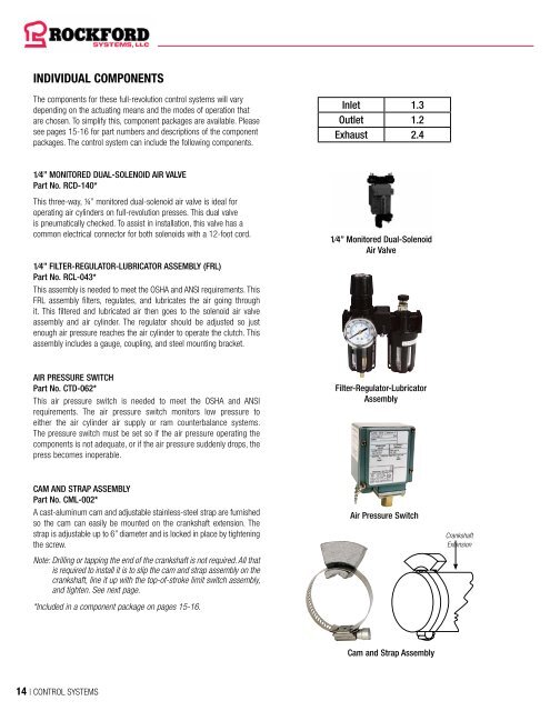
1⁄4” MONITORED DUAL-SOLENOID AIR VALVE<br />
Part No. RCD-140*<br />
This three-way, ¼” monitored dual-solenoid air valve is ideal <strong>for</strong><br />
operating air cylinders on full-revolution presses. This dual valve<br />
is pneumatically checked. To assist in installation, this valve has a<br />
common electrical connector <strong>for</strong> both solenoids with a 12-foot cord.<br />
1⁄4” FILTER-REGULATOR-LUBRICATOR ASSEMBLY (FRL)<br />
Part No. RCL-043*<br />
This assembly is needed to meet the OSHA and ANSI requirements. This<br />
FRL assembly filters, regulates, and lubricates the air going through<br />
it. This filtered and lubricated air then goes to the solenoid air valve<br />
assembly and air cylinder. The regulator should be adjusted so just<br />
enough air pressure reaches the air cylinder to operate the clutch. This<br />
assembly includes a gauge, coupling, and steel mounting bracket.<br />
1⁄4” Monitored Dual-Solenoid<br />
Air Valve<br />
AIR PRESSURE SWITCH<br />
Part No. CTD-062*<br />
This air pressure switch is needed to meet the OSHA and ANSI<br />
requirements. The air pressure switch monitors low pressure to<br />
either the air cylinder air supply or ram counterbalance systems.<br />
The pressure switch must be set so if the air pressure operating the<br />
components is not adequate, or if the air pressure suddenly drops, the<br />
press becomes inoperable.<br />
Filter-Regulator-Lubricator<br />
Assembly<br />
CAM AND STRAP ASSEMBLY<br />
Part No. CML-002*<br />
A cast-aluminum cam and adjustable stainless-steel strap are furnished<br />
so the cam can easily be mounted on the crankshaft extension. The<br />
strap is adjustable up to 6” diameter and is locked in place by tightening<br />
the screw.<br />
Note: Drilling or tapping the end of the crankshaft is not required. All that<br />
is required to install it is to slip the cam and strap assembly on the<br />
crankshaft, line it up with the top-of-stroke limit switch assembly,<br />
and tighten. See next page.<br />
*Included in a component package on pages 15-16.<br />
Air Pressure Switch<br />
Crankshaft<br />
Extension<br />
Cam and Strap Assembly<br />
14 | CONTROL SYSTEMS


