

Rockford Systems Control Systems for Presses Catalog
Catalog for control systems for mechanical power presses and press brakes, and hydraulic power presses and press brakes. These control systems are designed and built to comply with applicable OSHA regulations and ANSI standards. The catalog goes into detail about the features of the systems, and describes the different options available to update or replace existing control systems. This catalog also includes spring-loaded turnover bars, palm button assemblies, danger signs, and a section with helpful references. The catalog is divided into sections that offer control systems and components for: - Full-Revolution-Clutch Presses - Part-Revolution-Clutch Presses and Press Brakes - Hydraulic Presses and Press Brakes - Press Automation Control
Catalog for control systems for mechanical power presses and press brakes, and hydraulic power presses and press brakes. These control systems are designed and built to comply with applicable OSHA regulations and ANSI standards. The catalog goes into detail about the features of the systems, and describes the different options available to update or replace existing control systems. This catalog also includes spring-loaded turnover bars, palm button assemblies, danger signs, and a section with helpful references.
The catalog is divided into sections that offer control systems and components for:
- Full-Revolution-Clutch Presses
- Part-Revolution-Clutch Presses and Press Brakes
- Hydraulic Presses and Press Brakes
- Press Automation Control

You also want an ePaper? Increase the reach of your titles
YUMPU automatically turns print PDFs into web optimized ePapers that Google loves.
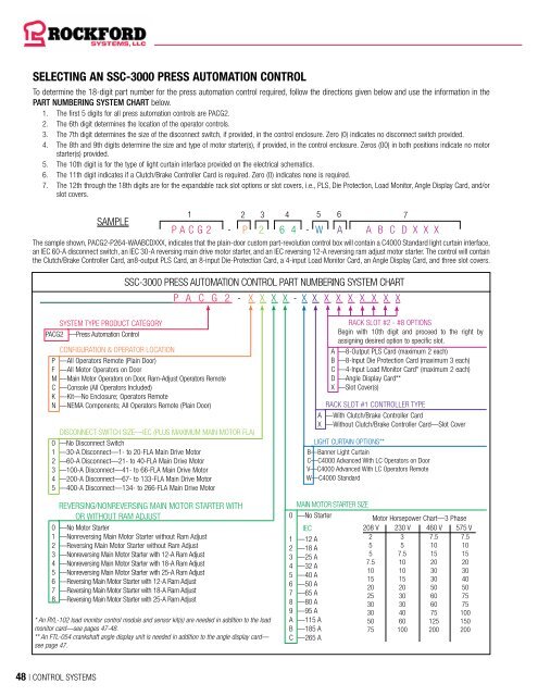
SELECTING AN SSC-3000 PRESS AUTOMATION CONTROL<br />
To determine the 18-digit part number <strong>for</strong> the press automation control required, follow the directions given below and use the in<strong>for</strong>mation in the<br />
PART NUMBERING SYSTEM CHART below.<br />
1. The first 5 digits <strong>for</strong> all press automation controls are PACG2.<br />
2. The 6th digit determines the location of the operator controls.<br />
3. The 7th digit determines the size of the disconnect switch, if provided, in the control enclosure. Zero (0) indicates no disconnect switch provided.<br />
4. The 8th and 9th digits determine the size and type of motor starter(s), if provided, in the control enclosure. Zeros (00) in both positions indicate no motor<br />
starter(s) provided.<br />
5. The 10th digit is <strong>for</strong> the type of light curtain interface provided on the electrical schematics.<br />
6. The 11th digit indicates if a Clutch/Brake <strong>Control</strong>ler Card is required. Zero (0) indicates none is required.<br />
7. The 12th through the 18th digits are <strong>for</strong> the expandable rack slot options or slot covers, i.e., PLS, Die Protection, Load Monitor, Angle Display Card, and/or<br />
slot covers.<br />
SAMPLE<br />
1 2 3 4 5 6 7<br />
P A C G 2 - P 2 6 4 - W A A B C D X X X<br />
The sample shown, PACG2-P264-WAABCDXXX, indicates that the plain-door custom part-revolution control box will contain a C4000 Standard light curtain interface,<br />
an IEC 60-A disconnect switch, an IEC 30-A reversing main drive motor starter, and an IEC reversing 12-A reversing ram adjust motor starter. The control will contain<br />
the Clutch/Brake <strong>Control</strong>ler Card, an8-output PLS Card, an 8-input Die-Protection Card, a 4-input Load Monitor Card, an Angle Display Card, and three slot covers.<br />
SSC-3000 PRESS AUTOMATION CONTROL PART NUMBERING SYSTEM CHART<br />
P A C G 2 - X X X X - X X X X X X X X X<br />
SYSTEM TYPE PRODUCT CATEGORY<br />
PACG2 —Press Automation <strong>Control</strong><br />
CONFIGURATION & OPERATOR LOCATION<br />
P —All Operators Remote (Plain Door)<br />
F —All Motor Operators on Door<br />
M —Main Motor Operators on Door, Ram-Adjust Operators Remote<br />
C —Console (All Operators Included)<br />
K —Kit—No Enclosure; Operators Remote<br />
N —NEMA Components; All Operators Remote (Plain Door)<br />
DISCONNECT SWITCH SIZE—IEC (PLUS MAXIMUM MAIN MOTOR FLA)<br />
0 —No Disconnect Switch<br />
1 —30-A Disconnect—1- to 20-FLA Main Drive Motor<br />
2 —60-A Disconnect—21- to 40-FLA Main Drive Motor<br />
3 —100-A Disconnect—41- to 66-FLA Main Drive Motor<br />
4 —200-A Disconnect—67- to 133-FLA Main Drive Motor<br />
5 —400-A Disconnect—134- to 266-FLA Main Drive Motor<br />
REVERSING/NONREVERSING MAIN MOTOR STARTER WITH<br />
OR WITHOUT RAM ADJUST<br />
0 —No Motor Starter<br />
1 —Nonreversing Main Motor Starter without Ram Adjust<br />
2 —Reversing Main Motor Starter without Ram Adjust<br />
3 —Nonreversing Main Motor Starter with 12-A Ram Adjust<br />
4 —Nonreversing Main Motor Starter with 18-A Ram Adjust<br />
5 —Nonreversing Main Motor Starter with 25-A Ram Adjust<br />
6 —Reversing Main Motor Starter with 12-A Ram Adjust<br />
7 —Reversing Main Motor Starter with 18-A Ram Adjust<br />
8 —Reversing Main Motor Starter with 25-A Ram Adjust<br />
* An RYL-102 load monitor control module and sensor kit(s) are needed in addition to the load<br />
monitor card—see pages 47-48.<br />
** An FTL-054 crankshaft angle display unit is needed in addition to the angle display card—<br />
see page 47.<br />
`<br />
RACK SLOT #2 - #8 OPTIONS<br />
Begin with 10th digit and proceed to the right by<br />
assigning desired option to specific slot.<br />
A —8-Output PLS Card (maximum 2 each)<br />
B —8-Input Die Protection Card (maximum 3 each)<br />
C —4-Input Load Monitor Card* (maximum 2 each)<br />
D —Angle Display Card**<br />
X —Slot Cover(s)<br />
RACK SLOT #1 CONTROLLER TYPE<br />
A —With Clutch/Brake <strong>Control</strong>ler Card<br />
X —Without Clutch/Brake <strong>Control</strong>ler Card—Slot Cover<br />
LIGHT CURTAIN OPTIONS**<br />
B—Banner Light Curtain<br />
C—C4000 Advanced With LC Operators on Door<br />
V—C4000 Advanced With LC Operators Remote<br />
W—C4000 Standard<br />
MAIN MOTOR STARTER SIZE<br />
0 —No Starter<br />
IEC<br />
1 —12 A<br />
2 —18 A<br />
3 —25 A<br />
4 —32 A<br />
5 —40 A<br />
6 —50 A<br />
7 —65 A<br />
8 —80 A<br />
9 —95 A<br />
A —115 A<br />
B —185 A<br />
C —265 A<br />
Motor Horsepower Chart—3 Phase<br />
208 V 230 V 460 V 575 V<br />
2 3 7.5 7.5<br />
5 5 10 10<br />
5 7.5 15 15<br />
7.5 10 20 20<br />
10 10 30 30<br />
15 15 30 40<br />
20 20 50 50<br />
25 30 60 75<br />
30 30 60 75<br />
30 40 75 100<br />
50 60 125 150<br />
75 100 200 200<br />
48 | CONTROL SYSTEMS


